
A Variation Reduction in the Tele-Abrasive System: A Study of Human Movement

1
School of Engineering, King Mongkut’s Institute of Technology Ladkrabang, Bangkok 10520, Thailand
2
Department of Industrial and Manufacturing Engineering, Faculty of Engineering, Prince of Songkla University, Hat-Yai 90110, Thailand
*
Author to whom correspondence should be addressed.
Appl. Sci. 2021, 11(16), 7298; https://0-doi-org.brum.beds.ac.uk/10.3390/app11167298
Submission received: 16 June 2021
/
Revised: 22 July 2021
/
Accepted: 27 July 2021
/
Published: 9 August 2021
(This article belongs to the Special Issue Intelligent Innovation in Engineering, Applied Sciences and Technology)
Abstract
:In a tele-abrasive task, it is principally human arm movements that cause variation in the position of the abrasive nozzle, thereby resulting in high operating costs and low productivity. It is difficult to design a system that can minimize the variation that accrues from operators behaving differently, which is difficult to predict. Although skilled operators can reduce this variation, becoming a skillful operator requires a lengthy training period. In this work, a two-stage variation streaming technique was used to extract variation sources in a tele-abrasive system. Furthermore, we propose an integrated human–computer approach to control variation in these systems—an approach that applies an innovative human arm movement pattern incorporated with a Kalman filter into a standard system. A virtual tele-abrasive system was used to validate our approach. Furthermore, compared with conventional systems, the proposed approach will help operators to perform abrasive tasks more comfortably and require a shorter training period.
1. Introduction
Due to the advancement in telecommunication technology, teleoperation has become a common part of many production systems. A tele-abrasive system is one of those systems combining a teleoperation system and an abrasive system to clean the surface of a large structure remotely [1,2]. This system has advantages over traditional abrasive systems in preventing operators from having accidents or health problems, enabling small- or large-scale tasks, and reaching inaccessible spots [3,4,5,6,7,8].
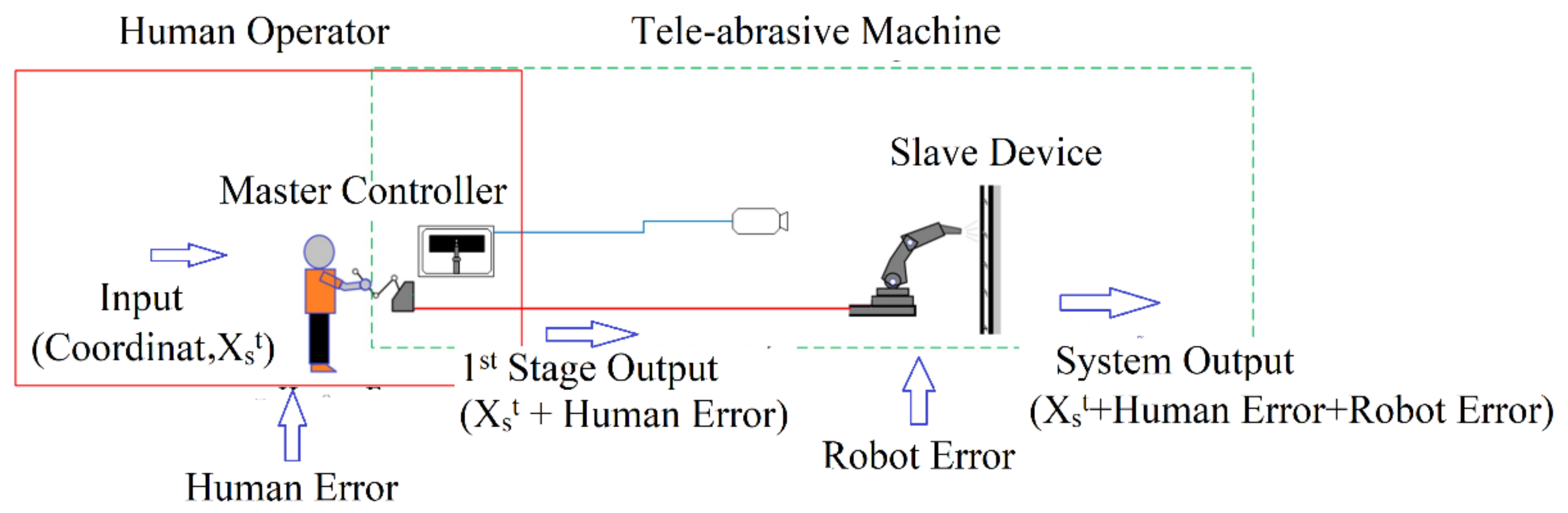
The tele-abrasive process is as follows: an operator moves the master controller to command the movement of the slave device, which has an abrasive nozzle at its end-effector to blast a target area, as shown in Figure 1.
Despite the many benefits of a tele-abrasive system, one of its significant drawbacks is the system variation that degrades the accuracy and precision of the abrasive nozzle position. There are several sources that cause system variation, such as visual perception [9], time delay [10], robot calibration [11], and human movement error [12]. Among these factors, human movement error in a tele-abrasive task has a unique characteristic and has not been solved. This problem occurs when a human operator controls the master controller with a lack of accuracy and precision. Consequently, the nozzle position is deviated from the target.
The deviation in the abrasive nozzle position caused by human movement error adds a great amount of variation to the total variation in the system output, which, over time, leads to an increase in operating costs and a decrease in productivity [13]. Conventionally, to reduce this variation, operators require intensive training or lengthy experience. This limitation poses more difficulty when worker replacement or a temporary increase in workers is needed.
In this study, the behavior of human movement error is observed and minimized. As the system output (the nozzle position) contains many sources of variation, it must be extracted to capture only the variation caused by human movement error. Therefore, a multi-stage variation stream was used to divide the system into two serial-connected stages, namely the human operator stage and the tele-abrasive machine stage. The variation sources of these stages are human movement error and manufacturing error, respectively. By dividing the system into stages, the variation from each source could easily be observed.
Then, an innovative human arm movement pattern is proposed, incorporated with a linear estimator to reduce the variation caused by human movement error that can easily be implemented and requires a short training period.
2. System Description
2.1. Tele-Abrasive Operation
A tele-abrasive system is a shared-control system where an operator and an automated machine operate the system together [14,15]. It is a teleoperation system that mainly consists of two main components, a human operator and a tele-abrasive machine, as shown in Figure 1. The operator interacts with the machine via the master controller to create a command for the slave device. Generally, the master controller is a passive manipulator—i.e., the operator controls the movement of the master controller. Then, its movement will be encoded as a movement command for the slave device.
The slave device is a manipulator that is sent into an environment that is changing, dangerous, and/or difficult for humans to reach. This device moves in accord with the command shared from the master controller. An abrasive nozzle is mounted at the end-effector to clean a surface. A camera is installed in the working area to capture the movement of the slave device for the operator.
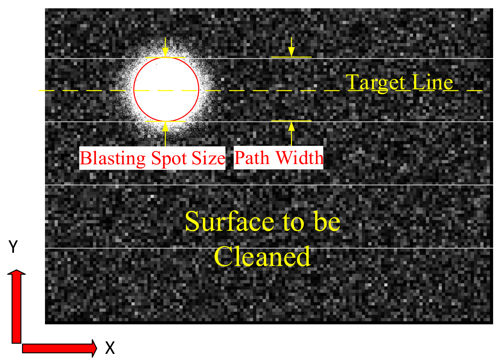
Typically, the surface area of the complex structure that is to be cleaned can be thought of as sub (flat, rectangular) are as connected. During the operation, the operator navigates the abrasive nozzle on a two-dimensional plane parallel to the surface. Thus, the tele-abrasive task motion in this study is considered in reference only to a two-dimensional movement on the surface (X-Y plane).
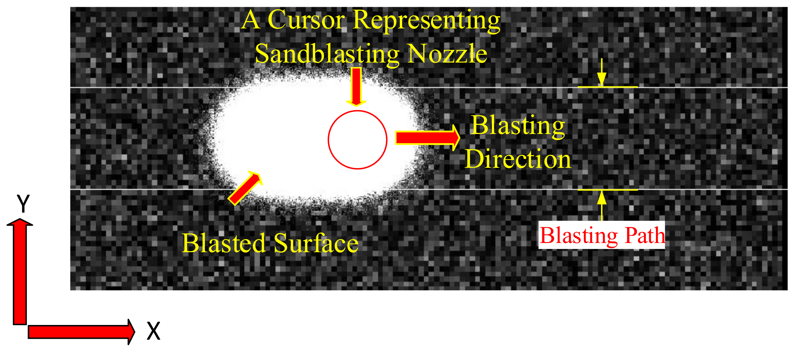
The purpose of this task is to clean the entire surface as quickly as possible. To minimize the time taken, the traveling distance to complete this task, and the costs associated with it, the width of the blasting path is set as equivalent to or slightly narrower than the blasted spot size [16], as shown in Figure 2. With this setup, an operator who navigates the nozzle inaccurately and imprecisely will produce poor surface quality. Therefore, in a conventional system, the path width is frequently set to be much narrower than the blasted spot size to cover variation caused by human arm movement error, which helps maintain surface quality. However, a narrower path results in a longer traveling distance, and then more time is required to complete the task. Consequently, the operator must be intensively trained to ensure that he or she is capable of performing the task competently and efficiently.
Among the sources of variation mentioned earlier, recent research has proposed many approaches in an effort to reduce variation by improving visual perception [9], stabilizing time delay [10], and maximizing robot accuracy [17,18,19]. However, in teleoperation tasks, although human arm movement is a main part of a shared-control system, human movement error has received very little research attention. In this general area, [14] proposed an adaptive network-based fuzzy inference system (ANFIS) model to control human arm movement velocity in a gas tungsten arc welding task. Furthermore, [20] considered the problem of the physical interface between a human and a computer, which requires an approach to help the human operator perform a hand movement task in a more comfortable and, hence, more reliable way.
In our tele-abrasive system, the variation in the tele-abrasive machine stage has been improved [19]. However, no research has considered the variation in the human operator stage (the position variation of the master controller caused by human error).
To consider only the variation caused by human error, the system output is not a good measure because it includes the variation caused by many sources. Therefore, a multi-stage variation stream was employed to categorize variation from each source and see how it propagates throughout the process.
2.2. Two-Stage System
The variation stream technique is used to identify the source of variation of serial production processes [21,22,23,24,25,26]. However, the conventional model was not designed for a continuous-time process, e.g., a tele-abrasive system.
To analyze our tele-abrasive system, we considered it as a two-stage system consisting of the human operator stage and the tele-abrasive machine stage, as shown in Figure 1.
To describe the variation in the stages of our system, a well-known state space model for variation propagation in multi-stage systems [27] was modified to extract the total variation and consider it according to stage variation in a continuous-time system manner, as given in Equations (1) and (2):
where state vector represents the key quality characteristic of the product at time t and stage ; is the transformation of product quality deviations from stage to stage at time t; represents the accuracy at time t and stage ; is a transformation matrix; is the unmodeled process error (precision); is a matrix mapping product quality state to quality measurement ; and is the measurement noise. Note that the superscripts denote stages, and the subscripts denote time intervals.
The expected value of is expressed in Equation (3):
Additionally, the expected value of is expressed in Equation (4):
Note that and are normally distributed with zero mean .
The variation in a stage can be expressed by the covariance of , shown in Equation (5):
The covariance of is:
The two-stage models presented earlier describe the variation stream for any time t. The average of the overall variation can be computed using Equations (7) and (8):
Similarly, the covariance of is:
Practically, can be calculated using Taguchi’s loss function [28]. At k =1, is equivalent to the square error as expressed in Equation (9):
where k is the loss coefficient, is the measured position at time t, and is the target value at time t.
Furthermore, can be obtained using Equation (10):
To employ Equations (1) and (2), we assume that the cleaning surface is rectangular. The target is a straight line along the horizontal axis (X-axis), as shown in Figure 2, and the system output is the position of the abrasive nozzle. Our variation refers to the deviation in the abrasive nozzle position on the Y-axis.
According to this model, an input of the system—the current position of the master controller, —is processed through stage 1, the human operator stage, and is moved to the next desired position by the human operator, . The output from stage 1, , includes the bias, , and precision, , of the operator and a measurement error, , which result in the master controller’s position deviating from the desired position. The total variation in the stage 1 output is represented by ], as expressed in Equation (5).
In stage 2, the machine receives a command to move to a human-controlled position. During this process, a variation occurs due to a machine calibration error, , a machine precision error, , and a measurement error, , which, in combination with the input, results in the abrasive nozzle position (output of the system, ) deviating from the position received from stage 1.
It is obvious that the variation propagates through the system. The output in the stage in which the variation occurs is affected. Likewise, the following stage and the system output are also affected. Therefore, a decrease in variation in the initial stage would result in a decrease in the total variation. Although variation caused by human operators has been referenced in the literature [20], variation arising from this cause has not been studied in this context. Additionally, as in stage 1, minimizing the variation caused by human arm movement error will reduce the covariance such that the variation in stage 2 is minimized. Furthermore, according to the previous experiment, the human operator produces a relatively large amount of the variation. Therefore, we focused on minimizing the variation caused by human movement error in stage 1.
The variation in position caused by human arm movement error can be considered to be related to accuracy (bias) and precision. A variation in the blasting line created by the human operator could relate to either or both of these. Furthermore, it should be noted that any given operator’s behavior is inconsistent. By using a conventional approach, it is, therefore, difficult to define a model to estimate the variation for a specific person. However, the approach we propose herein is designed to cope with exactly this problem.
3. The Proposed Approach
Our approach consists of two steps: (1) navigating the master controller with the proposed arm movement pattern to create variation with the desired pattern, and (2) using a linear estimator—which, in this paper, is the Kalman filter—to minimize such variation. The Kalman filter [29] is a recursive-form optimal estimator for continuous time problems that can be used to smooth out variation, as it provides discrete-time solutions in a one-step-ahead fashion, which is useful in various applications. Although for real-time and online applications, some stochastic estimation methods can produce a better state estimation, one-step-ahead estimators, such as the Kalman filter, are preferred, as they are computationally efficient and reliable [30]. Furthermore, the Kalman filter has high prediction accuracy, requires low computational complexity, does not store history data, and provides the quality of the estimation (estimation variance) [31].
3.1. Proposed Navigating Arm Movement Pattern
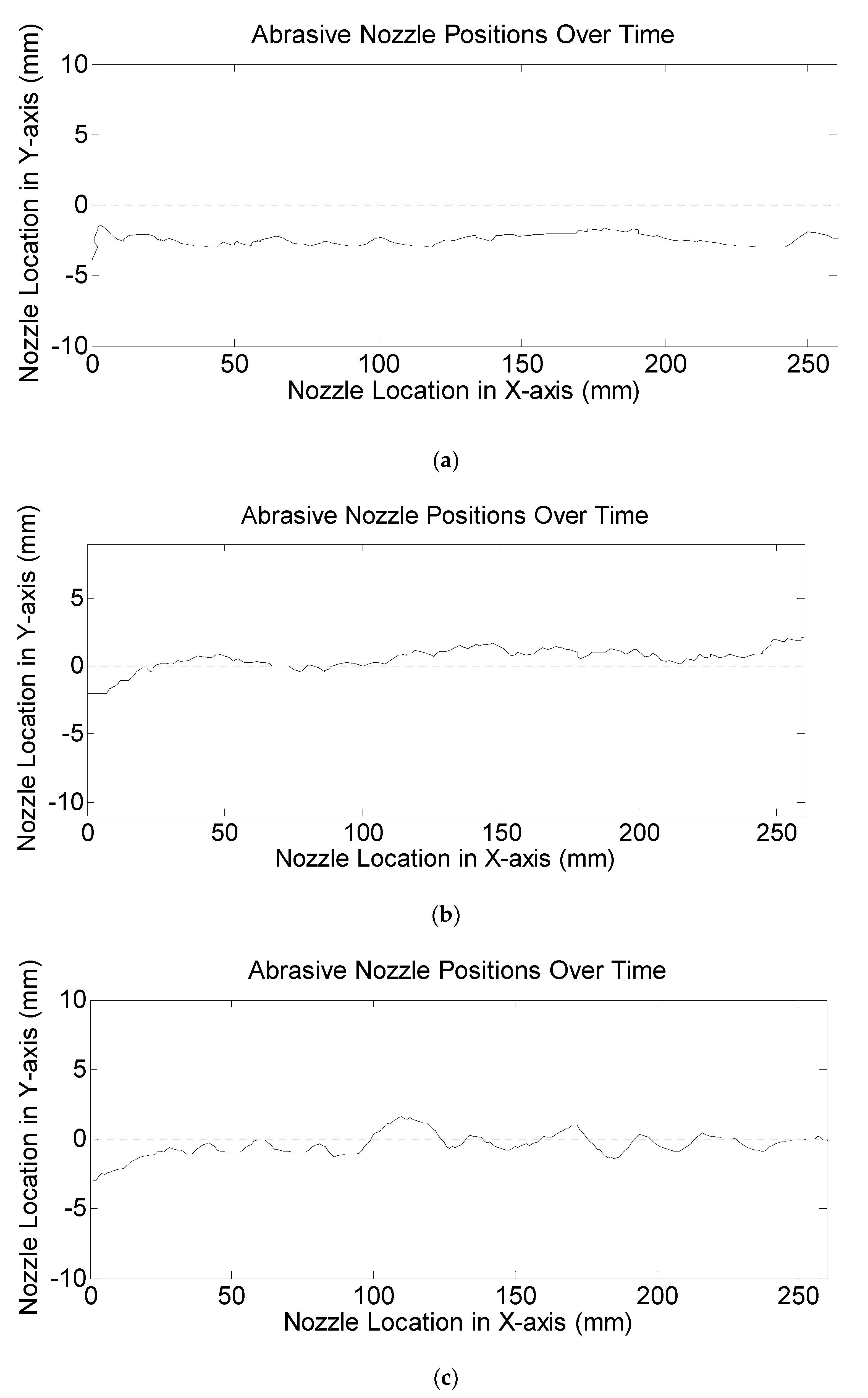
Consider the position (solid lines) obtained from three participants performing the task using the conventional approach as shown in Figure 3. The dotted lines in the center of the figures are the target positions. Because the operator is allowed to move freely within the path, it can be seen that the variations in Figure 3a–c are the different combinations of lack of accuracy and lack of precision, which are difficult to predict. Therefore, any given movement must be specified in advance.
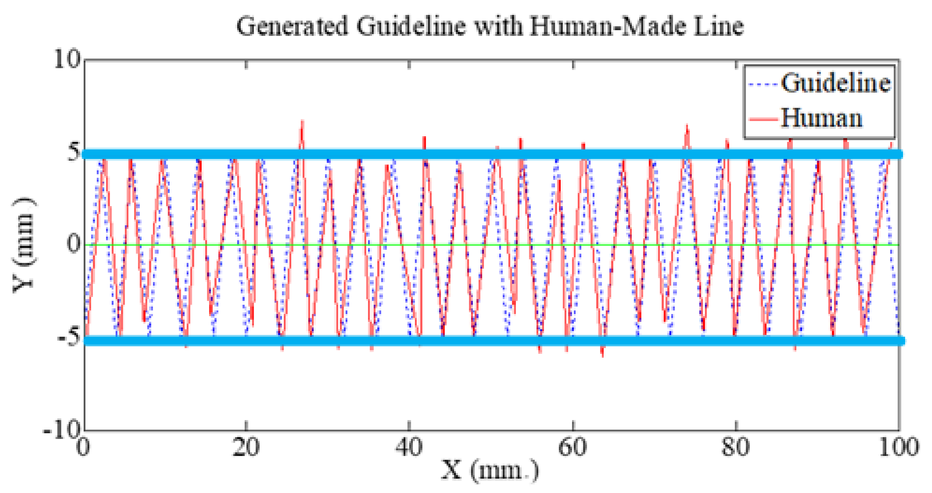
If we consider Figure 3c, the human-made line has a fluctuating pattern around the target that is similar to the noise in an electrical signal, which is usually smoothened out using a linear estimator. Thus, we came up with the concept that there must be a movement pattern that allows an operator to move more comfortably. Then, we added a tool into the process, such as a linear estimator (in case of a straight path), to improve the accuracy and precision. Therefore, we drew on this concept to address the variation in the position of the master controller by allowing the operator to move the master controller in a wave-like pattern around the target, as shown in Figure 4.
However, bias could occur in the positions such that the mean of the positions is far away from the target. In this case, the linearly estimated line will be far away from the target line too. To prevent such bias, the upper and lower boundaries of the path are set as targets for the crests and troughs of the waves.
The shape of the guideline is formed from a connection of multiple waves of the same size (amplitude and wavelength). As the task is performed by a human operator, human arm movement error causes differences in the amplitude and wavelength. The positions, therefore, form a bell-shape histogram, which imitates the random noise behavior in an electrical signal.
After this step, a jitter line is ready for the Kalman filter. Then, the Kalman filter is applied to the jitter line to filter it into a straight line.
3.2. Using Linear Estimation with the Kalman filter
The Kalman filter [29] is an approach used to minimize output variation by predicting the output based on previous values. Then, the output is updated based on the error between the measured output and the predicted output. The Kalman filter model is expressed in Equations (11) and (12):
where is the state vector containing the abrasive nozzle position at time t; is the state transition matrix that applies the effect of the system state parameter(s) at time t − 1 on the system state at time t; is the control input matrix that applies the effect of the control input parameter(s) in the vector on the state vector; is the vector containing the process disturbance or noise terms for the parameter(s) in the state vector; is the measurement vector; is a matrix that transforms the state vector into the measurement unit; and is the vector containing the measurement noise terms for observation(s) in the measurement vector.
In practical terms, the Kalman filter works by predicting the current state first. The prediction equation is given in Equation (13):
where is the predicted current state. Then, the confidence of the prediction, , is estimated by (14):
where is the covariance of the process noise, which is assumed to normally distribute with a zero mean. After the current state has been predicted by Equations (13) and (14), we can determine how good the prediction is by using the updating Equations (15)–(17) as follows:
where is the Kalman gain used in the updating process. The measurement noise is assumed to be normally distributed with a zero mean and covariance .
To apply the Kalman filter to the system, the quality measurement from stage 1, (see Equations (1) and (2)), is taken as an input to the Kalman filter. Then, the output from the Kalman filter, , is set to be the stage output.
4. Validation of The Proposed Approach
In this section, we describe the experiment set up to validate the proposed approach. Then, the results are reported and discussed.
4.1. Experiment Setup
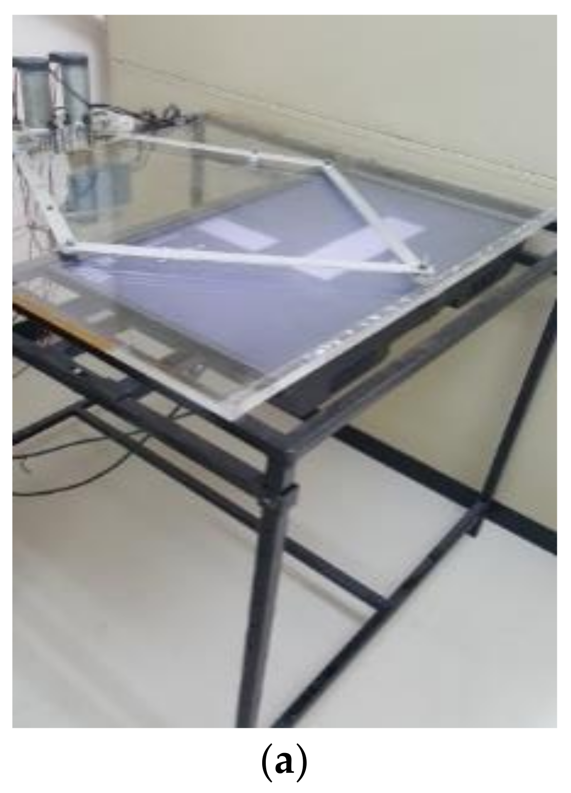
The experiment was conducted on a virtual tele-abrasive system, shown in Figure 5a [32]. The surface to be blasted was created virtually with a size of 275 × 25 mm and was placed horizontally along the X-axis (Figure 6); the path was 10 mm wide, and the target line was in the middle of the path (Figure 6).
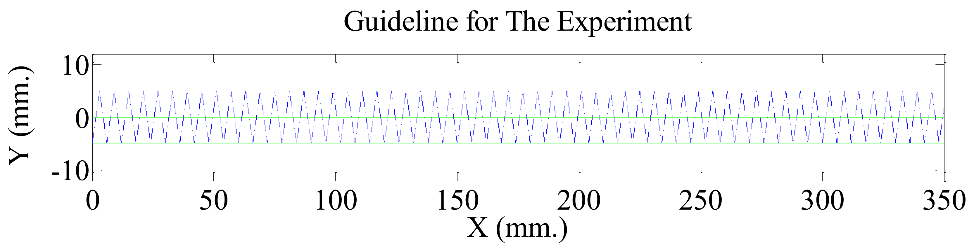
The guideline for training was designed to have an amplitude, H, of 10 mm; the wavelength, W, was 6 mm. The amplitude and wavelength were each set according to the numbers obtained from our preliminary experiment in order to find values that our participants were comfortable with in terms of the movements of their wrists and fingers during the operation. The guideline is shown in Figure 7.
The parameters of the state space model for stage 1 were set as follows:
- -
- and were assumed to be very small (very close to zero).
- -
- was set as 1.
The parameters for the Kalman filter were set as follows:
- -
- was set at 1, as the target line position was constant on the Y-axis (horizontally straight).
- -
- The term was zero, as there was no control input.
- -
- was set as equal to the MSE of the reference guideline, which was 8.324 for this experiment.
- -
- was set at 1.
In this experiment, a power analysis was used to identify the number of participants. In a small previous experiment, the standard deviation was 0.801. The confidence level was set at 95%. The power of testing was set to at least 90%. We expected that the proposed approach would help keep the average nozzle position closer to the target line by at least 1 mm. Minitab was used to calculate the number of participants, and it suggested that at least nine participants are required; therefore, we decided to have 10 participants for the experiment.
The participants were trained to use the conventional approach (a straight movement) to control the master controller to blast a surface covered by unwanted particles following a given path, but without a target line. They then performed this operation twice. In performing the task, the participants needed to visually judge the appropriate velocity such that the given path would be cleanly blasted. Then, they were trained to blast the surface using the proposed arm movement pattern with the guideline until they had become familiar with the pattern and velocity. Next, they performed the task using the proposed arm movement pattern without a guideline twice. We recorded the position of the master controller and the operating time for each operation.
4.2. Experimental Results
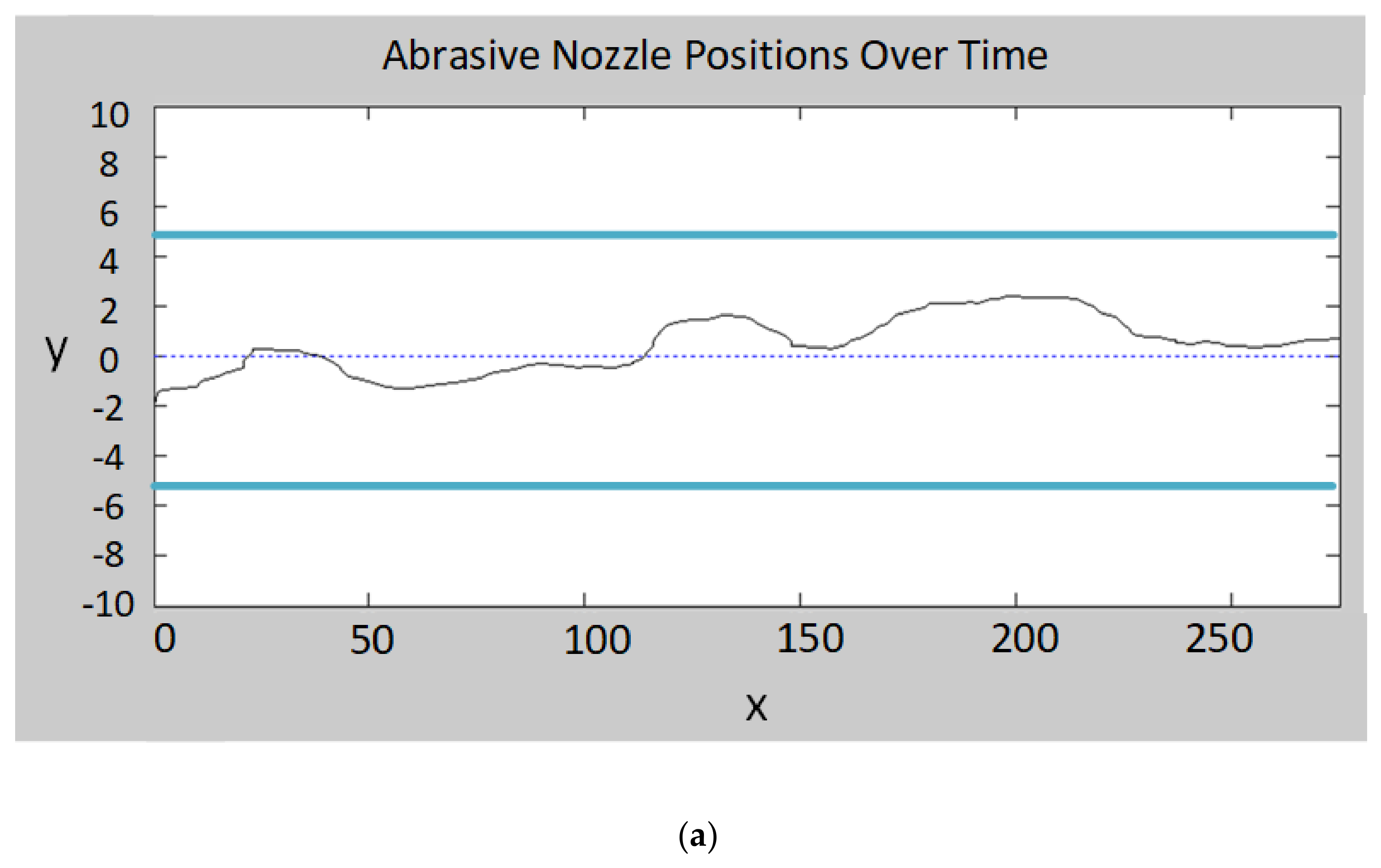
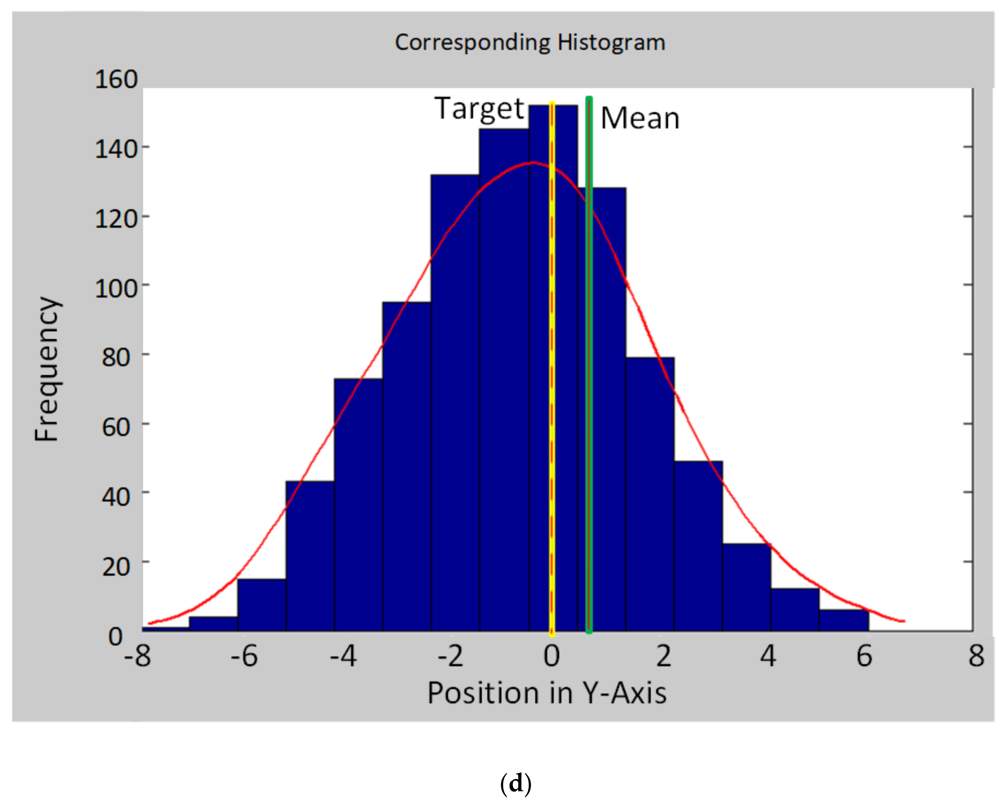
In this section, we discuss the results obtained from the experiment. First, the collected data were plotted to determine how the proposed arm movement pattern reformed the variation in the output. The plots of the master controller’s positions over time and the histograms of its position on the Y-axis in both the conventional approach and the proposed approach as undertaken by a participant are shown in Figure 8.
With the conventional approach, we can see both inaccuracy and imprecision throughout the blasting line (Figure 8a). The lack of accuracy was caused by the participants’ inability to guess the target accurately, whereas with the appropriate velocity, the participants struggled to maintain precision due to an inability to sufficiently control their arm movements, resulting in a high level of variance in the line. In Figure 8b, the histogram corresponding to Figure 8a clearly shows a low level of accuracy (the mean is far away from the target) and a low level of precision (multiple high-frequency bins), suggesting that the conventional approach is both inconsistent and unable to produce low variation in the output.
For the proposed approach, the plots of the master controller’s positions and the filtered output (Figure 8c) are represented by dash lines and solid lines, respectively. It can be seen that when the participants try to imitate the guideline under a constraint, i.e., appropriate velocity, human arm movement error appears as a variation in wavelength and amplitude. Focusing on the upper and lower boundaries, we can see that the participants failed to navigate the master controller to accurately and precisely touch and stay in contact with the guideline. Given the limits of human ability, this result was expected.
However, this characteristic of the wave line is suited to the Kalman filter because the error causes the data to form a bell-shaped histogram (imitating random noise in the electrical signal), as shown in Figure 8d. On this basis, the accuracy can be improved because when the operator moves the cursor to approximately come close to both boundaries of the path back and forth across the target line, there is a very high chance that the cursor will frequently cross the target line so that the frequency of the positions will be high at the value close to zero. Consequently, the filtered output, represented by the solid line, is straighter and closer to zero than the dash line produced by the conventional approach is, resulting in lower total variation.
Table 1 shows metrics describing the variation in the output from the human operator stage. The precision is represented by the mean square error (MSE), and the accuracy is represented by the absolute value of the difference between the mean and the target line. These values from the conventional approach and the proposed approach are compared next. The data obtained from participant 10 were excluded from the analysis since the data were considered as outliers.
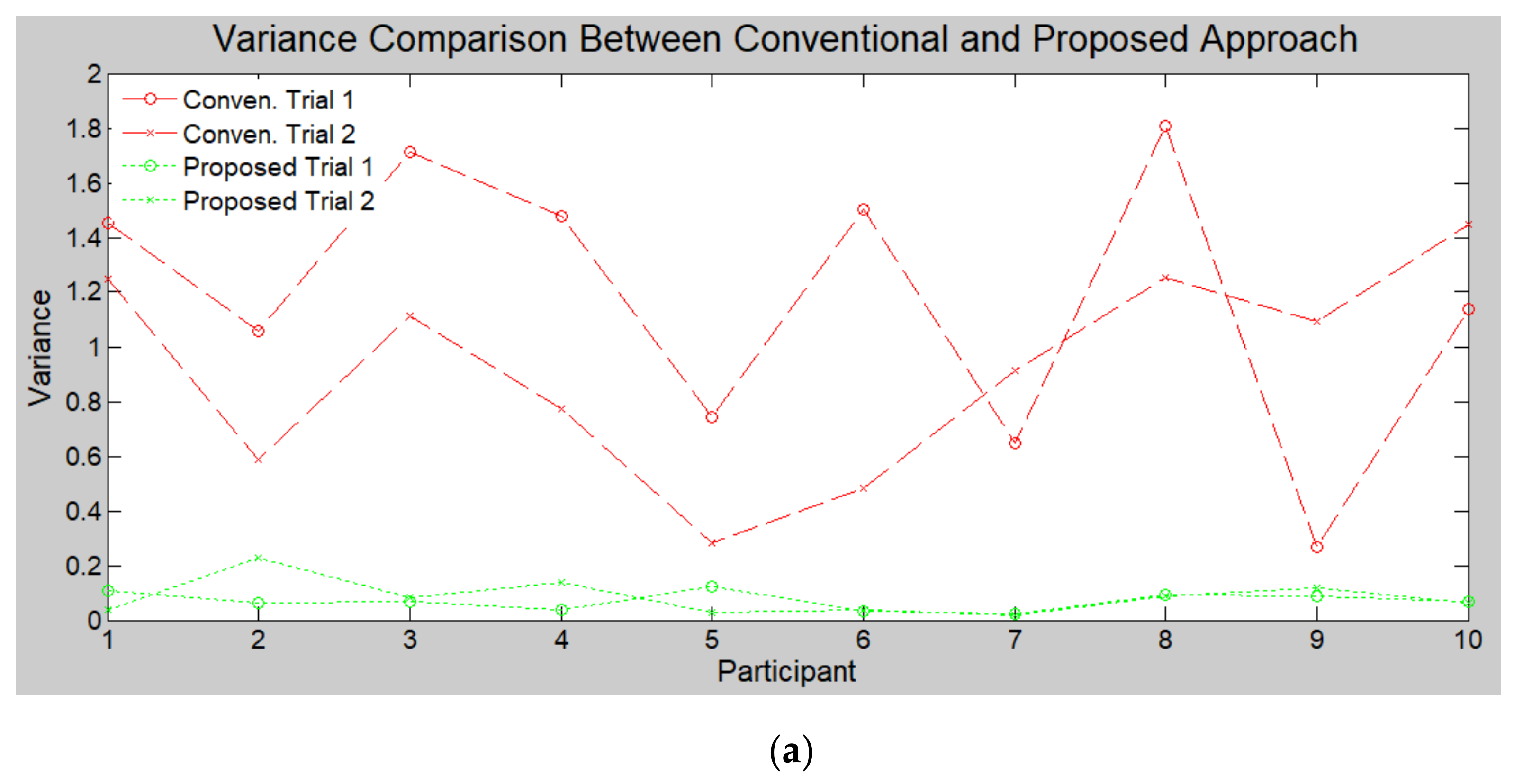
To assess the participants’ ability to imitate the guideline of the proposed arm movement pattern, we observed the MSE before filtering (). The average of the MSE from all the participants was 6.9329, whereas the guideline had an MSE of 8.3240. The difference between those MSEs is approximately 16.7%. This number indicates that despite being well trained, each participant created the pattern in accord with his or her preferred amplitude. Most of the participants preferred a lower amplitude than the guideline amplitude, as shown in a plot of individual variance in Figure 9a. However, a paired t-test suggested that the amplitudes from participants significantly differed in regard to the distance that each could cover with wrist-and-finger movement. Our finding supports the results reported in [33], according to which it is difficult for an operator to accurately move his or her hand to a desired position without the aid of visual information.
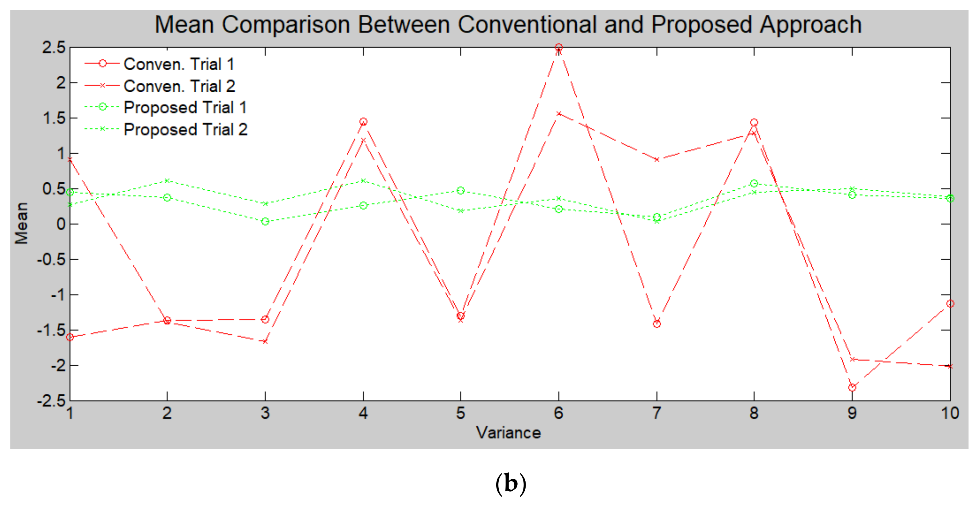
Meanwhile, the average accuracy before filtering was 0.7014, which is 53.09% better than that of the conventional approach at 1.4952. It suggests that the proposed approach helps participants to stay closer to the target line more on average than the conventional approach does, which ensures that the filtered output will be close to the target throughout the operation.
After filtering had taken place, the average precision of the proposed approach was 0.0783, whereas that of the conventional approach was 1.0231, indicating an improvement in precision of 92.34%. Likewise, the average accuracy of the proposed approach was 0.3381, whereas that of the conventional approach was 1.4952, indicating an improvement of 77.39%. The results from the paired t-test statistically prove that the proposed approach can minimize the variation in position caused by human arm movement error significantly. This improvement in total variation arises from the improvements in both precision and accuracy. Thus, the proposed arm movement pattern incorporating the Kalman filter significantly improves the precision and accuracy of the output.
This is because moving the master controller across the target instead of parallel to it helps to reduce the chance of missing the target line so that accuracy is maintained. Therefore, the error in accuracy is minimized (close to target). Then, the Kalman filter improves the precision (straightness). Moreover, Figure 9 shows that our approach improved consistency for individuals and reduced the difference among the participants.
5. Discussion
We have demonstrated the proposed approach and compared the results with those from the conventional approach. However, there are several topics worth mentioning. Recently, [20] highlighted the difficulty in a wrist flexion task. Although the authors suggested a joystick-like mechanism to increase the flexibility, we proposed a new movement pattern to free up the wrist while moving. While [12] presented a movement velocity analysis for a similar task, namely teleoperation for welding, we focused on a problem in the positioning of the end-effector. Hopefully, these two studies can be combined to improve the performance of the operator.
The use of the Kalman filter shown in this paper provided results as impressive as those from other Kalman applications [34,35]. Our results confirm that applying a linear estimator, specifically the Kalman filter, incorporated with the proposed arm movement pattern is viable for tele-abrasive and other similar applications. However, in this experiment, the traveling path was set at 10 mm, which is relatively small compared to other applications, such as aircraft navigation [36] and vehicle position estimation [37]. This is because the path width we selected in this experiment was set based on an empirical study to find the participant preference, where the result came out to be 10 mm.
However, the system can be adjusted to work with larger-scale experiments. The suggestions are as follows:
- If the real path is larger than the size used in the experiment, the movement between the master controller and the slave device can be scaled so that the operator can maintain the movement distance at which he or she best performs.
- If there are some errors remaining in the filtered output, they would be amplified during the scaling process. However, we can adjust the parameters in the Kalman filter, i.e., process covariance and measurement covariance, to minimize the error so that the setting is suitable with the scaled moving distance of the nozzle.
In addition, we have demonstrated how the proposed approach helps to reduce variation due to human arm movement error in the output of the human operator stage. The period needed to train each participant on the proposed arm movement pattern was relatively short (approximately 15 min per person).
After the experiment, we asked the participants the following two questions:
- Which type of movement did you perform with less stress and tension?
- Do you have a problem with the adjustment to the new movement pattern?
For the first question, all of the participants agreed that they worked with the proposed movement pattern more comfortably. Furthermore, seven of the participants did not have a problem adjusting to the new movement pattern. They thought that 15 min of training is sufficient to perform the task, and they believed that the longer they work, the better they can perform. However, three of the participants thought that they need more time for training. They suggested that the visual perception did not follow the habituation because their hands moved up and down vertically while the nozzle moved straight horizontally.
From the study, we can conclude that the operators feel more comfortable and relaxed with the proposed arm movement pattern as opposed to that in the standard system, and our pattern yielded a better system output as a result.
6. Conclusions
We used a variation streaming method to advance the field’s understanding of tele-abrasive systems. On this basis, we propose a new approach to tele-abrasive systems, consisting of two steps: navigating the arm movement pattern, and using a linear estimation with a Kalman filter. The jitter pattern we propose minimizes the error in accuracy, while the Kalman filter helps to improve precision. Consequently, the total variation is significantly reduced as compared to that generated by the conventional system. Our approach was validated using a virtual tele-abrasive system, which could be different from the real system.
Our approach can be an efficient alternative for tele-abrasive and similar tasks to assist operators, especially those prone to show high variation in the abrasive nozzle position. Additionally, all the participants stated that our approach is more comfortable for them to perform compared with the conventional approach, such that it leads to less stress and fatigue during the operation. Our approach can be applied to other similar applications, and we expect to see this happen over time.
In future work, we believe that this approach can be applied to path shapes other than a straight line as long as the path shapes can mathematically be approximated or the movement orientation is continually tracked. Other filtering techniques could be used to solve more complex path shapes, such as the Extended Kalman filter (EKF), the Madgwick filter, and the Mahony filter. Furthermore, the human arm movement pattern may be changed to suit the path shape such that the operator can comfortably perform the task.
Author Contributions
Conceptualization, R.J. and C.Y.; methodology, R.J.; software, R.J.; validation, R.J., C.Y. and S.C.; formal analysis, R.J.; investigation, R.J.; resources, C.Y.; data curation, R.J.; writing—original draft preparation, R.J.; writing—review and editing, C.Y. and S.C.; visualization, R.J.; supervision, C.Y.; project administration, C.Y.; funding acquisition, R.J. and C.Y. All authors have read and agreed to the published version of the manuscript.
Funding
This research was supported by funding from the School of Engineering, KMITL grant no. 2560-01-01027, and the National Science and Technology Development Agency grant no. FDA-CO-2563-12494-TH.
Institutional Review Board Statement
Not applicable.
Informed Consent Statement
Not applicable.
Data Availability Statement
Not applicable.
Acknowledgments
We would like to thank Kamtorn Sukpimai for technical support. We also thank all the participants who were involved in our study.
Conflicts of Interest
The authors declare no conflict of interest.
References
- Lorenc, S.; Handlon, B.; Bernold, L. Development of a robotic bridge maintenance system. Autom. Constr. 2000, 9, 251–258. [Google Scholar] [CrossRef]
- Chotiprayanakul, P.; Liu, D.K.; Dissanayake, G. Human–robot–environment interaction interface for robotic grit-blasting of complex steel bridges. Autom. Constr. 2012, 27, 11–23. [Google Scholar] [CrossRef]
- Sitti, M.; Hashimoto, H. Telenanorobotics using atomic force microscope. In Proceedings of the International Workshop on Intelligent Robots and Systems, Victoria, BC, Canada, 17 October 1998; pp. 1739–1746. [Google Scholar]
- Penin, L. Teleoperation with time delay: A survey and its issue in space robotics. In Proceedings of the 6th ESA Workshop Advanced Space Technology for Robotics Automation, Noordwijk, The Netherlands, December 2000; pp. 1–8. [Google Scholar]
- Hirche, S.; Stanczyk, B.; Buss, M. Transparent Exploration of Remote Environments by Internet Telepresence. In Proceedings of the International Workshop on High-Fidelity Telepresence and Teleaction jointly with the conference HUMANOIDS, Munich, Germany, 2003; Available online: https://mediatum.ub.tum.de/1168880?show_id=1188608 (accessed on 27 July 2021).
- Kron, A.; Schmidt, G.; Petzold, B.; Zah, M.F.; Hinterseer, P.; Steinbach, E. Disposal of explosive ordinances by use of a bimanual haptic telepresence system. In Proceedings of the IEEE International Conference on Robotics and Automation, New Orleans, LA, USA, 26 April–1 May 2004; pp. 1968–1973. [Google Scholar]
- Malysz, P.; Sirouspuor, S. Task performance evaluation of asymmetric semiautonomous teleoperation of mobile twin-arm robotic manipulators. IEEE Trans. Haptics 2013, 6, 484–495. [Google Scholar] [CrossRef]
- Polushin, I.G.; Takhmar, A.; Patel, R.V. Projection-based force-reflection algorithms with frequency separation for bilateral teleoperation. IEEE/ASME Trans. Mechatron. 2015, 20, 143–154. [Google Scholar] [CrossRef]
- Hoff, W.A.; Gatrell, L.B.; Spofford, J.R. Machine-vision-based teleoperation aid. Telemat. Inform. 1992, 8, 403–423. [Google Scholar] [CrossRef] [Green Version]
- Chang, Y.; Yang, C.; Lin, H. Adaptive control for bilateral teleoperation systems with time-varying delays. In Proceedings of the 2018 IEEE International Conference on Applied System Invention, Chiba, Japan, 13–17 April 2018; pp. 1111–1114. [Google Scholar]
- Filion, A.; Joubair, A.; Tahan, A.S.; Bonev, I.A. Robot calibration using a portable photogrammetry system. Robot. Comput.-Integr. Manuf. 2018, 49, 77–87. [Google Scholar] [CrossRef]
- Liu, Y.K.; Zhang, Y.M. Control of human arm movement in machine-human cooperative welding process. Control. Eng. Pract. 2014, 32, 161–171. [Google Scholar] [CrossRef]
- Jientrakul, R.; Yuangyai, C. Minimizing multi-stage system variation using Kalman filter for a tele-sandblasting system. In Proceedings of the IEEE International Conference on Management of Innovation and Technology (ICMIT), Bangkok, Thailand, 19–22 September 2016; pp. 133–138. [Google Scholar]
- Jientrakul, R.; Yuangyai, C.; Cheng, C.Y.; Chotiprayanakul, P.; Limnararat, S. Investigating multiple human performance measures in teleoperation task: A translation task in a tele-sandblasting maintenance system. Hum. Factors Ergon. Manuf. Serv. Ind. 2017, 18, 104–116. [Google Scholar] [CrossRef]
- Xue, B.; Yang, L.; Wu, J.; Liu, Z.; Xiong, Z. Model study on the traceability of the accuracy of an industrial manipulator to an external measurement system based on the Banach fixed-point theorem. Mech. Mach. Theory 2015, 92, 51–63. [Google Scholar] [CrossRef]
- Chen, S.J.; Huang, N.; Liu, Y.K.; Zhang, Y.M. Machine assisted manual torch operation: System design, response modeling, and speed control. J. Intell. Manuf. 2017, 28, 1249–1258. [Google Scholar] [CrossRef]
- Jientrakul, R.; Chotiprayanakul, P. Accuracy Improvement in Two-Dimensional Coordinate Mapping: A Parallel Robot for Engineering Laboratory. In Proceedings of the 2017 International Symposium on Multimedia and Communication Technology, Ayutthaya, Thailand, 23–25 August 2017. [Google Scholar]
- Popp, W.L.; Lambercy, O.; Müller, C.; Gassert, R. Effect of handle design on movement dynamics and muscle co-activation in a wrist flexion task. Int. J. Ind. Ergon. 2016, 56, 170–180. [Google Scholar] [CrossRef] [Green Version]
- Suri, R.; Otto, K. Variation modeling for a sheet stretch forming manufacturing system. Ann. CIRP 1999, 48, 397–400. [Google Scholar] [CrossRef]
- Huang, W.; Zhou, N.; Shi, J. Stream of variation modeling and diagnosis of multi-station machining processes. In Proceedings of the 2000 ASME International Mechanical Engineering Congress & Exposition, Orlando, FL, USA, 5–10 November 2000; Volume 11, pp. 81–88. [Google Scholar]
- Djurdjanovic, D.; Ni, J. Linear state space modeling of dimensional machining errors. Trans. NAMRI/SME 2001, 29, 541–548. [Google Scholar]
- Zhou, S.; Huang, Q.; Shi, J. State space modeling of dimensional variation propagation in multistage machining process using differential motion vectors. IEEE Trans. Robot. Autom. 2003, 19, 296–309. [Google Scholar] [CrossRef]
- Yuangyai, C.; Nembhard, H.B.; Hayes, G.; Antolino, N.; Adair, J.H. Yield improvement for lost mould rapid infiltration forming process by a multistage fractional factorial split plot design. Int. J. Nanomanuf. 2009, 3, 351–367. [Google Scholar] [CrossRef] [PubMed]
- Yuangyai, C.; Lin, K.J. Understanding multistage experiments. Int. J. Exp. Des. Process. Optim. 2013, 3, 384–409. [Google Scholar] [CrossRef]
- Shi, J. Stream of Variation Modeling and Analysis for Multistage Manufacturing Process; CRC Press: Boca Raton, FL, USA, 2007; pp. 117–141. [Google Scholar]
- Taguchi, G.; Chowdhury, S.; Wu, Y. Part III: Quality Loss Function Taguchi’s Quality Engineering Handbook; John Wiley and Sons: Hoboken, NJ, USA, 2005; pp. 171–198. [Google Scholar]
- Kalman, R.E. A new approach to linear filtering and prediction problems, Transaction of the ASME. J. Basic Eng. 1960, 82, 35–45. [Google Scholar] [CrossRef] [Green Version]
- Jientrakul, R.; Limnararat, S.; Yuangyai, C.; Srisuebsai, W.; Chotiprayanakul, P. Investigating of human-robot collaboration in a mixed-reality tele-sandblasting maintenance system. In Proceedings of the 16th Asia Pacific Industrial Engineering and Management Systems Conference, Ho Chi Minh City, Vietnam, 8–11 December 2015. [Google Scholar]
- Huang, J.; Kosaka, S.; Imamura, Y.; Yabuta, T. Measurement of distance error in reaching movement of the human hand without using vision. In Proceedings of the 29th Annual International Conference of the IEEE Engineering in Medicine and Biology Society, Lyon, France, 22–26 August 2007; pp. 4866–4869. [Google Scholar]
- Chang, G. Kalman filter with both adaptivity and robustness. J. Process. Control 2014, 24, 81–87. [Google Scholar] [CrossRef]
- Toivanen, M. An advanced Kalman filter for gaze tracking signal. Biomed. Signal Process. Control 2016, 25, 150–158. [Google Scholar] [CrossRef]
- Crandall, J.W.; Goodrich, M.A. Characterizing efficiency of human robot interaction: A case study of shared-control teleoperation. IEEE/RSJ Int. Conf. Intell. Robot. Syst. 2002, 2, 1290–1295. [Google Scholar]
- Dragan, A.D.; Srinivasa, S.S. A policy-blending formalism for shared control. Int. J. Robot. Res. 2013, 32, 790–805. [Google Scholar] [CrossRef]
- Forbes, J.R.; de Ruiter, A.H.J.; Zlotnik, D.E. Continuous-Time Norm-Constrainted Kalman Filtering. Autom. 2014, 50, 2546–2554. [Google Scholar] [CrossRef]
- Wei, G.; Ling, Y.; Guo, B.; Bin, X.; Vasillakos, A.V. Prediction-based data aggregation in wireless sensor networks: Combining grey model and Kalman Filter. Comput. Commun. 2011, 34, 793–802. [Google Scholar] [CrossRef]
- Spingarn, K. Passive Position Location Estimation Using the Extended Kalman Filter. IEEE Trans. Aerosp. Electron. Syst. 1987, 23, 558–567. [Google Scholar] [CrossRef]
- Luo, C.; McClean, S.I.; Parr, G.; Teacy, L.; De Nardi, R. UAV Position Estimation and Collision Avoidance Using the Extended Kalman Filter. IEEE Trans. Veh. Technol. 2013, 62, 2749–2762. [Google Scholar] [CrossRef]
Figure 1.
Tele-abrasive system.

Figure 2.
A surface subjected to a tele-abrasive operation where the blasted spot is controlled along the target line to blast the path.
Figure 2.
A surface subjected to a tele-abrasive operation where the blasted spot is controlled along the target line to blast the path.

Figure 3.
The nozzle position obtained from three participants performing the task using the conventional approach: (a) a participant who lacks accuracy (b) a participant who lacks precision (c) a participant who performs best but the positions still show the lack of both accuracy and precision.
Figure 3.
The nozzle position obtained from three participants performing the task using the conventional approach: (a) a participant who lacks accuracy (b) a participant who lacks precision (c) a participant who performs best but the positions still show the lack of both accuracy and precision.

Figure 4.
An example of a guideline (dash) with a human-made line (solid).

Figure 5.
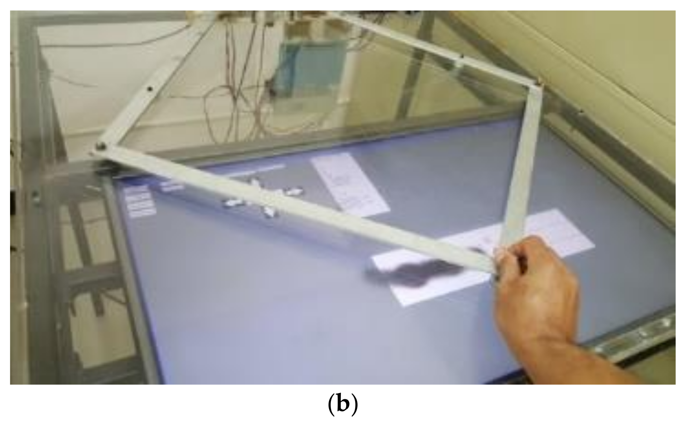
(a) A virtual tele-abrasive workstation. (b) An example of the blasting operation.


Figure 6.
Surface to be blasted in the experiment.

Figure 7.
Guideline for the experiment.

Figure 8.
An example of the master controller’s positions from the experiment and the histograms of its positions on the Y-axis: (a) plot of the conventional approach and (b) the corresponding histogram; (c) plot of the proposed approach and (d) the corresponding histogram of the positions before filtering.


Figure 9.
Plot comparisons of the (a) variance and (b) mean between the conventional approach and the proposed approach.
Figure 9.
Plot comparisons of the (a) variance and (b) mean between the conventional approach and the proposed approach.


Table 1.
A comparison between the precision and accuracy obtained from the conventional approach and the proposed approach.
Table 1.
A comparison between the precision and accuracy obtained from the conventional approach and the proposed approach.
| Conventional | Proposed | |||||
|---|---|---|---|---|---|---|
| Before Filtering | After Filtering | |||||
| Precision (MSE) | Accuracy (Mean) | Precision (MSE) | Accuracy (Mean) | Precision (MSE) | Accuracy (Mean) | |
| Average | 1.0500 | 1.5000 | 6.9329 | 0.7015 | 0.0770 | 0.3408 |
| Standard Deviation | 0.4550 | 0.3983 | 1.1774 | 0.3377 | 0.0514 | 0.1780 |
Publisher’s Note: MDPI stays neutral with regard to jurisdictional claims in published maps and institutional affiliations. |
© 2021 by the authors. Licensee MDPI, Basel, Switzerland. This article is an open access article distributed under the terms and conditions of the Creative Commons Attribution (CC BY) license (https://creativecommons.org/licenses/by/4.0/).
Share and Cite
MDPI and ACS Style
Jientrakul, R.; Yuangyai, C.; Chaiprapat, S. A Variation Reduction in the Tele-Abrasive System: A Study of Human Movement. Appl. Sci. 2021, 11, 7298. https://0-doi-org.brum.beds.ac.uk/10.3390/app11167298
AMA Style
Jientrakul R, Yuangyai C, Chaiprapat S. A Variation Reduction in the Tele-Abrasive System: A Study of Human Movement. Applied Sciences. 2021; 11(16):7298. https://0-doi-org.brum.beds.ac.uk/10.3390/app11167298
Chicago/Turabian StyleJientrakul, Ranon, Chumpol Yuangyai, and Supapan Chaiprapat. 2021. "A Variation Reduction in the Tele-Abrasive System: A Study of Human Movement" Applied Sciences 11, no. 16: 7298. https://0-doi-org.brum.beds.ac.uk/10.3390/app11167298
Note that from the first issue of 2016, this journal uses article numbers instead of page numbers. See further details here.