Article

Fundamental Numerical Analysis of a Porous Micro-Combustor Filled with Alumina Spheres: Pore-Scale vs. Volume-Averaged Models

1
Key Laboratory of Efficient Utilization of Low and Medium Grade Energy, Ministry of Education, Tianjin University, Tianjin 300350, China
2
Department of Energy and Power Engineering, School of Mechanical Engineering, Tianjin University, Tianjin 300350, China
3
School of Transportation and Vehicle Engineering, Shandong University of Technology, Zibo 255000, China
*
Author to whom correspondence should be addressed.
Submission received: 6 July 2021 / Revised: 5 August 2021 / Accepted: 10 August 2021 / Published: 16 August 2021

Abstract

:
Inserting porous media into the micro-scale combustor space could enhance heat recirculation from the flame zone, and could thus extend the flammability limits and improve flame stability. In the context of porous micro-combustors, the pore size is comparable to the combustor characteristic length. It is insufficient to treat the porous medium as a continuum with the volume-averaged model (VAM). Therefore, a pore-scale model (PSM) is developed to consider the detailed structure of the porous media to better understand the coupling among the gas mixture, the porous media and the combustor wall. The results are systematically compared to investigate the difference in combustion characteristics and flame stability limits. A quantified study is undertaken to examine heat recirculation, including preheating and heat loss, in the porous micro-combustor using the VAM and PSM, which are beneficial for understanding the modeled differences in temperature distribution. The numerical results indicate that PSM predicts a scattered flame zone in the pore areas and gives a larger flame stability range, a lower flame temperature and peak solid matrix temperature, a higher peak wall temperature and a larger Rp-hl than a VAM counterpart. A parametric study is subsequently carried out to examine the effects of solid matrix thermal conductivity (ks) on the PSM and VAM, and then the results are analyzed briefly. It is found that for the specific configurations of porous micro-combustor considered in the present study, the PSM porous micro-combustor is more suitable for simplifying to a VAM with a larger Φ and a smaller ks, and the methods can be applied to other configurations of porous micro-combustors.

1. Introduction

With the rapid development of micro-electro-mechanical systems (MEMS), the demand for miniaturized power devices becomes increasing urgent. The present main power sources for miniaturized electronics and micro-propulsion systems are conventional electrochemical batteries [1]. However, there are many disadvantages for these batteries, such as the long recharging periods, the low energy densities and the short service life [2]. Owing to the higher energy densities of hydrogen and hydrocarbon fuels compared with batteries, micro-scale combustors were used as the heat source to provide power for miniaturized power systems, such as the micro-thermophotovoltaic (TPV) systems [3] or the thermoelectric (TE) systems [4]. Since 1991, when the concept of “micro machinery” was first proposed by Epstein and Senturia [5], various micro-power systems have been tested [6,7,8] and significant progress has been achieved in both basic and applied studies on micro-power systems and micro-combustion.
Differing from macro-scale combustors, the combustor size is reduced to a millimeter and the increased surface-to-volume ratio intensifies the heat losses from the wall [9], making it difficult to sustain stabilized flames. Therefore, it is crucial to develop effective flame stabilization technologies for small-scale combustors. Many useful strategies have been suggested, such as the backward-facing step in cylindrical tubes [10,11] to prolong the residence time and strengthen the mixing of the fuel mixture; catalytic combustion [12,13] to suppress radical depletion; Swiss-roll combustor configuration [14]; and porous media combustion [15,16,17] to enhance heat recirculation.
Two approaches are commonly employed in simulations to model the reaction and heat transfer in a porous combustor: the volume-averaged model (VAM) and pore-scale model (PSM). In theoretical analysis and numerical studies, the VAM is commonly applied to study porous media combustion. The VAM assumes a local thermal equilibrium between the gas and solid phases (the one-temperature model) [18,19] or allows for a thermal nonequilibrium (the two-temperature model) [15,20], which typically treats porous media as an equivalent fluid with similar thermophysical properties, and pore-scale geometric characteristics lumped into the equivalent fluid. The simplicity of the calculation model and lower computational expense of the VAM provide a foundation for understanding the global fluid flow and heat recirculation characteristics in porous media. Therefore, the VAM approach had made a substantial contribution to the design and operation of porous micro-combustors.
Research results based on the VAM are greatly challenged by the lack of understanding of porous combustion due to the model’s limitations. Although the VAM combined with the thermal nonequilibrium model can satisfactorily predict the global temperature distribution, detailed porous media structures are not used in the computational domain because detailed information at the pore-scale is filtered out [21]. A more precise numerical method, the PSM, is necessary to understand the combustion characteristics at the pore-scale and to investigate the flow [22], reaction and heat transfer [23] inside the porous media. Abdelsalam et al. [23] performed a theoretical analysis of variable thermophysical features and the heat and mass transport phenomena of viscous fluid flow through a porous channel. The characteristic of the porous medium can be studied by Darcy-Forchheimer expression. Oliveira et al. [24] pointed out that the PSM model is necessary when the pore size and channel height are comparable.
Sahraoui and Kaviany [25] studied filtration combustion in a porous medium made of discrete or connected square cylinders and found that the VAM predicted a higher burning velocity and lower superadiabatic temperature than the PSM. The limitation of the VAM was reflected in the powerless expression of detailed information in small spaces, which are comparable to the combustor characteristic length. In other words, the VAM could not predict the overall pore-level simulation results, including temperature and species distribution. Additionally, solid radiative heat transfer was ignored because of the computational cost. Hackert et al. [26] extended the above study by including solid-solid radiative heat recirculation. They developed a 2D pore-scale model of two simple porous structures to study the effect of multidimensionality on flames, and determined the limitations of one-dimensional models.
In a PSM study by Jouybari et al. [27], pore-scale filtration combustion within discrete square cylinders was numerically simulated to investigate the effects of turbulence and multidimensionality on flame characteristics. They revealed that turbulence in the preheating zone could increase the diffusion before the flame front, but it was not enough to affect key flame characteristics such as temperature distribution and maximum flame velocity of the porous media.
Bedoya et al. [28] experimentally and numerically studied the effects of pressure and equivalence ratio on flame stability within the pores of porous inert media, employing a 1D VAM and 3D PSM on real geometries of sponge-like structures. They found that the PSM could be used to predict the average temperature distribution along the space coordinates of the combustors. The VAM demonstrated a steeper slope, indicating lower flame thickness than in the experiments. Rabinovich et al. [29] simplified the complex construction of a discrete-modeled porous medium to a regular periodic structure composed of three elements: solid particles, gas flow zone and gas stagnation zone. A numerical study on the fundamental combustion process of premixed methane–air combustion was carried out based on the simplified approach. It showed that the velocity of flame propagation increased considerably near the gas stagnation zone when elementary cells were larger than 3 mm.
As mentioned above, notable advances have been achieved in filtration combustion at the pore scale. However, heat transfer through the combustor wall is ignored in recent PSM numerical simulations of porous combustors [21,24,25,26,27,28,29]. In micro-/meso-scale combustors, heat recirculation through the combustor wall is crucial to self-sustaining and stabilizing flames, confirmed by a series of free flame cases and VAM numerical simulations [30,31,32,33,34,35,36]. In Norton and Vlachos’ paper [30], computational fluid dynamics simulations of methane and propane combustion were performed to study the effects of key parameters on combustion characteristics and flame stability. They found that at the micro-/meso-scale, the walls were responsible for the majority of the external heat losses and upstream heat transfer. Therefore, the wall thermal conductivity was the primary parameter that determined the stabilization and self-sustainability of the flames. Kang and Veeraragavan [31] investigated the effects of a novel thermally orthotropic material on flame stability based on a full understanding of the significance of the combustor wall. Veeraragavan and Cadou [32] affirmed that the heat recirculation via thermal conduction in the combustor wall was vital for determining the flame speed. Li et al. [33] considered the solid matrix and combustor wall to be the pathways for heat recirculation in the porous micro-combustor. The thermal conduction in the combustor wall was significant for preheating the unburned gas mixture.
This study develops a PSM of a structurally arranged porous media made of discrete alumina spheres to produce a quantitatively accurate porous micro-combustor. To understand reaction and heat transfer in porous micro-combustors more accurately, this study considers the PSM model and the heat transfer between the gas mixture and combustor wall. The remainder of this paper discusses the following:
(1)
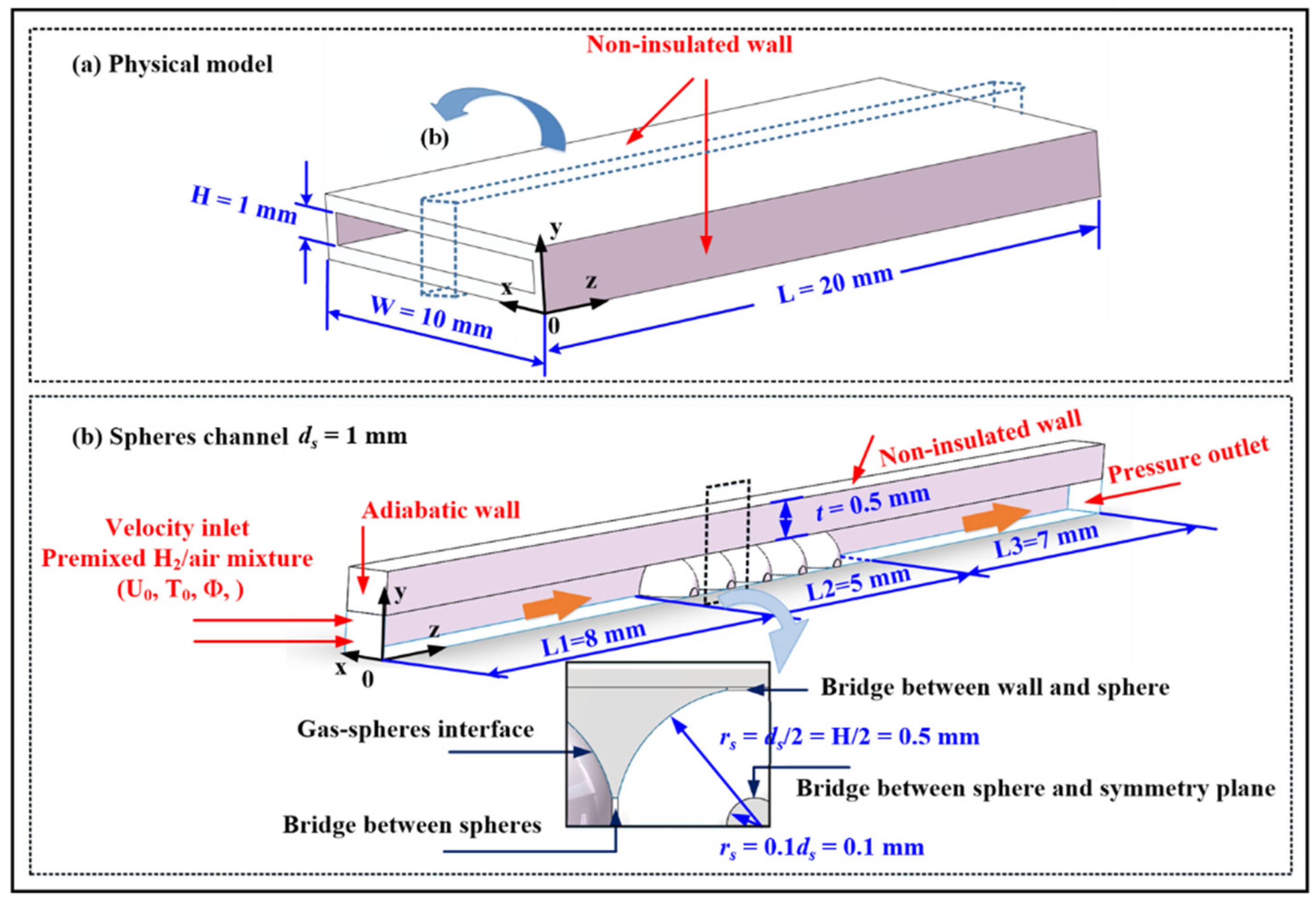
The combustion of H2/air in a regularly packed bed of alumina spheres is numerically simulated using a 3D PSM. The energy conservation equation of the solid matrix and combustor wall are combined to examine the temperature distribution in a porous micro-combustor.
(2)
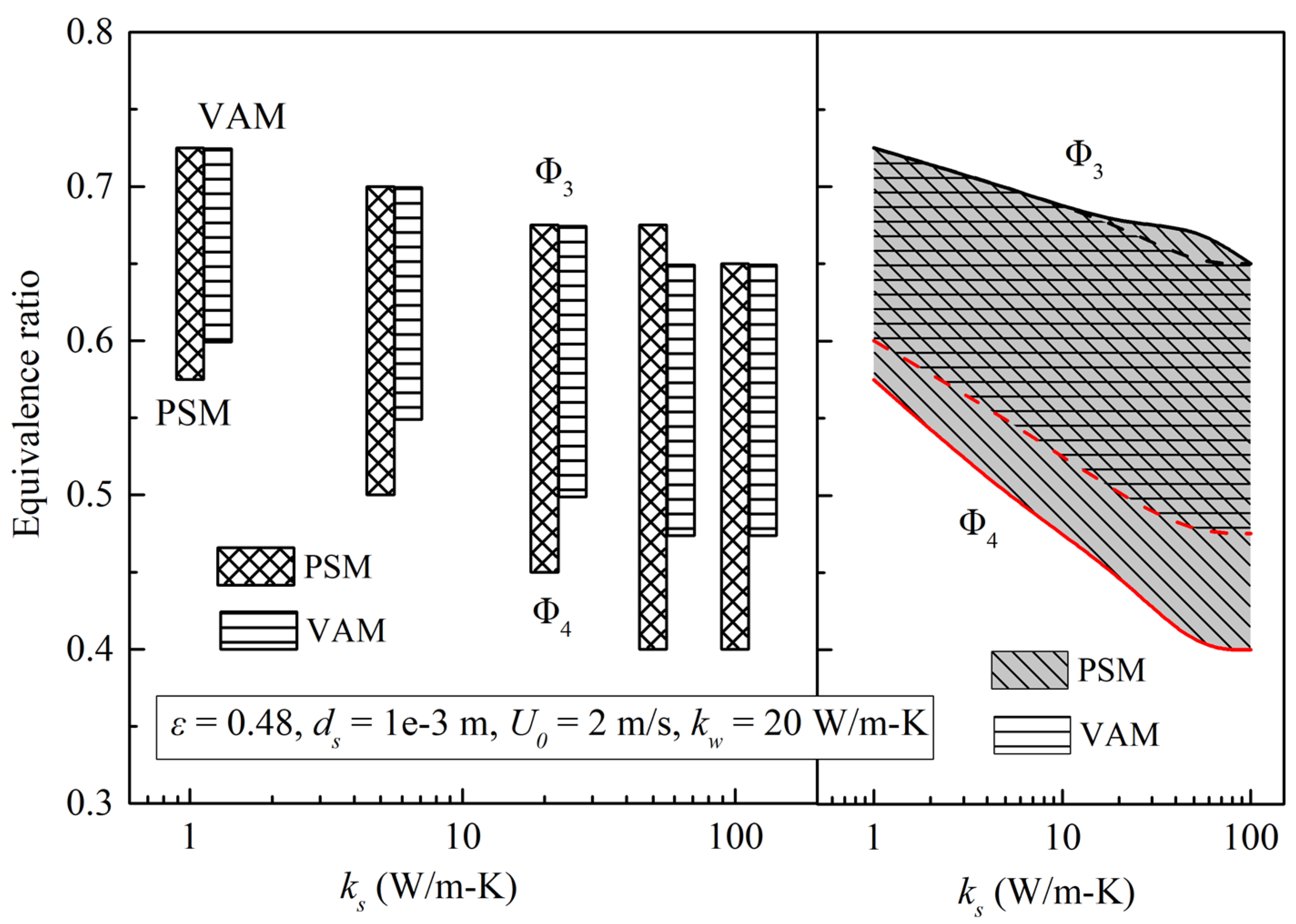
The simulation results based on the PSM are systematically compared with those obtained by the VAM to analyze the combustion characteristics and flame stability limits.
(3)
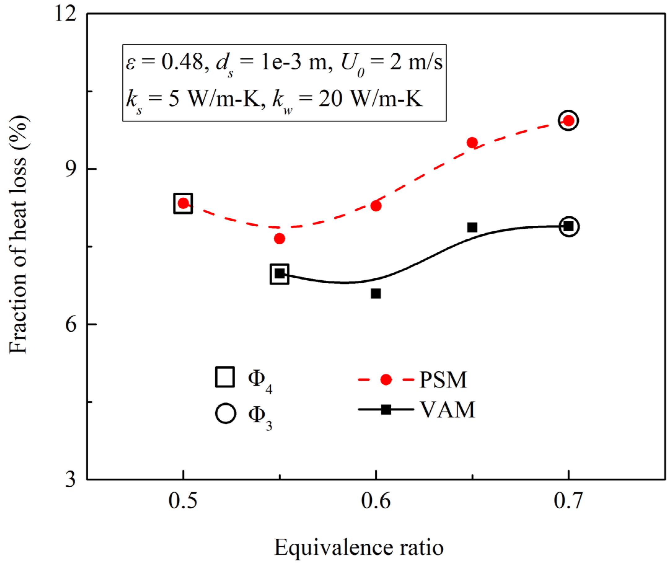
The heat recirculation is examined, including preheating and heat loss, in the porous micro-combustor using the VAM and PSM.
(4)
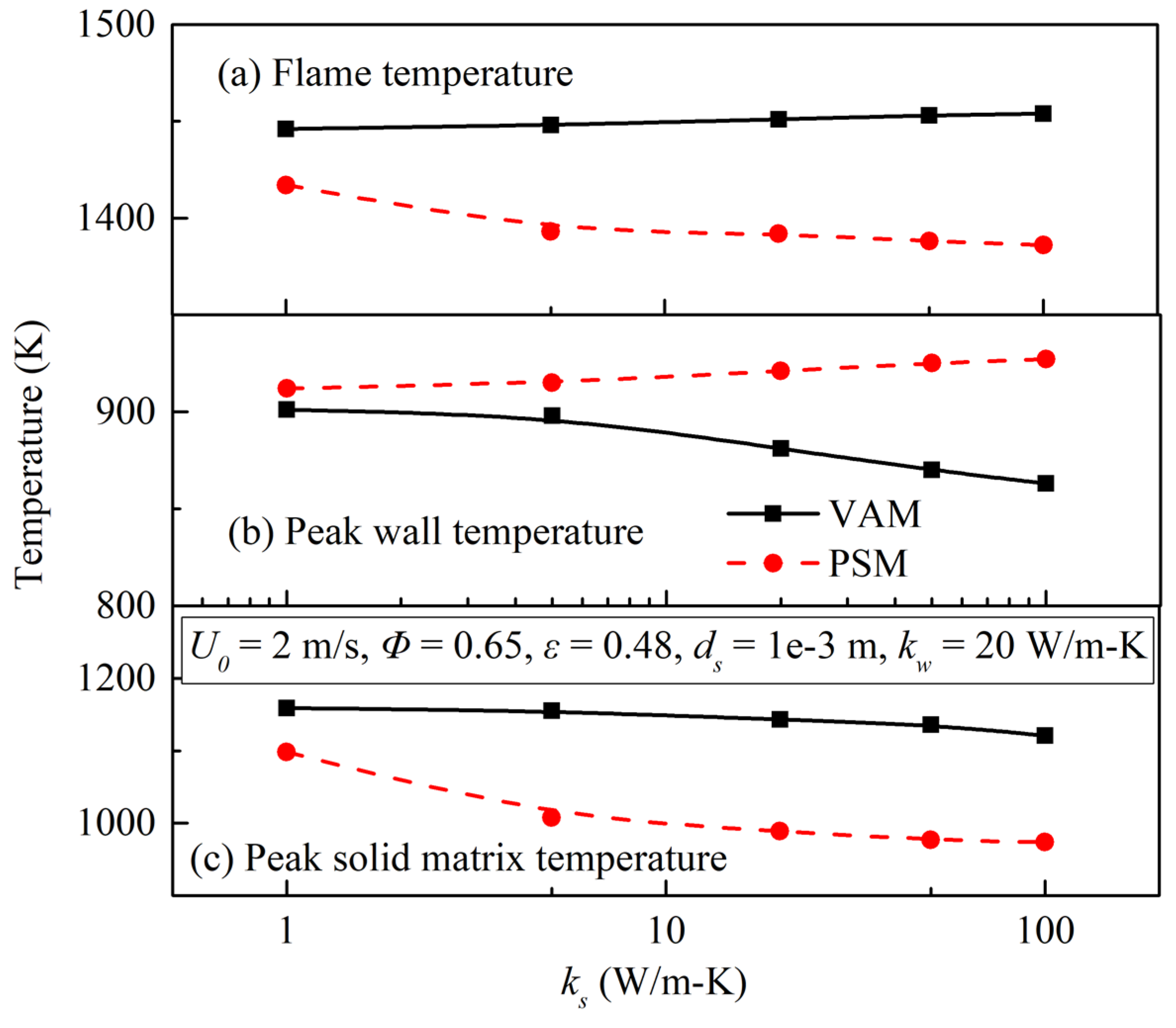
A parametric study is carried out to examine the effects of solid matrix thermal conductivity (ks) on the PSM and VAM.

2. Modeling

2.1. Pore-Scale Model

Figure 1a illustrates the design features of a porous micro-combustor. The length, width and height of the combustor are 20, 10 and 1 mm, respectively. The wall thickness t is 0.5 mm. The planar micro-combustor is partially filled with alumina spheres with ds = 1 mm, producing a porosity ε of 0.48. The alumina spheres have a thermal conductivity of 5 W/m-K [37]. The combustor is made of SS 316 L and has a wall thermal conductivity of 20 W/m-K. The large aspect ratio (=10) leads to the same temperature distribution in the wall surface and channels along the x direction.
In view of the symmetry, only half of a channel is considered to save computational time, as shown in Figure 1b. In numerical simulations, sphere-sphere and wall-sphere contact points often present difficulties in mesh quality. In order to eliminate the contact points, cylinders with a radius of 0.1 ds [38] are artificially created between contacted spheres or a sphere and wall surface that are in contact, as shown in Figure 1b.
To eliminate the non-essential factors in the mathematical formulation, the following assumptions are made: (1) ideal gases and incompressible flows [36]; (2) steady-state combustion [33]; (3) no Dufour and Soret effects; (4) no gas radiation; (5) no work done by pressure and viscous forces; (6) inert porous medium [33].
The conservation equations are written as follows:
Continuity:
  ( ε ρ g u g ) x +   ( ε ρ g v g ) y +   ( ε ρ g w g ) z = 0
x-Momentum:
ρ g u g u g x + ρ g v g u g y + ρ g w g u g z = p x + μ   ( 2 u g x 2 + 2 u g y 2 + 2 u g z 2 )
y-Momentum:
ρ g u g v g x + ρ g v g v g y + ρ g w g v g z = p y + μ   ( 2 v g x 2 + 2 v g y 2 + 2 v g z 2 )
z-Momentum:
ρ g u g w g x + ρ g v g w g y + ρ g w g w g z = p z + μ   ( 2 w g x 2 + 2 w g y 2 + 2 w g z 2 )
Energy equation in the gas phase:
ρ g c g u g T g x + ρ g c g v g T g y + ρ g c g w g T g z = x   ( k g T g x ) + y   ( k g T g y ) + z   ( k g T g z ) ω i W i Q + q r
Energy equation in the solid phase:
x   ( k s T s x ) + y   ( k s T s y ) + z   ( k s T s z ) = 0
Mass conservation for the ith species:
ρ g u g Y i x + ρ g v g Y i y + ρ g w g Y i z = x   [ D i ( ρ g Y i ) x ] + y   [ D i ( ρ g Y i ) y ] + z   [ D i ( ρ g Y i ) z ] + ω i W i
Energy equation in the combustor wall:
x   ( k w T w x ) + y   ( k w T w y ) + z   ( k w T w z ) = 0
where the wall thermal conductivity kw is 20 W/m-K [39].
The boundary conditions applied in the PSM are shown in Figure 1b. Premixed H2/air is fed into the inlet of the micro-scale combustor, and has a given velocity, equivalence ratio and mixture temperature (T0 = 300 K). The far-field pressure outlet is set to 1 atm at the exit. A simplified reaction mechanism comprising 6 species and 7 elementary reactions is taken from Ref. [38] for the combustion chemistry. The solid radiative heat transfer between the inner surfaces is analyzed using the discrete ordinate model [40]. Heat loss from the non-insulated walls is composed of two parts, convection and radiation, and is governed by:
q w = h   ( T w 0 T a ) + ε r σ   ( T w 0 4 T a 4 )
where the convective heat loss coefficient h is 20 W/m2-K [39], the ambient temperature Ta is 300 K [33,36,39], the emissivity of non-insulated wall is 0.8 [36] and the Stephan–Boltzmann constant σ is 5.67 × 10⁻⁸ W/m2-K4 [2,33,36,39,41,42].
The governing equations are discretized and solved numerically using the CFD software FLUENT® [43]. The non-conformal grids with tetrahedral elements are generated by Pointwise®. A reasonable grid density is determined using a mesh independence study, as seen in Figure 2a. The results demonstrate that a grid with 357,355 nodes is sufficiently fine to capture both the centerline and wall temperature profiles, and a higher number of nodes (434,459) does not yield significant improvement. As such, non-uniform meshes with 357,355 nodes are used in the following tests, and the local mesh gradation is shown in Figure 2b. In order to accurately capture the temperature and velocity gradients, the highest grid density is applied near the gas–solid and gas–wall interfaces with four layers of T-Rex grids for a layer thickness of △s= 1 μm (Region I in Figure 2b).
A moderate density is used in the fluid (Region II) and solid (Region Ⅲ) regions, while the lowest density is in the wall (Region IV).

2.2. Volume-Averaged Model

To ensure consistency and comparability, the physical model and boundary conditions of the VAM are obtained based on the PSM. The model simplification method and governing equations can be found in our earlier paper [33]. Specifically, the empirical correlation found previously [44] is applied to solve the volumetric heat transfer coefficient between sphere and gas phases.

3. Results and Discussion

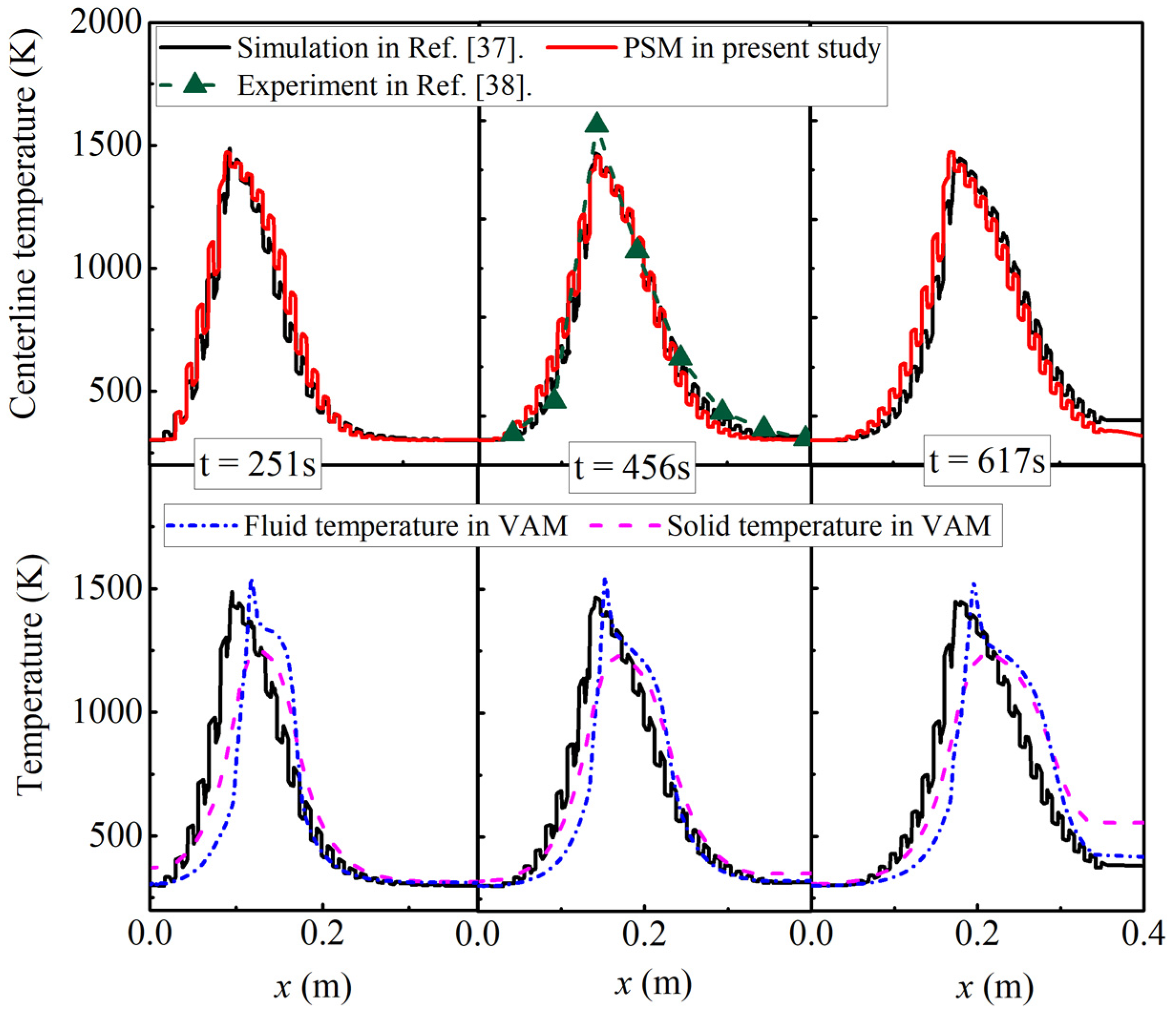
3.1. Model Validation

It is difficult to realize the structured arrangement of porous media due to the size constraint in the micro-/meso-scale combustors. This results in difficulties for the experimental study of filtration combustion around alumina spheres. Therefore, the lack of experimental data leads to difficulties in the direct validation of the PSM numerical model.
Shi et al. [40] designed a 2D packed bed of discrete cylinders with a staggered arrangement based on the high realizability of the structured arrangement of porous media at the macro scale. They also confirmed the accuracy of the model from to the consistent trend between the numerical solution and experiment results of Zhdanok et al. [45]. To ensure comparability, discrete and continuum models are developed in the first step of this study with parameter values identical to those used by Shi et al. [40].
Figure 3 compares the centerline temperature of the experimental data and numerical results obtained by the PSM of Shi et al. [40], the VAM and the PSM in present study. The results indicate that, according to temperature trends and value of the fluid mixture and porous media, pore-scale numerical results are well aligned with the numerical results of Shi et al. [40] and experimental results of Zhdanok et al. [45], as shown in the above plot of Figure 3. Some deviation of the VAM can be found in the below plot of Figure 3, because the simplification of VAM incurred some error in the centerline temperature profile. The validity of the proposed numerical PSM model is also indirectly demonstrated.

3.2. Fundamental Combustion Characteristics for the VAM and PSM

Upon validating the PSM numerical model, a comparative study was carried out to examine the temperature distribution differences between the VAM and PSM. In order to ensure comparability, the same key parameters (U0, Φ, ks, kw, ε, and ds) were used for both calculation models. Figure 4 compares the temperature contours and OH concentration of the planar porous micro-combustor.
It can be found in Figure 4a that the VAM predicts a parabolic flame front and the highest temperature region at the centerline, while the flame profile obtained by the PSM is irregular in three dimensions as the flame front is distributed along the surface of alumina spheres. It should be noted that the PSM predicts a more scattered high temperature distribution region and a lower peak flame temperature.
To further understand the temperature distribution and flame characteristics of the PSM, three planes (x = 0, 0.25, and 0.5 mm) were selected for this test component, as shown in Figure 4b,c. The flame fronts are distributed along the surface of the alumina spheres for the PSM, forming tiny flames in the pore areas. A higher OH concentration and flame temperature are found with a more concentrated flame distribution at x = 0, as shown in Figure 4c.
The flame zone becomes scattered when x increases from 0 to 0.25 mm. At the same time, the OH concentration and flame temperature greatly reduce. Furthermore, a minimum flame temperature and minimum temperature difference between the fluid and porous media is predicted at x = 0.5 mm.
Figure 5 shows the flame temperatures, peak wall temperature and peak solid matrix temperature obtained by the VAM and PSM variation with Φ in the porous micro-combustor partially filled with alumina spheres with ds of 1 mm, ε of 0.48 and ks of 5 W/m-K. It is shown that under the same inlet flow conditions (U0 and Φ), the porous combustor using PSM gives a much lower flame temperature and peak solid matrix temperature and a higher peak wall temperature than the VAM counterpart. There are basically three causes for this. First, in the VAM combustor, the heat recirculation through solid-wall heat exchange is ignored, resulting in the heat flux error. The solid-to-wall heat exchange (qs-w) between the solid matrix and wall in the PSM combustor leads to a higher wall temperature and a lower porous temperature. Second, different from the flame central region of the VAM combustor located in along the centerline, the PSM combustor forecasts a primary flame zone at the pore position, which is closer to the wall, and consequently poses a positive effect on the wall temperature. Third, the volumetric heat transfer between the gas mixture and porous media exhibits differences because of the different temperature distribution and surface heat transfer areas. In other words, based on the verification of the PSM, there are errors in the volumetric heat transfer coefficient between the gas mixture and alumina spheres calculated by the empirical correlation in the VAM.
Another obvious pattern shown in Figure 5 is that the difference between two calculation models in terms of flame temperatures, peak wall temperature and peak solid matrix temperature decreases with the increase in Φ.
In Figure 5, an equivalence ratio range is obtained in which the flame can be stabilized within the porous medium. According to a previous study [39], critical flame stability limits, Φ3 and Φ4 marked by the circle and square in Figure 5, are key features of planar micro-combustor designs. It can be found that in the simulated result of porous combustor using the PSM, the flame stability range is found to be obviously better. For the concrete manifestation of the Φ3 almost independent of the model construction method and a lower equivalence ratio to blow off from the upper boundary of the porous media.

3.3. Heat Recirculation for VAM and PSM

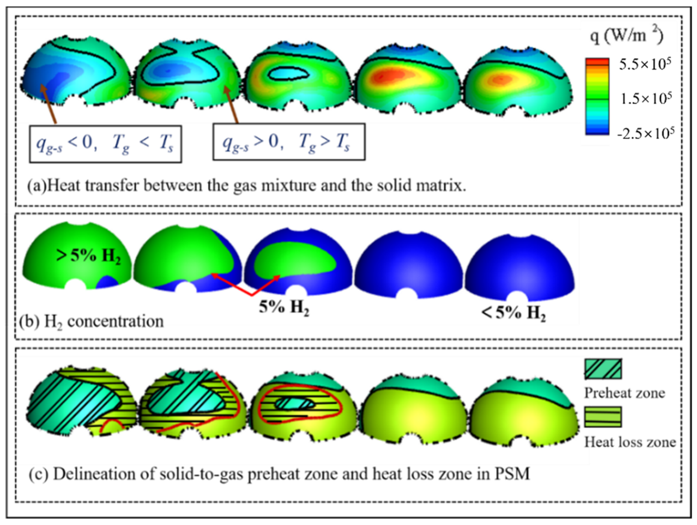
3.3.1. Definition of Solid-To-Gas Preheating Zone and Heat Loss Zone

In micro-combustion, the conjugate heat transfer calculation among gas mixture, wall and solid matrix is helpful to gain more in-depth insights into the heat transfer processes of the VAM and PSM combustors.
Referring to the definition of a preheating zone and heat loss zone in the VAM combustor, Tg is lower than Ts in the qg−s < 0 region, meaning that heat is transferred from the solid matrix to the gas mixture. In the qg−s > 0 region, heat released from chemical reactions leads to higher Tg and lower Ts. Hence, the contour with qg−s = 0 is the boundary to separate the preheating and heat loss zones. The contour with H2 = 5% is identified as the end of the heat loss zone. Therefore, the region determined by qg−s < 0 and H2 > 5% is called the “preheat zone,” and the “heat loss zone” and is identified as the region determined by qg−s > 0 and H2 > 5%, as shown in Figure 6.
In our previous study [39], the contour with qg−s = 0 and H2 = 5% was continuous for the VAM combustor. The reaction zone in the PSM combustor displays a number of scattered regions because of multiple small flames, and the contours thus divided multiple scattered areas.

3.3.2. Heat Recirculation through Solid-To-Wall Heat Exchange

As already mentioned, solid-to-wall heat exchange (qs−w) between the solid matrix and wall has an important influence on the temperature distribution of the PSM combustor, as shown in Figure 5. Solid-to-wall heat exchange efficiency is represented by the following expression:
η s w = | A p q s w d A | / Q c
where Ap refers to the contact heat transfer area between the solid matrix and wall. Qc refers to the total heat release calculated from the lower heating value of H2 (∼120 MJ/kg).
Figure 7 shows that in the PSM combustor, Φ has an obvious effect on ηs−w, that is, the larger Φ is, the smaller is ηs−w. Therefore, the influence of solid-to-wall heat exchange on the PSM calculation model decreases with the increase in Φ, which is consistent with the results shown in Figure 5, that is, the temperature difference between the PSM and VAM decreases with the increase in Φ.

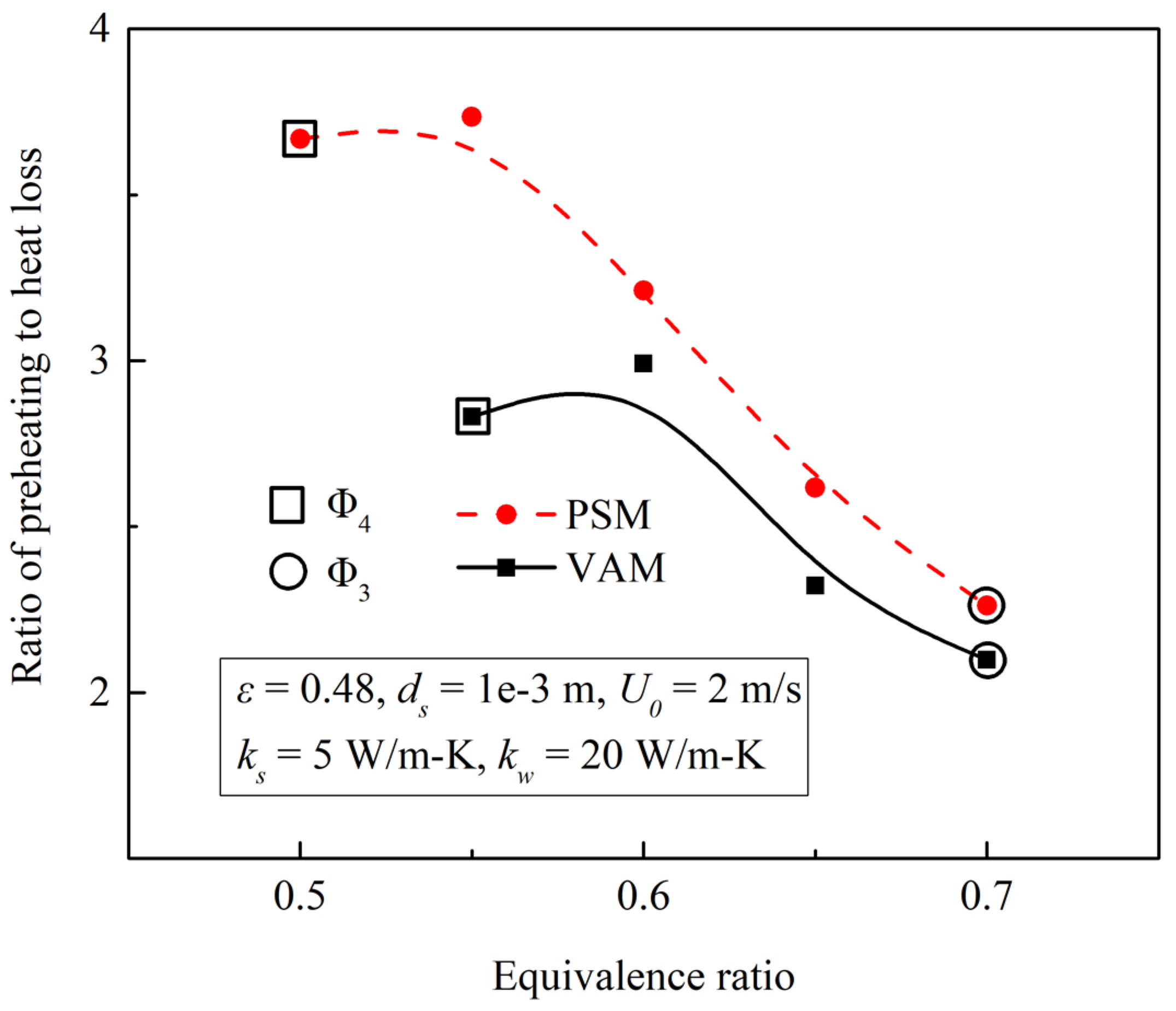
3.3.3. Ratio of Preheating to Heat Loss for VAM and PSM

In a porous micro-combustor, there are basically two preheating pathways for heat recirculation: one is the wall-to-gas preheating, differing from the macro-scale counterpart, and the other is the solid-to-gas preheating, as illustrated in Figure 8. It indicates that the fraction of solid-to-gas preheating (ηs−g) of the PSM combustor is obviously higher than its VAM counterpart, because the scattered reaction zone of the PSM combustor gives a larger interfacial area of heat transfer between solid matrix and gas. At the same time, the higher wall temperature of the PSM combustor results in the greater fraction of wall-to-gas preheating (ηw−g). Combining the two preheating pathways, the total preheating efficiency can be obtained, which is found that the fraction of overall preheating of the PSM combustor is larger than its VAM counterpart.
When the equivalence ratio changes from Φ4 to Φ3, the flame trends to be more upstream, thus the length (area) of the preheat zone decreases, which is believed to be the main reason for the reducing fraction of overall preheating for both PSM and VAM combustors.
The fraction of heat loss with a change in Φ is plotted in Figure 9 on the basis of the heat loss zone shown in Figure 6. A U-shaped curve was obtained for the VAM and PSM as the intention to increase the energy input rate would result in high heat loss. Figure 9 shows that the micro-combustors simulated using the PSM demonstrate a larger fraction of heat loss than the VAM counterpart. The multiple flame regions for the PSM indicate a larger flame area, and hence, more heat loss is understandable.
Based on our earlier paper, it is found that a ratio of preheating to heat loss, Rp-hl, is crucial to sustaining and stabilizing flames in a porous micro-combustor. The Rp-hl obtained by the PSM and VAM with U0 = 2 m/s are plotted in Figure 10, showing that a PSM combustor provides a larger Rp-hl. Therefore, combining the preheating and heat loss, the preheating effect of the PSM combustor is much better than the VAM, which is consistent with the rule that the PSM combustor gives a larger stability range. Figure 10 shows that Rp-hl of the PSM and VAM combustor decreases with the increase in Φ.
Interestingly, it is found that the trend varies, that is, when Φ is relatively low (∼Φ3 or bigger), there is a wide difference in the Rp-hl between the PSM and VAM combustor; when Φ is relatively high (in the order of Φ4), the difference of Rp-hl between the PSM and VAM decreases with the increase in Φ.
In view of the simulation results of Figure 5; Figure 10, it is deduced that in present configuration of porous micro-combustor, a smaller difference between two models can be obtained with a larger Φ. In other words, a PSM model with a larger Φ is more suitable to simplify as a VAM model.

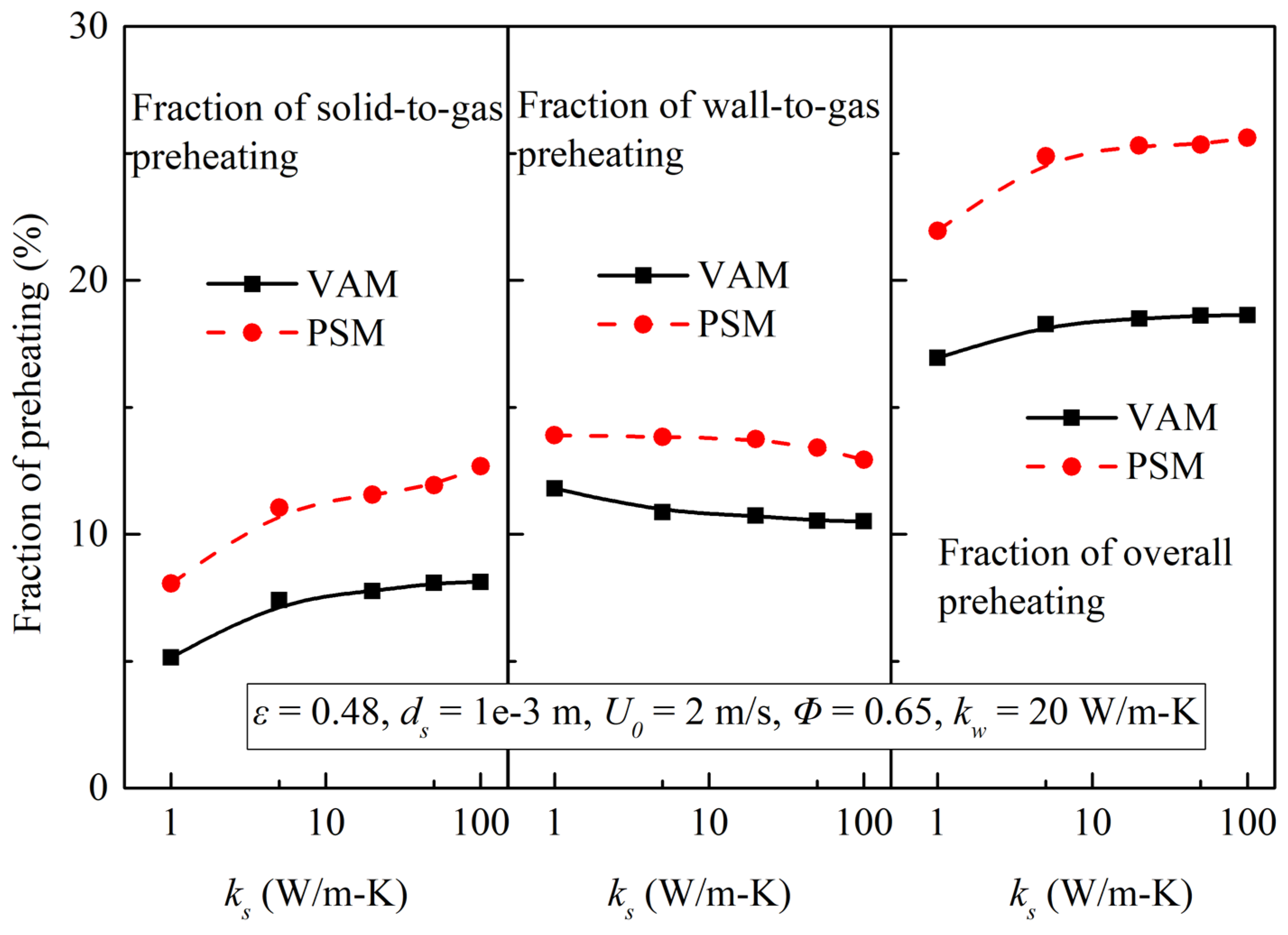
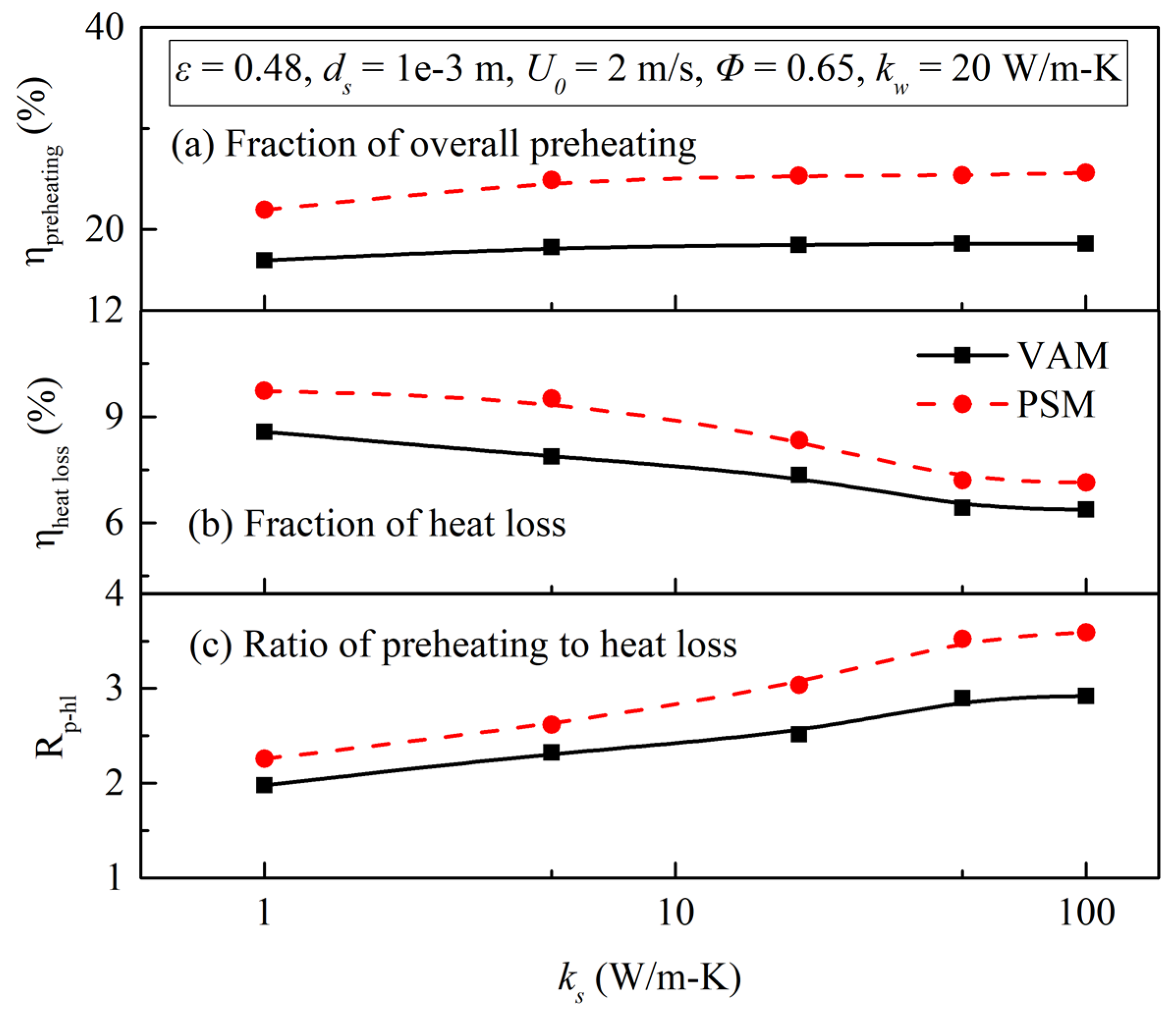
3.4. Effects of Solid Matrix Thermal Conductivity (ks)

Solid matrix thermal conductivity (ks) is an important parameter that influences the flame stability limit in a porous micro-combustor. By varying ks from 1 to 100 W/m-K, simulation results on the flame stability limits are calculated and shown in Figure 11. It is clearly shown that in the porous micro-combustor obtained by PSM, the flame stability range is obviously better than the VAM combustor. Another interesting observation drawn from Figure 11 is that Φ3 seems unaffected within the PSM and VAM calculation model, but interestingly, Φ4 exhibits a strong dependence on the PSM and VAM combustor. In other words, the calculated difference between the two models will increase with the increase in ks.
To further analyze the effects of ks, the variations of flame temperature, peak wall temperature and peak solid matrix temperature under the conditions (U0 = 2 m/s, Φ = 0.65, ε = 0.48, ds = 1 mm, kw = 20 W/m-K and ks = 1–100 W/m-K) are plotted in Figure 12. From Figure 5 in Section 3.2 and Section 3.4 we find that the PSM combustor gives a lower flame temperature and peak solid matrix temperature and a higher peak wall temperature than the VAM counterpart. Figure 12 further illustrates that this rule is almost independent of ks of the porous medium. Another rule can be found that when ks takes a much lower value (for example, ks = 1 W/m-K), the temperature difference (including flame temperature, peak wall temperature and peak solid matrix temperature) is much smaller, and the temperature difference will increase with the increasing ks in a nearly monotonic manner.
Figure 13 quantifies the effects of ks on two pathways of preheating; they are solid-to-gas preheating and wall-to-gas preheating. When the solid material is increased from 1 to 100 W/m-K, a better intensity of thermal conduction in both streamwise and transverse directions gives a higher fraction of solid-to-gas preheating. At the same time, the flame zone moves upstream with the increasing ks, resulting in a negative effect on the fraction wall-to-gas preheating. Combining these two effects, the fraction of overall preheating that increases with the increase in ks is understandable.
Based on the approach described in Section 3.3.3, effects of ks on fractions of preheating and heat loss and Rp-hl obtained by PSM and VAM are calculated, and the results are shown in Figure 14. For ks = 1~100 W/m-K, the fractions of preheating and heat loss and Rp-hl obtained by PSM are much larger than the VAM counterpart, which is consistent with the results of Figure 8, Figure 9 and Figure 10. Referring to Figure 14, a larger ks represents a smaller fraction of heat loss and a larger Rp-hl. It is clearly shown in Figure 14 that a smaller difference of Rp-hl between the PSM and VAM will be obtained with a smaller ks, and thus a smaller ks means a smaller calculation error in terms of Rp-hl when the PSM is simplified as the VAM.
Combining the model difference between the PSM and VAM in terms of flame stability limits, temperature profile and Rp-hl shown in Figure 11, Figure 12 and Figure 14, a specific conclusion can be found that the present configuration of PSM porous micro-combustor is more suitable for simplifying to a VAM with an extremely low ks value.

4. Conclusions

The purpose of this study was to develop a PSM in a structurally arranged porous medium made of discrete alumina spheres to produce a quantitatively accurate porous micro-combustor. A quantification study was undertaken to examine and systematically compare the heat recirculation, including preheating and heat loss, in the porous micro-combustor using the VAM and PSM. A pore-scale numerical model was developed in a structurally arranged porous medium made of discrete alumina spheres to better understand the coupling between the porous media and combustor wall. Experimental and numerical studies showed that the porous media allowed more effective heat recirculation through the solid matrix and combustor walls in the micro-/meso-scale. In addition, the combustion characteristics and flame stability limits of H2/air premixed combustion were examined. A parametric study is subsequently carried out to examine the effects of solid matrix thermal conductivity (ks) on the PSM and VAM, and then the results were analyzed briefly. Under the conditions (U0 = 2 m/s, Φ = 0.65, ε = 0.48, ds = 1 mm, kw = 20 W/m-K and ks = 1–100 W/m-K) considered in the present study, the following conclusions can be made from the simulation results:
(1)
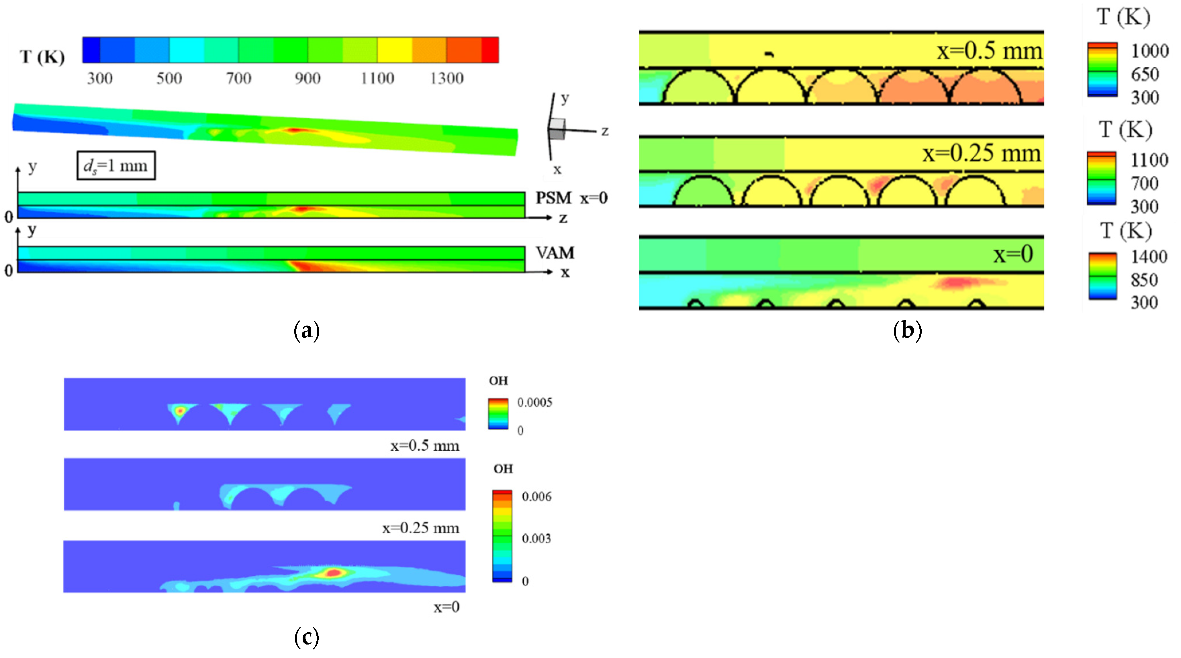
The VAM predicts a parabolic flame front and the highest temperature region at the centerline, but the PSM predicts a scattered flame zone in the pore areas;
(2)
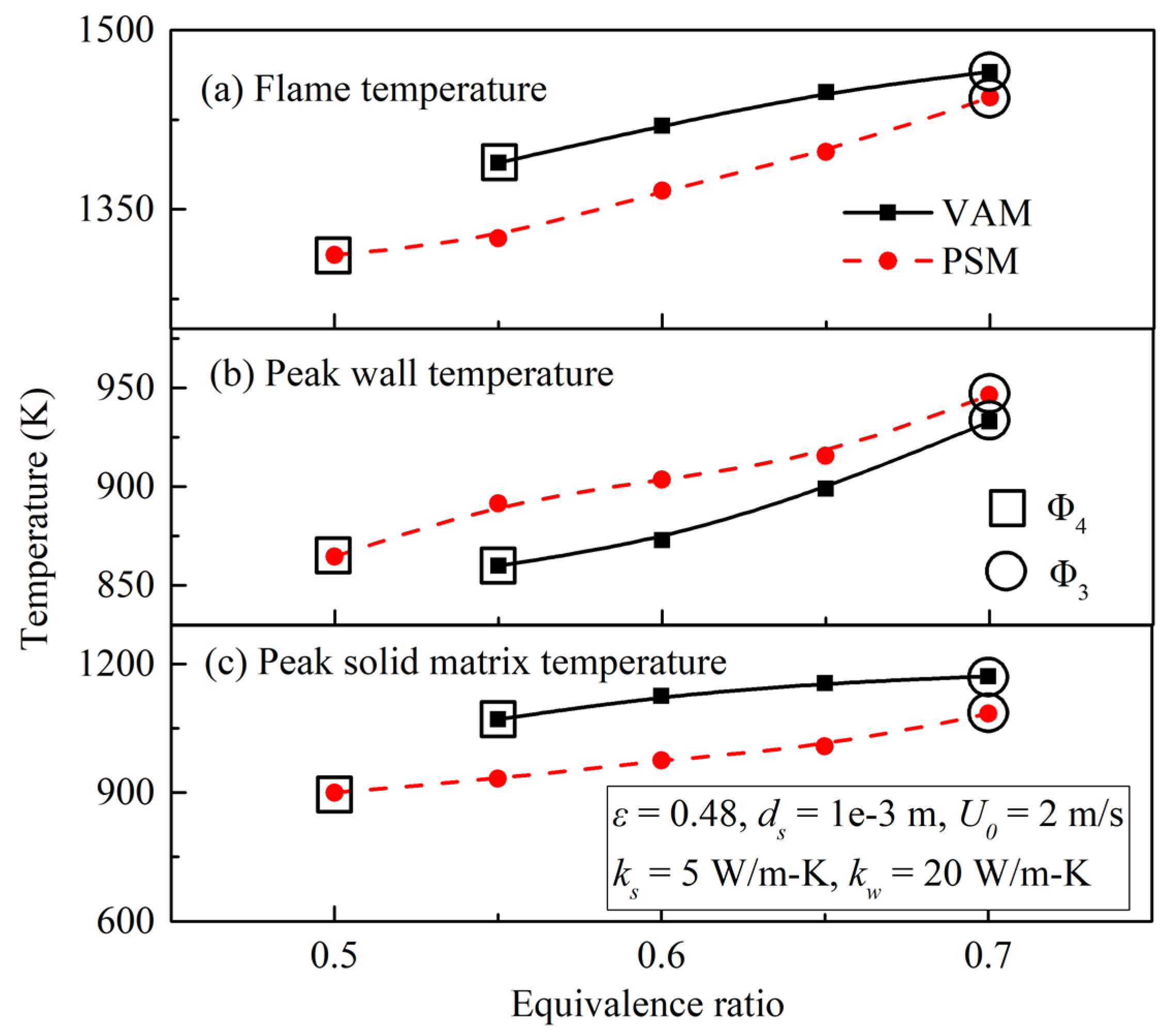
Under the same flow conditions and properties of porous medium, the PSM gives a larger flame stability range, a lower flame temperature and peak solid matrix temperature and a higher peak wall temperature than a VAM counterpart;
(3)
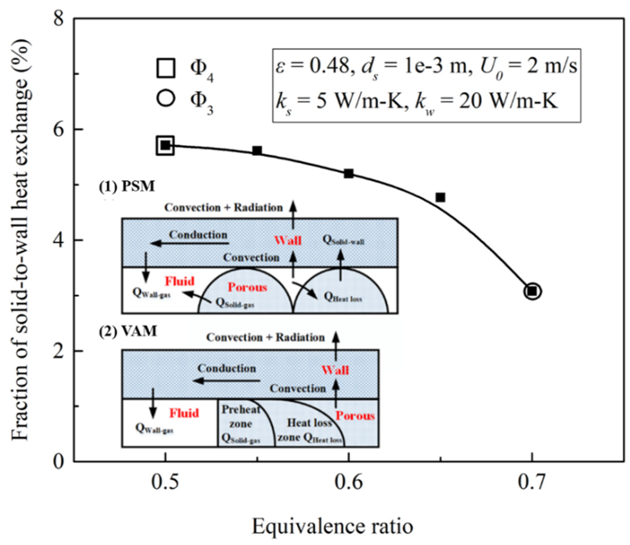
In the PSM combustor, solid-to-wall heat exchange (qs−w) between the solid matrix and wall decreases with the decrease in Φ;
(4)
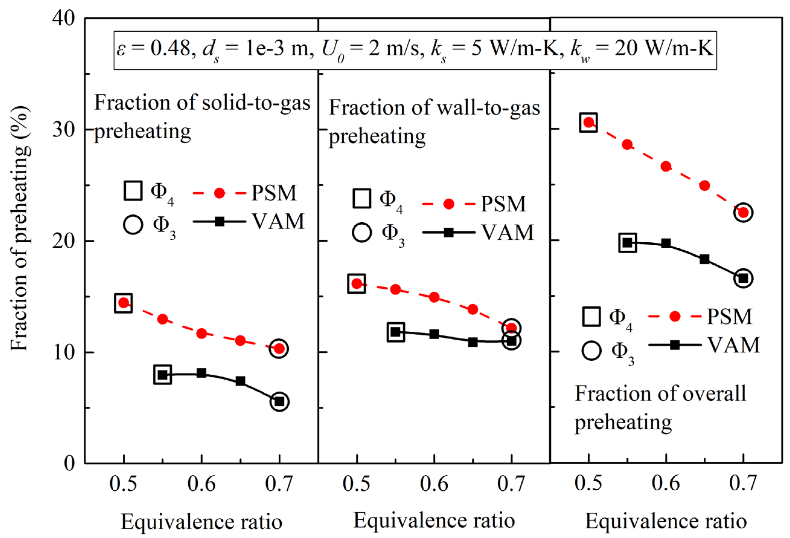
Ratio of preheating to heat loss (Rp-hl) of the PSM and VAM both decrease with the increase in Φ, and the PSM combustor provides a larger Rp-hl;
(5)
Under the same flow conditions and properties of porous media, the difference of temperature and Rp-hl between the PSM and VAM decreases with the increase in Φ, and the decrease in ks.
Therefore, the PSM porous micro-combustor is more suitable for simplifying to a VAM with a larger Φ and a smaller ks, which is only for specific configurations of a porous micro-combustor considered in the present study, and therefore it should be noted that the results in present paper are of limited applicability. However, the calculation and analysis methods in principle can be applied to other porous structure in micro-combustors as well, which is necessary to provide some qualitative guidance to the application of porous micro-combustors.

Author Contributions

Conceptualization, Q.L. and J.L.; methodology, Q.L. and J.L.; software, Q.L.; validation, Q.L. and J.S.; formal analysis, Q.L.; investigation, Q.L.; resources, J.L.; data curation, Q.L.; writing—original draft preparation, Q.L.; writing—review and editing, Q.L. and J.L.; visualization, Q.L.; supervision, J.W. and J.L.; project administration, J.L.; funding acquisition, J.L. All authors have read and agreed to the published version of the manuscript.

Funding

This research was funded by the National Natural Science Foundation of China (Grant No. 51776136).

Institutional Review Board Statement

Not applicable.

Informed Consent Statement

Not applicable.

Data Availability Statement

Not applicable.

Acknowledgments

The authors gratefully acknowledge the financial support provided by the National Natural Science Foundation of China (Grant No. 51776136).

Conflicts of Interest

The authors declare no conflict of interest.

Nomenclature

ApContact heat transfer area between the solid matrix and wall, m2
dsAlumina spheres diameter, m
DiDiffusion coefficient of the ith species into the mixture, m2/s
hConvective heat loss coefficient (non-insulated wall), W/m2-K
hvVolumetric heat transfer coefficient between solid and gas, W/m3-K
HCombustor height, m
kgThermal conductivity of gas mixture, W/m-K
ksThermal conductivity of solid matrix, W/m-K
kwThermal conductivity of wall, W/m-K
LCombustor length, m
nTotal number of the faces in the surface,
pPressure, Pa
qrSource term due to radiation, W/m2
qwHeat loss from non-insulated wall, W/m2
QHeat content of the reactive mixture, J
tWall thickness, m
T0Inlet flow temperature, K
TaAmbient temperature, K
TgGas mixture temperature, K
TiLocal temperature in the facet, K
TwWall temperature, K
TwoOuter wall temperature, K
T Averaged fluid or solid temperature, K
ugVelocity in x-direction, m/s
U0Inlet flow velocity, m/s
vgVelocity in y-direction, m/s
wgVelocity in z-direction, m/s
WCombustor width, m
WiMolecular mass of the ith species, kg/mol
YiMass fraction of the ith species, kg/kg
Greeks
εrEmissivity of non-insulated wall,
μDynamic viscosity, N-s/m2
ρgDensity of gas mixture, kg/m3
σStefan–Boltzmann constant, 5.67 × 10⁻⁸ W/m2-K4
ΦEquivalence ratio
ωiProduction rate of the ith species, kmol/m3-s
Acronyms
PSMPore-scale model
VAMVolume-averaged model

References

  1. Stazio, A.; Chauveau, C.; Dayma, G.; Dagaut, P. Oscillating flames in micro-combustion. Combust. Flame 2016, 167, 392–394. [Google Scholar] [CrossRef]
  2. Wan, J.; Fan, A. Effect of solid material on the blow-off limit of CH4 /air flames in a micro combustor with a plate flame holder and preheating channels. Energy Convers. Manag. 2015, 101, 552–560. [Google Scholar] [CrossRef]
  3. Yang, W.M.; Chou, S.K.; Shu, C.; Li, Z.W.; Xue, H. Development of microthermophotovoltaic system. Appl. Phys. Lett. 2002, 81, 5255–5257. [Google Scholar] [CrossRef]
  4. Fu, K.; Knobloch, A.J.; Cooley, B.A.; Walther, D.C.; Miyasaka, K. Microscale combustion research for applications to mems rotary ic engine. In Proceedings of the NHTC, 2001 National Heat Transfer Conference, Anaheim, CA, USA, 11–16 November 2001. [Google Scholar]
  5. Epstein, A.H.; Senturia, S.D. Macro power from micro machinery. Science 1997, 276, 1211. [Google Scholar] [CrossRef]
  6. Mehra, A.; Zhang, X.; Ayon, A.A.; Waitz, I.A.; Schmidt, M.A.; Spadaccini, C.M. A Six-Wafer Combustion System for a Silicon Micro Gas Turbine Engine. J. Microelectromech. Syst. 2000, 9, 517–527. [Google Scholar] [CrossRef]
  7. Yang, W.M.; Chou, S.K.; Shu, C.; Xue, H.; Li, Z.W. Development of a prototype micro-thermophotovoltaic power generator. J. Phys. D Appl. Phys. 2004, 37, 1017. [Google Scholar] [CrossRef]
  8. Zuo, W.; Zhao, X.; Jiaqiang, E.; Liu, X.; Peng, Q.; Liu, H. Numerical investigation on hydrogen/air non-premixed combustion in a three-dimensional micro combustor. Energy Convers. Manag. 2016, 124, 427–438. [Google Scholar]
  9. Vlachos, D.G.; Schmidt, L.D.; Aris, R. Ignition and extinction of flames near surfaces: Combustion of H2 in air. Combust. Flame 1993, 95, 313–335. [Google Scholar] [CrossRef]
  10. Li, J.; Chou, S.K.; Li, Z.W.; Yang, W.M. Characterization of wall temperature and radiation power through cylindrical dump micro-combustors. Combust. Flame 2009, 156, 1587–1593. [Google Scholar] [CrossRef]
  11. Yang, W.M.; Chou, S.K.; Shu, C.; Li, Z.W.; Xue, H. Combustion in micro-cylindrical combustors with and without a backward facing step. Appl. Therm. Eng. 2002, 22, 1777–1787. [Google Scholar] [CrossRef]
  12. Spadaccini, C.M.; Xin, Z.; Cadou, C.P.; Miki, N.; Waitz, I.A. Preliminary development of a hydrocarbon-fueled catalytic micro-combustor. Sens. Actuators A Phys. 2003, 103, 219–224. [Google Scholar] [CrossRef]
  13. Yan, Y.; Huang, W.; Tang, W.; Zhang, L.; Li, L.; Ran, J.; Yang, Z. Numerical study on catalytic combustion and extinction characteristics of pre-mixed methane–air in micro flatbed channel under different parameters of operation and wall. Fuel 2016, 180, 659–667. [Google Scholar] [CrossRef]
  14. Maruta, K.; Takeda, K.; Ahn, J.; Borer, K.; Deutschmann, O. Extinction limits of catalytic combustion in microchannels. Proc. Combust. Inst. 2002, 29, 957–963. [Google Scholar] [CrossRef] [Green Version]
  15. Li, D.B.; Xu, Q.S.; Shen, Y.L.; Wen, Z.Y.; Liu, Y.M. Experimental and Numerical Study of Premixed Combustion within Porous Media. Adv. Mater. Res. 2012, 557, 1572–1583. [Google Scholar] [CrossRef]
  16. Chou, S.K.; Li, Z.W.; Yang, W.M. Experimental investigation of porous media combustion in a planar micro-combustor. Fuel 2010, 89, 708–715. [Google Scholar]
  17. Li, J.; Wang, Y.; Chen, J.; Shi, J.; Liu, X. Experimental study on standing wave regimes of premixed H2–air combustion in planar micro-combustors partially filled with porous medium. Fuel 2016, 167, 98–105. [Google Scholar] [CrossRef]
  18. Chua, K.J.; Yang, W.M.; Ong, W.J. Fundamental Experiment and Numerical Analysis of a Modular Microcombustor with Silicon Carbide Porous Medium. Ind. Eng. Chem. Res. 2012, 51, 6327–6339. [Google Scholar] [CrossRef]
  19. Li, J.; Li, Q.; Wang, Y.; Guo, Z.; Liu, X. Fundamental flame characteristics of premixed H2–air combustion in a planar porous micro-combustor. Chem. Eng. J. 2016, 283, 1187–1196. [Google Scholar] [CrossRef]
  20. Barra, A.J.; Ellzey, J.L. Heat recirculation and heat transfer in porous burners. Combust. Flame 2004, 137, 230–241. [Google Scholar] [CrossRef]
  21. Jiang, L.; Liu, H.; Wu, D.; Wang, J.; Xie, M.Z.; Bai, M. Pore-scale SimulationofHydrogen-Air Premixed Combustion Processin Randomly Packed Beds. Energy Fuels 2017, 31, 12791–12803. [Google Scholar] [CrossRef]
  22. Eldesoky, I.M.; Abdelsalam, S.I.; Abumandour, R.M.; Kamel, M.H.; Vafai, K. Interaction between compressibility and particulate suspension on peristaltically driven flow in planar channel. Appl. Math. Mech. 2017, 38, 1–18. [Google Scholar] [CrossRef]
  23. Abdelsalam, S.I.; Sohail, M. Numerical approach of variable thermophysical features of dissipated viscous nanofluid comprising gyrotactic micro-organisms. Pramana 2020, 94, 1–12. [Google Scholar] [CrossRef]
  24. Kaviany, A. Nonequilibrium in the transport of heat and reactants in combustion in porous media. Prog. Energy Combust. Sci. 2001, 27, 523–545. [Google Scholar]
  25. Sahraoui, M.; Kaviany, M. Direct simulation vs volume-averaged treatment of adiabatic, premixed flame in a porous medium. Int. J. Heat Mass Transf. 1994, 37, 2817–2834. [Google Scholar] [CrossRef] [Green Version]
  26. Hackert, C.L.; Ellzey, J.L.; Ezekoye, O.A. Combustion and heat transfer in model two-dimensional porous burners. Combust. Flame 1999, 116, 177–191. [Google Scholar] [CrossRef]
  27. Jouybari, N.F.; Maerefat, M.; Nimvari, M.E. A pore scale study on turbulent combustion in porous media. Heat Mass Transf. 2016, 52, 269–280. [Google Scholar] [CrossRef]
  28. Bedoya, C.; Dinkov, I.; Habisreuther, P.; Zarzalis, N.; Parthasarathy, P. Combustion and Flame Experimental study, 1D volume-averaged calculations and 3D direct pore level simulations of the flame stabilization in porous inert media at elevated pressure. Combust. Flame 2015, 15, 41. [Google Scholar]
  29. Rabinovich, O.S.; Fefelov, A.V.; Pavlyukevich, N.V. Modeling of premixed gas combustion in porous media composed of Coarse-Sized particles: 1-D description with discrete solid phase. Symp. Combust. 1996, 26, 3383–3389. [Google Scholar] [CrossRef]
  30. Norton, D.G.; Vlachos, D.G. A CFD study of propane/air microflame stability. Combust. Flame 2004, 138, 97–107. [Google Scholar] [CrossRef]
  31. Kang, X.; Veeraragavan, A. Experimental investigation of flame stability limits of a mesoscale combustor with thermally orthotropic walls. Appl. Therm. Eng. 2015, 85, 234–242. [Google Scholar] [CrossRef]
  32. Veeraragavan, A.; Cadou, C.P. Flame speed predictions in planar micro/mesoscale combustors with conjugate heat transfer. Combust. Flame 2011, 158, 2178–2187. [Google Scholar] [CrossRef]
  33. Li, J.; Li, Q.; Shi, J.; Liu, X.; Guo, Z. Numerical study on heat recirculation in a porous micro-combustor. Combust. Flame 2016, 171, 152–161. [Google Scholar] [CrossRef]
  34. Veeraragavan, A. On flame propagation in narrow channels with enhanced wall thermal conduction. Energy 2015, 93, 631–640. [Google Scholar] [CrossRef]
  35. Leach, T.T.; Cadou, C.P. The role of structural heat exchange and heat loss in the design of efficient silicon micro-combustors. Proc. Combust. Inst. 2005, 30, 2437–2444. [Google Scholar] [CrossRef]
  36. Li, Q.; Wang, J.; Meng, L.; Li, J.; Guo, Z. CFD study on stability limits of hydrogen/air premixed flames in planar micro-combustors with catalytic walls. Appl. Therm. Eng. 2017, 121, 325–335. [Google Scholar] [CrossRef]
  37. Zhao, P.H.; Zhu, M.M.; Zhang, G.X.; Chen, Y.L.; Jiang, H. Numerical investigation of premixed combustion within a two-layer porous burner. Chin. J. Comput. Phys. 2006, 6, 427–439. [Google Scholar]
  38. Dixon, A.G.; Nijemeisland, M.; Stitt, E.H. Systematic mesh development for 3D CFD simulation of fixed beds: Contact points study. Comput. Chem. Eng. 2013, 48, 135–153. [Google Scholar] [CrossRef]
  39. Li, Q.; Li, J.; Shi, J.; Guo, Z. Effects of heat transfer on flame stability limits in a planar micro-combustor partially filled with porous medium. Proc. Combust. Inst. 2018, 37, 5645–5654. [Google Scholar] [CrossRef]
  40. Shi, J.; Xiao, H.; Li, J.; Li, N.; Xia, Y.; Xu, Y. Two-Dimensional Pore Level Simulation of Low-Velocity Filtration Combustion in a Packed Bed with Staggered Arrangements of Discrete Cylinders. Combust. Sci. Technol. 2017, 189, 1260–1276. [Google Scholar] [CrossRef]
  41. Wan, J.; Fan, A.; Yao, H.; Liu, W. A non-monotonic variation of blow-off limit of premixed CH4/air flames in mesoscale cavity-combustors with different thermal conductivities. Fuel 2015, 159, 1–6. [Google Scholar] [CrossRef]
  42. Wan, J.; Fan, A.; Yi, L.; Hong, Y.; Zhao, D. Experimental investigation and numerical analysis on flame stabilization of CH4/air mixture in a mesoscale channel with wall cavities. Combust. Flame 2010, 50, 639–642. [Google Scholar] [CrossRef]
  43. Inc, F. FLUENT 6.3 User’s Guide; Fluent Inc.: Lebanon, NH, USA, 2006. [Google Scholar]
  44. Bubnovich, V.; Henríquez, L.; Gnesdilov, N. Numerical Study of the Effect of the Diameter of Alumina Balls on Flame Stabilization in a Porous-Medium Burner. Numer. Heat Transf. 2007, 52, 275–295. [Google Scholar] [CrossRef]
  45. Koester, Z. Superadiabatic combustion of methane air mixtures under filtration in a packed bed. Combust. Flame 1995, 100, 221–231. [Google Scholar]
Figure 1. Illustration of porous micro-combustor in the PSM. (a) Physical model; (b) channel along the spheres.
Applsci 11 07496 g001
Figure 2. Mesh generation. (a) Result of grid independence test obtained by the PSM, U0 = 2 m/s, Φ = 0.65, ds = 1 mm, ε = 0.48, ks = 5 W/m-K, and kw = 20 W/m-K; (b) local representation of the mesh with 357,355 nodes (ds = 1 mm).
Applsci 11 07496 g002
Figure 3. Model validation.
Applsci 11 07496 g003
Figure 4. Temperature distribution and OH concentration obtained by the VAM and PSM, with U0 = 2 m/s, Φ = 0.65, and ds = 1.0 mm. (a) Local temperature distribution obtained by the VAM and PSM; (b) temperature distribution obtained by the PSM; (c) OH concentration obtained by the PSM.
Applsci 11 07496 g004
Figure 5. Comparison of temperature obtained by the PSM and VAM.
Applsci 11 07496 g005
Figure 6. Delineation of solid-to-gas preheat zone and heat loss zone obtained by the PSM, with U0 = 2 m/s and Φ = 0.65.
Applsci 11 07496 g006
Figure 7. Fraction of solid-to-wall heat exchange (ηs−w) obtained by the PSM.
Applsci 11 07496 g007
Figure 8. Fraction of preheating obtained by the PSM and VAM.
Applsci 11 07496 g008
Figure 9. Fraction of heat loss obtained by the PSM and VAM.
Applsci 11 07496 g009
Figure 10. Variation of Rp-hl obtained by the PSM and VAM.
Applsci 11 07496 g010
Figure 11. Effects of ks on the flame stability limits obtained by the PSM and VAM.
Applsci 11 07496 g011
Figure 12. Effects of ks on the temperature obtained by the PSM and VAM.
Applsci 11 07496 g012
Figure 13. Effects of ks on the fraction of preheating obtained by the PSM and VAM.
Applsci 11 07496 g013
Figure 14. Effects of ks on the ratio of preheating to heat loss obtained by the PSM and VAM.
Applsci 11 07496 g014
Publisher’s Note: MDPI stays neutral with regard to jurisdictional claims in published maps and institutional affiliations.

