1. Introduction
Post-installed bonded anchors are commonly used for steel to concrete connections and offer flexibility compared to other anchor types due to their range of embedment depths and relatively smaller required edge distances and spacings. Bonded anchors transfer tensile load to concrete through adhesive bond and friction, exhibiting the following possible tensile failure modes: concrete cone, steel, anchor pull-out (bond), and concrete splitting [
1,
2]. Many bonded anchors can be designed to similar or higher strengths than most post-installed mechanical anchors at ambient temperature. However, bonded anchors are sensitive to several environmental factors [
3,
4,
5,
6]. To address these sensitivities, the assessment of bonded anchors in European [
7] and American guidelines [
8] requires tests on different anchor geometries accounting for dry and wet concrete, minimum curing time, freeze/thaw conditions, high alkalinity, sulphurous atmosphere, installation in insufficiently clean holes, installation in freezing conditions, and in-service temperatures. Accidents involving bonded anchors [
9,
10] have underscored the importance of proper testing, assessment, design, and installation protocols for these systems. The mechanical properties of adhesive resins are particularly temperature dependent [
11]. Under fire conditions, research studies [
12,
13] have shown that bond failure occurs more frequently than other failure modes for common ranges of bonded anchor diameter and embedment due to exceedance of glass transition temperatures and material softening. As with other sensitivities, use of bonded anchors in cases where fire ratings are required must be accompanied by proper assessment and design procedures.
Current assessment and design guidelines do not offer evaluation and design methods for bonded anchors under fire conditions [
7,
14]. Existing guidelines in the European Assessment Document (EAD) 330087 [
15] for post-installed reinforcement (PIR), however, provide criteria to produce bond stress vs. temperature curves for adhesives at high temperature expected during fire events. In these guidelines, a temperature response curve is obtained by a minimum of 20 tests on 12 mm diameter reinforcing bars installed with 120 mm embedment depths in confined concrete cylinders. After curing of the adhesive, tests are subjected to different magnitudes of constant load and increasing temperature until failure. The resulting curve allows design of PIR under fire conditions using Pinoteau’s bond strength resistance integration method (RIM) [
16]. The load-bearing capacity of the PIR connection is calculated using temperature profiles along the embedment depth for fire design, which is normally determined through numerical calculation. Using the bond stress vs. temperature curve of the adhesive, resistance contributions associated with the temperatures along the length of the connection can be integrated into an overall connection-resistance specific to temperature profiles. For standard fire conditions where the required capacity and temperature distributions during fire exposure are known, the time to failure of the connection can be calculated.
The steps of the resistance integration method were established first by Pinoteau et al. [
16] and validated on a large-scale test at the fire resistance laboratory at the Centre Scientifique et Technique du Bâtiment (CSTB) on cantilever-wall connection using PIRs under ISO 843-1 fire conditions [
17]. Another large-scale validation was performed at CSTB on a slab-wall connection under ISO 843-1 fire conditions by Lahouar et al. [
18]. Lahouar et al. [
19] also proposed a non-linear shear-lag model taking into account the displacement compatibility of PIR at high temperature (unaccounted for in RIM). Both approaches yielded accurate predictions of fire resistance durations of cantilever connections. Reichert and Thiele [
20] also attempted to adapt the method for bonded anchors under fire conditions using axisymmetric thermal modelling of the anchors, yielding conservative design values compared to fire tests. Lakhani and Hofmann [
16,
21] presented RIM results based on 2D thermal modelling of anchors, yielding higher design capacities than fire tests in some cases (e.g., bonded anchors with insulated fixtures). Al-Mansouri et al. [
22] validated RIM for the design of bonded anchors by investigating the parameters influencing fire tests on bonded anchors (fixtures, insulation conditions, concrete member thicknesses). The case of an anchor directly exposed to fire (i.e., using a metallic fixture and without insulating material) was identified as the most conservative testing condition [
23]. Al-Mansouri et al. based the RIM on 3D thermal modelling and the example of M12 rods with 110 mm embedment depth yielding conservative design values compared to fire tests.
In Reichert and Thiele [
20], ISO 834-1 fire tests were conducted on bonded anchors in uncracked concrete using two adhesives (one epoxy and one cementitious) and a large combination of configurations for anchor sizes from M10 to M30. Their design calculations, based on 2D axisymmetric transient heat transfer, yielded conservative results for most of the cases, but for some cases the calculation yielded higher resistances compared to fire tests. At CSTB, a study was conducted on the thermal influence of testing conditions on the resulting load-bearing capacity of bonded anchors (one epoxy adhesive) under fire conditions. This study is completed on the same adhesive in this paper with loaded fire tests on two different anchor geometries (M8 and M12). Both testing campaigns were performed according to the general requirements of fire tests according to [
24]. This standard gives a heating curve to be applied inside the furnace (i.e., measured temperature of hot gas inside the furnace during heating). The heating curve is derived from the ISO 834-1 standard [
17].
The objective of this paper is to regroup the data from Al-Mansouri et al. [
22,
23] and Reichert and Thiele [
20] to reevaluate the calculation method (based on 3D transient heat transfer and Eurocode material properties for steel [
25] and concrete [
26,
27]) in order to test its sensitivity to the bond stress vs. temperature relationship adopted in the RIM process. The aim is to extend the validity of RIM method for the design of bonded anchors under fire conditions for all anchor sizes and propose recommendations for the evaluation method consistent with Eurocode design requirements. The same methodology for determining bond stress vs. temperature curves for PIR in EAD 330087 is applied to bonded anchors using threaded rods. Unlike PIR, bonded anchors are not protected by a concrete cover and are directly exposed to fire, resulting in significantly higher temperatures transmitted through the steel element. The modified evaluation method is therefore assessed in this paper for bond stress vs. temperature curves with the expectation of higher temperatures. The extension of the curve should be based only on test results up to a maximum temperature respecting the 3 h and 5 °C/min heating rate (imposed on the exterior of the specimen) in EAD 330087. To assess the beneficial effect (increase of calculated pull-out resistance of the bonded anchor) of accounting for this extension of the bond stress vs. temperature curve, a study was conducted based on the presented calculations in this paper.
2. Description of Test Campaigns and Properties of the Materials
The testing campaigns in Al-Mansouri et al. [
22,
23] and Reichert and Thiele [
20] were conducted at Technical Universität Kaiserslautern (TU Kaiserslautern), Germany and CSTB in Paris, France, respectively. This section describes the configuration of fire tests on bonded anchors adopted by TU Kaiserslautern and CSTB. In addition, relevant material properties are presented.
2.1. Description of Fire Tests
Fire tests were conducted at TU Kaiserslautern and CSTB according to the specifications of EOTA TR 020 [
14]. Bonded anchors were installed according to manufacturers’ instructions and loaded with varying degrees of constant tensile load at ambient temperatures. The fire scenario applied in the furnace on test specimens was ISO 834-1 [
17] until anchor failure. For each test, a fire resistance in terms of load and failure time were reported for the failed anchor.
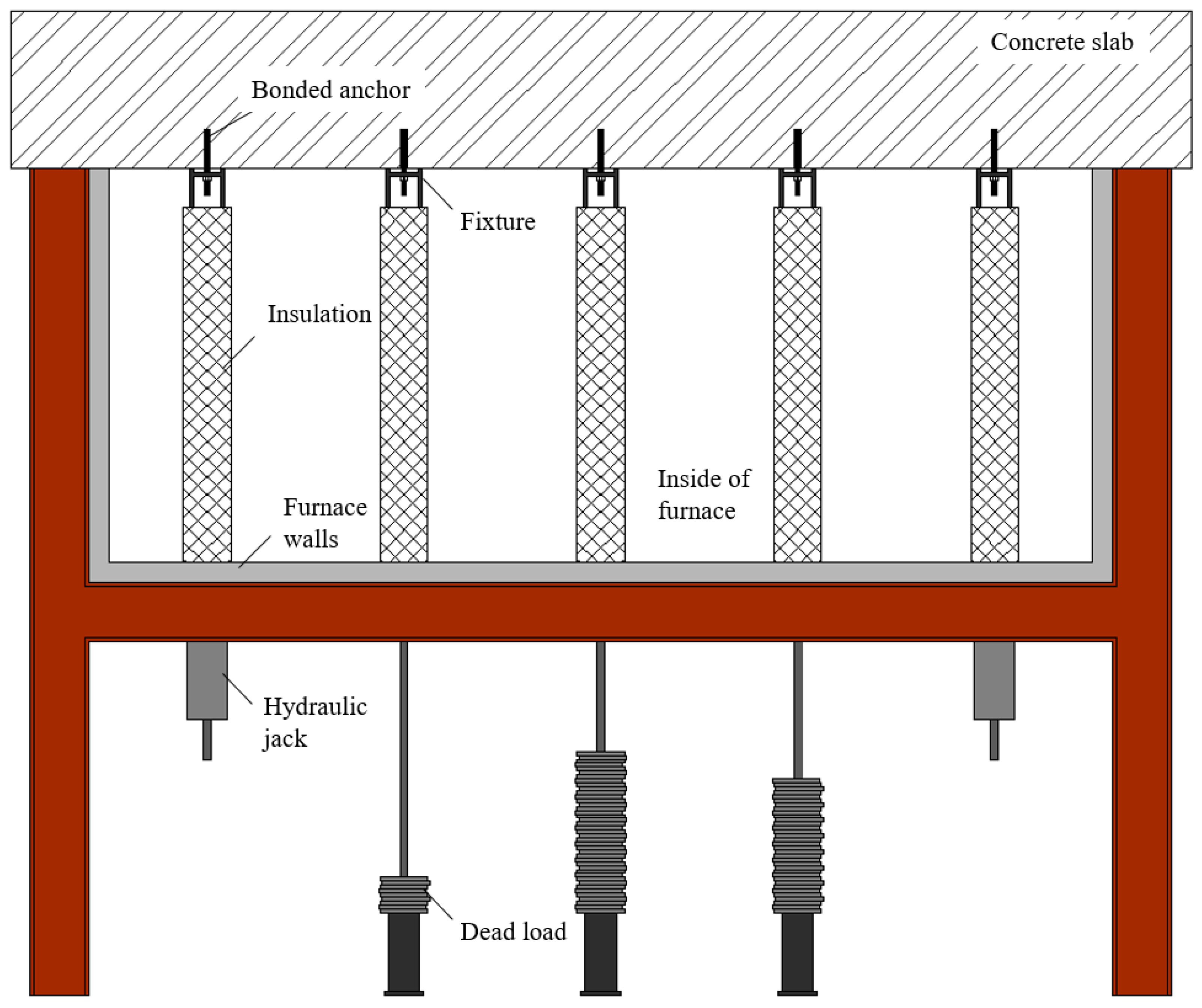
Testing conditions in both campaigns were similar, with slight differences in the load transfer system and concrete bearing elements. The TU Kaiserslautern approach consisted of loading the anchors (installed in slabs) by dead load or hydraulic jacks at the bottom (exterior) of the furnace, connected to the anchor with the help of a steel arm and a metallic fixture (
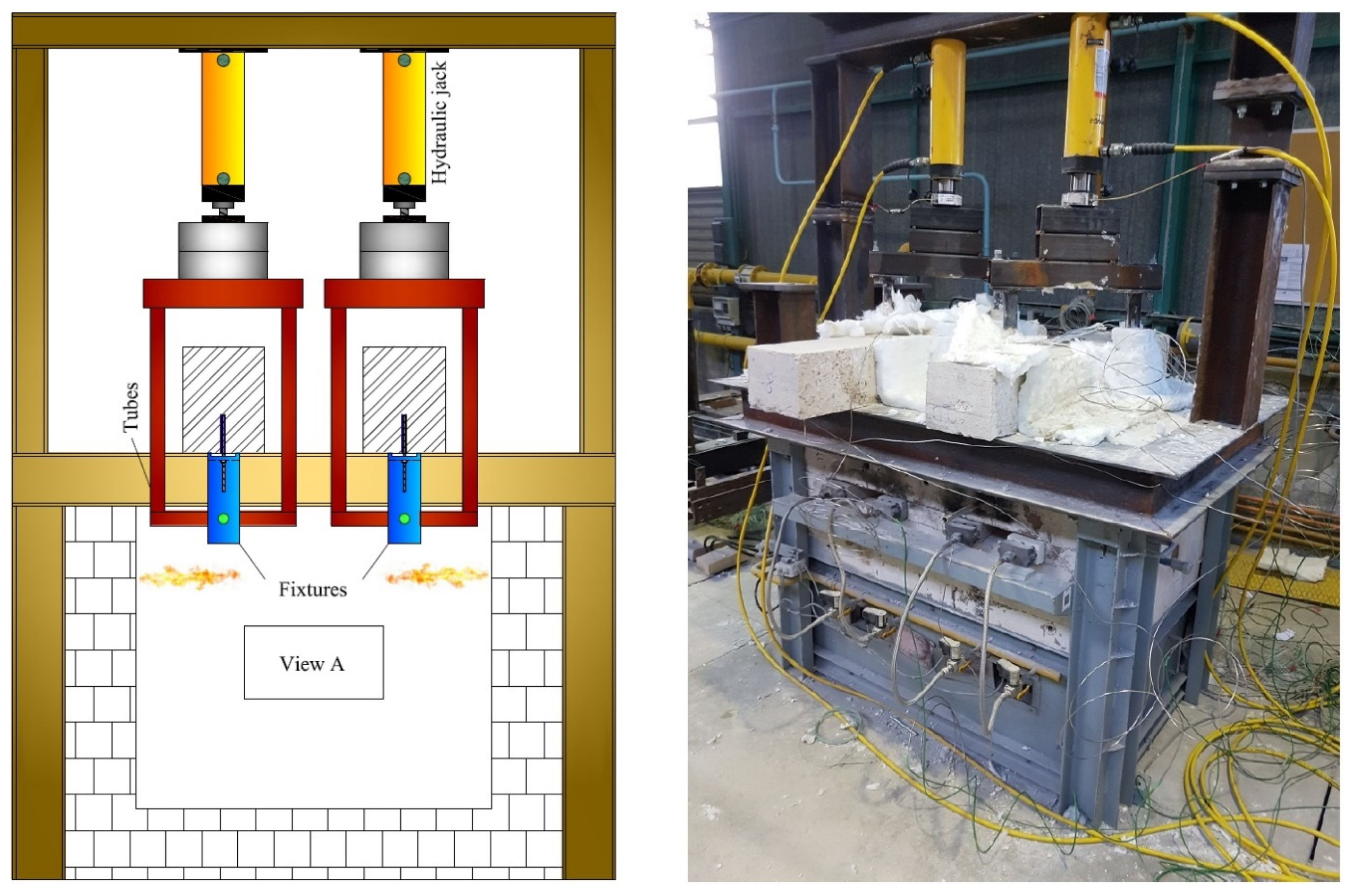
Figure 1). The CSTB approach consisted of loading the anchors (installed in beams) using a metallic frame connected to the fixture of the anchor inside the furnace and to a hydraulic jack outside the furnace (
Figure 2).
In a previous experimental work [
23], Al-Mansouri et al. investigated the influence of the loading system on temperature profiles and resulting load-bearing capacity of bonded anchors and found it negligible. Details of load-transfer fixtures were adopted from EOTA TR 020 [
14] depending on the applied load of the anchor.
2.2. Summary of Tested Materials and Test Results
TU Kaiserslautern’s test campaign contained tests on two adhesives. The first adhesive was an epoxy resin (named mortar B in their report and referred to as Adhesive-1 henceforth), and the second adhesive was a cementitious mortar (called mortar C in their report and referred to as Adhesive-2 henceforth). CSTB’s test campaign was on one epoxy resin (referred to as Adhesive-3 henceforth).
2.3. Prediction of the Load-Bearing Capacity Using Pinoteau’s Resistance Integration Method (RIM) and 3D Thermal Modelling of the Anchor
The numerical model [
22] is based on the following analytical procedures:
The bonded anchor adhesive is not modeled,
Steel threads are not modeled (i.e., cylindrical geometry for the anchor rod),
The concrete remains uncracked,
Concrete spalling is ignored,
The fire exposed surface of all elements is subjected to convective and radiative fluxes of ISO 834-1 fire temperatures [
17] on all sides,
The unexposed fire surface of concrete beams is subjected to convective and radiative fluxes of ambient air at 20 °C, and
Slip of anchors is ignored.
During a fire test, heat transfer from hot gas inside the furnace to the exposed elements occurs via convection and radiation. Inside the members, conduction transfers the heat from the fire exposed surface inside the elements towards the unexposed surface. This problem can be solved by finite element modelling using ANSYS with the governing differential equation for 3D transient heat conduction using the implicit scheme and iterative solver expressed in Equation (1):
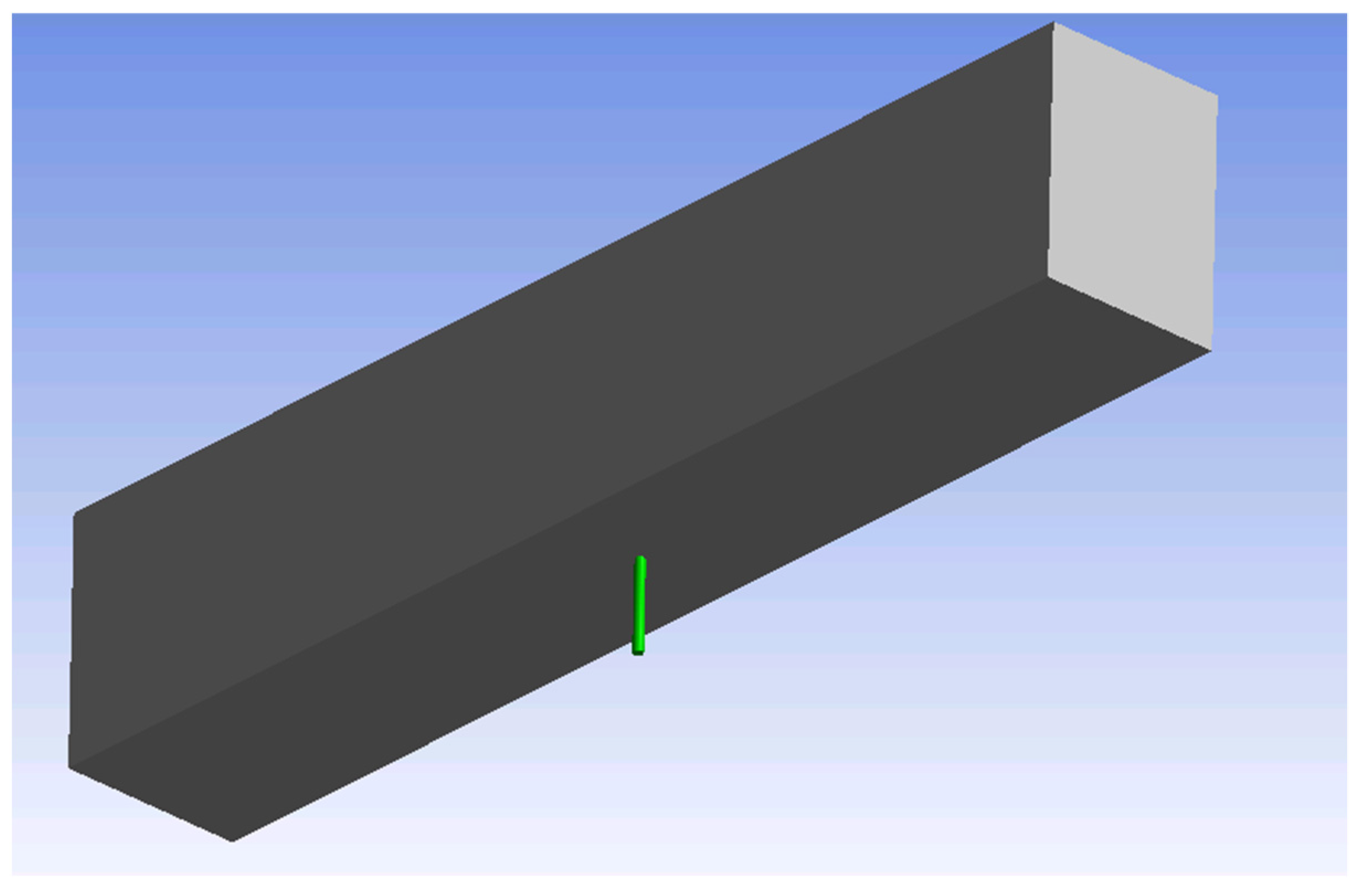
The 3D model represents the anchor as a cylinder inside of a concrete bearing element with modelling of the extended and embedded length of the steel anchor element (
Figure 3).
Equation (2) describes the Neumann boundary condition satisfied at the fire-exposed surface:
Equation (3) describes the Neumann boundary condition satisfied at the upper surface of the concrete bearing element exposed to ambient air at 20 °C:
where:
is the total heat flux applied to the exposed surface,
is the thermal conductivity (W/m·K),
is the mass density (kg/m3),
is the specific heat (J/kg·K),
is the convective heat transfer coefficient for the fire exposed surface (25 W/m2·K),
is the convective heat transfer coefficient for the surface exposed to air at 20 °C (4 W/m2·K),
is the Boltzmann constant (5.667 × 10⁻⁸ W/m2·K4),
is surface emissivity (0.7),
is the solid surface temperature (K),
is gas temperature inside the furnace as a function of time (K),
is ambient air temperature (293 K), and
is time.
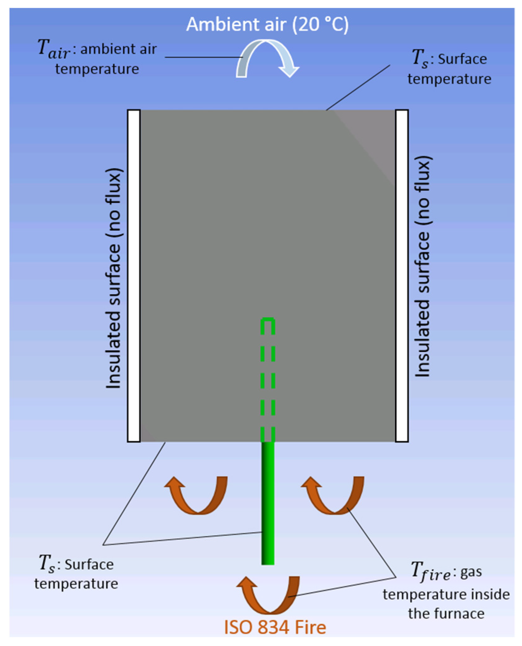
Boundary conditions are represented in a profile view of the 3D model in
Figure 4.
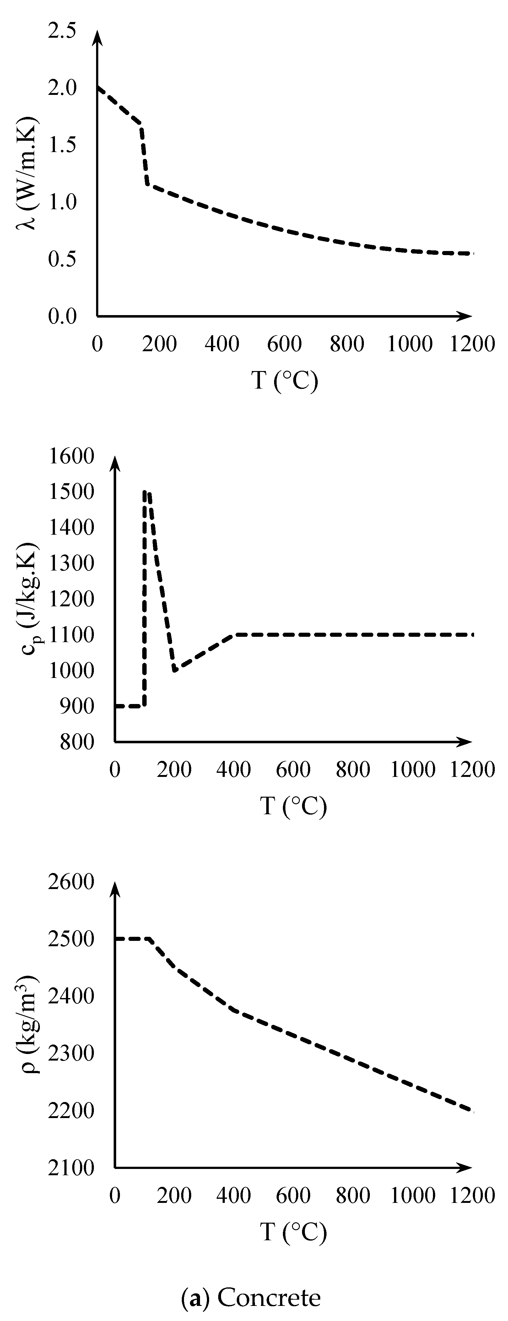
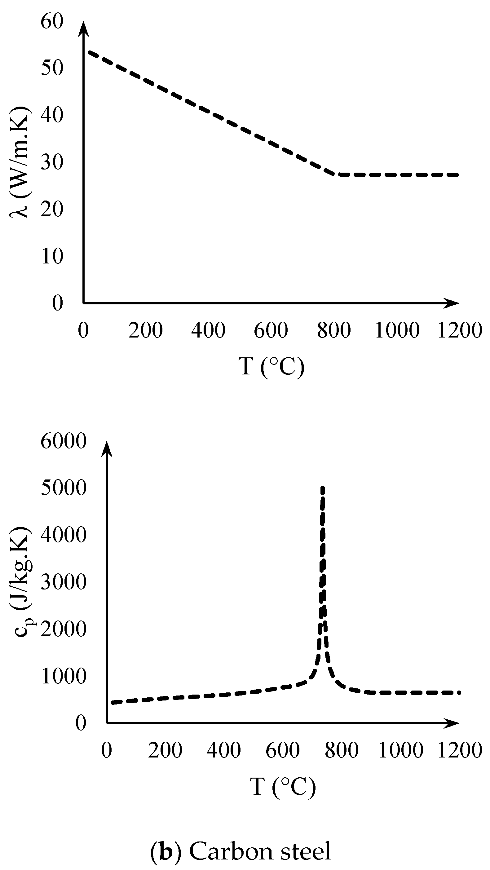
The thermal properties of concrete and carbon steel (conductivity, specific heat and mass density) are a function of temperature. The properties according to the French national annex in Eurocode 2 [
26] for both materials are adopted in this study (
Figure 5). The mass density of the steel (7850 kg/m
3) [
25] is considered constant with respect to temperature.
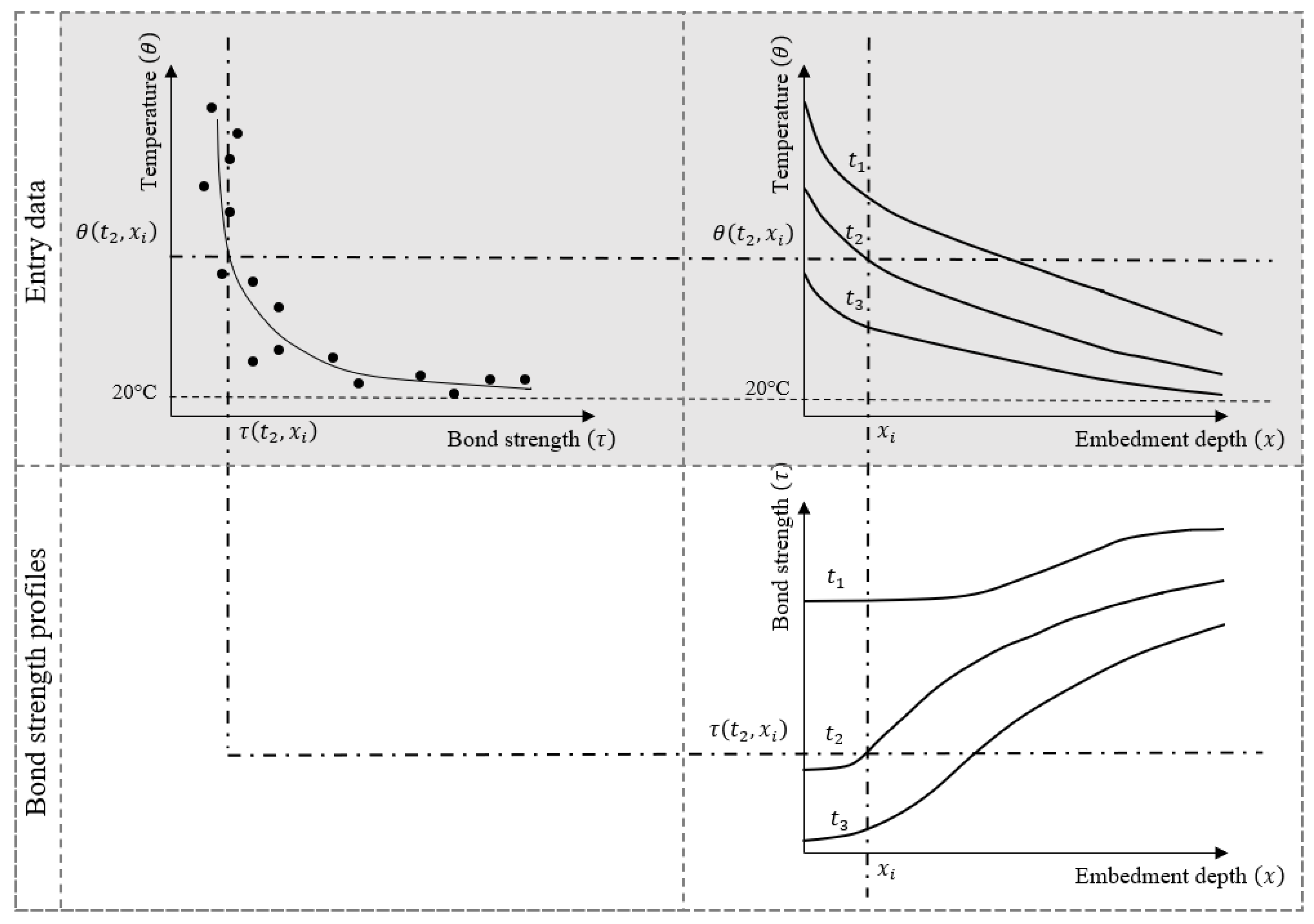
Knowing the thermal distribution along the anchor at each moment of heating, it is possible to associate a resistance to each temperature using the resistance-temperature relationship. Pinoteau [
16] illustrated schematically how the resistance at a depth
is determined at a time
based on the thermal distribution (
Figure 6).
This method allows the evolution of the load-bearing capacity of the bonded anchor during heating to be determined. Knowing the applied mechanical force on the anchor during heating, failure time under fire conditions can be determined.
The bond capacity of the anchor at any given time is calculated according to Equation (4):
where:
is the pull-out resistance of the anchor under fire conditions (N),
is the diameter of the anchor (mm),
is the mean bond resistance of the anchor at ambient temperature in uncracked concrete (N/mm2),
is a reduction factor that depends on temperature,
is the temperature distribution along the embedment depth of the anchor, and
is the embedment depth of the anchor (mm).
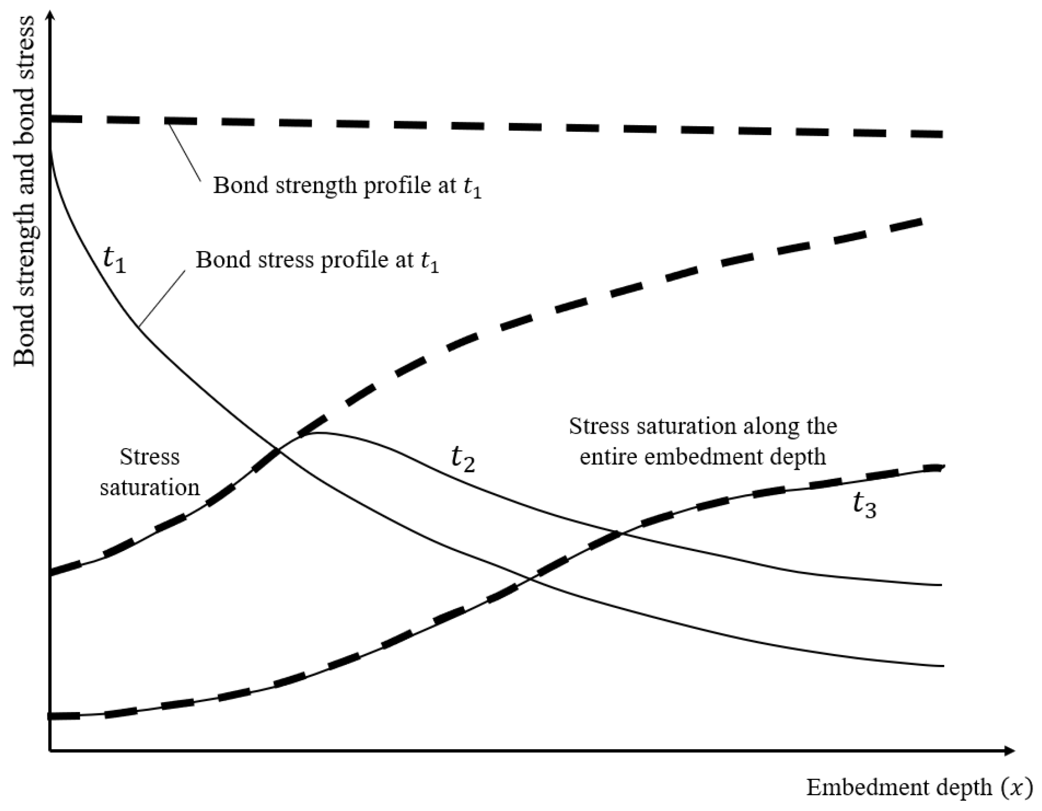
By integrating the resistances, this method does not take into account the stress distribution along the anchor. When a tensile force is applied on the anchor, a distribution of bond stresses occurs in a phenomenon called “shear-lag”. This stress profile is equal or lower than the resistance profile. When temperature increases under a constant mechanical load, the sum (integration) of the stress profile decreases until it reaches a maximum bond stress value at a certain depth. The saturation of bond stresses at certain depths leads to a redistribution of these stresses towards the deeper parts of the anchor where the stress is still less than the resistance. The area under the stress profile remains unchanged in a way to ensure the integrity of the anchor. Pull-out failure occurs when all the stresses along the anchor saturate, in this case the stress profile is equal to the resistance profile. Therefore, this justifies the determination of the load-bearing capacity by only considering the resistances (Equation (4)).
Figure 7 illustrates the evolution of temperature and bond stress profiles at three different times during heating
,
and
. Stress profiles are represented for a constant load applied at
(head of the anchor), and temperature profiles are represented for a non-uniform heating applied near
. At
(low temperatures), the stress profile is lower than the resistance profile because the temperature profile is still at low temperatures. At
(higher temperatures), heating at the head of the anchor decreases the resistance profile and leads to a saturation of stresses. At
(near failure point), all the stresses along the embedment depth have saturated and pull-out occurs if the temperature continues to increase.
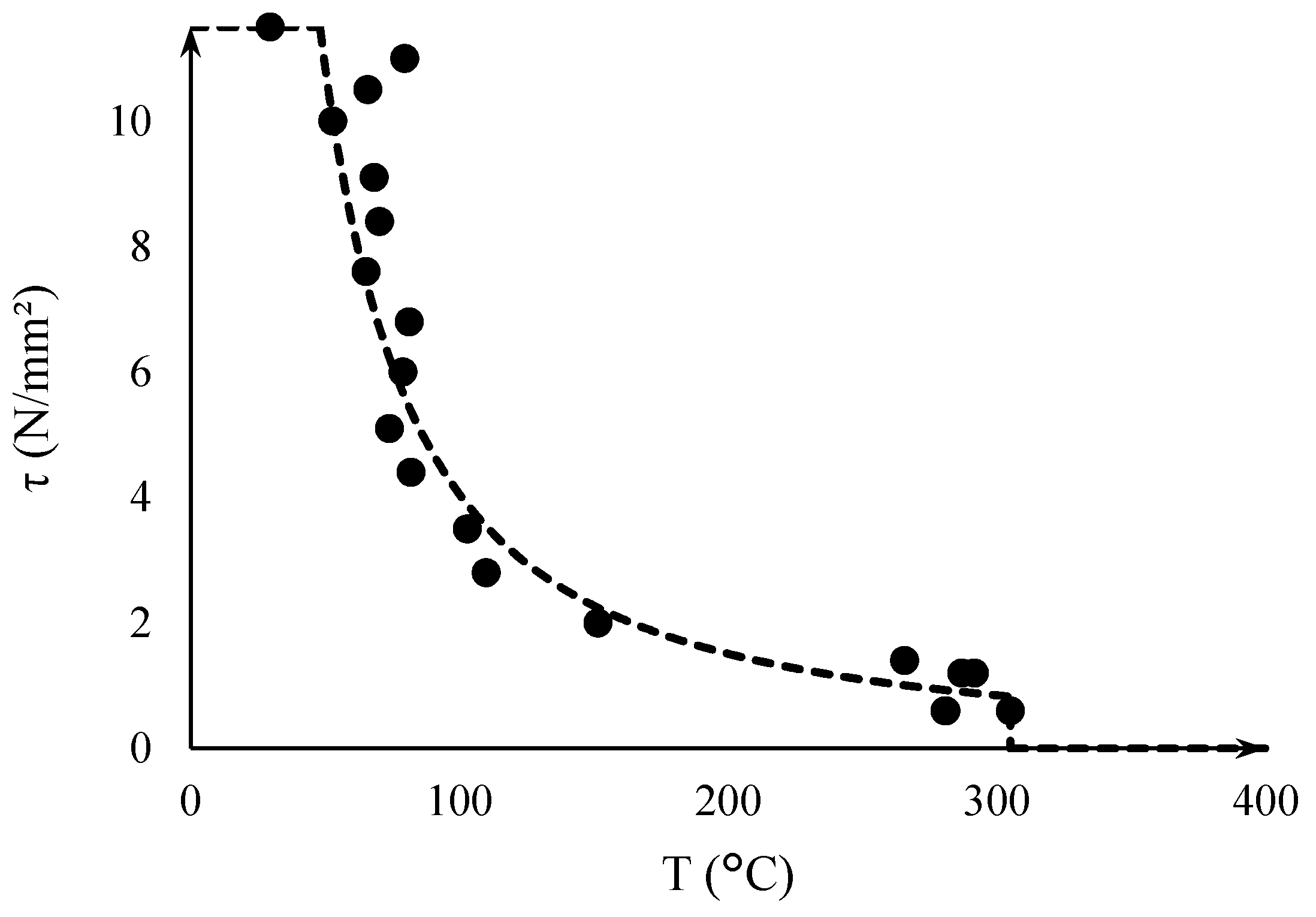
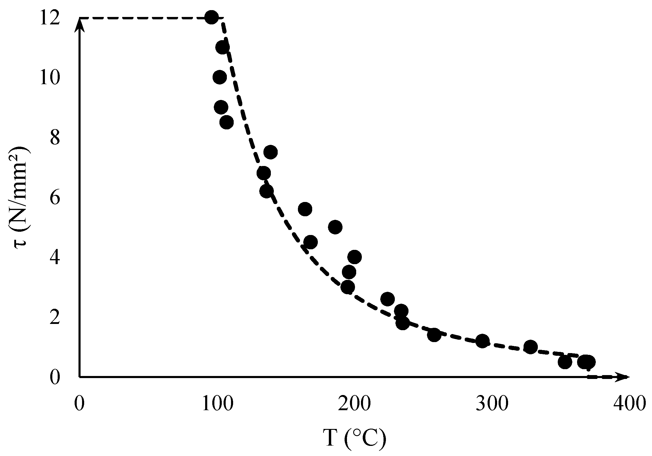
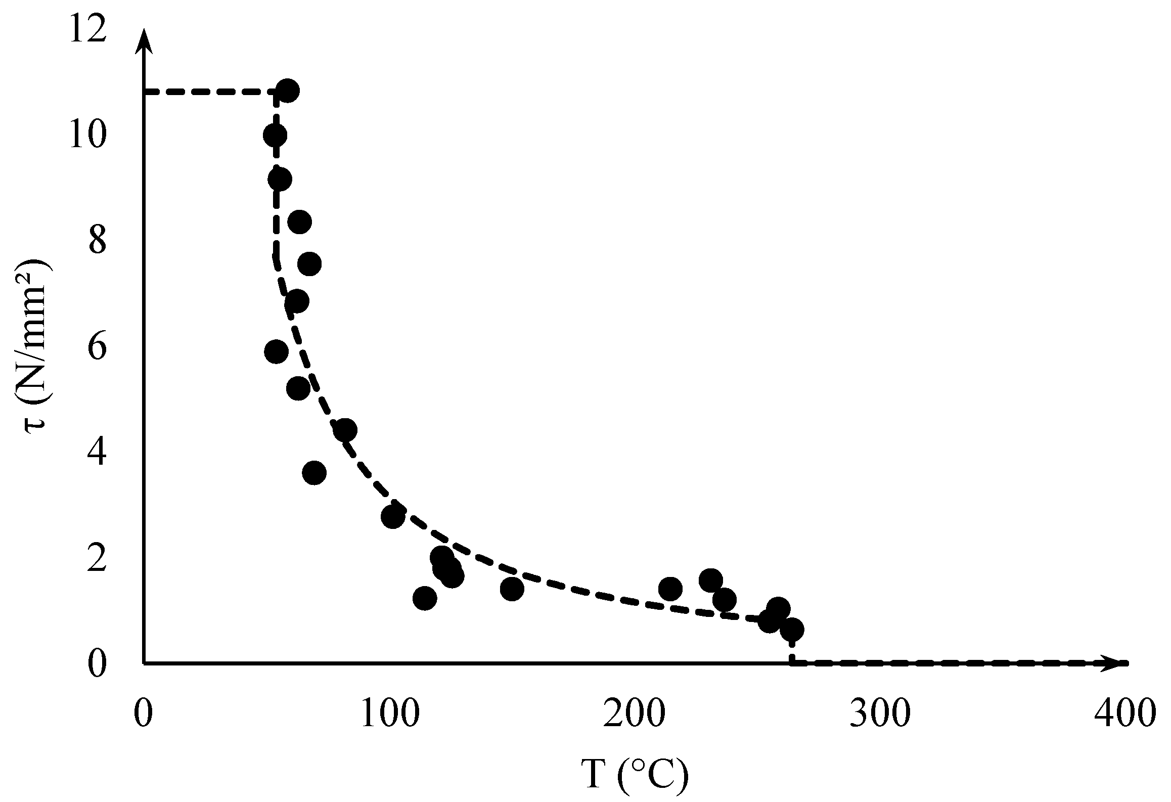
2.4. Bond Stress Capacity versus Temperature Relationship
The bond stress capacity vs. temperature relationship was obtained from tests according to EAD 330087-00-0601 [
15].
Figure 8,
Figure 9 and
Figure 10 show test results for the three adhesives used in this study. It should be noted that the evaluations of Adhesive-1 and Adhesive-3 have a large gap between test 150 and 200–250 °C. This gap does not respect the maximum distance between neighboring points given in the guidelines of EAD 330087 (50 °C). However, the other criteria for maximum distance of 1 N/mm
2 is respected. The curves were, therefore, considered beyond this gap for better representability of the adhesive’s behavior at high temperature. Placing an additional data point would fill the gap and have a negligible statistical weight on the fitting curve.
Furthermore, the criterion for maximum bond stress corresponding to 10 N/mm
2 for C20/25 concrete was not adopted in this study. The 10 N/mm
2 criterion is set by EAD 330087 for the design of PIRs, where a post-installed rebar is designed for the ultimate bond stress of a cast-in bar at ambient temperature. Bonded anchors are not governed by this criterion and the limit should be set, therefore, for their ultimate bond strength at ambient temperature. In this study, the upper limit of the bond stress vs. temperature curves was set to the reference tests at 20 °C for Adhesives 1 and 3, and the highest bond strength obtained at the beginning of the curve for Adhesive 2, due to the lack of reference tests (
Figure 8,
Figure 9 and
Figure 10).
3. Validation of Pinoteau’s Resistance Integration Method (RIM) for Fire Design of Bonded Anchors
The following validation has been presented partially in a previous publication by Al-Mansouri et al. [
28]. This paper provides an extended database for the validation of the resistance integration method thanks to the tests conducted at TU Kaiserslautern [
20].
To investigate the validity of Pinoteau’s RIM, pull-out fire tests were selected from two projects (
Table 1).
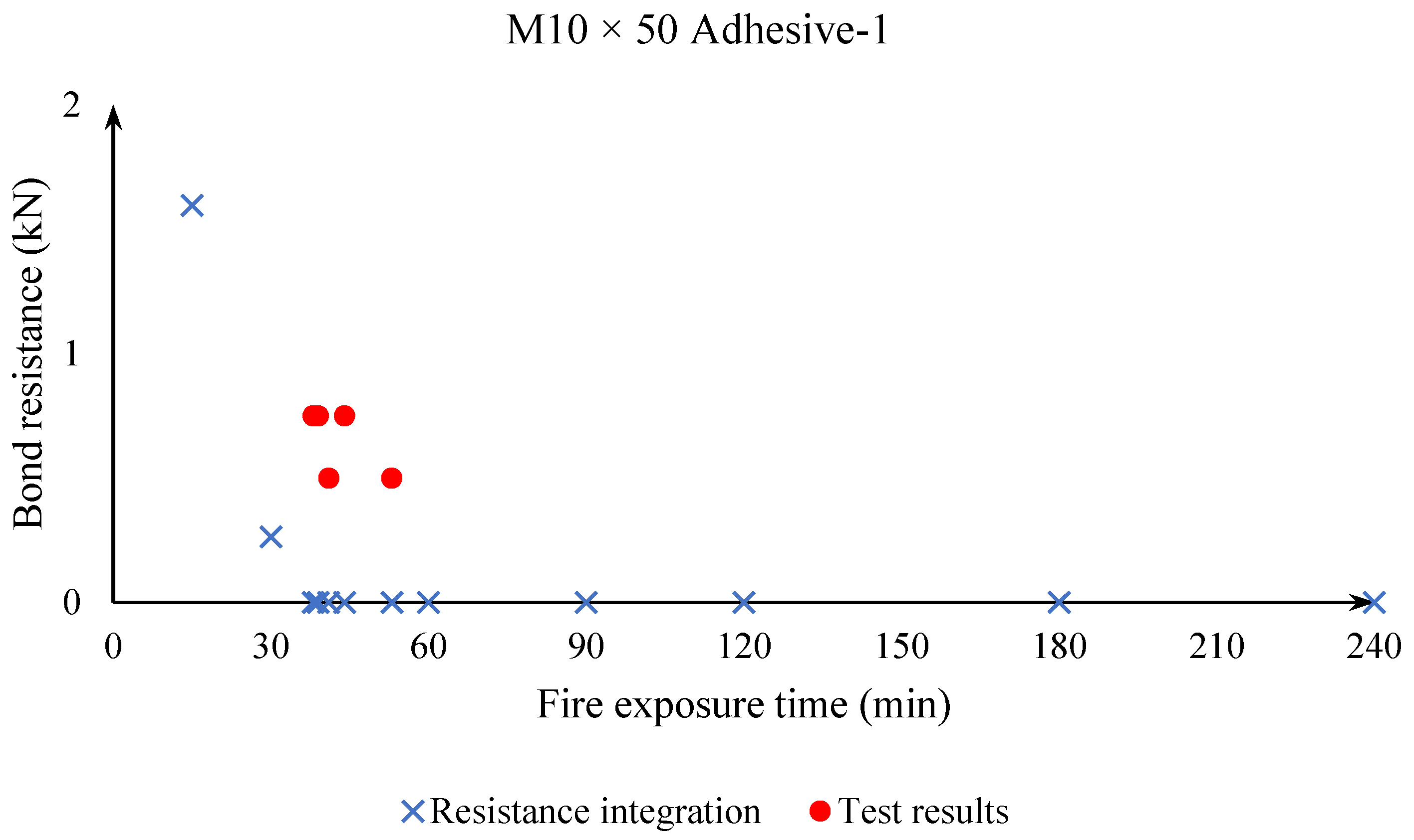
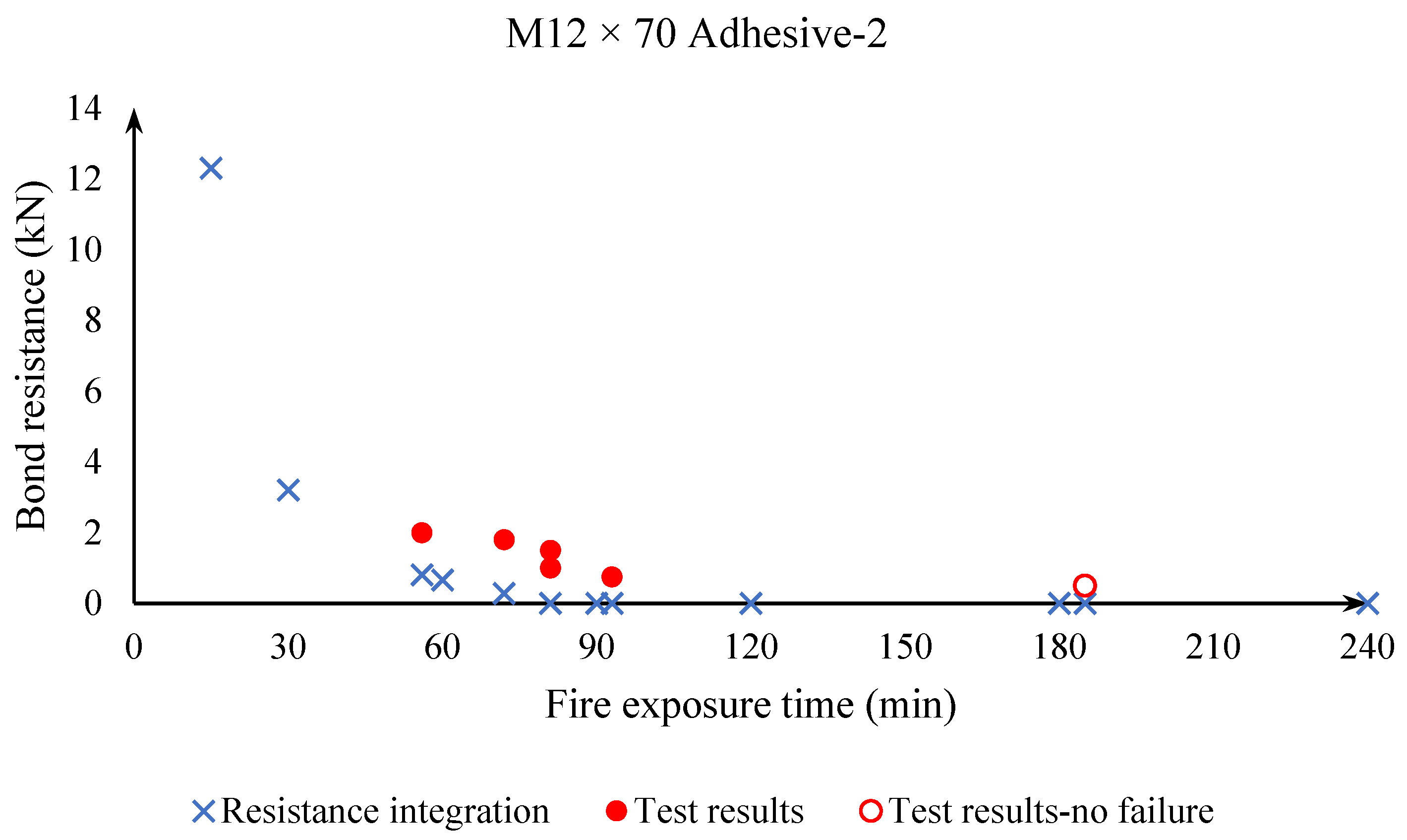
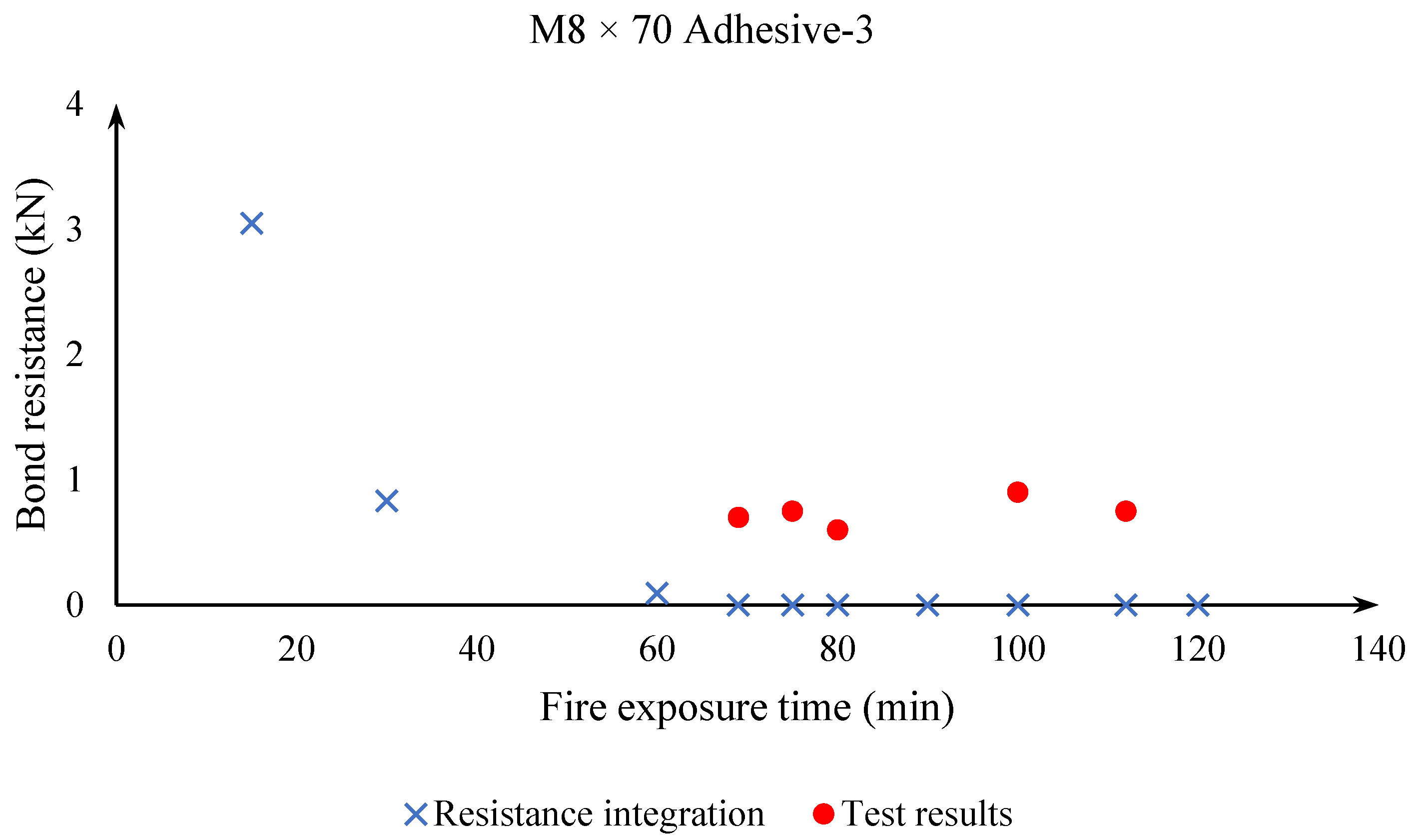
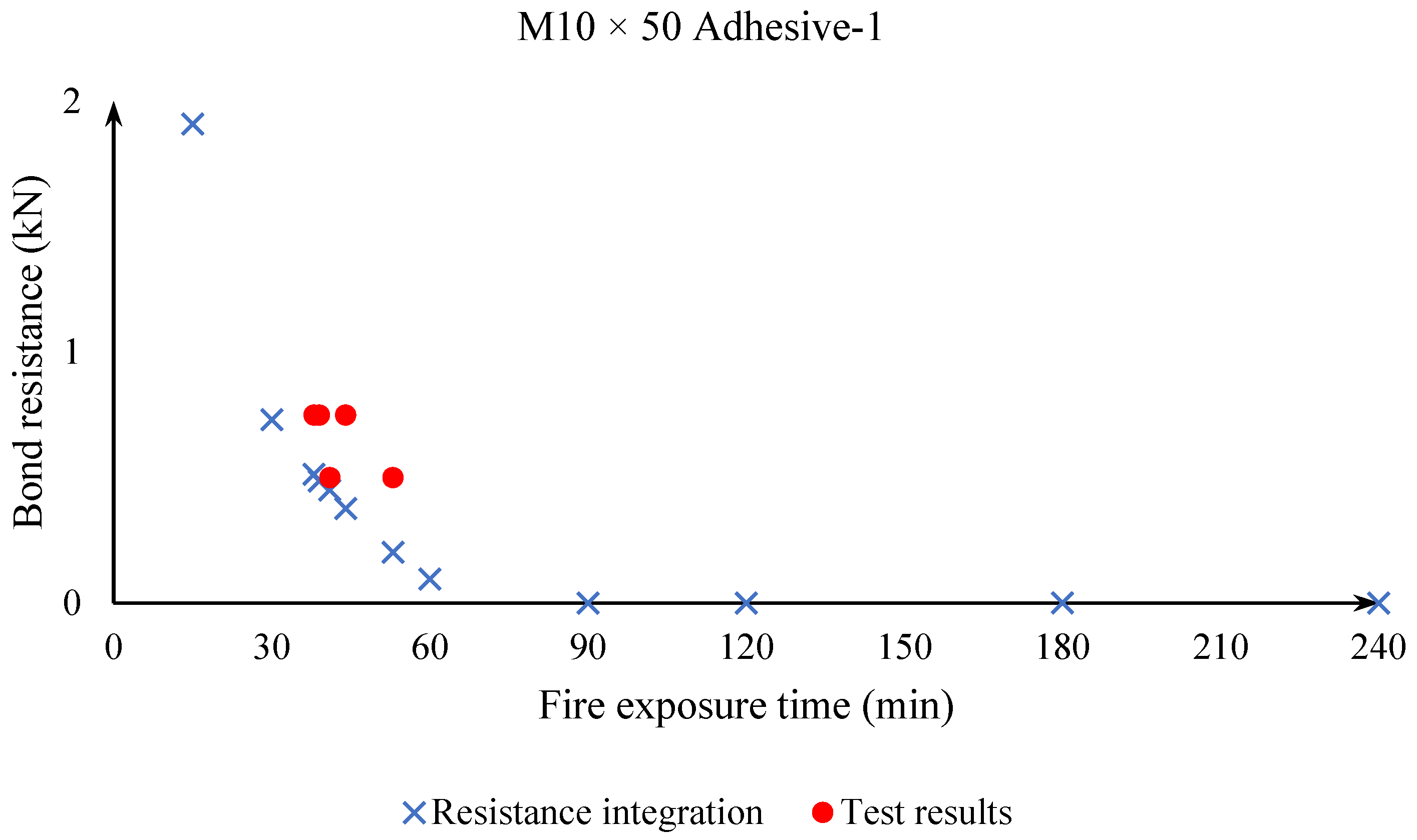
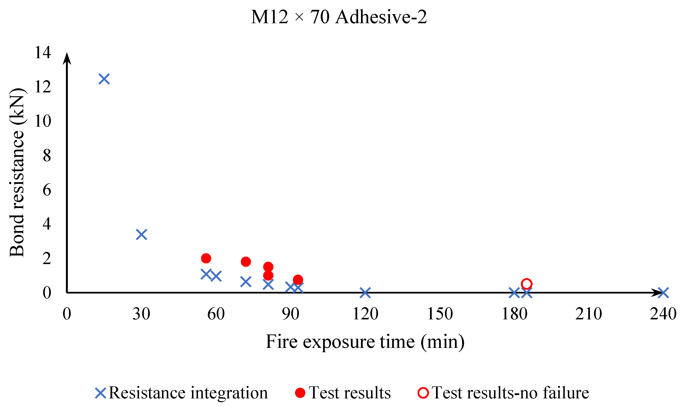
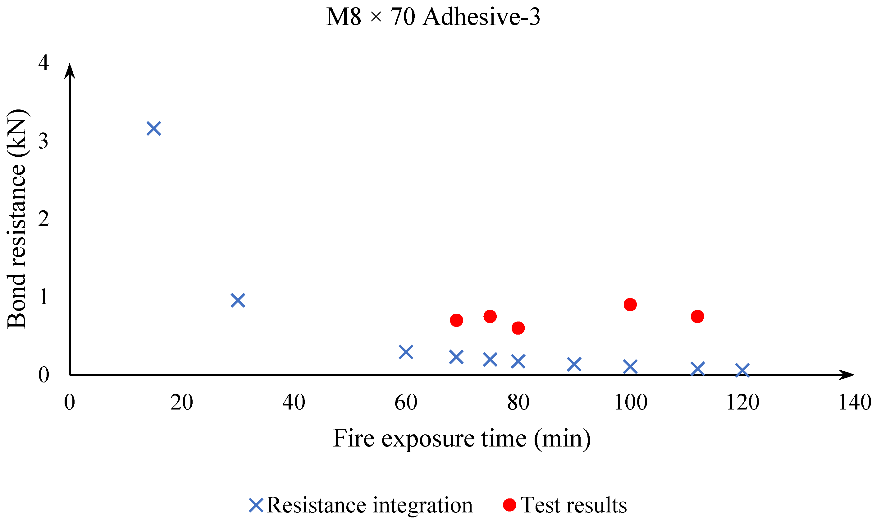
Figure 11,
Figure 12 and
Figure 13 show a comparison between fire tests and the outcome of Pinoteau’s method for one example of each of the three adhesives used in this study. The figures show calculated resistances using Pinoteau’s method (resistance integration) at 15, 30, 60, 90, 120, 180 and 240 min of ISO 834-1 fire exposure in addition to the times where pull-out failure in fire tests occurred.
Table 1 summarizes the data of this study: fire test data (applied load and pull-out failure time under fire conditions), Pinoteau’s RIM results considering the bond stress vs. temperature curve with/without considering temperatures beyond
.
From the previous results it can be concluded that Pinoteau’s method (resistance integration) can be used for the design of bonded anchors under fire conditions. Pinoteau’s method yields conservative design values compared to fire tests. However, some calculated resistances are too conservative where the design method shows that the anchor possesses no resistance under fire conditions. This is due to the fact that resistance integration is based on the bond stress vs. temperature curve. So far, this curve was only assessed through the approach in EAD 330087 up to a maximum temperature
for a maximum test duration of less than 3 h, beyond which no extrapolation is allowed. Therefore, in the resistance integration process, when the temperature of the anchor (in a segment or over the whole embedment depth) exceeds the maximum temperature of the bond stress vs. temperature curve, the segment is attributed zero bond stress, hence no contribution to the fire resistance. It should be noted that for an anchor exposed directly to fire conditions, temperature profiles reach and exceed the maximum tested temperatures in
Figure 8,
Figure 9 and
Figure 10 (usually chosen for fire evaluation of Post-Installed Rebars) along the embedment depth very rapidly. This explains the difference between calculated resistances and fire test results, where in reality the anchor still shows a certain resistance at these high temperatures (mostly by friction).
In order to minimize the difference between calculated resistances (Pinoteau’s RIM) and fire test results, a parametric study was conducted to assess the influence of considering the remaining bond stress beyond in the resistance integration method. This study is only informative and is only based on test data points up to around 300 °C. The curve is extrapolated beyond . For design of anchors in reality, this extension of the bond stress vs. temperature curve should be based on test data and not extrapolation. A study was conducted to assess the effects of extending the bond stress vs. temperature curve up to 450 °C on the design values of the studied adhesives.
Figure 14,
Figure 15 and
Figure 16 show an example for each of the three adhesives on the beneficial influence of considering the bond stress beyond
in the design method, on the calculated design values (fire resistance of the anchor).
It should be noted that Pinoteau’s RIM does not count as a predictive method for the fire resistance of bonded anchors. It contains several safety factors:
The method is based on evaluation of PIRs according to [
15]. The resulting bond stress vs. temperature curve is slightly conservative compared to tests on bonded anchors (threaded rod inserts). Adopting a curve based on tests with rods could have a beneficial impact on the calculated design values while still preserving the inherent conservatism of the method.
The bond stress vs. temperature curve is obtained for a constant load and increased temperature applied on the anchor until failure. Failure temperature is obtained by the weighted average of measurements of two thermocouples (head and bottom of the anchor) = 1/3 of the higher measured temperature and 2/3 of the lower measured temperature, yielding a conservative failure temperature value.
The stress (resistance) profiles are obtained based on temperature profiles calculated according to Eurocode thermophysical properties of concrete and steel using numerical modelling. These material properties are design properties. Calculation based on these properties yield conservative design values and not physically representative values.
The results in
Table 1 show that there is a beneficial effect of accounting for the remaining bond stress at high temperature in the design calculations. This benefit remains, nonetheless, on the conservative side as the design values do not exceed test results. Several factors could bring the design calculations closer to test results (reality). In this work, as a continuity of what the authors initiated in previous publications, the work focuses on minimizing the differences between reality and calculations (i.e., more realistic thermal calculations, better bond stress temperature curve to be used as entry data). The discrepancy between design and test results can be linked to a number of factors; of which the following can be noted:
The applied ISO 834-1 curve inside the furnace (allowing a certain tolerance of ±100 °C during the test). The allowance of such tolerance has an impact on temperature profiles. In addition, there are other factors at play, the objective of the authors was to remain on the conservative side.
The applied load on anchors (using dead loads or hydraulic jacks): using dead loads has proven to be more accurate since using hydraulic jacks has shown that it is hard to compensate the loss in applied load due to creep during the test (sometimes occurring very rapidly).
The population of the bond stress temperature curve obtained from EAD as entry data on PIRs, and its representability of the curve obtained using rods (curve based on rods was shown to have a similar or better behavior than the curve on PIRs).
The lower limit chosen for the bond stress temperature curve (maximum tested temperature proposed to be increased to at least 450 °C in this paper): a residual resistance can still be found above this temperature showing discrepancies for long exposures to fire conditions (i.e., high temperatures along the embedment depth) unaccounted for in the calculation method but demonstrated by fire tests.
4. Conclusions
This paper presents validation and parametric study of Pinoteau’s resistance integration method (RIM) for calculating the load-bearing capacity of bonded anchors in uncracked concrete under ISO 834-1 fire conditions [
17]. The method employs 3D transient heat transfer equations to obtain temperature profiles along the embedment depth of anchors. The temperature profiles then serve as input for the RIM, in which bond strength contributions of discrete segments along the embedment depth of anchors is computed during fire exposure. In this study, the method was validated with experimental results obtained in two previous experimental studies [
22,
23] on three different adhesives (two epoxy-based mortars and one cementitious based mortar) resulting in conservative calculations of load-bearing capacities at various fire exposure times compared to experimental results for various configurations and sizes of bonded anchors (sizes from M8 to M30, embedment depths from 50 to 120 mm).
A study was also presented after experimental validation of Pinoteau’s method. This study investigated the influence of considering the bond stress vs. temperature curve beyond the maximum temperature allowed for the assessment of post-installed reinforcement (PIR) in EAD 330087, resulting in the following conclusion: extending the curve up to a temperature of 450 °C yielded more advantageous and conservative design values (less conservative than stopping the curve at ~300 °C) for bonded anchors under fire conditions for the investigated adhesives.
The authors, therefore, recommend adoption of Pinoteau’s resistance integration method in assessment and qualification documents for bonded anchors under fire conditions. Furthermore, the extension of the bond stress vs. temperature curve by means of testing to benefit from the residual bond stress of the bonded anchor at very high temperatures is recommended. Since bonded anchors are directly exposed to fire through the steel element, they reach much higher temperatures in a short period of fire exposure time compared to post-installed reinforcement. The extension of the curve can be achieved by increasing the heat rate imposed on the characterization tests according to existing EAD 330087 procedures while respecting the 3 h and 5 °C/min heating rate conditions. Another method to achieve this goal can also be by conducting bond strength at increased temperature tests according to EAD 330087 procedures using stabilized temperature and increased displacement at the desired moment of characterization [
15].


 ,
, 


