
Towards a Flexible Smart Factory with a Dynamic Resource Orchestration
by
 , , , and
Milan Pisarić
1,* ,
,
Vladimir Dimitrieski
2,
Marko Vještica
2,
Goran Krajoski
1 and
Mirna Kapetina
2 1
Industrial Automation, KEBA AG, 4040 Linz, Austria
2
Faculty of Technical Sciences, University of Novi Sad, 21000 Novi Sad, Serbia
*
Author to whom correspondence should be addressed.
Appl. Sci. 2021, 11(17), 7956; https://0-doi-org.brum.beds.ac.uk/10.3390/app11177956
Submission received: 28 July 2021
/
Revised: 24 August 2021
/
Accepted: 26 August 2021
/
Published: 28 August 2021
(This article belongs to the Special Issue Information and Communications Technology for Industry 4.0)
Abstract
:Amid the current industrial revolution, a total disruption of the existing production lines may seem to be the easiest approach, as the potential possibilities seem limitless when starting from the ground up. On the business side, an adaptation of existing production lines is always a preferred option. In support of adaptation as opposed to disruption, this paper presents a new approach of using production process orchestration in a smart factory, discussed in an industrial case-study example. A proposed smart factory has the Orchestrator component in its core, responsible for complete semantical orchestration of production processes on one hand, and various factory resources on the other hand, in order to produce the desired product. The Orchestrator is a complex, modular, highly scalable, and pluggable software product responsible for automatised planning, scheduling, and execution of the complete production process. According to their offered capabilities, non-smart and smart resources—machines, robots, humans—are simultaneously and dynamically assigned to execute their dedicated production steps.
1. Introduction
Originating in Germany as Industry 4.0 (I4.0), the claim that society is amidst the fourth industrial revolution has been accepted and widely developed in the past decade [1,2]. Several governmental programs and paradigm-shifting initiatives that support and promote the idea are growing worldwide, with the most elaborated industries being in front—from ‘Smart manufacturing’ in the United States and ‘Made Smarter’ in the UK, to ‘Made in China 2025’ [2,3]. The scientific research community, although it sometimes struggles with the multi-disciplinary nature and wide perspectives of I4.0, has also given an impetus to great change [4,5]. In the I4.0 era, manufacturers are not only required to invest in technological infrastructure but also need to reconsider their existing business models and resources—including humans—to adapt quickly to changes in perspective [6]. Continuous adjustment to a human workforce is particularly important in Europe, where jobs involving manual work still constitute the second-largest category within the manufacturing sector [7]. I4.0 is faced with the challenge of blurred boundaries between the physical, digital, and biological worlds integrating new digital technologies into production processes. In addition, there is strong customer demand for highly customised products that are: with prices near to mass production, of increased quality, and need a short time to be delivered. Therefore, all manufacturers—in particular, Small and Medium-Sized Enterprises (SME)—need to adapt quickly to new trends and answer to the ever-growing list of requirements if they are to endure this revolution [8,9].
Smart Factory (SF) is nowadays a common term encapsulating the vision for factories of the future. The creation of a Smart Factory is one of the most frequent directions taken when applying I4.0, for both the scientific community and manufacturers [9]. Although many envision smart factories to be built from the ground up, thus having the total disruption, existing factories can be made ‘smarter’ by adapting them with the current technology. The introduction of the idea of enriching the existing device with a cyber component has gradually led to the wide acceptance of the Cyber-Physical Systems (CPS) as one of the key enabling technologies of SF and I4.0 [4,5]. A legacy device can be enriched with cyber interfaces and transformed into CPS in what could be considered retrofitting. Therefore, by using the know-how already gained in the past two decades, it is possible to partially retrofit, and thus adapt, the existing production systems into a flexible manufacturing system of the next generation. Such manufacturing systems are self-organised networks of machines, products, humans, and conveyors—the so-called cyber-physical production system (CPPS). By retrofitting legacy equipment and information systems, it will not matter what type the production participant is, as long as it can communicate with the complete CPPS. Additionally, the I4.0 movement is not gravitating towards workerless production facilities, unlike the CIM approach popular at the end of the last century. It is rather motivated to integrate people into this cyber-physical structure to maximise their potential [10]. Therefore, it will be essential to enable safe and fluent cooperation of human workers with other—smart and legacy—resources [6]. Recent advances in production research forecast that future production and manufacturing systems will integrate heterogeneous, decentralised, smart resources, and processes across all organisational levels of control [11]. All factories must gradually become ‘smart’ if they are to facilitate numerous cyber-physical systems communicating and cooperating synchronically with each other and with humans [3,9].
The communication and cooperation between all the participants in an SF will need to be well orchestrated, from early conceptualisation to late execution of the production. The production systems will reconfigure as frequent as new bespoke products are ordered. Currently, Product Management oversees checking that these orders are analysed and adapted by several groups of dedicated technologists and specialists. Their task is to plan, facilitate and reconfigure all the manufacturing tasks and resources [11]. These tasks are later scheduled and executed in an automatised production if all the required machines are available. If the shop floor includes human workers, they will simply follow and execute instructions provided to them. Robots and other machines are of course stopped, physically reconfigured and reprogrammed, and then finally ready for a new set of instructions. All these challenges are just the tip of the iceberg since there is also the coordination of the complete supply chain management, quality assurance, and production management. Ideally, the orchestration of all the above-mentioned processes is to be handled simultaneously, as a part of a synchronised computer system capable of coordination of preparing, scheduling, executing, and delivering a customised product.
Although the concept of production orchestration is already known, numerous questions require further investigation and answering before the wider acceptance and application of an orchestration solution. In order to guide this research work, our focus is on two research questions (RQ):
- RQ1: Is it possible to make formal models of production processes and shop floor resources aimed to enable and support dynamic resource orchestration?
- RQ2: Is it possible to create a system that would enable the automation of model-driven dynamic orchestration of shop floor resources?
The contribution of this research is reflected in the fact that the existing orchestration concepts have been reused and upgraded to provide answers to the above-stated research questions. Based on a model-driven approach and Domain-Specific Modelling Languages (DSMLs), the first aim of our research is to establish a foundation for formal modelling of any production process or any type of resource, thus addressing the RQ1. In addition to the production processes modelling already discussed in our previous papers [12,13], the foundations for formal modelling of resources are also presented here. The vision of Smart Factories based on our model-driven approach requires the existence of the Orchestrator as its core component. Therefore, the second aim of our research is to design a system capable of performing a model-driven dynamic orchestration, thus addressing the RQ2. Such an Orchestrator enables an SF managed and operated on a formal and abstract level by the experts within the factory. At the same time, the end-users perceive it as a self-contained black-box that delivers the desired product. In this paper, we present and discuss the architecture and application of this component. An additional contribution of this research is reflected in the design of a software architecture of the Orchestrator that industrial manufacturers and practitioners could implement when switching from traditional to advanced manufacturing systems in the emerging I4.0 era matching the current industrial setting. To the best of our knowledge, there is no solution published that covers every aspect of an SF addressed in this paper. As assembly processes have the tradition of pioneering the adoption of new technologies, it is not a surprise that Assembly 4.0 (A4.0) systems are expected to pioneer the integration of I4.0 technologies as well [14]. To discover the limits or to confirm the applicability of the Orchestrator, an industrial assembly use-case is used as a proof-of-concept. For the purposes of this research, an isolated and experimental assembly line has been set up following the proposed architecture. In this paper, we present the use-case and discuss the results.
The remainder of this paper is organised as follows: Section 2 briefly introduces the methodology applied in the research. In Section 3, the Orchestrator Architecture and its key elements are elaborated. In Section 4, an industrial case-study is presented as a proof-of-concept. Section 5 provides background literature research, in the context of the presented architecture. The paper is concluded in Section 6, with a summary, discussion about the Orchestrator application in an industrial case-study, and insight into the future activities of the research group.
2. Methods
Based on the knowledge and preferences shared by the stakeholders of an EU-based manufacturer, and a literature review of state-of-the-art I4.0 smart factories, we were able to define the initial steps for designing an SF capable of answering research questions. To restructure and expand the existing know-how in dynamic orchestration, the principle of Design Science Research (DSR) was used. As it is fundamentally a problem-solving paradigm, DSR ‘seeks to enhance existing human knowledge with the creation of innovative artefacts and the generation of design knowledge via innovative solutions to real-world problems’ [15]. Therefore, the DSR methodology is considered to be a well-suited methodology for exploring the practical usefulness of generically designed technological artefacts to answer the research questions within the field of information systems [16,17]. The DSR methodology process model presented in Figure 1—originally elaborated in [16]—is chosen and adapted according to the purposes of this research. This DSR process includes six research steps, enumerated in Figure 1: (I) Problem Identification and Motivation, (II) Definition of Solution Objectives, (III) Design and Development, (IV) Demonstration, (V) Evaluation and (VI) Communication. These six steps are iterated as shown in Figure 1.
The kick-off of this research was the investigation carried out with the goal of increasing the automatization and flexibility of the contemporary production lines, under the I4.0 trends. At this point, we formed a team, as a part of the first step of the research process. The second step started with our intention to identify and define the main research problem behind the above-mentioned goal. The stakeholders and industrial practitioners presented to us the contents of their internal analysis of work previously published by industrial competitors. These internal analysis results were written in a form of whitepapers, thus representing the initial output of Step II of the research. In addition to that, we have analysed the state of the art in scientific literature and discussed it as the second output of Step II. This analysis is presented in Section 5 of this paper. Knowledge gained in Step I and Step II lead to the problem specification and the definition of the first objective; to improve the existing artefacts found fitting to solve the main problem. As a part of the third research step, the architecture of the Orchestrator software solution was designed and is presented in Section 3 of the paper. For the fourth research step, we found adequate use-cases that could be used as demonstrators of the usability of the designed architecture, an artefact of Step III. The best-fitting use-cases would be those that involve experimentation, simulation, case-study or proof-of-concept [15]. The Demonstration is covered in Section 4 of the paper, where an industrial case-study is discussed.
Although all the above-described iterative steps were covered, they are denoted differently in Figure 1. The steps denoted with the pattern-filled rectangles (steps III and IV, and partially steps II and VI) are presented in this paper. The Evaluation (V) is currently under way and only initial results are briefly discussed here. Additionally, this paper is considered as the first output of the Communication (VI) phase. An extensive discussion of the Evaluation step will be a topic of further research and communicated in future publications.
3. The Orchestrator
The Orchestrator is a complex, distributed system designed to support and enhance the flexibility of both new production systems—made from the ground up—and old ones adapted to be smart. It orchestrates a safe collaboration of all types of factory resources—humans, machines, robots—with the aim of successfully bringing the production to end result.
Formally specified production processes are fed to the Orchestrator, which is in turn responsible for the complete orchestration—modelling, matching, scheduling, and enriching the process—and for the execution of final production steps in an SF’s Digital Twin. The Digital Twin (DT) metaphor is a part of the I4.0 movement which implies the mirroring of a real system, to include both the physical appearance and its behaviour [18]. Although different in nature, once formally modelled as DTs within the Orchestrator, all the resources are used uniformly, not depending on their type. Execution commands, received from the Orchestrator, are propagated by a DT to its correlative resource to be carried out at a shop floor level. The notion of production orchestration represents mixed activities of scheduling, both batch product planning and operation scheduling, and allocation of operation steps on resources. These activities are to be performed automatically, enabling the fast and dynamical adaptation of the shop floor to the customers’ needs. This paper is a continuation of the segments of our research previously presented in [13,19].
The distant goal in applying the Orchestrator is to reach the milestone of ‘the assembly of anything’ in SF which will implement listed principles:
- Complete production flow is coordinated by the Orchestrator, from ordering to delivering an assembled product.
- Assembly tasks are dynamically distributed among various resources.
- All resources have a uniform treatment, including a human worker as a potentially central figure.
- Retrofitting of legacy resources and Plug-and-Produce is supported, to first adapt the current production into an intermediate, smarter factory solution, ‘SF3.5′, before reaching the long-term goal of ‘SF4.0′.
- Generic and powerful process and shop floor modelling tools that would enable easy customisation and adaptation of the previously gained modelling knowledge.
- Simulation is synchronised with the real-time execution, thus enabling powerful monitoring and quality control.
- All resources collaborate safely in real-time.
- Standardisation and interoperability are strongly advocated but not a limiting factor.
All the mentioned principles can be applied more abstractly to support future production as a whole—i.e., manufacturing, supply chain, packaging, and delivery—and are not limited to only one domain. A vision of an SF in which these principles are applied is enabled by introducing the architecture of the Orchestrator presented next.
Architecture of the Orchestrator
The Architecture of the Orchestrator described in this Section is a resulting artefact of Step III of the DSR methodology described in Section 2. Architectural elements of the Orchestrator are presented in Figure 2. Differentiated here are the internal, core infrastructure components—enclosed within the dashed-line rectangle—and external components, that are more oriented towards users of the Orchestrator. Users of the system are not only the end-customers but also plant managers, process engineers and quality engineers, among others. The plant manager specifies the factory’s shop floor model and oversees the production, while process and quality engineers specify process models.
On one side, the Orchestrator can be seen as a self-contained black-box. For end-customers, the output of the black-box is the desired product, the specification of which is given as an input to the system, while the entire production system is self-orchestrated in the background. On the other side, several elements of the Orchestrator are pluggable, to provide process and quality engineers with the possibility of adapting the solution to various use-case or even factory-specific requirements, e.g., the user interface. The plus symbols in Figure 2 denote these pluggable elements. The full red line depicts the orchestration ‘Happy flow’ (i.e., ‘Happy path’), which is a default orchestration scenario that follows the numbered elements. The outset is the user interface (number 1) and the closure is the execution of production using available Resources (number 9) without experiencing any error states or unexpected behaviour. Other elements, although not numbered, contribute to the integrity and completeness of the solution. Description of other orchestration scenarios goes beyond the scope of this paper. The overall architecture of the presented system is modular and is implemented as a set of software components packaged within Docker containers. Every software component is a software agent. Each respective entity has some intelligence attached to the software components, enabling the realisation of a modular, smart, and pluggable software infrastructure. The high scalability of the system and running on cross-platform with minimum time to set up is allowed by introducing de-coupled containers. They are started, stopped, and run in multiple instances independently and can be seen as isolated and complete micro-services. These containers are run and instantiated on-demand, depending on a multitude of factors such as the load on the existing container instances or the number of concurrent requests.
The entry point of the system is the Customer Interface (1). It is structured in a way that supports the development of flexible ways to interact with the complete production facility. This is one of the components suitable for factory-specific or user-specific adjustments. Its pluggable fashion enables a customer to express an individually customised product in various input formats, depending on the particular use-case. These inputs are later converted into a more generic product model or even a standardised digital product-specification (such as Computer-Aided Manufacturing (CAM) or Computer-Aided Design (CAD) models). An individual customer-defined product specification is simultaneously an input for the Orchestration Agent (2) and an order for the Orchestrator system. The Orchestration Agent is a principal component in charge of all other processes inside the Orchestrator. An agent can be seen as a state machine that runs each user’s product order through various states—from matching to execution—to create the desired product. For each new order, a new Order Agent is instantiated and resides in the Orchestration Agent that stores the current state of the actor’s state machine. The state machine overviews all the steps that need to be executed for an order to become finalised, and asynchronously invokes other components depending on the current state of an individual actor.
The first component to be invoked by the Order Agent is the Process Reasoner (3a). It is provided with a product specification as the input, thus starting the reasoning phase. The main function of the Process Reasoner is to reason upon all required capabilities, steps, and order of the sequences in order to generate the process specification as an output. The process specification is a technology-agnostic and shop-floor-agnostic description, which does not include resource allocations. On the contrary, it should hold complete information about the bill of materials, quantities, timing constraints, acceptance, and completion criteria. Similar to the Customer Interface, the Process Reasoner is also one of the components implemented in a pluggable fashion so it can respond to the use-case specific requirements. Once inferred, the production process specification can be further customised using one of the supplied tools for modelling. The Modelling Tools (3b) component, as seen in Figure 2, represents two independent tools—Process Modeller and Resource Modeller—used by the Process Engineers and the Quality Engineers in the modelling phase. The main purpose of the Process Modeller is to allow alteration of the production process specification that is the product of the Process Reasoner [12]. Its utilisation allows a customer to alter the existing production processes’ specifications—either previously created or inferred by the Process Reasoner—or to create a production process specification from scratch. Since product specifications might be provided in forms that are not machine-readable, the ability to manually create and edit production process specifications is of utmost importance. This way, the customer interface is being enriched or practically substituted. An example of the Process Modeller usage applied to an industrial use-case is further described in Section 4.
The Knowledge Base (4) data provide the required domain production knowledge in a machine-readable form. It facilitates deductive reasoning, as it is based on well-defined and formal meta-models. KB also contains a comprehensive map of required connections in the system, both physical and logical connections among the resources. Based on these connections and the inputted processes, it provides the topology upon which an appropriate flow of operations can be created. This component is the enabler of storing the factory’s specific data, such as data about resources, their capabilities and constraints, collaboration models, interface contracts, and factory logistics. KB keeps the information of all the resources on the shop floor, including the spare (e.g., tools or machines that are not currently in use but are available) or temporary unavailable (e.g., operator on a vacation, or a machine on reparation) resources. As it also preserves the semantics of processes specifications, it plays a key role in orchestrating production. Furthermore, KB provides an inference and query mechanism that can dynamically find connections between available resources. In this way, the Orchestrator can find a semantic link and orchestrate the complete production in real-time.
The Resource Discovery is not considered a part of the ‘Happy flow’, as the KB is already populated with all available resources at the moment of the Orchestration Agent triggering. If that is not the case, this component enables the dynamic addition of resources that enter the shop floor. Smart resources report themselves upon entering the system and their specification is dynamically inserted into the KB. Ideally, every resource will have a standardised asset administration shell developed and available [20]. They will provide a semantic self-description of an asset and interaction contract specification of offered capabilities. That way, a resource will be recognizable at the entry to any system in a plug-and-produce fashion. Nevertheless, the customer is provided with an additional modelling tool aimed at the specification of smart resources. The Resource Modeller (part of the Modelling Tools component, 3b) serves the system similarly to the Process Modeller. It allows a customer to alter the existing resource model—that is otherwise automatically generated in a plug-and-produce fashion—or to create a new one from scratch. The latter is used in cases when legacy or non-smart resources have to be described and specified within KB. The Resource Modeller enables detailed description and specification of these resources and their connectivity interfaces relevant for the orchestration, from the ground up. All the resources, capabilities, and constraints are paired with their digital entities, and consequently form a detailed factory resources model that can be exported to, or imported from KB. Resource Modeller also provides the basis for formal modelling of all resources, not depending on their type. Consequently, it is an essential component for providing use-case-specific resource additions to the factory topology, and for subsequent uniform treatment of resources. An example of the Resource Modeller usage applied to an industrial use-case is further described in Section 4.
The process specification that is a result of the reasoning and modelling phase is used as an input for the Resource Matcher (5). The main function of this component is to carry out the multi-step matchmaking of the capabilities required by the production process and capabilities offered by the existing resources. On one side, there are required capabilities, constraints, acceptance, and completion criteria provided on the input. On the other side, there are available resources’ specifications stored in KB. Based on the resources’ offered capabilities, the Resources Matcher matches them to the processes and the required capabilities. The first step of this matching process results in a set of possible production processes with already allocated resources. These are structured as a set of directed graphs in which each graph represents an individual process—practically a variety of production process specifications. The matchmaking continues with the enrichment of the previously generated production processes. The production process variations are expanded in a sequence of enrichers. The resource level enrichment comprises the preparation of a product order, in which additional production steps are inferred based on the physical organisation of available resources and the factory topology. Based on the same topology, the logistic enrichment additionally adds logistic steps to complete the material flow among the resources during the production process. The result of this step, and an output of the Resource Matcher component, is another set of directed graphs, in which each graph now represents an enriched variation of a process specification.
The Production Scheduler (6) is one of the most complex components in the system, as it is inputted with a formed graph of all feasible process specifications matched with resources and offered capabilities, process steps, and material allocations. To deal with the complexity of scheduling, it is common and expected to apply certain restrictions and assumptions on several levels. Additionally, the datasets and objectives are large, so no optimal computation of the schedule could be calculated as it would require infinite time. Here, the Production Scheduler is based on a heuristic algorithm that leans on information already stored in KB. The algorithm takes into consideration assumptions and restrictions—i.e., regarding logistic steps, material allocation—which provides a (sub)optimal solution of process order. The infrastructure established here enables constant improvements of this component. It is possible to insert some use-case-specific algorithms and optimisation criteria for each domain in which the Orchestrator is applied. The Production Scheduler outputs a sequence of resources assigned with operations and timing constraints, ready to be executed on the shop floor.
The Communication Protocols (7) are a group of software components developed for each communication protocol, which oversees translating generic execution commands sent to a DT into instructions passed to the physical resources through an appropriate protocol. The Orchestrator automatically generates execution commands based on the semantic specification of resources in KB and generated production process specifications. The structure of execution commands inside the Orchestrator is common and shared among all resource types. However, every communication protocol acts as a resource proxy and is in charge of translating generic commands received from the Order Agent. The generic commands are translated into resource-specific commands that are to be executed, thus making this component the actual Orchestrator executor. Although the executor handles generic commands, different resources will communicate via various protocols and interfaces; the operator interacts via a human-machine interface (HMI) while machines communicate via standardised industrial interfaces. The Communication Protocols component of the Orchestrator is still very factory-specific and will continue to be so until a larger proportion of standardisation within I4.0 implementations is achieved. Together with the Communication Protocols, the Digital Twin (8) is an essential component in the chain of execution of the concrete production process steps. DT partially takes an executor role and oversees the final execution of commands. It is an interface between an individual Communication Protocol in the orchestration layer and a targeted resource in the physical layer of the system. The complete factory shop floor is faithfully mirrored in the DT, wherein each digital element reflects an actual resource that it is paired with and can communicate with. High-level information about resources is stored in KB and is used for matching. In addition to this, DT includes a dynamic store containing low-level data needed for the production scheduling and final steps of process execution. The last state stored in DT is a starting point used for scheduling. All this provides the possibility to utilise the DT as the simulation only, as well as to simultaneously execute the production process while visually presenting it. DT sends the appropriate command for each production process step. This command is then propagated to a targeted resource via a corresponding Communication Protocol.
Resources (9) are all the assets involved in the production. In the described system, various types of resources—humans, robots, software agents, and machines—are all treated uniformly and are only differentiated by their capabilities, interactions, and interface specifications. Together they constitute a shop floor, upon which the production itself is being orchestrated and the assigned tasks executed. All the resources are modelled in a corresponding resource model included within KB. A human worker, the O4.0, is modelled with its capabilities (i.e., inspect, analyse, turn) that are not necessarily different from robot capabilities (i.e., pick-and-place, drill, turn) but are differentiated by adequate constraints. Although robots and machines can operate with heavier loads or without fatigue, Operator 4.0 is considered to be the most flexible asset in SF [21]. Therefore, it is not strange that the biggest variety of capabilities and constraints are related to this resource type. Additionally, some competencies and man-machine interactions—e.g., operator and cobot collaboration—are unlikely going to be replaced by a single device, unless production is based entirely on Artificial Intelligence (AI).
The communication between the Orchestrator components is established through an internal communication layer based on a highly scalable communication backbone. Intra-component communication is implemented through a broker-based messaging system. An additional, distributed Logging Bus is being fed by every component, which provides detailed logging data and tracing. This component is essential for rule-based Error Handling. According to the information stored in logs, a corresponding error-handling mechanism is triggered. The triggered mechanism provides a predefined set of steps taken in every matching component, including matching and scheduling. The Dashboard and Analytics component represents a set of additional, pluggable tools of various kinds. They also lean heavily on the communication layer and are customised based on use-case-specific needs. The main function of this component is to provide a chance not only to the customer but also to additional factory users—i.e., Operators, Managers, Engineers. By using the data collected via the logging bus, these users can perform additional analytics of the orchestration or the final execution of the production process.
With the described architecture, we propose a vision of SF capable of maximising the currently available technologies, but also a system highly adaptable to existing production facilities. Here, we present the foundations for an infrastructure capable of scaling and allowing a large flow of information, with system components that are modular, independent, and scalable. This enables both vertical and horizontal scalability. Finally, a software system based on the proposed architecture is technology-agnostic, as it anticipates and supports implementation and running both on isolated industrial PCs and on large distributed systems or in a cloud.
4. An Assembly Use-Case
The application of the Orchestrator is discussed and evaluated on several use-cases, as a part of Step IV of the DSR methodology applied in the research. A first assembly use-case was used to set up a laboratory with accompanying simulation and is previously discussed in [19]. Additional use-case, described in this paper, represents a proof-of-concept through an industrial case-study carried out in an isolated and experimental assembly line of an EU-based manufacturer. One of the product types from their product range is shown in Figure 3. It is an industry-optimised controller with built-in I/O elements, that consists of a mainboard with all electronic components pre-integrated, and a compact casing. There are several product variants, slightly differentiated by the interfaces on the front side of the controller. For this paper, it will further be addressed as Controller-A.
This case study is based on a simplified real-world assembly process consisting of the following steps:
- The integrated mainboard is placed in the plastic bottom casing.
- Optionally, the default interfaces are replaced with customer-specific ones.
- The front casing is placed above the mainboard and sealed.
- The testing phase is conducted by two collaborative resources working in parallel:
- one is holding the product and performing a robust test, and
- the other is visually inspecting the product.
- If any defects are found in the inspection phase, the product is sent for reassembly.
- If no defects are found, the product is sent for packaging. Both reassembly and packaging are considered separate, complex sub-processes.
The complete orchestration process of the assumed Controller-A assembly is described below, elaborating the impact on all the elements of the architecture depicted in Figure 2. Complex sub-processes (assembly process steps 2 and 6) are not described in-depth, as they are decomposed into simpler steps similar to those described below. The numbers given next to all the architectural elements are the same as in Figure 2.
Usually, in the first step of the orchestration process, a client uses the customer interface (1) to specify a product. The client creates a specification of the product and uploads it, upon which the Orchestration Agent (2) triggers the Process Reasoner (3a) to generate the production process specification and store it in the Knowledge Base (4). This is not the case in the concrete example, as the interface for the upload of the predefined input format is not developed. Process or Quality Engineers will instead use a provided Process Modeller tool (3b) to create the desired production process from scratch and import it to the KB. Therefore, the specification of the production process, similarly a recipe that is used for complete orchestration of all the resources towards the product being delivered, is either created or extended within the Process Modeller.
Figure 4 depicts an example of a production process model of the assembling of Controller-A. The model example is created by using Multi-Level Production Process Modelling Language (MultiProLan) that is developed for production processes modelling, models of which are suitable for automatic generation of instructions [12].
The first process step after the process starts is ‘Put Mainboard into the Case’, represented by a sharp-edged rectangle with an inscribed circle. To perform this step, an allocated resource will require the ability to perform assembling operations and to meet certain constraints while acting. Therefore, this process step is linked to the capability ‘Assemble’, depicted by a rounded rectangle. It is also required to determine the inputs and outputs of every process step, and for this step, the inputs are a bottom cover and a mainboard, while the output is the mainboard placed into the cover. Both inputs and outputs are depicted in Figure 4 by a rounded rectangle marked with ‘OUT’ or ‘IN’ in its heading, linked to the process step. The next in line is ‘Customise Interface Layout’, which is a sub-process consisting of several simpler process steps and is depicted by a rectangle with a dashed borderline. It is an optional step and will be performed when required by the product specification. The optionality of this execution is implicit and encapsulated within the element.
The output of the previous process step is an input for the next one in the process flow, as seen in Figure 4, represented by a directed dashed line between the output element of ‘Put Mainboard into the Case’ and the input element of ‘Customise Interface Layout’. These output-input dependencies are depicted in the same fashion for the other process steps and sub-processes. The next process step is ‘Put a case cover’, which also requires the capability ‘Assemble’, with an uncovered controller on input, and covered controller on output. All used symbols are the same as already described and will not be repeated. The next three process steps—‘Inspect Device’, ‘Robust Tests’, ‘Hold Device’—are to be performed simultaneously. The first two are directly dependant on, and cannot be executed without, the successful execution of the third one, as ‘Hold Device’ is started before and ends after the finalisation of the other two. This is depicted by two directed, dot-dashed lines marked with ‘Start’ and ‘End’, respectively. In the given example, ‘Hold Device’ marks the start, while ‘Inspect Device’ and ‘Robust Tests’ together mark the end for all three process steps. These three process steps are to be performed in collaboration with at least two allocated resources, as product inspection and product testing are carried out by separate resources, while one of the two can also hold the product being tested. This three-way execution of production is depicted with directed lines leading from and into rhombus noted with ‘COL’. Listed production steps are also linked to corresponding capabilities (i.e., ‘Test’, ‘Inspect’, ‘Hold’), inputs and outputs—as previously described.
Next to be executed is the sub-process ‘Reassemble’. It is an optional step and its execution depends on the output of the previously performed ‘Inspect Device’ step. Unlike previously described in the case of ‘Customise Interface Layout’, the optionality is here explicit and is depicted by lines directed from and into the rhombus decision element noted with the ‘DEC’ mark. Finally, the last sub-process to be executed is ‘Packaging’. Input for the packaging is either a checked or a reassembled controller, and the output is a ready-to-deliver Controller-A. Both ‘Reassemble’ and ‘Packaging’ encapsulate a more complex structure consisting of the previously described elements. As seen in Figure 4, colours are also used for semantic enrichment of the diagrams, i.e., Process step rectangles are green; Inputs and Outputs are of various shades of blue. This is only a brief description of the Process Modeller and the MultiProLan modelling language used here, as they are the focus of previously published papers [12,13].
After the input of a modelled production process, the order is placed and the Orchestration Agent (2) initiates the Orchestrator mechanisms upon which the desired product is being processed. The Process Reasoner (3a) uses the necessary information and data specification of the previously generated production process to deduce all the production steps according to the factory-specific topology and the use-case. The semantic information stored in KB (4) is used by the Resource Matcher (5) to match the existing Resources (9) and their offered capabilities and capability related constraints, with the capabilities requested by the production process specification and previously deduced production steps. Any desired product is to be assembled out of parts available on the shop floor, using the resources specified in the KB and without any additional programming. At the initialisation of the shop floor, the KB will be automatically populated by triggering the Resource Discovery mechanism. Smart resources will introduce themselves and offer their capabilities to the Orchestrator. The Resource Modeller tool serves as a backup or the additional way to add other, non-smart, or legacy resources, and it is used by engineers to create a factory-specific topology.
Similarly to the described utilisation of Process Modeller, for this use-case, the Resource Modeller was used to model the available resources (listed in Table 1) from scratch and then to import this to the KB where the model is stored. Figure 5 depicts an example of the resource model created for the assembly of Controller-A. As visual representations of these models can easily be overcrowded with symbols, layering mechanisms are utilised to enable the showing and hiding of different model aspects. Resources, capabilities and constraints are presented in the default layer of the resource model. ‘Operator1’ and ‘Operator2’ are the two available human workers, augmented by smart mobile devices used for communication with the Orchestrator. All resource types—rounded rectangles on the left and right side—have a graphical symbol of the resource-type inscribed in the header (i.e., a wired human hand for O4.0; 6-axis robot for Robots; packaging machine for Machines). Both operators are capable to assemble and inspect, and ‘Operator1’ is also capable to reassemble.
The relation between a Resource and a Capability is performed over a corresponding CapabilityRelation element, depicted by a rounded rectangle without a header. In the given example, individual CapabilityRelation elements link both operators to Capabilities ‘Inspect’ and ‘Assemble’, while ‘Operator1’ is additionally linked with ‘Reassemble’. Capability elements, rounded rectangles centred in the diagram, are also decorated with a corresponding capability-type symbol, i.e., human head for cognitive capability, a molecule-like symbol for physical capability. In the given example, ‘Inspect’ is a cognitive capability, and all the others are physical capabilities. In addition to the main function of linking resources and capabilities, CapabilityRelation also contains Constraint elements—each individualised for a concrete resource–capability combination. These are depicted by grey rectangles with inscribed textual descriptions and symbols that represent constraint type, i.e., a book for production process constraints, a hand and a dumbbell for physical constraints, scales symbol for legal constraints. In the given example, constraints for both ‘Assemble’ and ‘Reassemble’ are limiting ‘Operator1’ to load weight up to 1 kg and not more than 40 times per day, while capability ‘Inspect’ is specified as tool dependant.
All the other resources (listed in Table 1), their offered capabilities, constraints and interfaces are instantiated in a fashion similar to already described for ‘Operator1’. Colours are again used for semantic enrichment of the diagrams (i.e., Capabilities are orange; Resource elements are yellow). The topology layer, which specifies the shop floor topology and material flow of the model from Figure 5 is depicted in Figure 6. The directed dashed lines between resources represent the possible interactions among them, with the arrows denoting the direction of material flow. The in-depth description of the Resource Modeller is out of the scope of this paper.
In the next phase, the Resource Matcher (5) first produces a production process variation in which it assigns resources to their dedicated production steps for the assembly of Controller-A, i.e., ‘Operator2’ is matched to execute ‘Put mainboard into the case’ and ‘Put a case cover’; ‘Cobot’ and ‘Operator1’ are to execute the collaborated test and inspection; ‘Operator1’ is to perform the reassembly. The next phase carried out within the Resource Matcher component is the logistic enrichment, performed according to the information stored in KB; availability of the resources on the shop floor, the current topology of the resources (also seen in Figure 6), physical limitations of the collaboration between resources, etc. Upon this phase, material flow steps are deduced, which leads to the creation of additional production steps. In the concrete use-case, as seen in Figure 7, the inferred steps are ‘Pick Device’ and ‘Move to Inspection Bench’. Either ‘AGV1’ or ‘AGV2’ will be assigned to perform them, consequently carrying the necessary production parts and the assembled product between the resources carrying out the assembly, inspection and packaging. This results in Resource Matcher not only offering a match for every production step described in the generated or created production process but also providing an optimal match for all the inferred logistic steps.
The Production Scheduler (6), as soon as the matching process has been performed, is to find an optimal schedule by analysing the execution order of all the matched production steps. The execution time and the uniform resource utilisation were the two optimisation criteria used for this use-case, intending to assemble a controller as quickly as possible while equally using all available resources. A completely orchestrated production process, the result of the matching and scheduling phase, can be reviewed on a detailed level in the Process Modeller. Figure 7 depicts only an extract of the enriched production process model created for the assembling of Controller-A, as seen in Figure 4. ‘Cobot’ is assigned to execute ‘Hold Device’ and to simultaneously perform ‘Robust Tests’, while ‘Operator1’ is performing ‘Inspect Device’ in parallel. ‘AssemblyRobot’ will never be assigned to carry out the testing, although it is capable of it, as it cannot simultaneously hold the device targeted for testing. ‘Operator1’ and ‘Operator2’ are capable of performing the collaborated inspection, but ‘Operator1’ is a more experienced worker and will more likely be assigned for the testing unless he is already assigned for the ‘Reassemble’ sub-process—as ‘Operator2’ is not capable of performing it.
After the completion of the matching and scheduling phases, each command is propagated to the individually assigned resource via a dedicated Communication Protocol (7). Answering its main purpose, every Protocol translates the generic command into resource-specific commands for the execution. These proxies are leaning on the Digital Twin (8) component that is practically acting as an executor, by propagating factory-specific instructions to the designated resources. In the described use-case, commands for robots are sent via a bridge based on Robot Operating System (ROS) framework, while a tablet application is developed to serve the Operator as a communicator with SF, within which the Operator receives execution commands and confirms the status of the execution. Similar to what has been presented previously in [19], the simulation is created using a proprietary graphical editor in a way to resemble the real-life shop floor as much as possible. Additionally, the execution process can simultaneously be reviewed in the Process Modeller tool, thus acting as a secondary DT or a process monitoring tool. An example of this enhanced model of all the production steps matched with the available resources is presented in Figure 7, showing the current state of the executed production process.
5. Literature Review
A literature review was carried out as a part of Step II of the DSR methodology described in Section 2. Noted here are only the papers most relevant for the topics covered in this paper. As the production orchestration is the core functionality of our Orchestrator, first we present other implementations found in the literature. Additionally, in the light of the presented Orchestrator architecture, it is relevant to compare some of its segments with existing solutions and research ideas found in the literature as well.
Highly frequent repetitive tasks may still be a common playground in production systems of today, but an imminent I4.0 trend is extensive product customisation and small lot-size of products [5]. To achieve customisation and potential production of a single product while integrating the new technologies, it is possible to implement an imagined black-box-like system that acts as an SF controller capable of coordinating all available assets depending on the input and desired output. This highly abstract controller is the Orchestrator, while the coordination process is orchestration [22,23]. The digitalisation of the complete production process is a necessary step in reaching any of the numerous and distinct goals of Industry 4.0. The automated shop floor reconfiguration and service or task-oriented programming of machines are among these goals. Therefore, the complete production processes and all production resources need to have formal specifications, alongside the digitised product [24]. According to these descriptions, modern industrial software systems orchestrate the delegation of instructions and their assignment to smart resources [22,23]. Drawing on the proposals of the authors [22,23], here the proposed system is targeting the very execution of the delegated instructions, either in simulated or on the real-life shop floor. To achieve high production flexibility in SF, the variability of the production process needs to be fulfilled practically in the runtime, without stopping the production [25]. This means that any addition or reconfiguration of the participating physical resources should be carried out according to the Plug-and-Play concepts [26]. As previously discussed, the proposal is to always lean on resource discovery mechanisms, that are therefore also integrated into the Orchestrator. Smart resources will seamlessly enter the shop floor in SF, ready to be controlled by the Orchestrator. They will offer their particular capabilities and receive their assigned tasks for the execution accordingly.
The matchmaking of the production process and the production resources according to their capabilities is enabled by the introduction of semantic-knowledge in the manufacturing environment, which formalises the rules and the relationships between the participating objects [27]. Ontologies and other semantic-knowledge concepts in production research are not a novelty. In the past two decades, various concepts have been presented in similar domains, from capability ontologies [28,29] to robot and automation ontologies [30,31]. An approach for automatically configuring a control system software composed of automation agents, based on a generative programming approach that uses a declarative knowledge base is presented in [32]. In contrast to the listed works, the presented solution uses a knowledge-based (KB) system to represent resources and their capabilities. This KB supports the mechanism of easy enrichment and add-on of every new shop floor resource that is capable of introducing it to the system. In the future, it should be able to easily lean on the currently developed administrative shell concept [20]. Standardisation is certainly one of the fundaments of the future factories, to guarantee interoperability between different modules of the production line, with different providers and manufacturers closely cooperating with one another and with the scientific community. One of the key technologies for enabling vertical integration within a future Smart Factory structure is the Open Platform Communications United Architecture (OPC UA) communication protocol [33]. OPC UA is a major part of the interoperability model that has been chosen among the manufacturers, but unfortunately has not yet been developed as originally imagined. OPC-UA Companion Specification [34] needed to standardise the communication between manufacturing resources of various vendors is in the development status quo for some time now. Until these companion specifications are provided, the proposal is to develop a kind of administration shell for non-smart devices. It will also serve as a Communication Protocol and that way simultaneously serve as an admission and execution helper.
Production flexibility is enhanced not only at the level of execution but also in the production planning, notably in the process-modelling phase [1,35]. The dynamism of complex manufacturing systems will no longer be studied using contemporary modelling and simulation techniques. The new simulation systems must function as part of complex control systems, working in real-time and able to support decision-making and the creation of new knowledge [35]. Modelling and simulation will, therefore, be an integral part of the planning and control of the processes of factories of the future. A specific DSML can be designed for this purpose. The intent is not only to enable process and shop floor customisation but also to facilitate a supplementary visualisation of the process monitoring and graphical simulation of the entire production process model [12,13]. An additional DSML and the tool for the support of resources modelling can also be created, in order that all factory assets can be used optimally and to collaborate efficiently. As application requirements grow alongside the evolution of SF solutions, the initially designed resource model will likely evolve as well. This DSML would allow updating and fine-tuning these resource models and could lean on the proposed KB for the representation of resources.
While comparing contemporary and future assembly lines, the authors [18] stated that the current robots are not always capable of carrying out some of the tasks of high complexity that skilled human workers can do. Additionally, they are not so fit for high product customisation because of the lengthy time required for changeover and preparation for the production of another ordered product. As SF further evolves, the human worker will take on the role of the creative problem solver when confronted with complex problems inside the CPS [10]. Authors suggest that while in currently typical assembly lines humans work away from robots, in A4.0 they will work in direct collaboration with robots (so-called ‘Cobots’). Treating and modelling all these production resources uniformly is a challenging task, especially when considering the much-desired orchestration of cooperation among the resources. One of the key roles in production resources coordination will most likely be created for a human worker whose primary function will be to lead a production strategy and manage the implementation of the self-organising production processes. A human worker will still supplement the adapted production lines of the future since his problem-solving skills and cognitive abilities and are still irreplaceable [8,10]. Even though the human worker was considered in our previous papers [13,19], it was referenced and elaborated only briefly. The formerly rudimentary form of the resources model has recently been extended and is presented in this paper in more detail.
During production planning, humans will need to be treated as an equal CPS, but their broader existence makes them key players in future production systems [6,16]. A human worker whose physical, sensorial, and cognitive capabilities are artificially enhanced, that not only performs cooperative work with (electro)mechanical resources but also aids the adaptation towards human-automation symbiosis, is a so-called Operator 4.0 (O4.0) and has been defined in [21]. The authors go even further, to propose a complete topology of the O4.0 in the SF [36]. In addition to the usage of this topology for the resource modelling, Operator 3.0 is here still differentiated as a human worker of the legacy systems. This is in accordance with the wish for retrofitting of the existing production systems. The idea of integrating the human worker as a special type of factory resource in capability-based production planning was presented in [37]. This integration allows the combined consideration of machine and human worker capabilities in production planning but requires a consistent and standardised taxonomy to describe all the resources. This paper addresses the orchestration of O4.0 in the same way as the orchestration of any other participating resource, by sending them the same generic instructions for the final execution.
The production systems of the future will act as self-organising systems and execute the complete production process. This is achieved on the basis of the digital description of the desired product and by matching required resources with available resources and their offered capabilities; intelligence which is the essential feature of the smart shop floor [38,39]. In contrast to [39], in this approach, humans are considered as resources equal to machines, while also carrying out centralised scheduling unlike the described approach, which is based on individual agent decisions. The focus of the work of Michniewicz and Reinhart [38], is on self-organising, multi-agent factory floors and the authors have described means to model all the machine resources at the shop floor. In addition to that, the solution presented here has an established concept of generating generic execution commands and assigning them to the concrete resources of the production system. Authors [37] have already proposed the integration of human workers as a special type of factory resource in capability-based production planning. This allows the combined consideration of machine and human worker capabilities in production planning but requires a consistent and standardised taxonomy to describe all the resources. In addition to this work, the approach presented here addresses the orchestration of a human worker similar to other participating resources, by sending generic instructions for the final execution. A human worker is practically used as Human-as-a-Service, with a focus on further cooperation and collaboration with (electro)mechanical resources in this adaptation of con-temporary shop floors [8].
Production planning and scheduling incorporate a multiplicity of production elements ranging from material and resource allocation, optimisation of material flow and workload of the machines, to realising accurate delivery times for the customer. This complex interplay of material, machines, and manpower which constitute scheduling within production is referred to as an NP-Hard problem [40]. In order to develop robust scheduling solutions, it is necessary to consider various requirements from the shop floor, but it is not clear which constraints should be analysed, and most research studies end up considering very few of them [41]. Therefore, scheduling within the I4.0 is one of the biggest challenges, as I4.0 bases itself on the concepts of further enhancement of flexibility, customisation and dynamic assembly system design. Smart scheduling for I4.0 is reviewed in [40,41], and authors suggest that the goal of dynamic rescheduling in CPPS is to automate the solution in which a range of events are deemed as triggers of rescheduling. Other authors [42] also describe various strategies for scheduling in an I4.0 environment. They propose a factory with smart distributed scheduling based on the smart agents with self-organisation and self-decision-making features, that can also trigger partial or complete rescheduling. Inspired by the listed ideas, fundamentals for future implementation of a multistage scheduling algorithm are set, which can be triggered according to the Orchestrator commands. In a current solution, a scheduling or rescheduling command is triggered in an appropriate instantiated agent, based on the observed system state. Consequently, it can lead to an automatic reconfiguration of the shop floor resources. Dynamic scheduling for I4.0 is a big challenge, and it is out of the scope of this paper. Nevertheless, in the proposed solution, we have established the fundaments for future implementation of a multi-stage scheduling algorithm that can be triggered according to the Orchestrator commands.
One of the carriers of the I4.0 is the Digital Twin (DT), a concept of virtual representations of real-life systems that not only include the physical appearance but also the behaviour of the simulated system [43]. The development of DT and simulators as generic as possible—which can mimic any production process—remains an attractive challenge in the industry [14,44]. With the notion of simulation, the DT of a complete production system is denoted, which can visually demonstrate the execution of an individual process step or a complete production process of the desired product. A DT model of a product is built by mirroring a physical product into a virtual one [1]. DT implementations are domain-dependent and a common definition or design for the DT concept have not been developed so far—or at least there are no widely accepted solutions [43,44]. The production process simulation part of the DT has been addressed in the works of several research groups to validate the result of assembly planning or to make modifications to the generated execution plan [22,23,39]. The simulation in the presented solution is practically a real-time DT of the product being produced. It can be utilised concurrently as a visualisation of the executed production, but also for collecting adequate data for in- or post-production analysis. In different circumstances, it can be alienated from the production process and used as a pure simulation. When applied in production systems, simulation is to provide answers to how these systems respond to the various variables and unpredictable situations that arise, especially when simulation models are used instead of developing analytical solutions to a studied problem [45]. By simulating the complete orchestrated process in the described approach, potential production failures are reduced, resource consumption is optimised, and the safety of participating employees is increased.
6. Conclusions
Leaning towards the realisation of the ‘assembly of anything’ milestone and answering the main research questions established in the introduction, in this paper, we have presented the Orchestrator component of an SF, capable of dynamically orchestrating the resources and the complete production flow. It is a pluggable software system, that automatically extracts instructions from the given input, sets up the factory shop floor accordingly, and executes the production itself. The paper describes the architecture and system components, discusses the application of the Orchestrator on an assembly use-case, and provides a comparison with literature. The proof-of-concept in an industrial case study was discussed and is currently being evaluated by the EU-based manufacturer’ experts and stakeholders: Plant managers, Process and Quality Engineers. This detailed examination of an isolated and experimental production line provided an insightful playground to find out to what extent is the proposed architecture applicable. Although the Orchestrator can be applied, there is still much room for improvement, and additional evaluation and efficiency analysis will be the topic of future research, with more structured results to follow. Meanwhile, some conclusions related to different parts of the presented system have been drawn and we present them in the rest of the conclusion.
The application of the Orchestrator is possible for the given domain and assembly use-case, for discrete assembly of hardware components. The Orchestrator was used and operated on both abstract and formal levels by experienced domain experts. A Process Engineer created the Controller-A assembly process from scratch—using the available Process Modeller tool—and imported it to the KB. The Plant Manager previously fed the KB with information about participating shop floor resources, by using the provided Resource Modeller. Matchmaking and scheduling were carried out according to existing knowledge stored in KB and dynamic resource information stored in DT, upon which the factory-specific instructions were sent to the participating resources—robots and human operators. Execution of the assembly tasks could be carried out similarly to before the adaptation to the Orchestrator approach, as expected—without obvious differences in duration or complexity. The approach described in this paper is conceptually applicable to any analogous assembly use-case while enabling variability of the product being assembled. The application in other domains will follow. On one hand, it may be concluded that it is possible to create a system that would facilitate the automation of dynamic orchestration of shop floor resources. On the other hand, it is too early to draw final conclusions about the extent to which this is applicable, as the concrete results of the described use-case are still being collected and analysed. In addition to that, analysis in domains other than assembly will follow.
The semantic representation of all participating assets was essential for the matchmaking of production resources and their capabilities. In line with expectations, the Orchestrator algorithms had no issues in establishing and reusing various shop floor assets stored in KB. Different shop floor resources were introduced to the system, including non-smart resources (non-augmented Human Operator). Although possible, a lot of effort is needed for KB to be ready in the first place, due to either the lack of use or lack of application of the standardised communication protocols [33]. Many transformations that are carried out to bring different devices and nomenclatures to the same—internal representation—will be replaced by a simpler and more efficient KB that relies less on these powerful transformations. As standardisation of all the manufacturing resources and their assets further progresses, the KB component will become more versatile.
The lack of a standardised topology for capabilities is one of the biggest challenges when considering the need for interoperability and generosity of the production processes proposed by the Orchestrator. Any potential change in the factory resource is highly dependable on the definition and classification of capabilities—offered and requested—which may lead to wide discrepancies among each other. There is no possibility to recognise or decompose even analogous capabilities without the great work of specialised human workers, i.e., interoperability engineers, as none of the standardised capability topologies exists to date. Additionally, the modelling and introduction of various resources—when entering the shop floor—as well as their corresponding communication protocols, are highly dependable on the customisation carried out by human workers or specialised software agents. The further development and breakthroughs from the working groups that are shaping the I4.0 in Europe—UA Companion Specifications from OPC UA Foundation [34], as well as the Asset Administration Shell from ‘Plattform Industrie 4.0’ [20]—are eagerly anticipated.
Formal modelling tools are highly helpful and were approved by the experts working in the factory (Plant manager; Process and Quality engineers). On one hand, generic modelling was one of the assets strongly influencing the beforehand organisation of the complete shop floor. Formal modelling—enabled by our Model-Driven approach and DSMLs used—is important, as diagrams are not only structured drawings but also include essential semantics. When such formally made models are available, certain algorithms can be used to reason about the structure and infer the semantics of the modelled processes and resources. This enabled much easier creation of KB and later running of automated matching and scheduling algorithms, thus partially answering the RQ2. On the other hand, the tooling facilitated vast possibilities for engineers to edit and customise the digital descriptions that are a part of the Orchestrator. The in-tool-provided layering of the models is expected to greatly improve the modelling and adaptation of other production processes—especially those similar to previously addressed ones. The evaluation of the Process Modeller is presented in detail in [12]. The tool was evaluated by process engineers, software developers, researchers and students, who strongly confirmed tool functional suitability, usability, reliability, expressiveness and productivity. The participants also brought several suggestions on what may be improved in the language or modelling tool, thus providing essential information for the continuance of the research. Additional evaluations with the emphasis on modelling methods and tools are currently underway and will be part of future research.
All the resources can be modelled and orchestrated in uniform terms, including robots, machines, and human operators. This is a confirmation of satisfying the RQ1, in addition to the work evaluated in [12]. By semantically equalising human workers and other types of resources, a much wider application of the Orchestrator than the narrow domain of ‘workerless’ factories is enabled. Any system that includes human workers fully adapted to I4.0 can serve as a transitional system when switching from a fully manual to a fully autonomous production. However, in addition to that, fully adapted Operator 4.0 may yet prove to be a key resource in the SF due to its versatility. Human operators in the given example were augmented by smart mobile devices, therefore being classified as Operator 4.0, although there was still a possibility to consider non-augmented workers in the process. This worker would be classified as Operator 3.0 and would perform predefined tasks out of the constant feedback loop in communication with the Orchestrator. The development of different aspects of human worker models following the concepts of Operator 4.0 will still be a part of this research.
Generic, dynamical scheduling is hard to achieve as the complexity becomes drastically higher when orders multiply, and scheduling of orders that are different in variability is required to be carried out in parallel. Scheduling of the assembly of individual order of Controller-A proved to be a relatively simple challenge that the Orchestrator handled close to real-time. Complexity is higher when addressing variability of the user-specific requests in step 2 of the described industrial assembly process. The complexity of the scheduling rises, as expected, thus making the scheduling problem solution time much longer. Although some level of generic scheduling mechanism was partly a goal of this research and application, it was not possible in the current context. Scheduling proves to be tightly dependent on the factory-specific optimisation criteria, but also on the needs and characteristics of the shop floor itself. For the purpose of this proof-of-concept, scheduling was made for a specific process only, and dynamical scheduling will be a part of future research.
In comparison to the use-case shown previously in [19], it is harder to achieve complete synchronisation between the simulation and real-time execution. Both simulations—one created in a proprietary graphical editor, and the other shown in the Process Modeller tool—were adapted following specific characteristics of the assembly process, thus lacking the feature of genericity. Although the creation of generic Digital Twin was not a part of this research, the emergence and addition of potentially powerful solutions will be gladly accepted.
In our opinion, in the near future, it will be possible to supplement—if not completely replace—some of the functions of expert workers and to automate and enrich current assembly lines by adaptation. An automated black-box that controls the whole factory production is far away, but technologies and solutions similar to ours bring us one step closer. It is possible to make formal models of both the production processes and the shop floor resources (RQ1). This formal modelling aims to support the dynamic orchestration of the shop floor resources to follow the production processes. A system that enables automation of this dynamic orchestration is attainable by using the approach presented here (RQ2). The knowledge built into the KB can already be used for extending plans to procure new resources, supporting supply chain configuration, as well as for optimising the production planning as a whole. A big breakthrough in Artificial Intelligence and other technologies are anticipated, in several aspects such as matching, scheduling and command execution without pre-teaching of resources.
Our research group is continuing the work on the presented architecture. In this paper, the fundaments and the first results of the research are given and discussed. Here, discussed are some of the steps of the DSR methodology chosen for this research, as stated in Section 2 of the paper. The Evaluation and the Communication steps are still ongoing—detailed metrics and in-depth results will be published upon completion of the Evaluation.
The lessons learned so far confirm that many areas of investigation are still open, in addition to those already started. Among others, these include:
- the extension of the scheduling algorithms based on Artificial Intelligence (AI) towards dynamical I4.0 scheduling solutions;
- decentralisation of the orchestrating process to the participating assets;
- further adaptation of existing legacy and non-smart resources by leaning on the concepts developed by organisations responsible for standardisation and interoperability;
- automatic derivation of the production process steps out of the provided CAD/CAM diagrams or recipes; and
- using the previously collected data and acquired AI knowledge to deduce the missing information on process descriptions.
The focus of this research group is and will be a collaboration between humans, machines, and robots in already existing production lines that would require controlled adaptation rather than disruption, while also answering growing ethical concerns and challenges [46] in the human-centric SF of the future.
Author Contributions
Conceptualization, M.P. and V.D.; methodology, M.P. and M.V.; software, V.D., M.V., G.K. and M.K.; validation, V.D., M.K. and M.V.; formal analysis, M.P. and V.D.; investigation, M.P.; re-sources, M.P.; data curation, M.V. and G.K.; writing—original draft preparation, M.P.; writing—review and editing, M.P., V.D., M.V. and M.K.; visualization, M.P. and M.V.; supervision, V.D.; project administration, M.P.; funding acquisition, M.P. All authors have read and agreed to the published version of the manuscript.
Funding
This research received no external funding.
Institutional Review Board Statement
Not applicable.
Informed Consent Statement
Not applicable.
Data Availability Statement
No Data available online. For further query email to the corresponding author ([email protected]).
Acknowledgments
The research is supported by KEBA Group.
Conflicts of Interest
The authors declare no conflict of interest.
References
- Xu, L.D.; Xu, E.L.; Li, L. Industry 4.0: State of the Art and Future Trends. Int. J. Prod. Res. 2018, 56, 2941–2962. [Google Scholar] [CrossRef] [Green Version]
- Thoben, K.-D.; Wiesner, S.; Wuest, T. “Industrie 4.0” and Smart Manufacturing—A Review of Research Issues and Application Examples. Int. J. Autom. Technol. 2017, 11, 4–16. [Google Scholar] [CrossRef] [Green Version]
- Sufian, A.T.; Abdullah, B.M.; Ateeq, M.; Wah, R.; Clements, D. Six-Gear Roadmap towards the Smart Factory. Appl. Sci. 2021, 11, 3568. [Google Scholar] [CrossRef]
- Zheng, T.; Ardolino, M.; Bacchetti, A.; Perona, M. The Applications of Industry 4.0 Technologies in Manufacturing Context: A Systematic Literature Review. Int. J. Prod. Res. 2021, 59, 1922–1954. [Google Scholar] [CrossRef]
- Lu, Y. Industry 4.0: A Survey on Technologies, Applications and Open Research Issues. J. Ind. Inf. Integr. 2017, 6, 1–10. [Google Scholar] [CrossRef]
- Nardo, M.D.; Forino, D.; Murino, T. The Evolution of Man–Machine Interaction: The Role of Human in Industry 4.0 Paradigm. Prod. Manuf. Res. 2020, 8, 20–34. [Google Scholar] [CrossRef] [Green Version]
- Gellert, A.; Precup, S.-A.; Pirvu, B.-C.; Fiore, U.; Zamfirescu, C.-B.; Palmieri, F. An Empirical Evaluation of Prediction by Partial Matching in Assembly Assistance Systems. Appl. Sci. 2021, 11, 3278. [Google Scholar] [CrossRef]
- Bortolini, M.; Faccio, M.; Galizia, F.G.; Gamberi, M.; Pilati, F. Adaptive Automation Assembly Systems in the Industry 4.0 Era: A Reference Framework and Full–Scale Prototype. Appl. Sci. 2021, 11, 1256. [Google Scholar] [CrossRef]
- Zuehlke, D. SmartFactory—Towards a Factory-of-Things. Annu. Rev. Control 2010, 34, 129–138. [Google Scholar] [CrossRef]
- Gorecky, D.; Schmitt, M.; Loskyll, M.; Zuhlke, D. Human-Machine-Interaction in the Industry 4.0 Era.; IEEE: Porto Alegre, RS, Brazil, 2014; pp. 289–294. [Google Scholar]
- Neubauer, M.; Krenn, F.; Majoe, D.; Stary, C. Subject-Orientation as Design Language for Integration across Organisational Control Layers. Int. J. Prod. Res. 2017, 55, 3644–3656. [Google Scholar] [CrossRef]
- Vještica, M.; Dimitrieski, V.; Pisarić, M.; Kordić, S.; Ristić, S.; Luković, I. Multi-Level Production Process Modeling Language. J. Comput. Lang. 2021, 65, 101053. [Google Scholar] [CrossRef]
- Vještica, M.; Dimitrieski, V.; Pisarić, M.; Kordić, S.; Ristić, S.; Luković, I. An Application of a DSML in Industry 4.0 Production Processes. In Advances in Production Management Systems. The Path to Digital Transformation and Innovation of Production Management Systems, Proceedings of the IFIP Advances in Information and Communication Technology (AICT), Novi Sad, Serbia, 30 August–3 September 2020; Springer: Cham, Switzerland, 2020; Volume 591, pp. 441–448. [Google Scholar]
- Cohen, Y.; Naseraldin, H.; Chaudhuri, A.; Pilati, F. Assembly Systems in Industry 4.0 Era: A Road Map to Understand Assembly 4.0. Int. J. Adv. Manuf. Technol. 2019, 105, 4037–4054. [Google Scholar] [CrossRef]
- vom Brocke, J.; Hevner, A.; Maedche, A. Introduction to Design Science Research. In Design Science Research. Cases; vom Brocke, J., Hevner, A., Maedche, A., Eds.; Springer International Publishing: Cham, Switzerland, 2020; pp. 1–13. ISBN 978-3-030-46780-7. [Google Scholar]
- Peffers, K.; Tuunanen, T.; Rothenberger, M.A.; Chatterjee, S. A Design Science Research Methodology for Information Systems Research. J. Manag. Inf. Syst. 2007, 24, 45–77. [Google Scholar] [CrossRef]
- Hevner, A.; Chatterjee, S. Design Science Research in Information Systems. In Design Research in Information Systems; Integrated Series in Information Systems; Springer: Boston, MA, USA, 2010; Volume 22, pp. 9–22. ISBN 978-1-4419-5652-1. [Google Scholar]
- Ardanza, A.; Moreno, A.; Segura, Á.; de la Cruz, M.; Aguinaga, D. Sustainable and Flexible Industrial Human Machine Interfaces to Support Adaptable Applications in the Industry 4.0 Paradigm. Int. J. Prod. Res. 2019, 57, 4045–4059. [Google Scholar] [CrossRef]
- Pisarić, M.; Dimitrieski, V.; Vještica, M.; Krajoski, G. Towards a Non-Disruptive System for Dynamic Orchestration of the Shop Floor. In Advances in Production Management Systems. Towards Smart and Digital Manufacturing, Proceedings of the IFIP Advances in Information and Communication Technology (AICT), Novi Sad, Serbia, 30 August–3 September 2020; Springer: Cham, Switzerland, 2020; Volume 592, pp. 469–476. [Google Scholar]
- Tantik, E.; Anderl, R. Potentials of the Asset Administration Shell of Industrie 4.0 for Service-Oriented Business Models. Procedia CIRP 2017, 64, 363–368. [Google Scholar] [CrossRef]
- Romero, D.; Bernus, P.; Noran, O.; Stahre, J.; Fast-Berglund, Å. The Operator 4.0: Human Cyber-Physical Systems & Adaptive Automation Towards Human-Automation Symbiosis Work Systems. In Advances in Production Management Systems. Initiatives for a Sustainable World; IFIP Advances in Information and Communication Technology: Iguassu Fall, Brazil, 2016; Volume 488, pp. 677–686. [Google Scholar]
- Keddis, N. Capability-Based System-Aware Planning and Scheduling of Workflows for Adaptable Manufacturing Systems. Ph.D. Thesis, Technical University of Munich, Munich, Germany, 2016. [Google Scholar]
- Loskyll, M.; Schlick, J.; Hodek, S.; Ollinger, L.; Gerber, T.; Pirvu, B. Semantic Service Discovery and Orchestration for Manufacturing Processes. In Proceedings of the ETFA2011, Toulouse, France, 5–9 September 2011; pp. 1–8. [Google Scholar]
- Backhaus, J.; Reinhart, G. Digital Description of Products, Processes and Resources for Task-Oriented Programming of Assembly Systems. J. Intell. Manuf. 2017, 28, 1787–1800. [Google Scholar] [CrossRef]
- Dorofeev, K.; Profanter, S.; Cabral, J.; Ferreira, P.; Zoitl, A. Agile Operational Behavior for the Control-Level Devices in Plug&Produce Production Environments. In Proceedings of the 2019 24th IEEE International Conference on Emerging Technologies and Factory Automation (ETFA), Zaragoza, Spain, 10–13 September 2019; pp. 49–56. [Google Scholar]
- Pisarić, M.; Dimitrieski, V.; Babić, M.; Veselinović, S.; Dušić, F. Towards a Plug-and-Play Architecture in Industry 4.0. In Proceedings of the 17th International Scientific Conference on Industrial Systems (IS’17), Novi Sad, Serbia, 4–6 October 2017; pp. 136–141. [Google Scholar]
- Alsafi, Y.; Vyatkin, V. Ontology-Based Reconfiguration Agent for Intelligent Mechatronic Systems in Flexible Manufacturing. Robot. Comput.-Integr. Manuf. 2010, 26, 381–391. [Google Scholar] [CrossRef]
- Wu, X.; Jiang, X.; Xu, W.; Ai, Q.; Liu, Q. A Unified Sustainable Manufacturing Capability Model for Representing Industrial Robot Systems in Cloud Manufacturing. In Advances in Production Management Systems: Innovative Production Management Towards Sustainable Growth. APMS2015, Proceedings of the IFIP Advances in Information and Communication Technology (AICT), Tokyo, Japan, 7–9 September 2015; Springer: Cham, Switzerland, 2015; Volume 460, pp. 388–395. [Google Scholar]
- Järvenpää, E.; Siltala, N.; Hylli, O.; Lanz, M. The Development of an Ontology for Describing the Capabilities of Manufacturing Resources. J. Intell. Manuf. 2019, 30, 959–978. [Google Scholar] [CrossRef] [Green Version]
- Prestes, E.; Carbonera, J.L.; Rama Fiorini, S.; Jorge, V.A.M.; Abel, M.; Madhavan, R.; Locoro, A.; Goncalves, P.; Barreto, M.E.; Habib, M.; et al. Towards a Core Ontology for Robotics and Automation. Robot. Auton. Syst. 2013, 61, 1193–1204. [Google Scholar] [CrossRef]
- Schlenoff, C.; Prestes, E.; Madhavan, R.; Goncalves, P.; Li, H.; Balakirsky, S.; Kramer, T.; Miguelanez, E. An IEEE Standard Ontology for Robotics and Automation. In Proceedings of the 2012 IEEE/RSJ International Conference on Intelligent Robots and Systems, Vilamoura-Algarve, Portugal, 7–12 October 2012; pp. 1337–1342. [Google Scholar]
- Lepuschitz, W. Self-Reconfigurable Manufacturing Control Based on Ontology-Driven Automation Agents. Ph.D. Dissertation, Technischen Universitat Wien, Wien, Austria, 2018. [Google Scholar]
- Weyer, S.; Schmitt, M.; Ohmer, M.; Gorecky, D. Towards Industry 4.0—Standardization as the Crucial Challenge for Highly Modular, Multi-Vendor Production Systems. IFAC-PapersOnLine 2015, 48, 579–584. [Google Scholar] [CrossRef]
- OPC UA Companion Specification for Robotics (OPC Robotics)—Part 1: Vertical Integration, Release 1.00. Available online: https://robotik.vdma.org/documents/105999/40530869/OPC%2040010-1%20-%20UA%20Companion%20Specification%20Part%201%20for%20Robotics%201.00_1571666003593.pdf/32d1676f-c352-8977-d8a8-ffcb49f1cb48 (accessed on 30 July 2019).
- Grznár, P.; Gregor, M.; Krajčovič, M.; Mozol, Š.; Schickerle, M.; Vavrík, V.; Ďurica, L.; Marschall, M.; Bielik, T. Modeling and Simulation of Processes in a Factory of the Future. Appl. Sci. 2020, 10, 4503. [Google Scholar] [CrossRef]
- Romero, D.; Stahre, J.; Wuest, T.; Noran, O.; Bernus, P.; Fast-Berglund, Å.; Gorecky, D. Towards an Operator 4.0 Typology: A Human-Centric Perspective on the Fourth Industrial Revolution Technologies. In Proceedings of the International Conference on Computers & Industrial Engineering, Tianjin, China, 19–31 October 2016; pp. 1–11. [Google Scholar]
- Vernim, S.; Walzel, H.; Knoll, A.; Reinhart, G. Towards Capability-Based Worker Modelling in a Smart Factory. In Proceedings of the 2017 IEEE International Conference on Industrial Engineering and Engineering Management (IEEM), Singapore, 10–13 December 2017; pp. 1576–1580. [Google Scholar]
- Michniewicz, J.; Reinhart, G. Cyber-Physical-Robotics-Modelling of Modular Robot Cells for Automated Planning and Execution of Assembly Tasks. Mechatronics 2016, 34, 170–180. [Google Scholar] [CrossRef]
- Zhang, Y.; Qian, C.; Lv, J.; Liu, Y. Agent and Cyber-Physical System Based Self-Organizing and Self-Adaptive Intelligent Shopfloor. IEEE Trans. Ind. Inform. 2017, 13, 737–747. [Google Scholar] [CrossRef]
- Rossit, D.A.; Tohmé, F.; Frutos, M. Industry 4.0: Smart Scheduling. Int. J. Prod. Res. 2019, 57, 3802–3813. [Google Scholar] [CrossRef]
- Alemão, D.; Rocha, A.D.; Barata, J. Smart Manufacturing Scheduling Approaches—Systematic Review and Future Directions. Appl. Sci. 2021, 11, 2186. [Google Scholar] [CrossRef]
- Zhang, J.; Ding, G.; Zou, Y.; Qin, S.; Fu, J. Review of Job Shop Scheduling Research and Its New Perspectives under Industry 4.0. J. Intell. Manuf. 2019, 30, 1809–1830. [Google Scholar] [CrossRef]
- Cimino, C.; Negri, E.; Fumagalli, L. Review of Digital Twin Applications in Manufacturing. Comput. Ind. 2019, 113, 103130. [Google Scholar] [CrossRef]
- Roque Rolo, G.; Dionisio Rocha, A.; Tripa, J.; Barata, J. Application of a Simulation-Based Digital Twin for Predicting Distributed Manufacturing Control System Performance. Appl. Sci. 2021, 11, 2202. [Google Scholar] [CrossRef]
- Florescu, A.; Barabas, S.A. Modeling and Simulation of a Flexible Manufacturing System—A Basic Component of Industry 4.0. Appl. Sci. 2020, 10, 8300. [Google Scholar] [CrossRef]
- Longo, F.; Padovano, A.; Umbrello, S. Value-Oriented and Ethical Technology Engineering in Industry 5.0: A Human-Centric Perspective for the Design of the Factory of the Future. Appl. Sci. 2020, 10, 4182. [Google Scholar] [CrossRef]
Figure 1.
DSR methodology process model.

Figure 2.
Architecture of the Orchestrator with the denoted ‘Happy flow’.

Figure 3.
Controller-A, assembled in the use-case.

Figure 4.
Production process model, created in Process Modeller.

Figure 5.
The default layer of the resource model, created in Resource Modeller.

Figure 6.
The topology layer of the resource model.

Figure 7.
An extract from the orchestrated production process model.


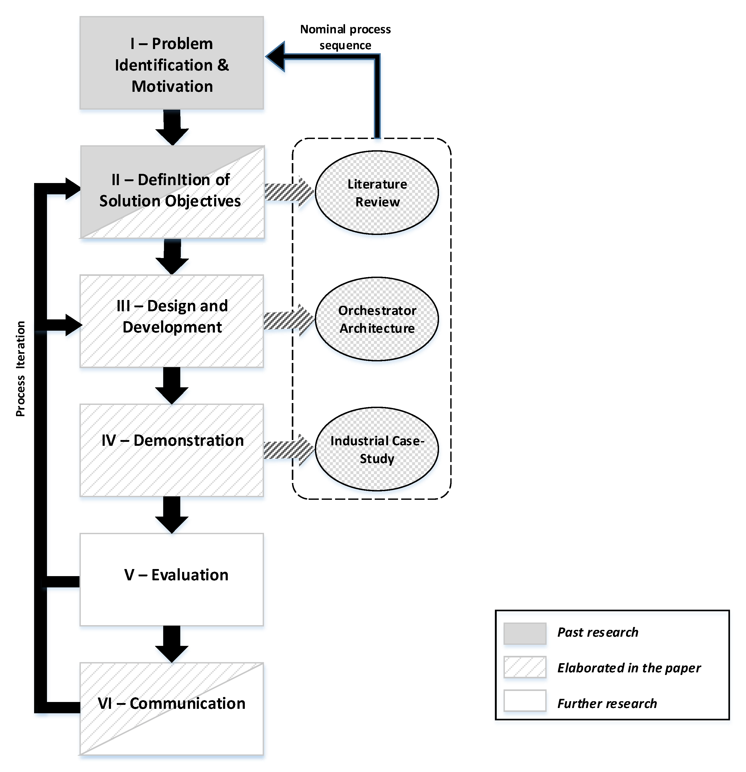
Table 1.
Shop floor resources.
| Resource ID | Resource Type | Capabilities |
|---|---|---|
| Operator1 | Operator 4.0 | Assemble, Inspect, Reassemble |
| Operator2 | Operator 4.0 | Assemble, Inspect |
| Cobot | Robot | Hold, Test |
| AssemblyRobot | Robot | Assemble, Test |
| AGV1 | Robot | Move, Carry |
| AGV2 | Robot | Move, Carry |
| MachineHolder | Machine | Hold |
Publisher’s Note: MDPI stays neutral with regard to jurisdictional claims in published maps and institutional affiliations. |
© 2021 by the authors. Licensee MDPI, Basel, Switzerland. This article is an open access article distributed under the terms and conditions of the Creative Commons Attribution (CC BY) license (https://creativecommons.org/licenses/by/4.0/).
Share and Cite
MDPI and ACS Style
Pisarić, M.; Dimitrieski, V.; Vještica, M.; Krajoski, G.; Kapetina, M. Towards a Flexible Smart Factory with a Dynamic Resource Orchestration. Appl. Sci. 2021, 11, 7956. https://0-doi-org.brum.beds.ac.uk/10.3390/app11177956
AMA Style
Pisarić M, Dimitrieski V, Vještica M, Krajoski G, Kapetina M. Towards a Flexible Smart Factory with a Dynamic Resource Orchestration. Applied Sciences. 2021; 11(17):7956. https://0-doi-org.brum.beds.ac.uk/10.3390/app11177956
Chicago/Turabian StylePisarić, Milan, Vladimir Dimitrieski, Marko Vještica, Goran Krajoski, and Mirna Kapetina. 2021. "Towards a Flexible Smart Factory with a Dynamic Resource Orchestration" Applied Sciences 11, no. 17: 7956. https://0-doi-org.brum.beds.ac.uk/10.3390/app11177956
Note that from the first issue of 2016, this journal uses article numbers instead of page numbers. See further details here.