Article

Performance Analysis of Fully Actuated Multirotor Unmanned Aerial Vehicle Configurations with Passively Tilted Rotors

1
Department of Mechanical Engineering, Karlovac University of Applied Sciences, 47000 Karlovac, Croatia
2
Department of Technology, Faculty of Mechanical Engineering and Naval Architecture, University of Zagreb, 10000 Zagreb, Croatia
3
Department of Robotics and Production System Automation, Faculty of Mechanical Engineering and Naval Architecture, University of Zagreb, 10000 Zagreb, Croatia
*
Author to whom correspondence should be addressed.
Appl. Sci. 2021, 11(18), 8786; https://doi.org/10.3390/app11188786
Submission received: 1 September 2021 / Revised: 17 September 2021 / Accepted: 20 September 2021 / Published: 21 September 2021
(This article belongs to the Special Issue Advances in Electric Propulsion Technology)

Abstract

:
Unmanned aerial vehicles (UAVs) nowadays represent an interesting tool capable of performing various missions. The multirotor type of UAV is proven to be a potential solution in missions that require precise movements, such as environmental objects manipulation. In this paper, a procedure for the performance analysis of fully actuated multirotor UAV configurations is proposed. For this purpose, a configuration is described by a control allocation scheme and implemented in the software package which enables the analysis and control implementation of a real system. The parameter analysis of the passively tilted multirotor configurations is performed based on the characteristics of the electric propulsion units, and the allocation of propulsion forces is graphically shown. The results of the proposed procedure provide an insight into the capabilities of configurations and can ultimately be used to select the propulsion system components and parameters according to the requirements and constraints associated with the specific mission profile. An experimental aircraft was built, and custom firmware was created, which enable us to experimentally prove the feasibility of fully actuated and passively tilted configurations.

1. Introduction

New technologies enable the development of mechatronic components and mechatronic systems found in many industries today. These mechatronic systems are also crucial for the development of unmanned aerial vehicles (UAVs). Since UAVs are no longer tied exclusively to military use, as they were in the past, their use in the civilian sector contributes to numerous applications and consequently increases in the market. Nowadays, UAVs can be used in many sectors such as surveillance [1], agriculture [2], construction [3], and many others. UAVs are also used in missions that involve the delivery of medical supplies, such as Zipline aircraft [4]. Depending on the applications, different types, different sizes, and various power ranges of aircraft are used. The general division can be made between fixed-wing aircraft and rotary-wing aircraft, so-called rotocopters. In addition to these two main types of UAVs, hybrid aircraft [5] and bioinspired aircraft, such as the Bat Bot (B2) [6], a biologically inspired flying machine, have also been increasingly investigated recently. In missions that require vertical and stationary flight, rotocopters are mainly used. There are two subtypes of rotocopters, aircraft with fixed-pitch propellers, so-called multirotors, and aircraft with variable pitch propellers whose typical representatives are helicopters.
The multirotor type of UAV can perform a vertical take-off and landing (VTOL), be stationary in the air, and perform movements at a moderate speed in a three-dimensional (3D) space. This makes this type of aircraft suitable for many specific applications, such as the inspection of wind turbine blades [7] or transmission lines [8]. From a control point of view, the multirotor type of UAV is an inherently unstable, nonlinear, and multivariable system. Such systems must necessarily include a flight controller (FC) unit that sends control signals to the aircraft propulsion system. Control methods for this type of aircraft are highly investigated, for example, in papers [9,10,11]. The multirotor configurations are determined by the design of the aircraft propulsion system consisting of N rotors. The rotors in the standard versions are actually the electric propulsion units (EPUs) which consist of a fixed-pitch propeller, brushless DC (BLDC) motor, and electronic speed controller (ESC). There are EPU components on the market that can be up to 10 kW per unit. Certain manufacturers additionally offer components intended for air transport with a power of a few tens of kW per unit [12]. Conventional multirotor configurations consist of an even number of rotors arranged in one or more parallel planes. The most common design is a four-rotor aircraft, better known as a quadrotor or quadcopter. The characteristic of conventional configurations is that they are underactuated, and it follows that such systems are also strongly coupled. This is disadvantageous in missions that involve precise and complex movements. Namely, conventional configurations need to change orientation in order to move in a 3D space. This can be overcome with non-planar geometric arrangements of multirotor configurations, such as OTHex aircraft [13].
By selecting the adequate geometric arrangement of the rotors, independent control of the system for each degree of freedom can be achieved, which enables decoupling of position control and orientation control. So far, fully actuated configurations with six passively tilted rotors are the most researched. The control of such systems [14] is considered, and full-pose tracking control for a fully controlled hexarotor with passively tilted rotors is presented in [15]. Since the performance of a multirotor aircraft depends on the parameters of the propulsion system, as seen in papers [16,17], the procedures of estimation, modeling, and the optimization of the parameters for a fully actuated hexarotor with tilted rotors are presented. Furthermore, fully actuated multirotor configurations are of interest to the research from the aspect of fault-tolerant control. In [18], the fundamental actuation properties such as force-moment decoupling, and fail-safe robustness were investigated. It follows from the cited literature that the fully actuated configurations were suitable for performing more precise and complex maneuvers in 3D space, and thus imposed themselves as favorable platforms in missions involving interaction and manipulation. In [19], 6D interaction control with a fully actuated hexarotor platform was experimentally tested. In addition to configurations with passively tilted rotors, a number of papers dealt with design, modeling, and the control of fully actuated configurations with various geometric arrangements, the so-called omnidirectional aerial robots [20,21].
In this paper, an approach to the performance analysis of fully actuated multirotor UAV configurations is presented. The approach is based on a structured mathematical model consisting of a control allocation scheme that describes the multirotor configuration. The implementation of the model in the software package enables a performance analysis for configurations with arbitrary parameters and is also the first step in determining the feasibility of the configuration. This step is important before designing the aircraft because it allows for the selection of system components and the parameters of the geometric arrangement of the rotors. A procedure for the analysis of the configuration parameters is proposed and the analysis of the distribution of the aerodynamic forces of EPUs on the force vector of the propulsion subsystem is presented. The results of the analysis, based on the characterized EPUs for fully actuated configurations with passively tilted rotors, are presented. Configuration parameter analysis is a necessary step that allows parameters to be optimized with respect to the requirements and constraints associated with the mission profile. Fully actuated hexarotor UAV control experiments are performed in order to validate configuration feasibility, and to set up a framework for experimental testing.

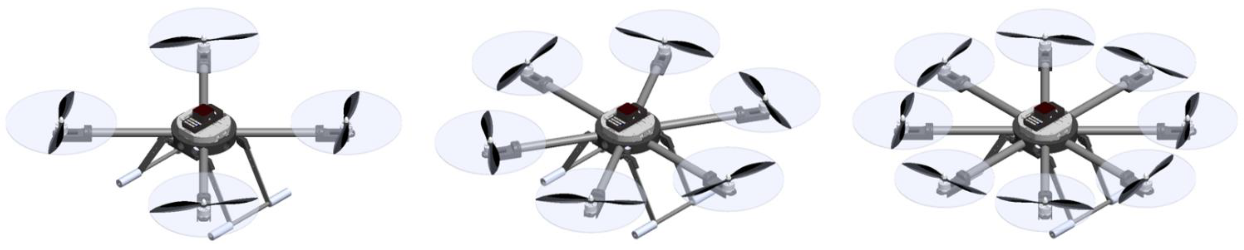
2. Mathematical Representation of Multirotor UAV Configurations

Multirotor UAV can be viewed as a rigid body with six DOF since it operates in a 3D space. Considering that a rigid body is an idealized form of invariant volume and shape, in which the mutual position of the particles is unchanging, the motion of a multirotor UAV can be described as the motion of a particle located in the aircraft center of gravity (COG). Therefore, the motion of a multirotor can be described by the translation and rotation of a particle with respect to a base station which is represented with the inertial coordinate system (often called the Earth frame, E , { O E ,   X E ,   Y E ,   Z E } ). The Earth frame is a right-handed Cartesian coordinate system fixed to the considered stationary point (on the Earth’s surface), where the Z axis has a positive direction defined as upwards from the ground level. Fixed-pitch propellers mounted on the motor rotors are the only moving parts, therefore multirotor UAV dynamics directly depend on the rotors’ angular velocities, where the stiffness of the propeller is assumed. Furthermore, the model is simplified through the assumption that the origin of the aircraft reference frame coincides with the COG and that the frame axes coincide with the multirotor main axes of inertia.
Common to all multirotor configurations is that they consist of N rotors. Their configuration is defined by the geometric arrangement of the rotors and by the characteristics of rotors (e.g., power). The design of multirotor configuration affects the performance and energy consumption of the system as a whole. Conventional configurations consist of an even number of rotors located in one or more parallel planes (so-called planar configurations) which are symmetrically arranged. In order to cancel the reactive moment around the vertical body axis, an equal number of rotors rotate in a clockwise (CW) and counterclockwise (CCW) direction. In addition to the most commonly used quadrotor, conventional configurations with six rotors (hexarotor) [22], and eight rotors (octorotor) [23] are often found in research and applications, where possible embodiments are shown in Figure 1. When more power is required in a compact aircraft, configurations with so-called coaxial rotor arrangements [24] or overlapping propulsion arrangements are used [25].
Apart from the aforementioned conventional configurations with a planar rotor arrangement, there are also many studies which deal with configurations with a non-planar geometric arrangement. In [26], a novel and more efficient multirotor configuration with four rotors is presented. There is a whole range of research on passively tilted hexarotors [14,15,16,17,18,19] which are the most common representative of fully actuated configurations.

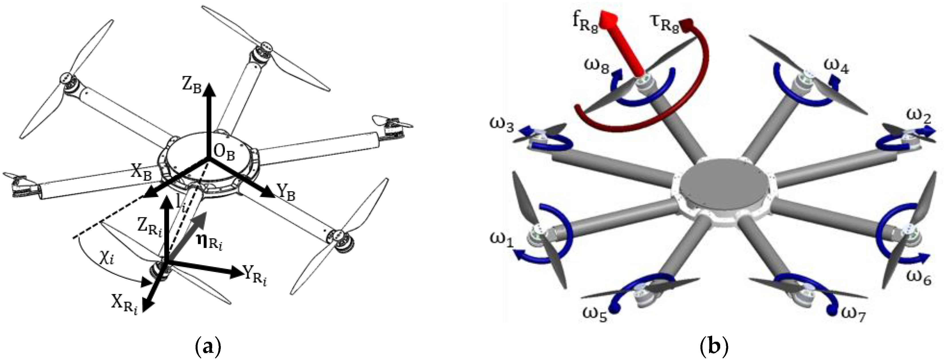
2.1. Dynamics of a Multirotor UAV

In order to obtain a representative aircraft model, in addition to mathematical description of multirotor configurations, a brief description of the multirotor UAV dynamic model is given. To begin with, it is necessary to define the aircraft coordinate system (called Body frame, B , { O B ,   X B ,   Y B ,   Z B } ) as shown in Figure 2a. The Body frame is fixed to the multirotor UAV body where the origin coincides with the COG, and axes coincide with the multirotor main axes of inertia. In the Body frame, the velocities for each DOF of the aircraft are defined as ν = [ u v w p q r ] T , respectively, translational v B = [ u v w ] T and rotational ω B = [ p q r ] T velocities. It follows that the equations of motion are also defined in the Body frame. A system model of six second-order differential equations is obtained based on the Newton–Euler approach, described in more detail in previous research [27,28]. The equations of motion given in the matrix form are defined by the following expression:
M B ν ˙ + C B ( ν ) ν = Λ ,
where M B represents a rigid body inertia matrix which comprises multirotor UAV mass m , and the body’s inertia matrix I = diag { I xx , I yy , I zz } . The next element on the left side of the equation represents the Coriolis and centripetal matrix C B ( ν ) , which describe the inertial forces with respect to the rotating body frame [29]. To the right of the equation is the vector of forces and moments Λ acting on the aircraft rigid body.
The dynamic of a multirotor UAV is influenced by the forces and moments of the environment and the propulsion of the aircraft. In this brief description of the dynamics, four elements are considered which affect the aircraft dynamics. Overall, the vector of forces and moments is given with the following expression:
Λ = d + g B + o B + u B ,
where d is the disturbance vector which contains external disturbances, for instance, wind gusts and unmodelled dynamics. The gravitational force vector g B acts only on translational dynamics and can be accurately described since it acts in the vertical axis of the Earth frame. As a consequence of the rotors’ velocities, a gyroscopic moment vector o B is included in the model which acts only on rotational dynamics. The last vector u B represents the forces and moments of the propulsion system with respect to the Body frame.
Changing the rotor angular velocities directly affects the multirotor UAV dynamics. Therefore, the propulsion vector is called a control vector and consists of three forces f = [ f X f Y f Z ] T which act on translational dynamics, and three moments τ = [ τ ϕ τ θ τ ψ ] T which act on rotational dynamics. The control vector u B = [ f X f Y f Z τ ϕ τ θ τ ψ ] T comprises six elements, one for each DOF, and is given by the following expression:
u B = Γ B Ω ,
where Γ B is the matrix of the control allocation scheme. The matrix contains multirotor UAV configurations parameters which can be divided into propulsion geometric arrangement parameters and propulsion unit characteristics. Since propulsion forces and moments are considered as proportional to the square of the rotors’ angular velocities, a vector is represented as Ω = [ ω 1 2   ω 2 2   ω N 2 ] T , where N is a number of rotors.

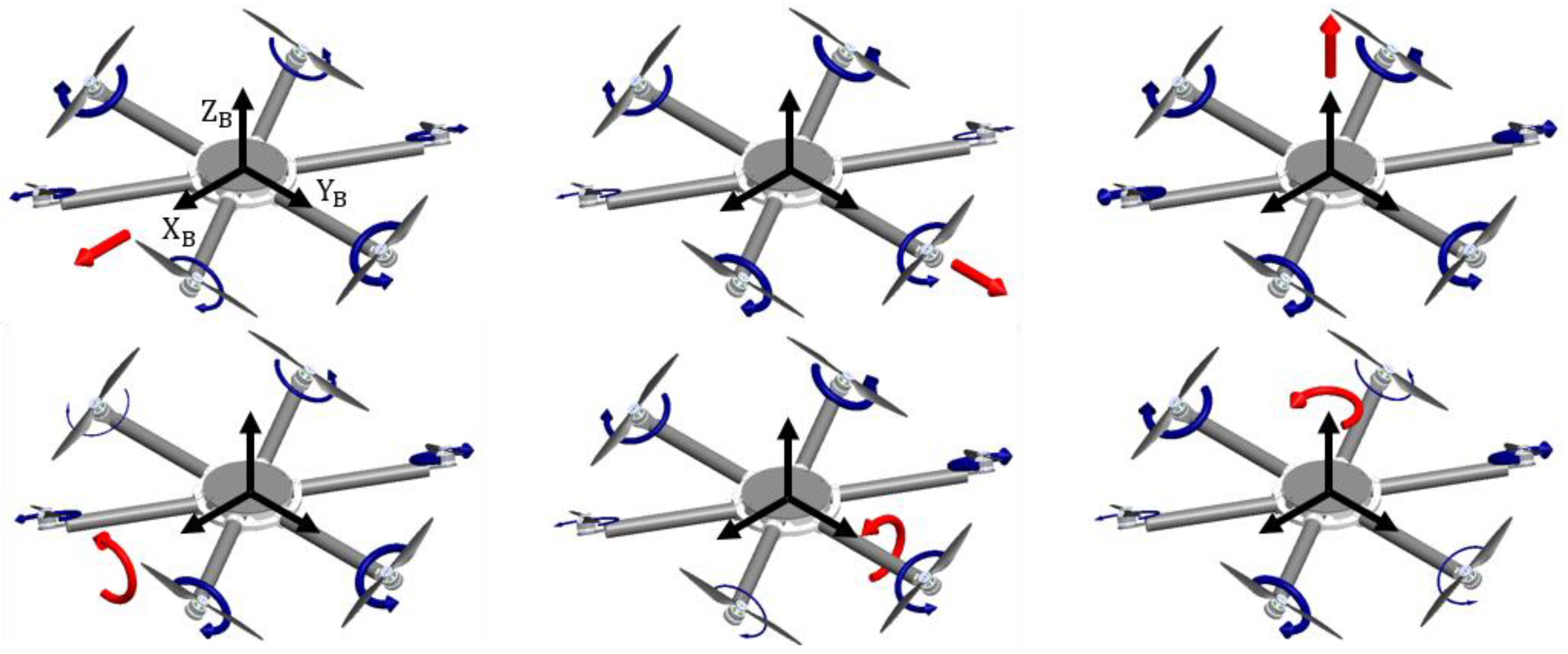
2.2. Multirotor Configuration Control Allocation Scheme

Propellers mounted on rotors by their rotation generate the aerodynamic forces and moments required for the multirotor UAV motion. The control allocation scheme defines the multirotor configuration in a way that describes the mapping of the rotors’ angular velocities to the aircraft control vector. The multirotor propulsion configuration, which consists of N rotors, is determined by the rotors’ geometric arrangement parameters (EPUs) and their characteristics. The geometric arrangement is defined by the vector of the position and orientation of each rotor. For this purpose, it is necessary to determine for each rotor its coordinate system ( R i , { O R i ,   X R i ,   Y R i ,   Z R i } ) whose X R i Y R i plane is parallel to the aircraft plane X B Y B , as it is shown in Figure 2a.
The propulsion configuration position vector of i-th rotor ξ R i is defined by the length of the rotor arm l i and the angle of the rotor arm χ i , as shown in Figure 2. The equation is defined based on a rotation matrix R R i T ( χ i ,   Z B ) which describes the rotation of the rotor arm around the aircraft axis Z B for the angle χ i . The position vector of the i-th rotor is given by the following expression:
ξ R i = R R i T ( χ i ,   Z B ) [ l i 0 0 ] .
This expression is characteristic of configurations whose rotors are bblocated in the X B Y B plane, which is typical for conventional configurations with a planar arrangement in one plane. If the rotors are arranged on parallel planes, then the third coordinates of the input vector depend on the distance of the rotor’s plane X R i Y R i from the aircraft plane X B Y B as [ l i 0 z R i ] T .
As previously described, conventional configurations are characterized by a planar arrangement of rotors which means that the rotational axes of all the rotors are parallel to the aircraft axis Z B ; therefore, the orientation vector of every rotor is a unit vector η R i = e 3 = [ 0 0 1 ] T . Since there are also non-planar configurations, where special emphasis is placed on fully actuated configurations, it is necessary to define the orientation vector. The orientation vector definition is given by the following expression:
η R i = R R i T ( χ i , Z B ) R R i T ( β i ,   Y R i ) R R i T ( γ i ,   X R i ) e 3 ,
where β i is the i-th rotor cant angle around the Y R i axis, and γ i is the i-th rotor tilt angle around the X R i (rotor arm) axis. The last term of the equation on the right side is the unit vector e 3 since the aerodynamic forces and moments of the rotor are defined with respect to the axis of rotation Z R i . The parameters of the configurational geometric arrangement determine the allocation of the rotors’ aerodynamic forces and moments on the aircraft control (propulsion) vector.
The characteristics of the rotor depends on the EPU components, which consist of a fixed-pitch propeller, BLDC motor, and ESC. The EPU enables a precise and fast control and is very reliable, reducing the possibility of a crash. This type of propulsion system is suitable for a very wide range of applications, given that there is a large selection of components on the market. The central part of the EPU is a BLDC motor since it consists of a fixed section (stator) and a movable, rotating section (rotor). There are two BLDC motor design types, where a design which is almost always used in multirotors has the motor rotor positioned outside the stator (so-called outrunner). The aerodynamic effects are generated by the rotation of the fixed-pitch propeller, which is mounted to the motor rotor. It is assumed that the aerodynamic effects consist of the thrust force and the drag torque, while the other effects are neglected.
The required thrust force and the drag torque are achieved by changing the angular velocity of the rotor. Increasing the propeller geometry parameters, such as the diameter or pitch angle or number of propeller blades, results in a larger airflow. Respectively, at the same angular velocity (RPM), the rotor assembly will create a greater thrust force which is modeled as proportional to the square of the rotor angular velocity ω i . The thrust force of the i-th rotor is defined with the following expression:
f R i = k f i ω i 2 ,
where k f i is the thrust force factor which depends on the propeller geometry and the air density ρ .
As a consequence of the greater thrust force, the resistance to rotation is greater, therefore producing a greater motor drag torque. The load on the i-th motor is imposed by drag torque and can be defined with the following expression:
τ R i = k τ i ω i 2 ,
where k τ i is the drag torque factor which depends on the geometry of the propeller, the air density, and the motor power.
The selection of components is an important step in the design of the aircraft since the dynamics of the aircraft depend on the characteristics of the components, as well as its energy consumption. Very often, component manufacturers provide detailed specifications for the recommended propeller and motor setups. BLDC motor is a permanent-magnet electric motor where electromagnets (armature) are located on the stator of the motor, while permanent magnets are located on the driven rotor shell. This type of motor is driven by ESC which represents an electronic commutation system with rectangular-shaped voltage signals. The ESC is an integrated power inverter that processes the input PWM signal from the FC in order to set the adequate speed of the transistors’ switching sequence. It converts input DC voltage into the appropriate phase voltages by which it energizes particular phases of a motor and achieves the desired rotor angular velocity. With a higher duty cycle of the PWM signal, the voltage is increased, therefore rotor angular velocity also increases.
Once the geometric arrangement of the rotor and the characteristics of the rotor are described, the force and moment vectors of the i-th rotor, with respect to the Body frame, can be defined. The rotor force vector is obtained by mapping the rotor thrust force through the orientation vector, and is given by the expression:
f i = ( k f i η R i ) ω i 2
The rotor moment vector consists of two components, where the first one arises from the action of the thrust force and the second one arises from the action of the drag torque. The moment vector of the i-th rotor is derived using the matrix representation of the vector product a × b = S ( a ) b :
τ i = ( k f i S ( ξ R i ) η R i + k τ i η R i ) ω i 2
The sign of drag torque factor k τ i depends on the rotor angular velocity direction. Rotors with a CW direction have a positive sign, while CCW rotors have a negative sign.
The control allocation matrix ( Γ B 6 × N ), which contains the propulsion geometric arrangement parameters and the EPU characteristics, is presented with the following expression:
Γ B = [ k f 1 η R 1 k f N η R N k f 1 S ( ξ R 1 ) η R 1 + k τ 1 η R 1 k f N S ( ξ R N ) η R N + k τ N η R N ]
Since the multirotor has six DOF, the control allocation matrix consists of six rows, one for each DOF, while the number of matrix columns is equal to the number of rotors, N. The control allocation defined in this way is a useful tool from the aspect of determining the degree of system actuation. The matrix rank determines the number of controlled DOF which is key information for the control design and flight planning.
As mentioned, conventional configurations are characterized by a planar arrangement of the rotors in one or more parallel planes. It follows that the orientation vector is a unit vector and, as a result, the matrix rank is not of full order. Regardless of the number of rotors, such configurations are underactuated systems. The following matrix describes a conventional X-shaped hexarotor (X6):
Γ X 6 = [ 0 0 0 0 0 0 0 0 0 0 0 0 k f k f k f k f k f k f k f l k f l 1 2 k f l 1 2 k f l 1 2 k f l 1 2 k f l 0 0 3 2 k f l 3 2 k f l 3 2 k f l 3 2 k f l k τ k τ k τ k τ k τ k τ   ]
The considered configurations have the same length ( l ) as the rotor arms on which the same EPUs with the factors of thrust force ( k f ) and drag torque ( k τ ) are mounted. Regarding the control of conventional configurations, there are two basic cases. The first case is related to remote control where the operator controls thrust, roll, pitch, and yaw. The second case is related to the autonomous flight and position control [9] where aircraft position is controlled by changing propulsion moments.
To achieve the full rank of the allocation matrix, it is necessary to accordingly select the parameters of the configuration geometric arrangement, specifically the parameters of the rotor orientation. The allocation matrix for a hexarotor with passively tilted rotors (PTX6) is given:
Γ PTX 6 = [ k f s γ k f s γ 1 2 k f s γ 1 2 k f s γ 1 2 k f s γ 1 2 k f s γ 0 0 3 2 k f s γ 3 2 k f s γ 3 2 k f s γ 3 2 k f s γ k f c γ k f c γ k f c γ k f c γ k f c γ k f c γ k f lc γ + k τ s γ k f lc γ k τ s γ 1 2 k f lc γ 1 2 k τ s γ 1 2 k f lc γ + 1 2 k τ s γ 1 2 k f lc γ + 1 2 k τ s γ 1 2 k f lc γ 1 2 k τ s γ 0 0 3 2 k f lc γ + 3 2 k τ s γ 3 2 k f lc γ 3 2 k τ s γ 3 2 k f lc γ + 3 2 k τ s γ 3 2 k f lc γ 3 2 k τ s γ k f ls γ + k τ c γ k f ls γ k τ c γ k f ls γ + k τ c γ k f ls γ k τ c γ k f ls γ k τ c γ k f ls γ + k τ c γ ] ,
where c γ = cos ( γ ) ,   s γ = sin ( γ ) . The allocation matrix of such configuration has the full rank; therefore, the configuration is fully actuated, so multirotor UAV can accelerate in any direction in space. A necessary prerequisite for fully actuated configurations is that they consist of a minimum of six rotors.

2.3. Inverse Control Allocation Scheme

To implement a control system on a real custom aircraft with various configuration parameters, it is necessary to derive the inverse control allocation scheme to allow the allocation of control algorithm outputs to the rotors’ angular velocities. The inverse allocation scheme also enables the analysis of configuration parameters which are shown later through the proposed procedure. Since a configuration with more or less than six rotors is not represented with a square allocation matrix, rotors’ angular velocities are thus calculated using pseudoinverses as given with the following expression:
Ω = Γ B T ( Γ B Γ B T ) 1 u B
The inverse allocation scheme for a hexarotor with passively tilted rotors ( Γ PTX 6 ) is given with the expression (14). Figure 3 schematically shows the magnitudes of the rotors’ angular velocities for all six controllable DOF. An inverse allocation scheme for a passively tilted octorotor ( Γ PTX 8 ), as shown in Figure 2b, is given with the expression (15).
[ ω 1 2 ω 2 2 ω 3 2 ω 4 2 ω 5 2 ω 6 2   ] = [ 1 3 k f s γ 0 1 6 k f c γ 1 3 ( k f lc γ k τ s γ ) 0   1 6 ( k f ls γ + k τ c γ ) 1 3 k f s γ 0 1 6 k f c γ 1 3 ( k f lc γ k τ s γ ) 0   1 6 ( k f ls γ + k τ c γ ) 1 6 k f s γ 3 6 k f s γ 1 6 k f c γ 1 6 ( k f lc γ k τ s γ )   3 6 ( k f lc γ k τ s γ )   1 6 ( k f ls γ + k τ c γ ) 1 6 k f s γ 3 6 k f s γ 1 6 k f c γ 1 6 ( k f lc γ k τ s γ )   3 6 ( k f lc γ k τ s γ )   1 6 ( k f ls γ + k τ c γ ) 1 6 k f s γ 3 6 k f s γ 1 6 k f c γ 1 6 ( k f lc γ k τ s γ )   3 6 ( k f lc γ k τ s γ )   1 6 ( k f ls γ + k τ c γ ) 1 6 k f s γ 3 6 k f s γ 1 6 k f c γ 1 6 ( k f lc γ k τ s γ )   3 6 ( k f lc γ k τ s γ )   1 6 ( k f ls γ + k τ c γ ) ] [ f x f y f z τ ϕ τ θ τ ψ   ] ,
[ ω 1 2 ω 2 2 ω 3 2 ω 4 2 ω 5 2 ω 6 2 ω 7 2 ω 8 2   ] = [ 2 2 8 k f s γ 2 + 2 8 k f s γ 1 8 k f c γ 2 2 8 ( k f lc γ k τ s γ ) 2 + 2 8 ( k f lc γ k τ s γ ) 1 8 ( k f ls γ + k τ c γ ) 2 2 8 k f s γ 2 + 2 8 k f s γ 1 8 k f c γ 2 2 8 ( k f lc γ k τ s γ ) 2 + 2 8 ( k f lc γ k τ s γ )   1 8 ( k f ls γ + k τ c γ ) 2 + 2 8 k f s γ 2 2 8 k f s γ 1 8 k f c γ 2 + 2 8 ( k f lc γ k τ s γ )   2 2 8 ( k f lc γ k τ s γ )   1 8 ( k f ls γ + k τ c γ ) 2 2 8 k f s γ 2 + 2 8 k f s γ 1 8 k f c γ 2 2 8 ( k f lc γ k τ s γ ) 2 + 2 8 ( k f lc γ k τ s γ )   1 8 ( k f ls γ + k τ c γ ) 2 2 8 k f s γ 2 + 2 8 k f s γ 1 8 k f c γ 2 2 8 ( k f lc γ k τ s γ )   2 + 2 8 ( k f lc γ k τ s γ )   1 8 ( k f ls γ + k τ c γ ) 2 + 2 8 k f s γ 2 2 8 k f s γ 1 8 k f c γ 2 + 2 8 ( k f lc γ k τ s γ ) 2 2 8 ( k f lc γ k τ s γ )   1 8 ( k f ls γ + k τ c γ ) 2 + 2 8 k f s γ 2 2 8 k f s γ 1 8 k f c γ 2 + 2 8 ( k f lc γ k τ s γ )   2 2 8 ( k f lc γ k τ s γ )   1 8 ( k f ls γ + k τ c γ ) 2 + 2 8 k f s γ 2 2 8 k f s γ 1 8 k f c γ 2 + 2 8 ( k f lc γ k τ s γ )   2 2 8 ( k f lc γ k τ s γ )   1 8 ( k f ls γ + k τ c γ ) ] [ f x f y f z τ ϕ τ θ τ ψ   ] ,
The presented multirotor UAV model is implemented in a software package and can be used to simulate the multirotor UAV performance with certain configuration parameters, with respect to reference behavior. This model is further used in the analysis of the configuration parameters, shown in the next chapter. Furthermore, the inverse of the control allocation scheme can be simplified to make it easier for implementation in a real aircraft.

3. Performance Analysis Procedure and Results

The multirotor UAV configuration, more precisely the configuration of the propulsion system should ensure the required flight performance according to the type of mission for which the aircraft is intended. It follows that the selection of configuration parameters and the components themselves, e.g., propulsion units, are a key step in the design of this type of UAV. Since the geometric parameters of the configuration were previously described by a mathematical model, to execute the analysis it was necessary to perform a characterization for the selected propulsion units. Five setups of EPUs shown in Table 1 were selected and further considered for the purposes of configuration parameter analysis. In this paper, the characterization of EPU was performed by the methodology presented in the last phase of the research [27]. The characterization can be based on the manufacturer’s specifications, and for a more precise procedure, it is better to perform experimental measurements.
The first step of characterization is the identification of parameters that can be divided into mechanical and electrical quantities. Mechanical quantities are further considered, which are related to aerodynamic effects and rotor revolutions per minute (RPM), e.g., angular velocity. Experimental measurements were performed using a RCbenchmark 1580 measurement system [30]. After processing, the measurement results are saved in data series and displayed as static maps. Figure 4 shows static maps of aerodynamic effects as functions of the input PWM signal. Respectively, Figure 4a shows the thrust forces, and Figure 4b the drag torques, for considered EPU setups. It can be seen that the thrust forces are the dominant aerodynamic effect which is an important aspect for the further implementation of parameter analysis. As expected, EPU setups with lower K v , paired with larger propeller diameters, achieve higher aerodynamic forces and torques.
The next step is the EPU characterization, which is carried out on the basis of static maps for five considered EPU setups. In this step, the aim is to present and estimate the factors of aerodynamic effects: the thrust force factor k f and the drag torque factor k τ , respectively. Figure 5 shows thrust force and drag torque characteristics with respect to rotor angular velocity. As can be seen from the obtained curves, the thrust forces and drag torques are approximately proportional to the square of the rotors’ angular velocities; thus validating Equations (6) and (7). This fulfills the prerequisites for conducting a configuration performance analysis and enables computer simulations of the multirotor UAV behavior.

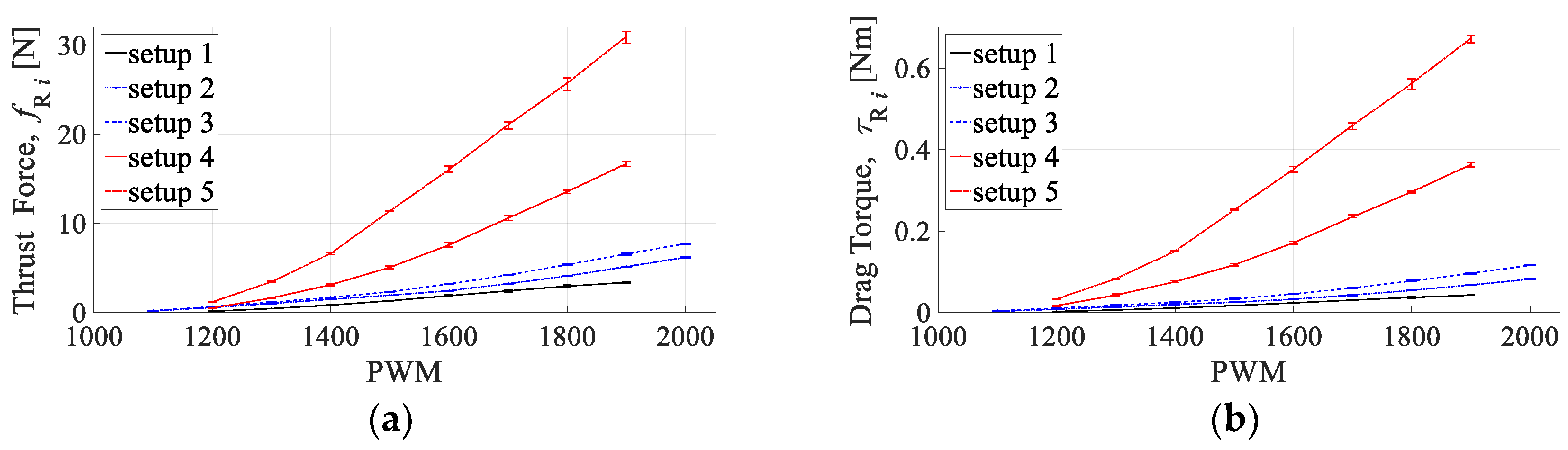
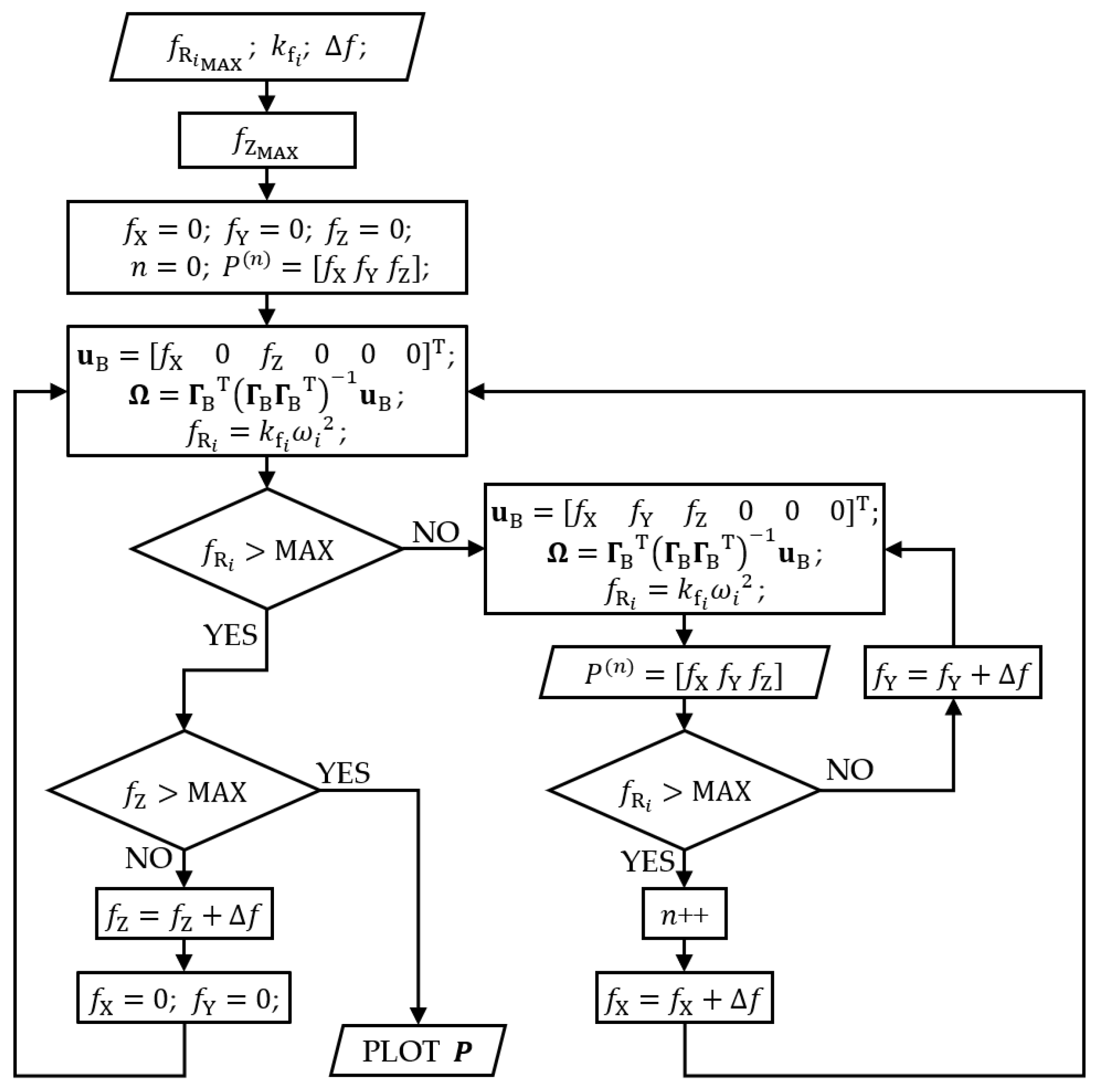
3.1. Performance Analysis Procedure

The distribution of propulsion aerodynamic forces and moments on the control vector of the aircraft depends primarily on the configuration of the geometric arrangement. Since the paper considers fully actuated configurations, a mathematical model shows that a full degree of actuation can be achieved by choosing proper configuration parameters. As can be seen from the propulsion units’ characteristics, the dominant role in the aircraft dynamics is played by the thrust forces. The distribution of the thrust forces is determined by the orientation of the rotors which, alongside rotor position, determines the distribution of thrust forces and drag torques on the control moments. Configurations with passively tilted rotors are considered, whose signs of the tilt angles are chosen in order to achieve the full rank of the allocation matrix in a fully actuated system. When choosing a geometric arrangement, it is important to keep the balance of the aircraft, in other words, the static equilibrium.
In this paper, a procedure for analyzing multirotor configuration parameters is proposed. Specifically, the influence of the geometric arrangement of passively tilted rotors on the distribution of thrust forces is numerically analyzed with the MATLAB software package. The analysis procedure is an iterative algorithm based on the implementation of a derived inverse control allocation scheme. In every iteration, aircraft forces, f X , f Y and f Z   , are independently and successively incremented until the calculated thrust force on any rotor exceeds the experimentally determined maximum value. A simplified flowchart of the analysis procedure is shown in Figure 6, where an iterative algorithm is accomplished with three nested loops, one for each force iteration.
At the beginning of the iterative algorithm, the maximum value for f Z is obtained from the known maximal thrust force and rotors orientation. Since observed rotors cannot spin in the reverse direction, the f Z value will always be positive or 0 when the rotors do not rotate. While in the f Z loop, the algorithm will enter the f X loop and increment f X until the maximal thrust force is reached on any rotor. For every increment of f X , an f Y loop is entered, in which f Y is increased until the maximal thrust force is reached. Upon exiting the f Y loop, the values of forces in all three directions are saved as 3D point coordinates, respectively. When f Y and f X reach maximum values, f Z will increase and f X and f Y loops will be repeated again. When the maximum value of f Z is reached, the iteration is finished, and the 3D cloud of points is generated.
The iterative algorithm shown in the simplified flowchart starts at forces set to zero and successively increases them. Hence, one run of the algorithm will provide the full results for f Z , but only partial results for f X and f Y (as can be seen in Figure 7).
Since multirotors can move forward and backward, and left and right, considering only positive values of f X and f Y will give limited results in only one quadrant. The iteration algorithm can easily be extended to results in all four quadrants by including another f X loop below the existing one, which will now decrease f X until the thrust limit is reached, and similarly, another for f Y loop which will now decrease for f Y and save the values of all three forces when the thrust force limit is reached on any rotor.
However, for some cases, even limited results can provide the full information regarding the distribution of thrust forces. This depends upon the symmetry characteristics of the aircraft rotors’ geometric arrangements. Almost all aircraft are symmetrical along the X B axis, since it is desirable to achieve equal responses to the left and right movement, hence, the distribution of the thrust forces will also be symmetrical, concerning the X B axis. The same applies to the Y B axis symmetry. Hence, for an aircraft with a symmetrical rotors’ geometric arrangement concerning X B and Y B axis, even the limited results of one quadrant are sufficient for full distribution of thrust forces. However, aircraft without symmetry along Y B are not rare. The example results shown in Figure 7 are based on a PTX6 configuration, and fall into this category of aircraft with only X B axis symmetry; hence, the distribution of thrust forces will depend upon the direction of f X .
The output result of the analysis procedure explained above generates a cloud of points where every point represents the maximally available thrust forces in a particular direction. Instead of the cloud of points, which are more convenient for the visualization of the numerical part of the analysis procedure, boundary surfaces obtained by merging all the points make it easier to visualize the distribution of thrust forces. Therefore, the method with boundary surfaces is used to represent the results given in the forward subsection.

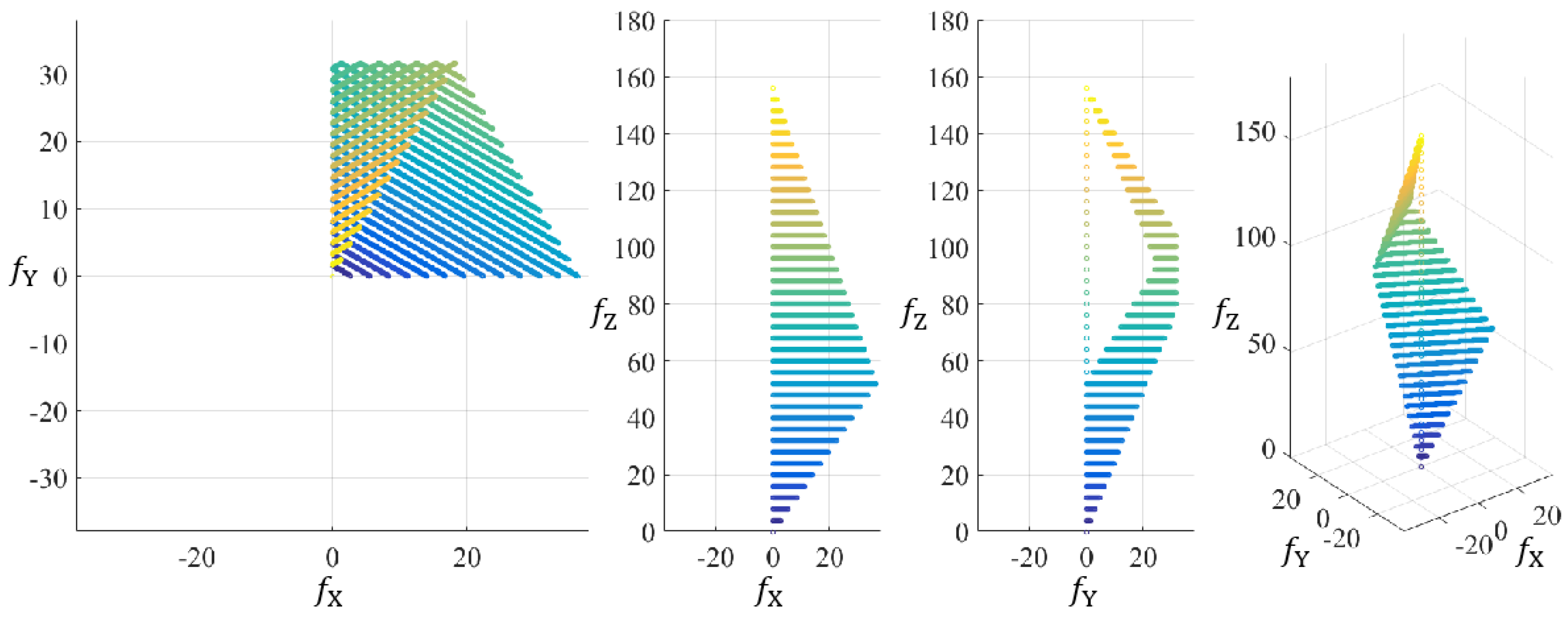
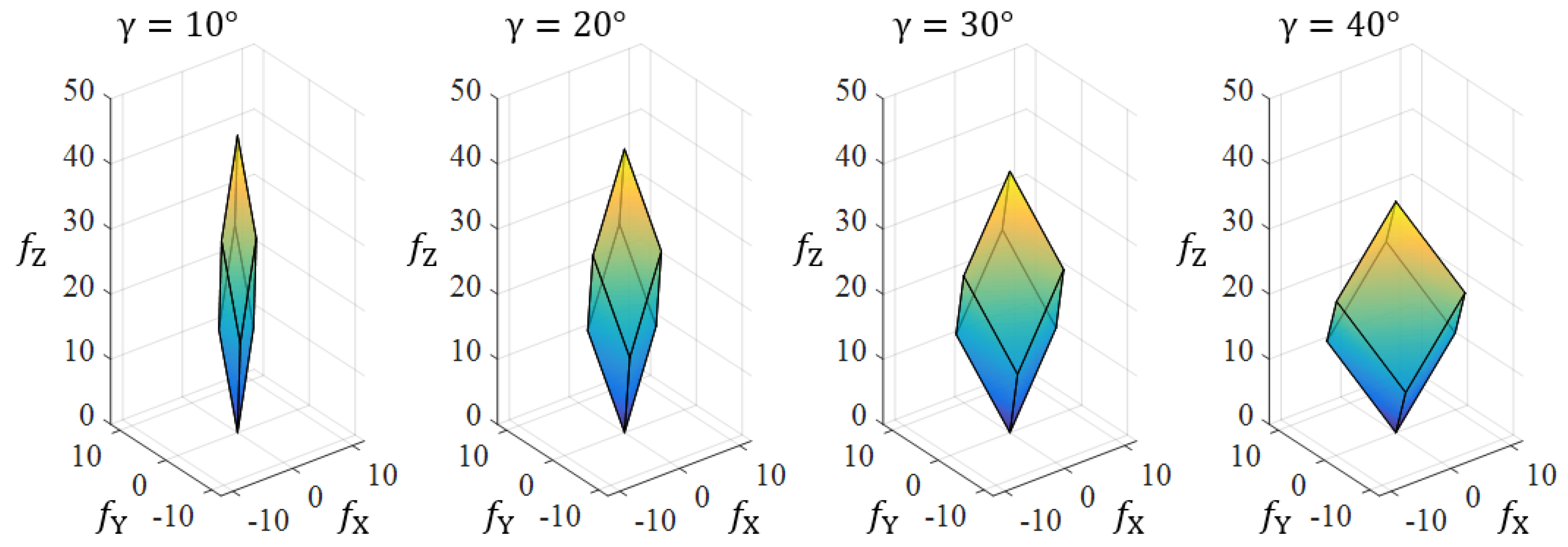
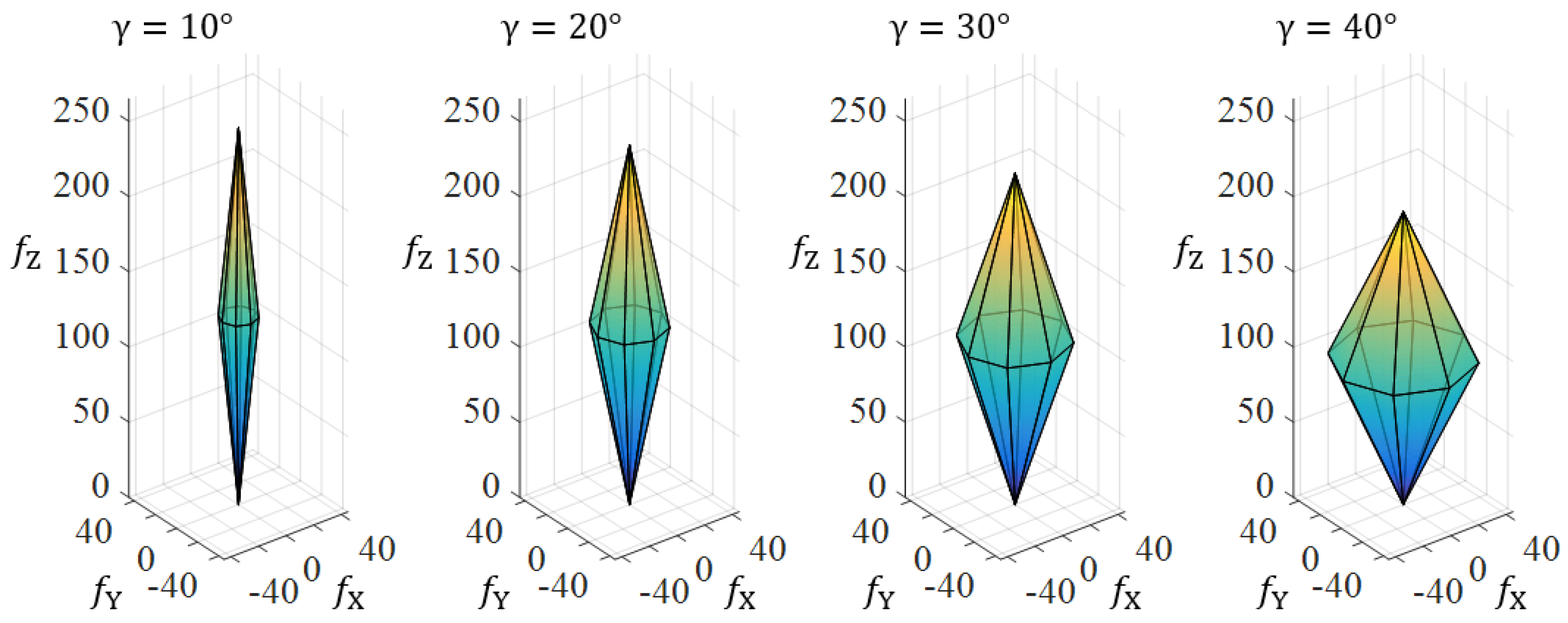
3.2. Results of the Tilt Angle Analysis

The results of the analysis of the rotors’ tilt angles, and their influence on the distribution of thrust forces to the control vector, are presented. In order to perform the analysis, it is necessary to define the input configuration parameters, which are considered symmetrical, consisting of an even number of passively tilted rotors. All rotor arms are of the same length, and all rotors consist of the same components. The input parameter is the characteristic of the propulsion unit, more precisely the maximum thrust force. The results for the two configurations are presented, first for PTX6 consisting of setup 3 EPUs, and then for PTX8 consisting of setup 5 EPUs. Given the selected geometric arrangement, the motion of the aircraft in 3D space can be realized by generating vertical and horizontal forces in the Body frame. Fully actuated configurations with passively tilted rotors have the margins of forces in the form of a polyhedral. In the six-rotor configuration (PTX6), the polyhedron is bounded by six rhombuses (Figure 8), while in the eight-rotor configuration (PTX8) it is bounded by sixteen triangles (Figure 9). Figure 8 and Figure 9 show the results of the performed analysis for the amount of tilt angles from 10 to 40°, where forces are expressed in newtons.
Therefore, maintaining the required performance of stationary and vertical flight requires a higher energy consumption, and thus reduces flight time. On the other hand, the amount of the horizontal force component increases so that the aircraft is able to perform horizontal movements without the need to change orientation. Performed analysis can be further expanded and used to investigate the energy consumption, agility, the effects of the size (power) of the aircraft, the rejection of disturbances, among others.

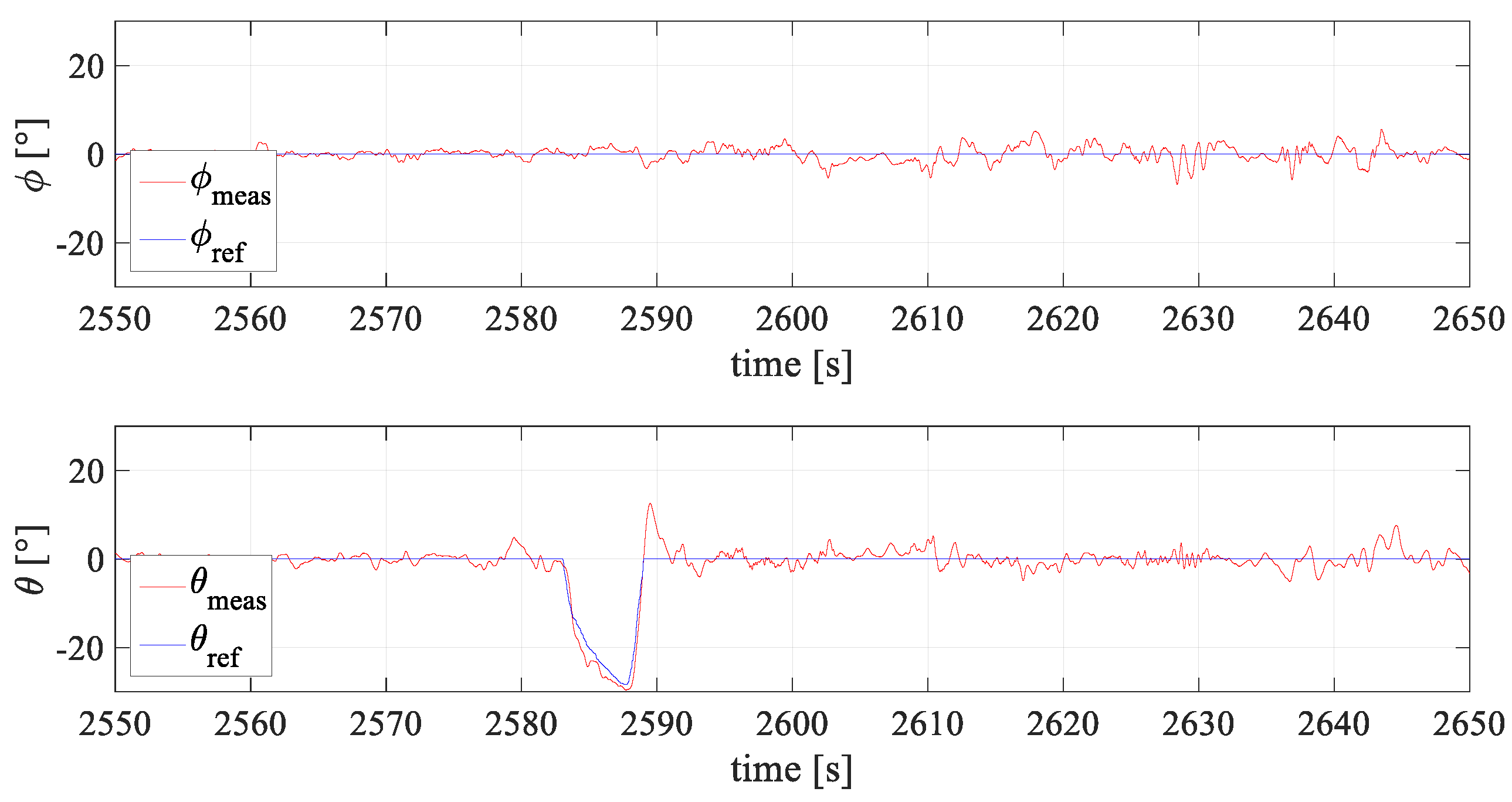
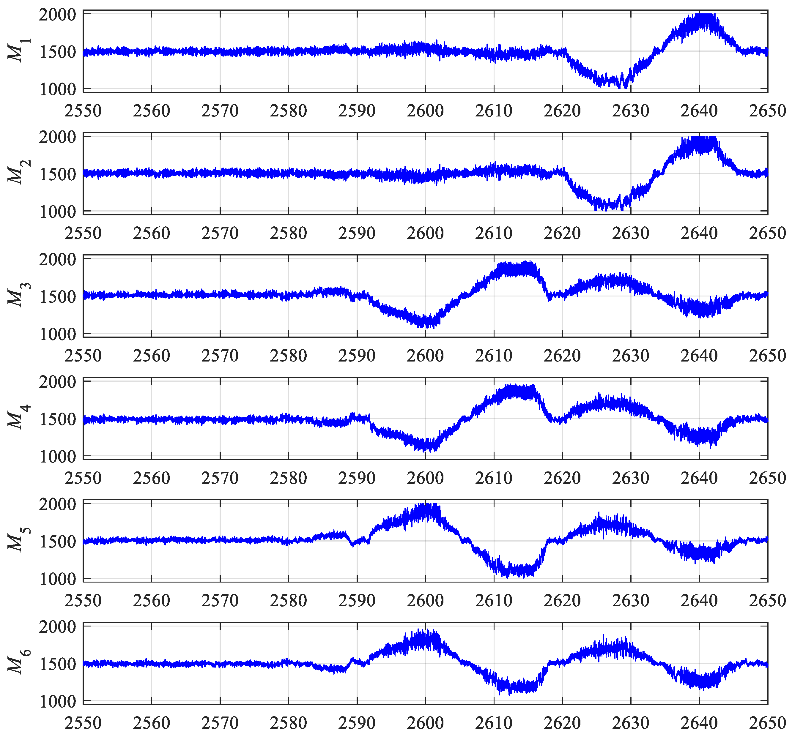
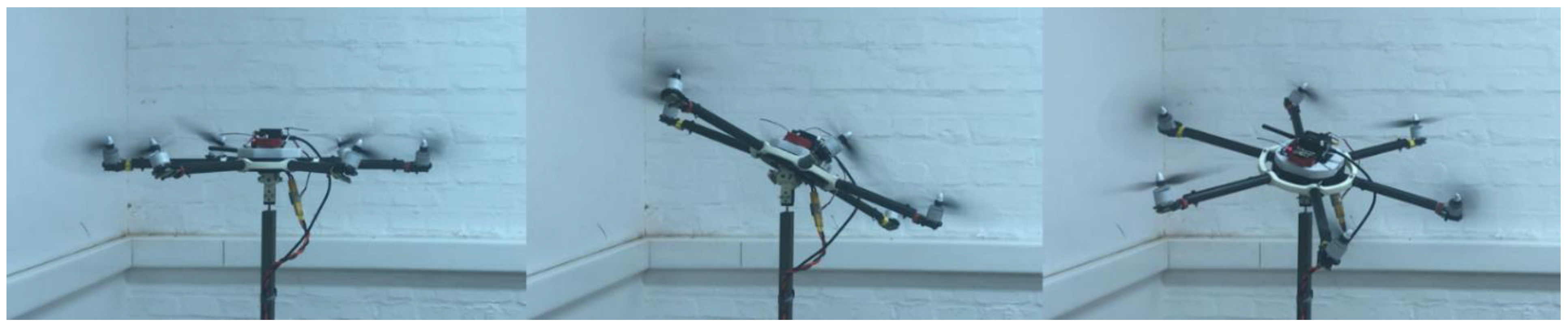
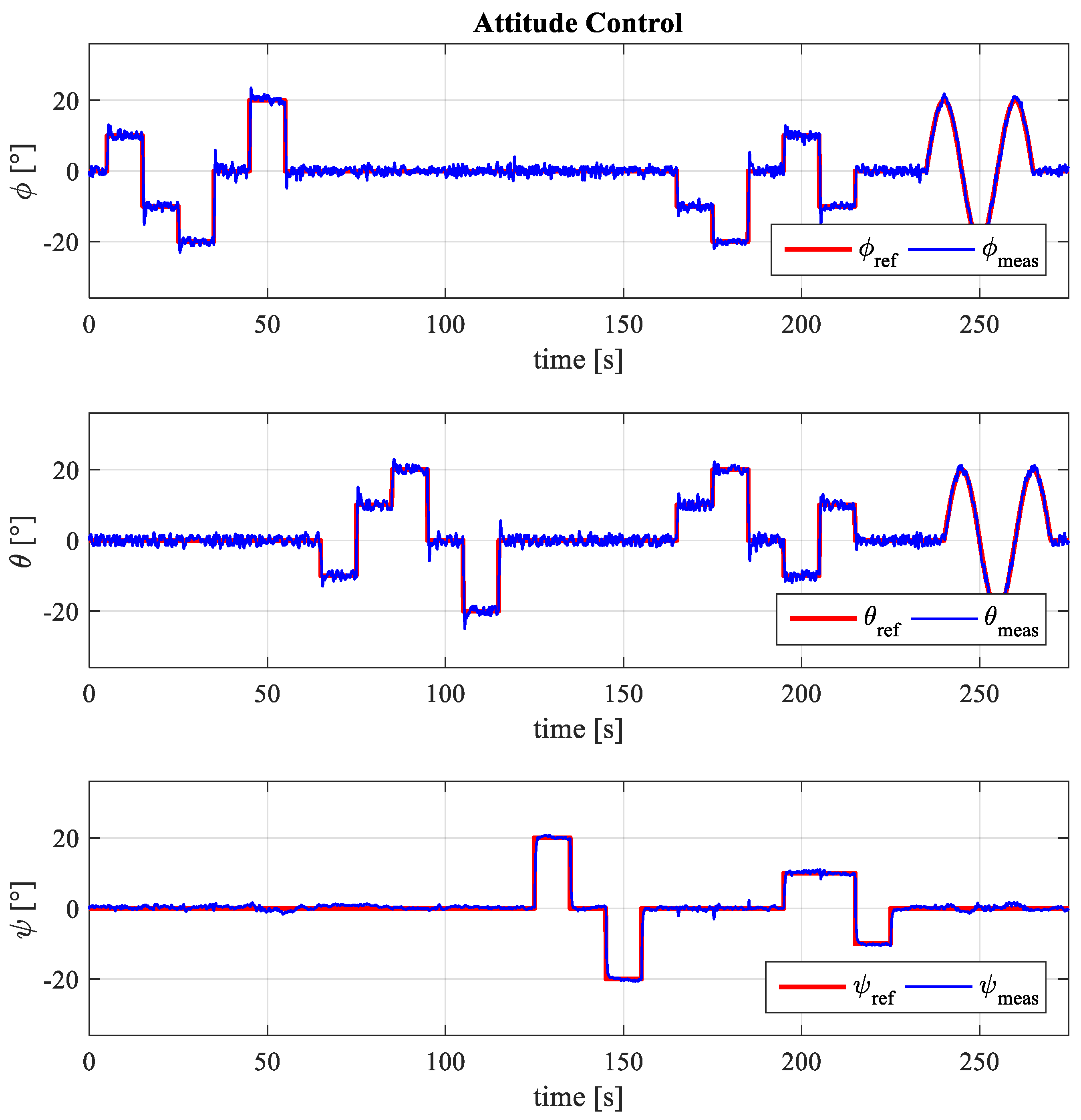
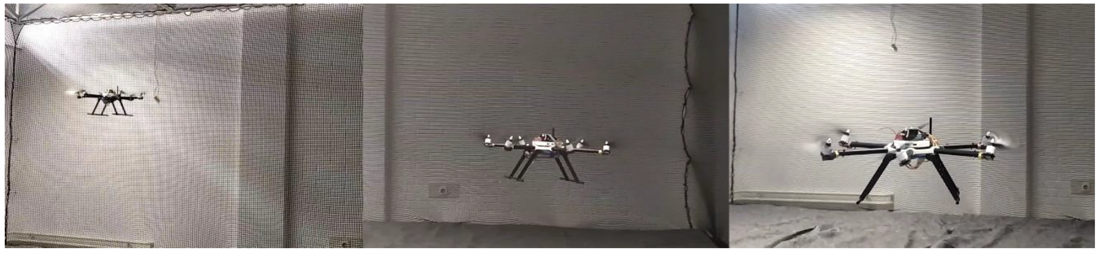
4. Experimental Validation Framework

For the purpose of the experimental validation of the presented model and the proposed procedure for the analysis of configuration parameters, it is necessary to realize an experimental aircraft and experimental firmware. The experimental aircraft was designed in the SOLIDWORKS software package (Dassault Systèmes SE, Vélizy-Villacoublay, France). As mentioned before, the aircraft assembly consists of four modules. The modular approach to aircraft design aims to enable the easy assembly of the aircraft and the propulsion module with a different number of rotors. Rapid prototyping technologies are used in the development phase where important requirements are high strength and the rigidity of parts and low specific weight. The parts are made from composite plates utilizing a 3-axis computer-controlled milling machine. On the other hand, plastic parts are made by additive manufacturing, using fused deposition modeling (FDM) and a selective laser sintering (SLS) 3D printing process. The three-axis gimbal joint shown in the previous study [28] is used in laboratory tests. The concept of gimbal design enables the implementation with a six-axis force and torque sensor, which will be achieved in the future phase of research.
The open-source Pixhawk FC was selected to perform the control of the experimental multirotor UAV. The selected FC supports a variety of communication protocols to connect to peripheral devices, such as the global positioning system (GPS) module, telemetry, or remote control (RC). The FC communicates with GPS and telemetry via the UART protocol, while the RC receiver communicates via the S.BUS protocol. Pixhawk FC has an integrated redundant accelerometer, gyroscope, and magnetometer sensors. The heart of FC is a powerful 32-bit 168 MHz STM32F427 Cortex M4 processor with 256 kB of RAM, and 2 MB of flash memory. The control system is based on a PX4 [31] ecosystem with modular software architecture and a permissive license. The PX4 is written in C and C++ languages, and, in recent years, PX4 has been supported through the MATLAB/Simulink toolbox. This fact allows for the faster execution of custom firmware that allows for experimental testing. For the purpose of aircraft experimental testing, custom firmware based on the model of the control allocation scheme was designed, which enabled the testing of configurations with different parameters.
A preliminary configuration experiment was first performed to test the control commands for each of the six DOF. The tests were performed using an experimental setup consisting of a 3-axis gimbal joint that allowed for the safe testing of the multirotor UAV orientation. Figure 10 shows a part of the roll and pitch angles of the aircraft orientation in the case of the preliminary testing of a passively tilted hexarotor configuration (PTX6) using a remote control. Figure 11 shows the PWM signals sent by the FC to the EPUs. The goal of preliminary tests was to show the functionality of and to get acquainted with the experimental aircraft.
The first experimental testing relates to attitude control of PTX6 configuration with respect to the reference orientation during the testing cycle. A second rotors setup was chosen for the considered configuration (Table 1), and for the needs of laboratory tests; instead of a battery, a 12 V DC power source was used. A cascade PID controller was implemented, whose gain parameters for the outer and inner control loop were chosen empirically. In order to tune the gain parameters, the custom firmware also contained a module for adjusting the control algorithm parameters in real time. Figure 12 shows multirotor attitude with respect to different reference orientations determined by the roll angle ( ϕ ) around the X B axis, pitch angle ( θ ) around the Y B axis, and yaw angle ( ψ ) around the Z B axis. Figure 13 shows the testing results for the orientation tracking of the case of reference.
Experimental tests are conducted in laboratory conditions without the presence of external disturbances. The system response is displayed using filtered readings from the Pixhawk FC built-in IMU sensors. Compared to conventional configurations, for the considered attitude control experiment, the largest difference is for the yaw angle control. In a fully actuated configuration with passively tilted rotors, the yaw moment is achieved mainly through the thrust forces generated by individual rotors. Considering that a thrust force is an order of magnitude greater than the drag torque (Figure 5), such configurations have a much better response to yaw angle tracking, as shown in Figure 13. The level of influence of thrust force and drag torque on yaw moment depends on the amount of tilt angle. With a higher tilt angle, the influence of the thrust force is greater and the drag torque becomes more negligible.
The second experiment was related to the remote control of the PTX6 configuration. Compared to the first experiment, a 5000 mAh LiPo battery was used in the tests, and the landing gear was mounted to the aircraft assembly. The tests were conducted in laboratory-safe conditions since a safety net was installed, where a motion capture system was set to be installed on the existing structure. Since the remote-control joysticks had two control sticks, thus four control outputs, and the tested aircraft was fully actuated, the switching module was implemented into custom firmware. With the help of the module, it was possible to control the aircraft in a classic way, as with conventional aircraft, where the right stick was used to control the roll and pitch moments. The second case was when the right stick was used to control horizontal forces. Figure 14 shows a multirotor position in 3D space. On the test aircraft, the landing gear was rotated by 90 degrees since it was easier assembly.

5. Discussions

There are a large number of multirotor configurations which are applied, such as [32,33,34], or presented in the research, such as [13,15,16,19,20,21,24,26]. The aim of the methodological approach is to design a multirotor UAV system with parameters selected according to the purpose of the aircraft and the existing constraints. Defining a configuration model is a key prerequisite to enable this. In studies dealing with aircraft control, there is no emphasis on the selection of components or parameters other than the key ones that are directly related to control. For example, in the research [14,15], which deals with the control design of fully actuated hexarotors, the key components and parameters are in the rotors’ orientation vectors. The choice of parameters, especially the tilt angles of rotors, are of great importance for the control of the aircraft; therefore, the optimization of the rotor orientation is presented in the papers: [16,17]. In the future, applications of fully actuated multirotor configurations are expected in missions involving the manipulation of environmental elements, where complex and precise movements are required. Hence, it is important to approach the system design methodologically in order to enable the necessary performance and reduce energy consumption.
In this paper, a procedure for the analysis of multirotor UAV configuration parameters is proposed. Using the position and orientation vector of each rotor, a control allocation scheme for a configuration with arbitrary parameters is derived. The implementation of the structured and modular model in the software package enables the utilization of simulations and the analysis of system parameters. The proposed configuration parameters analysis approach continues for the methodological characterization of propulsion units. According to the proposed procedure, an analysis of the influence of the rotor tilt angle on the distribution of the propulsion aerodynamic forces was performed. The results of the analysis are presented in the form of a polyhedron showing the margins of the propulsion forces with respect to the Body frame. The advantage of the proposed procedure is the possibility of parameter analysis for different configuration parameters. In addition to the most frequently investigated fully actuated hexarotors, which have been dealt with in many studies, the presented procedure is used to present the propulsion force margins for octorotor configuration and is also valid for other rotors. For the purpose of the experimental validation of the feasibility of passively tilted rotors, a modular experimental aircraft was designed and manufactured. Additionally, it was necessary to create a custom firmware that could be executed on the control unit. Based on performed experimental tests, the experiment, which will include the measurement of forces and moments of the propulsion subsystem (the control vector) can be set up.
In future work, this analysis is set to be used for the purpose of EPU component selection and for optimizing the configuration of geometric arrangement parameters. The aim of future research is a methodological approach to designing a multirotor UAV that includes parameter optimization according to given criteria, such as the minimum energy consumption or the minimum deviation from the given trajectory describing the aircraft mission.

Author Contributions

Conceptualization, D.K., P.P. and J.K.; methodology, D.K.; software, D.K., P.P. and J.K.; validation, P.P.; investigation, D.K. and P.P.; data curation, P.P.; writing—original draft preparation, D.K.; writing—review and editing, P.P.; supervision, D.M. All authors have read and agreed to the published version of the manuscript.

Funding

This research was funded by European Regional Development Fund, Operational programme competitiveness and cohesion 2014–2020, grant number KK.01.1.1.04.0092, and the APC was funded by KK.01.1.1.04.0092.

Institutional Review Board Statement

Not applicable.

Informed Consent Statement

Not applicable.

Conflicts of Interest

The authors declare no conflict of interest.

References

  1. Yeom, S.; Cho, I.J. Detection and tracking of moving pedestrians with a small unmanned aerial vehicle. Appl. Sci. 2019, 9, 3359. [Google Scholar] [CrossRef] [Green Version]
  2. Heim, R.H.J.; Wright, I.J.; Scarth, P.; Carnegie, A.J.; Taylor, D.; Oldeland, J. Multispectral, Aerial Disease Detection for Myrtle Rust (Austropuccinia psidii) on a Lemon Myrtle Plantation. Drones 2019, 3, 25. [Google Scholar] [CrossRef] [Green Version]
  3. Li, Y.; Liu, C. Applications of multirotor drone technologies in construction management. Int. J. Constr. Manag. 2018, 19, 401–412. [Google Scholar] [CrossRef]
  4. In the Air with Zipline’s Medical Delivery Drones. Available online: https://0-spectrum-ieee-org.brum.beds.ac.uk/in-the-air-with-ziplines-medical-delivery-drones/particle-2 (accessed on 24 June 2021).
  5. Saeed, A.S.; Younes, A.B.; Cai, C.; Cai, G. A survey of hybrid Unmanned Aerial Vehicles. Prog. Aerosp. Sci. 2018, 98, 91–105. [Google Scholar] [CrossRef]
  6. Ramezani, A.; Shi, X.; Chung, S.; Hutchinson, S. Bat Bot (B2), a biologically inspired flying machine. In Proceedings of the 2016 IEEE International Conference on Robotics and Automation (ICRA), Stockholm, Sweden, 16–21 May 2016; pp. 3219–3226. [Google Scholar] [CrossRef]
  7. Car, M.; Markovic, L.; Ivanovic, A.; Orsag, M.; Bogdan, S. Autonomous Wind-Turbine Blade Inspection Using LiDAR-Equipped Unmanned Aerial Vehicle. IEEE Access. 2020, 8, 131380–131387. [Google Scholar] [CrossRef]
  8. Martinović, D.; Bogdan, S.; Kovačić, Z. Mathematical Considerations for Unmanned Aerial Vehicle Navigation in the Magnetic Field of Two Parallel Transmission Lines. Appl. Sci. 2021, 11, 3323. [Google Scholar] [CrossRef]
  9. Kasac, J.; Stevanovic, S.; Zilic, T.; Stepanic, J. Robust Output Tracking Control of a Quadrotor in the Presence of External Disturbances. Trans. FAMENA 2013, 37, 29–42. [Google Scholar]
  10. Nguyen, A.T.; Xuan-Mung, N.; Hong, S.K. Quadcopter adaptive trajectory tracking control: A new approach via backstepping technique. Appl. Sci. 2019, 9, 3873. [Google Scholar] [CrossRef] [Green Version]
  11. Xia, D.; Cheng, L.; Yao, Y. A Robust Inner and Outer Loop Control Method for Trajectory Tracking of a Quadrotor. Sensors 2017, 17, 2147. [Google Scholar] [CrossRef] [PubMed] [Green Version]
  12. T-motor U15XXL. Available online: https://uav-en.tmotor.com/html/2019/MannedAircraft_0618/272.html (accessed on 28 June 2021).
  13. Staub, N.; Bicego, D.; Sablé, Q.; Arellano, V.; Mishra, S.; Franchi, A. Towards a Flying Assistant Paradigm: The OTHex. In Proceedings of the 2018 IEEE International Conference on Robotics and Automation (ICRA), Brisbane, Australia, 21–26 May 2018; pp. 6997–7002. [Google Scholar] [CrossRef] [Green Version]
  14. Convens, B.; Merckaert, K.; Nicotra, M.M.; Naldi, R.; Garone, E. Control of Fully Actuated Unmanned Aerial Vehicles with Actuator Saturation. IFAC-PapersOnLine 2017, 50, 12715–12720. [Google Scholar] [CrossRef]
  15. Franchi, A.; Carli, R.; Bicego, D.; Ryll, M. Full-Pose Tracking Control for Aerial Robotic Systems with Laterally Bounded Input Force. IEEE Trans. Robot. 2018, 34, 534–541. [Google Scholar] [CrossRef] [Green Version]
  16. Jiang, G.; Voyles, R.; Sebesta, K.; Greiner, H. Estimation and optimization of fully-actuated multirotor platform with nonparallel actuation mechanism. In Proceedings of the 2017 IEEE/RSJ International Conference on Intelligent Robots and Systems (IROS), Vancouver, BC, Canada, 24–28 September 2017; pp. 6843–6848. [Google Scholar] [CrossRef]
  17. Rajappa, S.; Ryll, M.; Bülthoff, H.H.; Franchi, A. Modeling, control and design optimization for a fully-actuated hexarotor aerial vehicle with tilted propellers. In Proceedings of the 2015 IEEE International Conference on Robotics and Automation (ICRA), Seattle, WA, USA, 25–30 May 2015; pp. 4006–4013. [Google Scholar] [CrossRef] [Green Version]
  18. Michieletto, G.; Ryll, M.; Franchi, A. Fundamental Actuation Properties of Multirotors: Force–Moment Decoupling and Fail–Safe Robustness. IEEE Trans. Robot. 2018, 34, 702–715. [Google Scholar] [CrossRef] [Green Version]
  19. Ryll, M.; Muscio, G.; Pierri, F.; Cataldi, E.; Antonelli, G.; Caccavale, F.; Bicego, D.; Franchi, A. 6D interaction control with aerial robots: The flying end-effector paradigm. Int. J. Rob. Res. 2019, 38, 1045–1062. [Google Scholar] [CrossRef] [Green Version]
  20. Brescianini, D.; D’Andrea, R. Design, modeling and control of an omni-directional aerial vehicle. In Proceedings of the 2016 IEEE International Conference on Robotics and Automation (ICRA), Stockholm, Sweden, 16–21 May 2016; pp. 3261–3266. [Google Scholar] [CrossRef]
  21. Park, S.; Her, J.; Kim, J.; Lee, D. Design, modeling and control of omni-directional aerial robot. In Proceedings of the 2016 IEEE/RSJ International Conference on Intelligent Robots and Systems (IROS), Daejeon, Korea, 9–14 October 2016; pp. 1570–1575. [Google Scholar] [CrossRef]
  22. Park, J.; Cho, N. Collision avoidance of hexacopter UAV based on LiDAR data in dynamic environment. Remote Sens. 2020, 12, 975. [Google Scholar] [CrossRef] [Green Version]
  23. Ikeda, T.; Yasui, S.; Fujihara, M.; Ohara, K.; Ashizawa, S.; Ichikawa, A.; Okino, A.; Oomichi, T.; Fukuda, T. Wall contact by octo-rotor UAV with one DoF manipulator for bridge inspection. In Proceedings of the 2017 IEEE/RSJ International Conference on Intelligent Robots and Systems (IROS), Vancouver, BC, Canada, 24–28 September 2017; pp. 5122–5127. [Google Scholar] [CrossRef]
  24. Czyba, R.; Szafranski, G.; Janik, M.; Pampuch, K.; Hecel, M. Development of Co-Axial Y6-Rotor UAV—Design, Mathematical Modeling, Rapid Prototyping and Experimental Validation. In Proceedings of the 2015 International Conference on Unmanned Aircraft Systems (ICUAS), Denver, CO, USA, 9–12 June 2015; pp. 1102–1111. [Google Scholar] [CrossRef]
  25. Brazinskas, M.; Prior, S.D.; Scanlan, J.P. An empirical study of overlapping rotor interference for a small unmanned aircraft propulsion system. Aerospace 2016, 3, 32. [Google Scholar] [CrossRef]
  26. Driessens, S.; Pounds, P. The triangular quadrotor: A more efficient quadrotor configuration. IEEE Trans. Robot. 2015, 31, 1517–1526. [Google Scholar] [CrossRef]
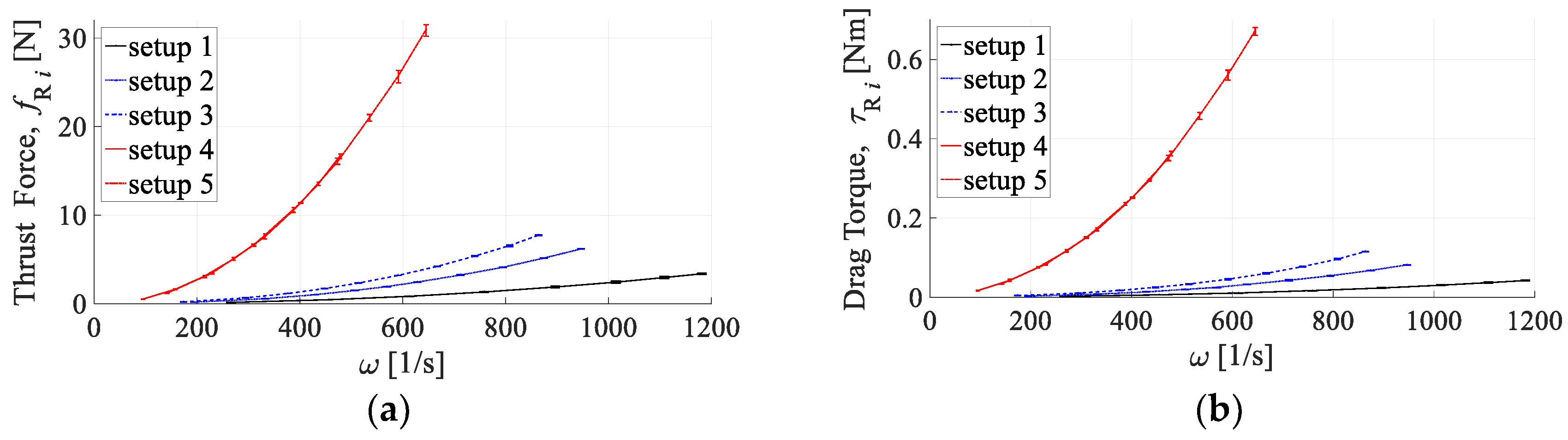
  27. Piljek, P.; Kotarski, D.; Krznar, M. Method for Characterization of a Multirotor UAV Electric Propulsion System. Appl. Sci. 2020, 10, 8229. [Google Scholar] [CrossRef]
  28. Kotarski, D.; Piljek, P.; Pranjić, M.; Grlj, C.G.; Kasać, J. A Modular Multirotor Unmanned Aerial Vehicle Design Approach for Development of an Engineering Education Platform. Sensors 2021, 21, 2737. [Google Scholar] [CrossRef] [PubMed]
  29. Fossen, T.I. Guidance and Control of Ocean Vehicles, 1st ed.; Wiley: Chichester, UK, 1994. [Google Scholar]
  30. Series 1580 Dynamometer Datasheet. Available online: https://cdn-docs.rcbenchmark.com/wp-content/uploads/2016/01/2016-02-04-RCbenchmark-1580-datasheet.pdf (accessed on 2 July 2021).
  31. Meier, L.; Honegger, D.; Pollefeys, M. PX4: A node-based multithreaded open source robotics framework for deeply embedded platforms. In Proceedings of the IEEE International Conference on Robotics and Automation (ICRA 2015), Seattle, WA, USA, 26–30 May 2015; pp. 6235–6240. [Google Scholar] [CrossRef]
  32. DJI Agras T20. Available online: https://www.dji.com/hr/t20 (accessed on 29 June 2021).
  33. Freefly Alta 8. Available online: https://freeflysystems.com/alta-8 (accessed on 29 June 2021).
  34. PC-1 Multipurpose Quadcopter. Available online: https://www.airforce-technology.com/projects/pc-1-multipurpose-quadcopter/ (accessed on 29 June 2021).
Figure 1. Generic conventional multirotor configurations.
Applsci 11 08786 g001
Figure 2. Schematic representation of the multirotor UAV configuration: (a) multirotor configuration (propulsion) reference coordinate systems; (b) schematic representation of the propulsion system.
Applsci 11 08786 g002
Figure 3. Schematic representation of PTX6 configuration maneuvering.
Applsci 11 08786 g003
Figure 4. EPU static maps: (a) thrust force; (b) drag torque.
Applsci 11 08786 g004
Figure 5. Aerodynamic effects with respect to rotor angular velocity: (a) thrust force; (b) drag torque.
Applsci 11 08786 g005
Figure 6. Simplified flow chart of the analysis procedure iterative algorithm.
Applsci 11 08786 g006
Figure 7. 3D cloud of points for propulsion forces margins.
Applsci 11 08786 g007
Figure 8. Propulsion force margins for PTX6 configuration consisting of EPUs setup 3.
Applsci 11 08786 g008
Figure 9. Propulsion forces margins for PTX8 configuration consisting of EPUs setup 5.
Applsci 11 08786 g009
Figure 10. System response of PTX6 functionality testing.
Applsci 11 08786 g010
Figure 11. PWM signals sent by FC aircraft in case of PTX6 functionality testing.
Applsci 11 08786 g011
Figure 12. Experimental testing of attitude control on PTX6 for the case of reference state tracking.
Applsci 11 08786 g012
Figure 13. Experimental results of PTX6 configuration response for attitude control.
Applsci 11 08786 g013
Figure 14. Experimental testing of remote control on PTX6.
Applsci 11 08786 g014
Table 1. Considered EPU setups.
SetupFixed-Pitch PropellerBLDC MotorESCEnergy Source
DiameterPitchDesignationKv
17″2.4″MN18061400Air 10 A12 V
29″4″MN2214920Afro 20 A12 V
310″4″MN2214920Afro 20 A12 V
417″6″MN4014400Air 40 A4S LiPo
517″6″MN4014400Air 40 A6S LiPo
Publisher’s Note: MDPI stays neutral with regard to jurisdictional claims in published maps and institutional affiliations.

