
Study on Ducted Vertical Take-Off and Landing Fixed-Wing UAV Dynamics Modeling and Transition Corridor


School of Aeronautics, Northwestern Polytechnical University, Xi’an 710072, China
*
Author to whom correspondence should be addressed.
Appl. Sci. 2021, 11(21), 10422; https://0-doi-org.brum.beds.ac.uk/10.3390/app112110422
Submission received: 7 October 2021
/
Revised: 29 October 2021
/
Accepted: 3 November 2021
/
Published: 5 November 2021
Abstract
:Featured Application
Authors are encouraged to provide a concise description of the specific application or a potential application of the work. This section is not mandatory.
Abstract
An accurate description of the transition corridor is of great significance for the flight process of the vertical take-off and landing (VTOL) fixed-wing unmanned aerial vehicle (UAV). To study the transition flight process of vertical take-off and landing fixed-wing UAVs, the dynamic model and transition corridor model of this type of UAV are established in the current article. The method for establishing the model is based on a reasonable match of the power and aerodynamic force of this type of UAV. From the perspective of flight dynamics, the ducted lift-increasing system’s deflection angle–speed envelope is studied with the maximum lift coefficient of the wing and the system’s available power. The influence of the overall parameters and energy parameters of the UAV on the deflection angle–speed envelope of the ducted lift-increasing system is analyzed, and a method is proposed to expand the vertical take-off and landing fixed-wing UAV’s transition corridor. Taking the UAV as the object, using the established model, the transition flight corridor of the UAV is obtained, the influence of the control parameters on the transition flight is studied, and the appropriate transition flight control strategy is determined. At the same time, the influence of the overall parameters and energy parameters on the transition corridor is calculated. According to the calculation results, the effect of expanding the flight corridor of the UAV is more obvious when increasing the available power than when increasing the aerodynamic parameters by the same proportion.
1. Introduction
The vertical take-off and landing fixed-wing UAV can achieve zero-speed take-off and landing without the need for a runway as in the case of the conventional aircraft. In the vertical take-off and landing mode, it is capable of hovering. In fixed-wing mode, high-speed and long-term flight can be achieved. It is one of the best choices to perform reconnaissance and monitoring tasks in special environments [1,2,3,4,5]. In this work, a ducted vertical take-off and landing fixed-wing UAV scheme is proposed. For this type of vertical take-off and landing fixed-wing UAV, the transition flight corridor (envelope) is studied.
There are many studies on the tilting corridor of the tilt-rotor vertical take-off and landing aircraft. Rajan Gill [6] studied a vertical take-off and landing unmanned aerial vehicle, presented with a quadrotor design for propulsion and attitude stabilization and an annular wing that provides lift in forward flight. Luz M. Sanchez-Rivera [7] focused on the Dual Tilt-Wing UAV, a vehicle capable of performing both flight modes (VTOL and CTOL). The complete dynamic model of a UAV was obtained using the Newton–Euler formulation, which includes aerodynamic effects as the drag and lift forces of the wings, which are a function of airstream generated by the rotors, cruise speed, tilt-wing angle, and angle of attack. The airstream velocity generated by the rotors was studied in a test bench. Seongwook Choi et al. [8] took the scaled-down prototype as the research object, then predicted the transition corridor of the tilt-rotor aircraft through blade element theory and momentum theory, and compared the nacelle inclination angle and flight speed envelope with experimental test results. After a series of flight tests, they determined the transition from helicopter mode to fixed-wing mode. Sergio Garcia-Nieto [9] studied unmanned aerial vehicles operating in this configuration, which were also categorized as hybrid UAVs due to dual flight envelope—hovering like a multi-rotor and cruising like a traditional fixed-wing, the two different dynamics enable UAVs to carry out complex missions. Siddhant Panigrahi et al. [10] discussed the overall conceptual design, dynamic modeling, computational simulation, and experimental analysis of the novel hybrid fixed-wing bicopter with thrust vectoring capabilities, with the aim of substantially increasing the flight range and endurance compared to conventional aircraft rotorcraft configurations. Cao Yunyun [11,12] proposed a power system of the tilt angle–speed envelope of the transitional flight from vertical take-off and landing to horizontal flight for this kind of aircraft. The envelope analysis method was studied from the two aspects of low speed and high speed, the matching relationship of each power in the transition process was analyzed, and the tilt–speed envelope of the wing stall limit was determined. Wan Huafang [13] aimed to determine the range of values of the attitude angle of the tilt-rotor aircraft during flight trim. Taking the XV-15 aircraft as an example, the transition corridor was calculated and determined, and a transition route was found within the envelope of the transition corridor, for which the trim attitude angle of the XV-15 was the smallest during the transition flight. Chen Yong et al. [14] aimed at studying the complex control characteristics of the tilt-rotor aircraft with both vector dynamic control and aerodynamic rudder surfaces. The transitional states were balanced and trimmed, the control quantities of each state were calculated, and the transition corridor was designed. Zhu Han et al. [15] established the aerodynamic model of the body parts for high-speed helicopters with fixed wings. Furthermore, a full dynamics model of the entire machine was established, and on this basis, the state point analysis method was used to determine the safe transition corridor of the high-speed helicopter. With the analysis of the model, different flight speeds and pitch angles were obtained, and the transition flight corridor of the high-speed helicopter was obtained by combining the state variables. Duan Saiyu et al. [16] established a mathematical model of the flight dynamics of a compound coaxial helicopter. Taking a small coaxial fixed-wing helicopter as an example, the Newton iteration method was used to complete the trimming of the attitude and control quantity at different flight speeds, and the preliminary calculation method was given for the transition flight corridor.
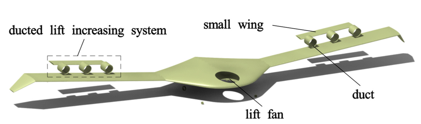
The above works mainly focused on the transitional flight corridors of tilt-rotor aircraft and purely ducted aircraft. However, there is little work on the transition corridor of vertical take-off and landing fixed-wing UAVs powered by ducts and lift fans. In this work, a ducted vertical take-off and landing fixed-wing UAV is taken as the research object. The UAV power system is divided into two parts: one is the front lift fan system, and the other is the ducted lift-increasing system composed of the duct and the small wing surface (see Figure 1). The lift fan system is a coaxial rotor system that includes an upper rotor and a lower rotor, and the upper and lower rotor moments cancel each other out. The UAV of this configuration can achieve vertical take-off and landing, as well as the high speed and long endurance of the fixed-wing aircraft. The objectives of this work are to establish a transition corridor model of this type of UAV, to find its flight boundary, and to propose a method to expand the flight corridor. Based on the matching of UAV power and aerodynamic balance, a vertical take-off and landing fixed-wing UAV transition flight corridor is established from the perspective of flight dynamics. The left boundary of the transition corridor is determined by the maximum lift coefficient. The right boundary of the corridor is determined by the UAV’s available power. Finally, the UAV is calculated for the transition corridor. Then, the flight envelope of the vertical take-off and landing fixed-wing UAV is analyzed based on overall parameters, and a method is provided for the design of the transitional corridor of the vertical take-off and landing fixed-wing UAV.
2. UAV Dynamic Model
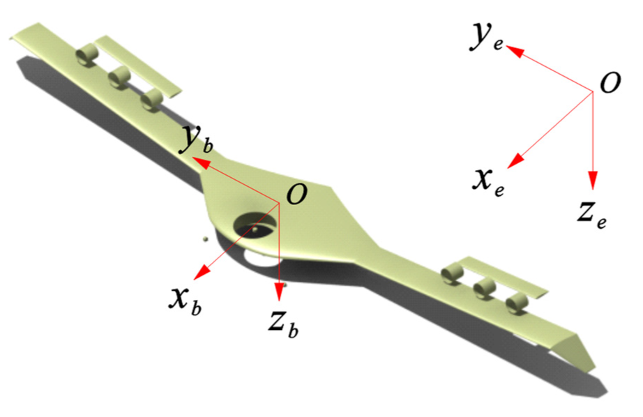
Aerodynamic modeling of the UAV adopts the airframe axis coordinate system and the earth axis system (see in Figure 2). The origin of the axis system is at the center of gravity of the UAV. The x-axis points forward along the plane of symmetry of the fuselage. The y-axis is perpendicular to the x-axis. The z-axis is determined by the right-hand rule. The x-axis and z-axis constitute the symmetry of the fuselage. Modeling of the lift fan and duct is based on the self-body axis system, which is an independent system of the lift fan and duct.
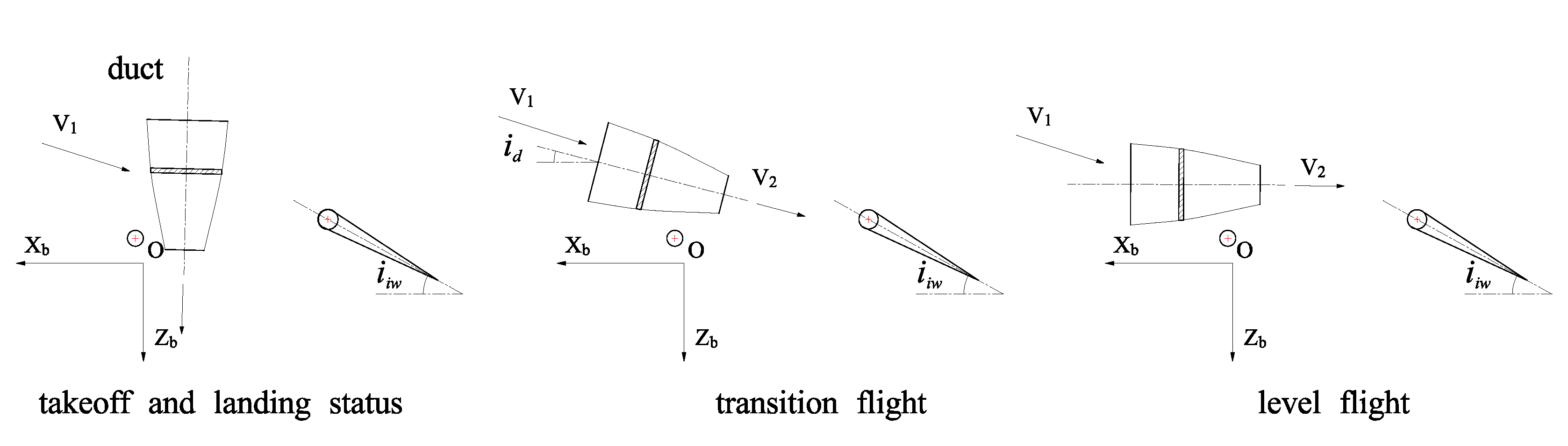
The process of UAV take-off and transition to level flight is shown in Figure 3. During vertical take-off and landing, the duct deflects to provide upward thrust, and the lift fan in front also generates upward thrust. In the transition process, the forward-flying thrust is obtained by deflecting the duct inclination, and the transition from vertical take-off to horizontal flight is completed under certain control strategies. In level flight, the duct is deflected to the horizontal position, and the flight is controlled by the deflection of the control surface.
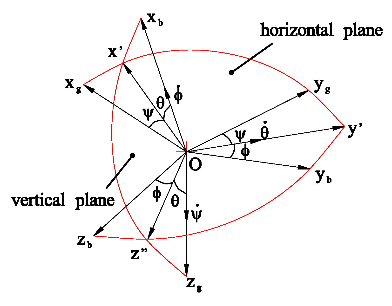
In the process of modeling the vertical take-off and landing UAV, the coordinate system and angle need to be defined. Fang Zhenping [17] studied the coordinate system and the conversion relationship, and the Euler transformation relationship between the ground coordinate system and the airframe coordinate system (see in Figure 4) is used in this article. Yaw angle : the angle between the projection of the body axis on the horizontal plane and the axis. The angle is positive when the aircraft yaws right. Pitch angle : the angle between the body axis and the horizontal plane . When the head of the aircraft is raised, the angle is positive. Roll angle : the angle between the plane of symmetry of the aircraft and the vertical plane containing the axis. The angle is positive when the aircraft rolls right.
According to the general law of coordinate transformation, the transformation matrix from the earth coordinate system to the body coordinate system can be obtained as
We project the aerodynamic forces and aerodynamic moments of the lift fan and ducted lift-increasing system, and combine the control equations to obtain the nonlinear flight dynamics mathematical equations of the vertical take-off and landing fixed-wing UAV. The mathematical model of nonlinear flight dynamics can generally be written in the form of a first-order differential equation:
where y represents all of the state quantities of the vertical take-off and landing fixed-wing UAV flight dynamics equation, and u represents the control quantities of the vertical take-off and landing fixed-wing UAV, and they are defined as
The force and moment of the body expressed by the state quantity of the dynamic equation, that is, the reference motion parameter y used in the equation, are as follows:
It can be seen in the body axis formation process that is formed by the angular velocity along the axis; is formed by the angular velocity along the axis, which is projected along the body axis as ; is formed by the angular velocity along the axis. It can be concluded that the projection of the rotational angular velocity on the shaft system of the body is
The solution result is a dynamic equation rotating around the center of mass, expressed as
The above Formulas (4), (5) and (7) are the dynamic model of the vertical take-off and landing fixed-wing UAV.
3. UAV Transition Corridor
In the vertical take-off and landing fixed-wing UAV, its power configuration is quite different from that of a helicopter. It is mainly composed of a front lift fan and a rear ducted lift-increasing system. In fixed-wing flight mode, the front lift fan turns off, and the ducted lift-increasing system deflects to level. The duct is used as the propulsion power, and the wing is the lift surface. During the transitional flight, the ducted lift-increasing system keeps deflecting, and the power of the lift fan keeps changing. When the UAV is flying at low speed, a faster deflection of the ducted lift-increasing system may cause the wing to stall and fail to complete the transition. When the flying speed of the UAV is too high, the deflection of the ducted lift-increasing system may cause problems such as insufficient available power. The ducted lift-increasing system’s deflection angle–speed envelopes studied in this paper are carried out at low and high speeds. The low-speed section is the left boundary of the flight transition corridor, while the high-speed section is the right boundary.
3.1. Transition Window
The flight transition window refers to the collection of parameters of the external conditions and the aircraft’s own conditions required to complete a certain flight task [18]. The transition flight window in this article can be divided into the transition beginning window and the transition ending window. The resultant force parameter matching between the beginning window and the ending window can form the transition flight corridor. The transition beginning window is the flight state hovering at a safe altitude after vertical take-off; the transition ending window is the flight state meeting the safe level flight speed. The transition beginning window usually meets a certain safety height. In this paper, based on the experience of helicopters, this height is set as 20 m. The transition ending window usually has three important flight parameters, namely, flight speed, power thrust, and attitude of the UAV, which can be calculated via Formula (8)–(10):
where G is the weight of the UAV; L is the aerodynamic lift; is the air density; is the stall speed of the UAV; S is the wing area; is the maximum lift coefficient of the UAV; is the safe flight speed of the terminal window; and M is the torque. For the equilibrium equation, see Formula (11):
Where is the thrust of lift fan; is the thrust of the ducted lift-increasing system; is the pitch angle of the aircraft; is the deflection angle of the ducted force; is the lift fan lever; is the increased lift ducted lever.
3.2. Ducted Lift-Increasing System’s Deflection Angle–Speed Envelope Based on Stall Angle of Attack
The transition corridor in the low-speed section starts from the hovering state until the ducted lift-increasing system deflects to the fixed-wing flight mode. At this time, the angle of attack is the stall angle of attack. When hovering, the aerodynamic force of the ducted lift-increasing system and the aerodynamic force of the front lift fan balance the gravity of the UAV. Under normal circumstances, the attitude angle of the UAV is zero. At this time, the lift fan pull and ducted lift-increasing system’s aerodynamic force are vertically upward. Due to the existence of the small wing, the deflection angle of the rising duct is generally less than 90 degrees. The aerodynamic deflection angle of the ducted lift-increasing system is related to the deflection angle of the duct and the deflection angle of the small wing, which can be expressed as
where is the resultant deflection angle of the ducted lift-increasing system, is the deflection angle of the duct relative to the airframe, and is the deflection angle of the ducted lift-increasing system relative to the small wing.
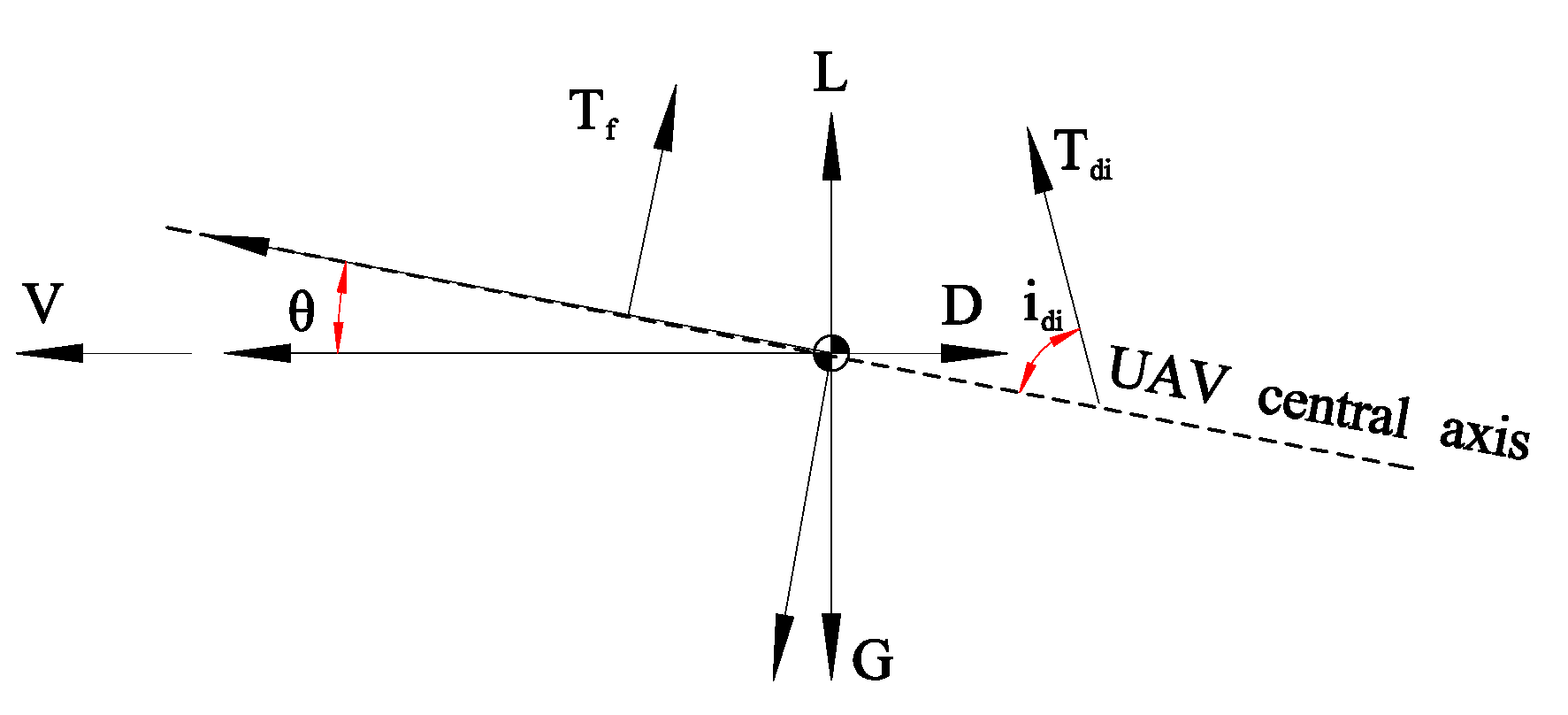
Figure 5 shows the force diagram of the UAV during the transition flight. In this diagram, is the fuselage angle of attack, and L and D are the wing aerodynamic lift and drag respectively, which include the aerodynamic force of the main wing’s free flow and the main wing-induced aerodynamic force. According to the force of the UAV, the balance relationship can be analyzed as follows:
where lift and drag can be expressed as
where subscript “A” represents all aerodynamic forces, including free-flow aerodynamic forces and induced aerodynamic forces on the main wing caused by duct inlet airflow. and in the formula are the induced lift and induced drag of the duct on the main wing, and the subscript “mw” represents the main wing-induced force.
During the transition of a vertical take-off and landing fixed-wing UAV, the gravity of the UAV is mainly balanced by the lift fan and the ducted lift-increasing system to transition to aerodynamic balance. Early transition flight speed is low, and the wing provides a lift limitation to the critical stall angle of attack. When calculating the envelope of the transition low-speed section, the maximum angle of attack is taken as the critical angle of attack, and the maximum angle of attack in the low-speed section of the transition flight envelope satisfies the following relationship:
where is the critical angle of attack of the wing and is the wing installation angle.
3.3. Deflection Angle–Speed Envelope Based on Power Limit in Ducted Lift-Increasing System
The envelope of the equilibrium state gives the deflection angle–speed envelope of the ducted lift-increasing system on the premise that the wing does not stall. However, in actual flight, as long as the power is sufficient, the UAV can complete transition well even if the wing is stalled. In this section, the deflection angle–velocity envelope of the ducted lift-increasing system is determined according to the available power of the ducted lift-increasing system as a constraint [19].
The ducted lift-increasing system must satisfy the balance of the lift fan and ducted lift-increasing system aerodynamic force and the airframe aerodynamic force with the gravity of the UAV during the deflection process, and the available power of the lift fan and ducted lift-increasing system are required during the transitional flight.
The required power of the lift fan and the duct is the same, which is composed of the induced power , type resistance power , waste resistance power , and climbing power .
where is the transmission loss coefficient from the engine to the blades.
According to the conservation of energy and momentum theorem, the expressions of the waste resistance power , induced power and climb power can be expressed as follows:
where is the vertical velocity of the blade plane and is the induced velocity of the rotor blade.
Considering the existence of multi-blade blades in the lift fan and duct, the induced speed is non-uniform. In this paper, the induced speed is modified by , and the above formula becomes
According to the blade element theory, the rotor-type resistance power can be expressed as
where , is the solidity of the rotor, is the drag coefficient of the blade, is the tip speed of the rotor, and is the forward ratio. For lift fans and duct power components, their power can be obtained by the above formula [12].
Thus, in the case of the power limitation, the VTOL fixed-wing UAV’s angle–speed envelope boundary must satisfy the force balance, and, at the same time, the total power of the lift fan and duct must be less than the available power of the system , i.e., .
3.4. Transition Corridor Calculation
The transition corridor is the transition flight envelope. Equation (13) is the balance equation that is used to calculate the vertical take-off and landing transition corridor of the fixed-wing UAV. Equations (8) and (13) can be combined to solve three unknowns, namely, the thrust of the lift fan , the thrust of the ducted lift-increasing system , and the thrust deflection angle of the ducted lift-increasing system . When calculating the deflection angle of the ducted lift-increasing system based on the stall speed, the thrust of the lift fan, the thrust of the ducted lift-increasing system, and the thrust deflection angle of the ducted lift-increasing system are used as the solution. When calculating the deflection angle of the ducted lift-increasing system based on the power, the power of the lift fan and the duct are limited, and the attitude of the UAV is used as the solution.
Firstly, the power parameters of the beginning window of the transition flight envelope are determined by the hovering state Formula (11). The UAV aerodynamic coefficients and at different flight speeds are calculated according to Formula (8). The above calculation results are substituted into Formula (14) to calculate the aerodynamic force of the UAV, and the final aerodynamic result is substituted into the balance Formula (13). Using the lift fan force , ducted lift-increasing system force , and force deflection angle as solution quantities for the trim calculation, the deflection angle–velocity envelope of the ducted lift-increasing system based on stall speed can be obtained. When calculating the deflection angle–speed envelope of the ducted lift-increasing system based on power, given the deflection angle value of the ducted lift-increasing system, the required power of the component is calculated according to the power formula, and, finally, the power-based transition flight envelope of the vertical take-off and landing fixed-wing UAV is obtained according to the output power limitation of the power components.
4. Results and Discussion
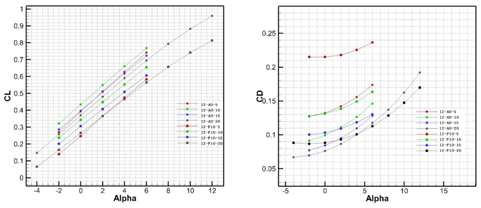
Taking a certain type of vertical take-off and landing fixed-wing UAV as a case prototype, the ducted lift-increasing system’s deflection angle–speed envelope during the transition flight is calculated [20]. Wang C et al. [20] studied the dynamic modeling and transitional flight strategy of this type of aircraft but did not study its transitional flight corridor. The calculation of the transitional flight corridor is studied in detail below. Figure 6 shows the relationship between the lift coefficient and drag coefficient of the prototype during transitional flight with the angle of attack. In the legend, “12-A0-5” means that the ducted lift-increasing system has a single ducted power of 12N, the angle of attack is 0°, and the free flow is 5 m/s. The aerodynamic data at specific state points in the transition process are calculated based on the aerodynamic coefficient curve. The rated power and calculation parameters of the lift fan and ducted lift-increasing system are shown in Table 1.
4.1. Calculation Results
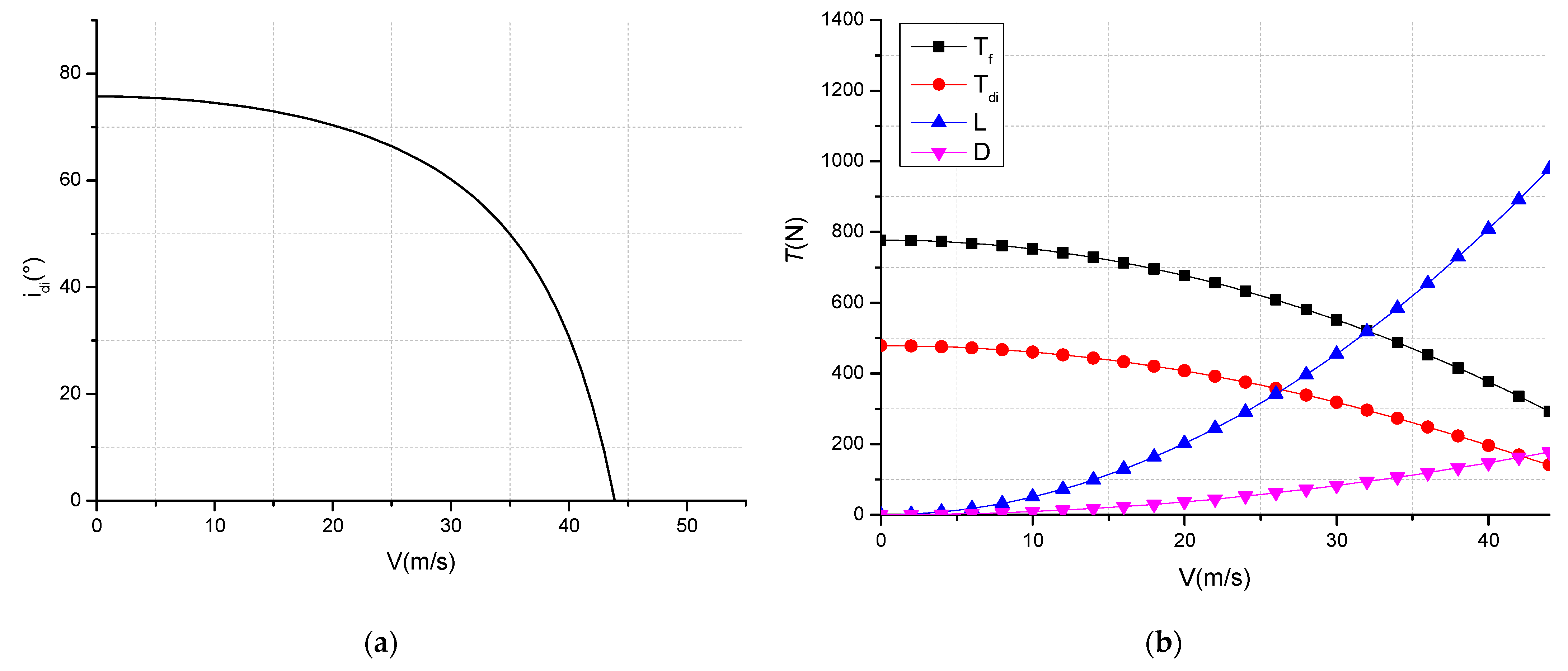
In Figure 7a, declination angle–speed envelope of the UAV ducted lift-increasing system is calculated based on the case of the stall angle of attack. It can be seen that in the hover phase, the force deflection angle of the ducted lift-increasing system is 75 degrees, and the minimum flight speed when deflected to the fixed-wing flight mode is 43 m/s. Figure 7b shows the curve of lift fan thrust, the thrust of the ducted lift-increasing system, and body lift and drag in the transitional flight envelope. It can be seen that when hovering, the gravity of the UAV is balanced by the pull force of the lift fan and the ducted lift-increasing system. With the deflection of the ducted lift-increasing system, the lift of the UAV is provided by the power components and gradually transitions to the wings. As speed increases, the lift and drag of the UAV also increase.
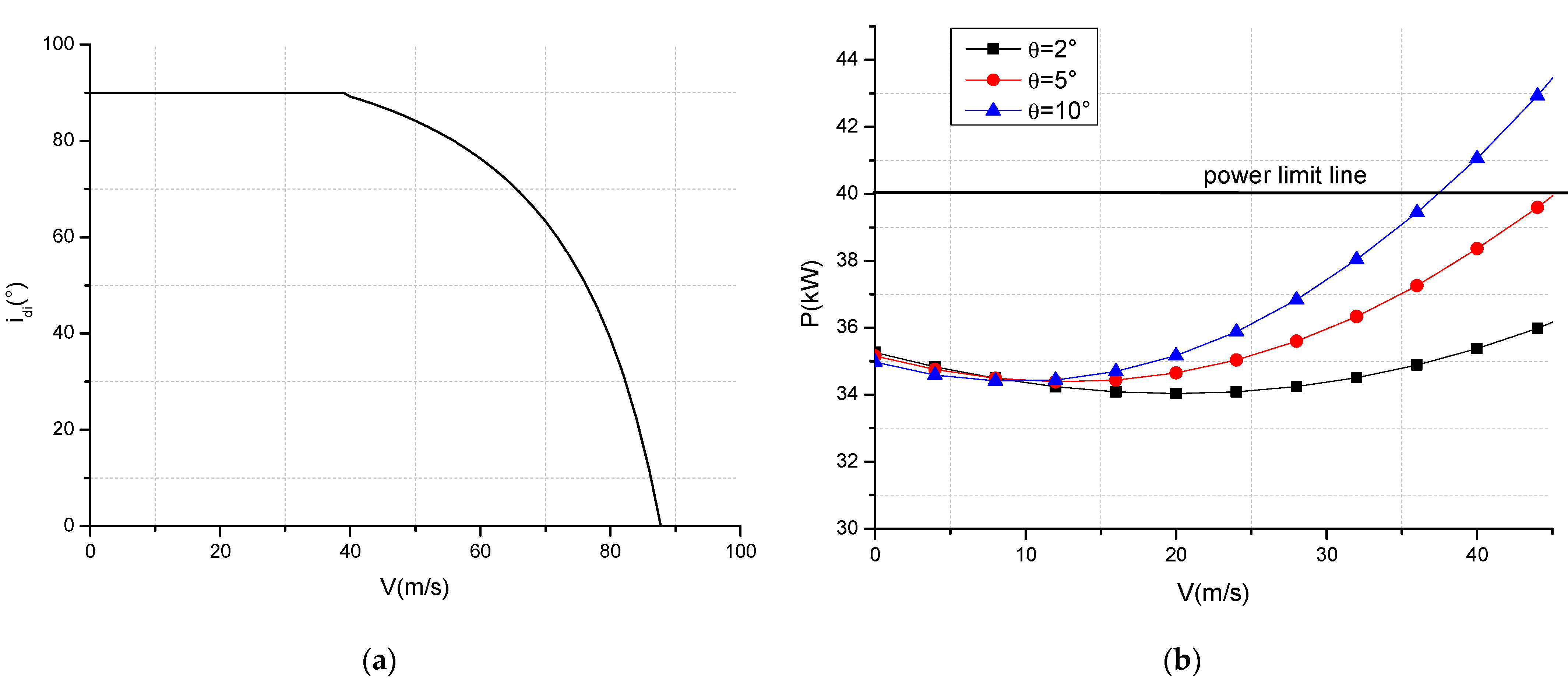
Figure 8a is given based on a power limit of the deflection angle–speed envelope of the ducted lift-increasing system. The results in this figure differ from those shown in Figure 7a in that in the high-speed range, the perpendicular angle of the ducted force may be maintained until the trigger power limit. Figure 8b shows the curve of the power of the UAV’s power components with the flight speed during the transition process under different attitude angles. Under the condition of power limitation, if the required power and the maximum available power are equal, a power-based deflection angle–speed envelope of the vertical take-off and landing fixed-wing UAV’s ducted lift-increasing system can be obtained. It can be seen that with the increase in speed at the same attitude angle, the required power first decreases and then increases, which is closely related to the inflow characteristics of the duct. At the same time, it can be seen from the three curves with different attitude angles that the transition power at a large attitude angle is greater than that at a low angle of attack. The large attitude angle transition will trigger the power limit at low speed, because the higher the attitude angle is, the greater the resistance during the transition and the greater the required power.
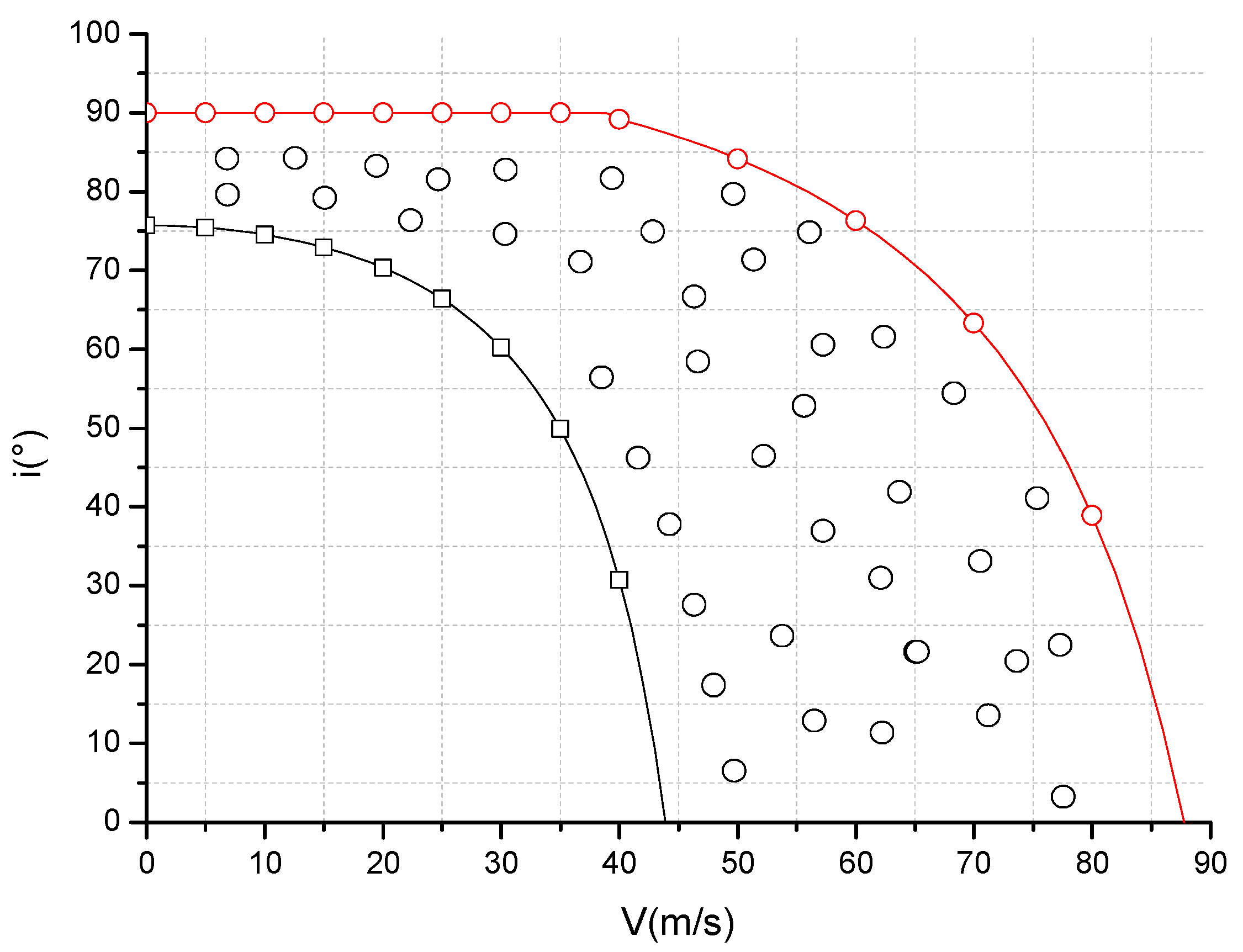
Combining the flight envelope calculated based on the stall angle of attack and the flight envelope calculated based on the power limit, the transition flight corridor of the vertical take-off and landing fixed-wing UAV can be obtained (see in Figure 9). It can be seen that the left boundary of the transition corridor in the low-speed section is the deflection angle–speed envelope of the ducted lift-increasing system based on the stall angle of attack, and the right boundary of the high-speed section is the power-based deflection angle–speed envelope of the ducted lift-increasing system. The UAV can complete the transition flight in the transition corridor between the two envelopes.
4.2. Influence Analysis of the Manipulation Parameter
The transitional flight process of the vertical take-off and landing fixed-wing UAV is the intermediate process connecting the vertical take-off and landing fixed-wing flight process, and it is an important flight mode of the vertical take-off and landing fixed-wing UAV. During the transition flight, the ducted lift-increasing system deflects continuously, the aerodynamic configuration changes accordingly, and the aerodynamic force also changes accordingly. Transition flight is also a dangerous flight mode. The larger the declination angle–speed envelope of the vertical take-off and landing fixed-wing UAV’s ducted lift-increasing system, the easier it is to achieve the transitional flight process. Within the flight envelope, the flight attitude of the UAV and the speed of power deflection have a certain impact on the transition process.
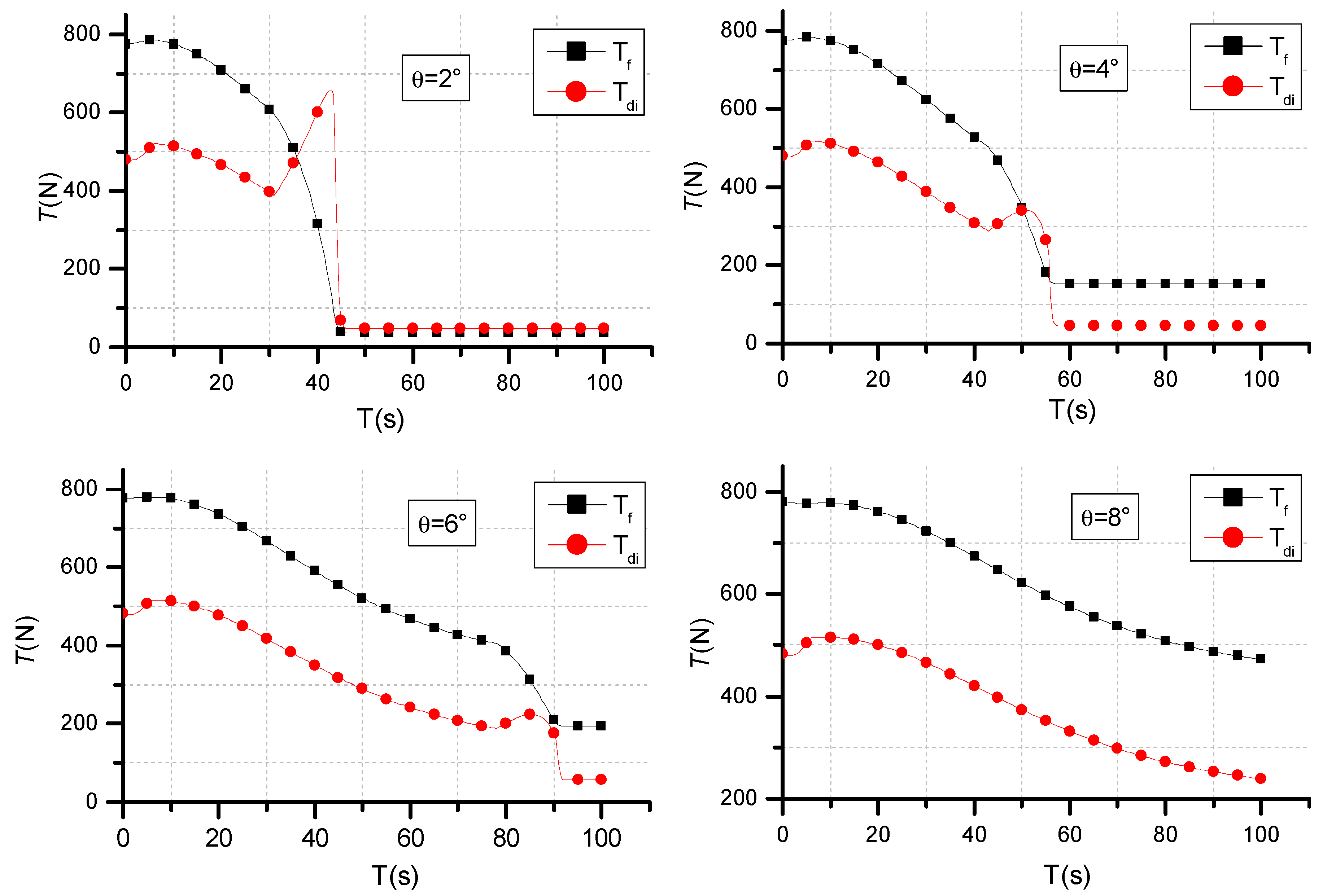
In the transition process, on the premise of ensuring longitudinal balance, the transition at different pitch angles will have different transition state characteristics (see in Figure 10 and Figure 11). From the calculation of flight data, it can be seen that in the ducted deflection data, when transitioning at a large attitude angle, the duct deflection can be completed at a lower flight speed, while for transition flight at a small attitude angle, a higher flight speed is required, as it allows for the flight transition to be completed.
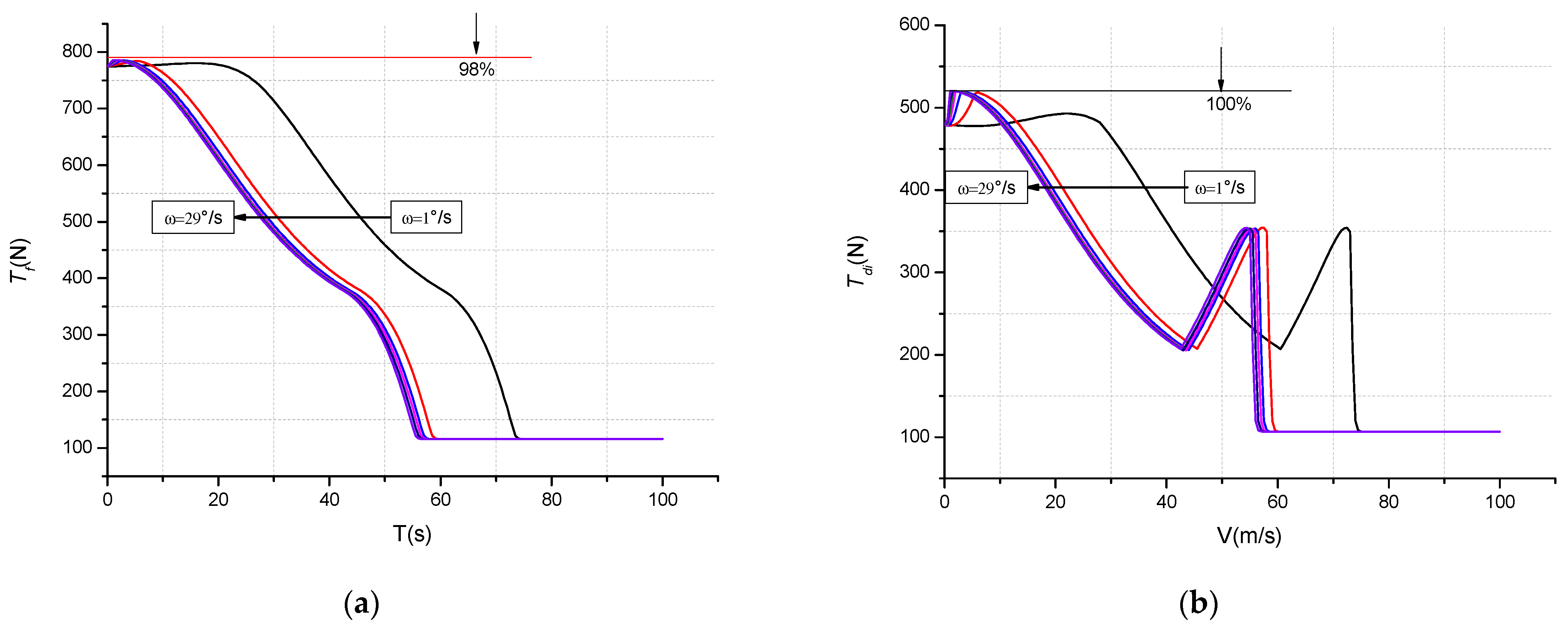
When deflection rates of the duct are different, fixed-wing vertical take-off and landing UAVs have different trim-flying capabilities. Within the allowable range of the power system, the deflection rate of the duct can vary from 1°/s to 29°/s (see in Figure 12). When the deflection rate of the duct exceeds 29°/s, transition flight will exceed the lift fan trim capability of the aircraft, and, therefore, it cannot be completed.
The simulation result is calculated under the stable equilibrium state of the UAV. In this state, it is found that when the transition time is the target, the smaller the pitch attitude angle, the faster the completion time of the transition flight. Taking the dynamic characteristics of the power system as the target, it is found that the transition flight can be completed stably when the pitch angle is 3°, the duct deflection rate is 5°/s, and the deflection rate of the small wing surface is 1.5°/s.
4.3. Influence Analysis of the Overall Parameter
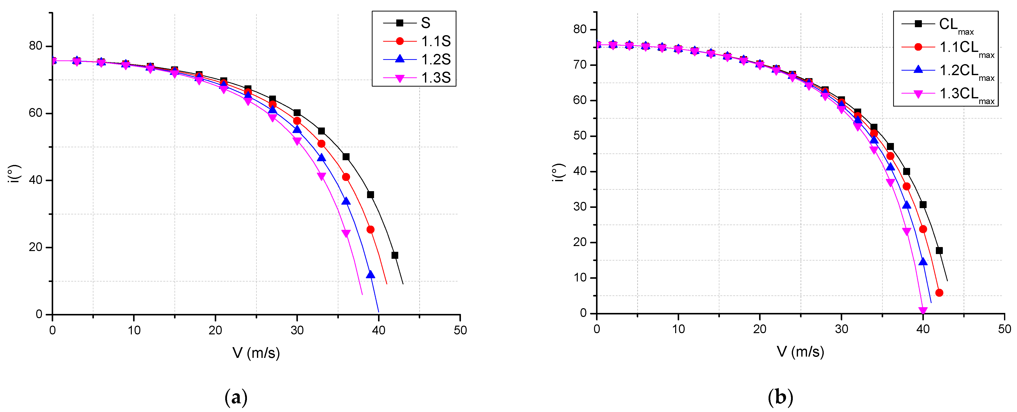
In aircraft design, the way in which the overall parameters of the vertical take-off and landing fixed-wing UAV affect the flight envelope is straightforward. In this work, the flight envelope of the vertical take-off and landing fixed-wing UAV is analyzed from the perspective of overall parameters, and a method for the design of the transitional corridor of the vertical take-off and landing fixed-wing UAV is proposed. The deflection angle–speed envelope of the ducted lift-increasing system based on the stall angle of attack is calculated with the maximum lift coefficient, and the stall angle of attack of the wing is mainly affected by the wing area, the wing lift coefficient, and the wing installation. Therefore, the deflection angle–speed envelope of the ducted lift-increasing system based on the stall angle of attack is affected by these parameters. Figure 13a shows the ducted lift-increasing system’s deflection angle–velocity envelope based on the stall angle of attack after the wing area increased by 10%, 20%, and 30%, and Figure 13b shows the deflection angle–speed envelope of the ducted lift-increasing system’s variation diagram based on the stall angle of attack after the maximum lift coefficient increased by 10%, 20%, and 30%. It can be seen that changing the wing area and changing the maximum stall lift coefficient can change the position of the deflection angle–speed envelope of the ducted lift-increasing system based on the stall angle of attack. The flight envelope moves to the left when increasing the wing area and increasing the maximum stall lift coefficient, and the flight envelopes expand by 4.6%, 6.9%, and 11.6%.
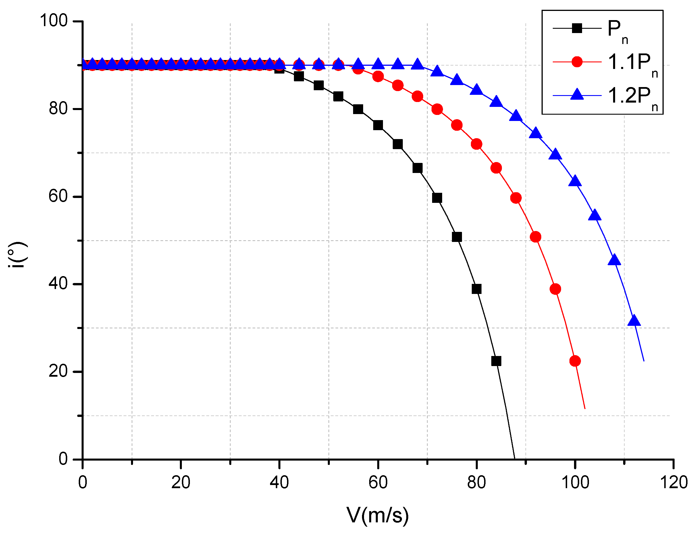
The right boundary of the flight corridor of the vertical take-off and landing fixed-wing UAV is determined by the deflection angle–speed envelope of the power-based ducted lift-increasing system, thus reducing the required power of the flight state or increasing the available power of the flight system. It is possible to change the deflection angle–speed envelope of the ducted lift-increasing system. Figure 14 shows the deflection angle–speed envelope of the ducted lift-increasing system based on power after increasing the available power by 10% and 20%. It can be seen that as the available power increases, the power-based ducted lift-increasing system’s deflection angle–speed envelope moves to the right, thus expanding the flight corridor boundary. It is calculated that the flight envelope expands by 21% and 40%. As shown in Figure 13 and Figure 14, the effect of using the improvement in the overall parameters to expand the flight corridor is worse than using available power to expand the flight corridor under the same percentage. That is, the effect of using energy to expand the flight corridor is more significant than using the overall parameters. As the effect of the power parameters increased by 10% and that of the aerodynamic parameters also increased by 10%, it can be observed that increasing the power can enlarge the transition corridor by 21%, while increasing the aerodynamic parameters can only expand the transition corridor by 4.6%.
5. Conclusions
(1) The model proposed in this article can describe the transitional flight corridor of a vertical take-off and landing fixed-wing UAV;
(2) The left boundary of the transition flight corridor of this type of vertical take-off and landing fixed-wing UAV is determined by the maximum lift coefficient during the transition flight, and the right boundary is determined by the maximum available power;
(3) In the process of transition flight, the transition completion time with a small attitude angle is the shortest, while the transition power deflection at a large attitude angle is slower, and the completion process is stable.
(4) Enlarging the transition corridor of this type of UAV through the design of overall parameters, the results show that the improvement in the transition corridor by increasing the available power is more obvious than that when increasing the aerodynamic parameter in the same proportion.
Author Contributions
Conceptualization, Z.Z. and C.W.; methodology, C.W.; validation, R.W.; formal analysis, C.W.; investigation, R.W.; resources, Z.Z.; data curation, C.W.; writing—original draft preparation, C.W.; writing—review and editing, C.W.; supervision, R.W. and Y.D.; project administration, Z.Z. All authors have read and agreed to the published version of the manuscript.
Funding
This research was funded by Innovative Plan of the Compound, grant number TC2018DYDS24.
Institutional Review Board Statement
Not applicable.
Informed Consent Statement
Not applicable.
Conflicts of Interest
The authors declare no conflict of interest.
References
- Kanistras, K.; Martins, G.; Rutherford, M.J.; Valavanis, K.P. A Survey of Unmanned Aerial Vehicles (UAVs) for Traffic Monitoring; Springer: Dordrecht, The Netherlands, 2015. [Google Scholar]
- Michael, N.; Mellinger, D.; Lindsey, Q.; Kumar, V. The GRASP Multiple Micro-UAV Testbed. IEEE Robot. Autom. Mag. 2010, 17, 56–65. [Google Scholar]
- Zheng, Z. Research on Overall Design Method of Lift Fan Vertical Take-Off and Landing Aircraft. Ph.D. Thesis, Northwestern Polytechnical University, Xi’an, China, 2013. [Google Scholar]
- Li, L. Development History of Helicopters; Aviation Industry Press: Beijing, China, 2007. [Google Scholar]
- Li, J. The technical characteristics and operational use of shipborne UAVs. Mod. Mil. 2002, 7, 33–35. [Google Scholar]
- Gill, R.; D’Andrea, R. An Annular Wing VTOL UAV: Flight Dynamics and Control. Drones 2020, 4, 14. [Google Scholar] [CrossRef]
- Sanchez-Rivera, L.M.; Lozano, R.; Arias-Montano, A. Development, Modeling and Control of a Dual Tilt-Wing UAV in Vertical Flight. Drones 2020, 4, 71. [Google Scholar] [CrossRef]
- Choi, S.W.; Kang, Y.; Chang, S.; Koo, S.; Kim, J.M. Development and Conversion Flight Test of a Small Tiltrotor Unmanned Aerial Vehicle. J. Aircr. 2012, 47, 730–732. [Google Scholar] [CrossRef]
- Garcia-Nieto, S.; Velasco-Carrau, J.; Paredes-Valles, F.; Salcedo, J.V.; Simarro, R. Motion Equations and Attitude Control in the Vertical Flight of a VTOL Bi-Rotor UAV. Electronics 2019, 8, 208. [Google Scholar] [CrossRef] [Green Version]
- Panigrahi, S.; Krishna, Y.S.S.; Thondiyath, A. Design, Analysis, and Testing of a Hybrid VTOL Tilt-Rotor UAV for Increased Endurance. Sensors 2021, 21, 5987. [Google Scholar] [CrossRef] [PubMed]
- Cao, Y.; Chen, R. Investigation on nacelle conversion envelope analysis methodof tiltrotor aircraft. J. Aerosp. Power 2011, 26, 2174–2180. [Google Scholar]
- Cao, Y. Research on Mathematical Modeling Method for Tilt Rotor Aircraft Flight Dynamics. Ph.D. Thesis, Nanjing University of Aeronautics and Astronautics, Nanjing, China, 2013. [Google Scholar]
- Wan, H. Simulation Research on Transition Section of Tilt-Rotor Vehicle. Ph.D. Thesis, Nanjing University of Aeronautics and Astronautics, Nanjing, China, 2011. [Google Scholar]
- Chen, Y.; Gong, H.; Wang, B. Research on Longitudinal Attitude Control Technology of Transition Section of Tilt-rotor Aircraft. Flight Mech. 2011, 29, 30–33. [Google Scholar]
- Zhu, H.; Dong, R.; Jiang, S. Research of Composite High-speed Helicopter Transition Corridor and Optimal Transition Route. Mach. Build. Autom. 2021, 1, 188–192. [Google Scholar]
- Duan, S.; Chen, M. Research on Mathematical Model of Hybrid Coaxial Helicopter Flight Dynamics. Aircr. Des. 2011, 31, 13–17. [Google Scholar]
- Fang, Z. Aerocraft Flight Dynamics; Beihang University Press: Beijing, China, 2005. [Google Scholar]
- Wang, C.; Zhou, Z.; Wang, R.; Wang, K. Study on the longitudinal stability of ducted vertical take-off and landing fixed-wing UAV. J. Northwest. Polytech. Univ. 2021, 39, 712–720. [Google Scholar] [CrossRef]
- Pan, Z. Research on Calculation Method of Tilting Transition Corridor of Tilting Quadrotor. Ph.D. Thesis, Nanjing University of Aeronautics and Astronautics, Nanjing, China, 2019. [Google Scholar]
- Wang, C.; Zhou, Z.; Wang, R.; Zhou, W. Research on Dynamic Modeling and Transition Flight Strategy of VTOL UAV. Appl. Sci. 2019, 9, 4937. [Google Scholar] [CrossRef] [Green Version]
Figure 1.
Conceptual graphs of vertical take-off and landing fixed-wing UAV, which includes a lift fan and ducted lift-increasing system.
Figure 1.
Conceptual graphs of vertical take-off and landing fixed-wing UAV, which includes a lift fan and ducted lift-increasing system.

Figure 2.
Bod y-axis coordinate system and earth axis coordinate system.

Figure 3.
Duct deflection in three flight states.

Figure 4.
Relationship between the ground coordinate system and the airframe coordinate system.

Figure 5.
Schematic graph of force during transition flight.

Figure 6.
UAV lift and drag coefficient schematic diagram of force during transition flight.

Figure 7.
The calculation result of the transition corridor based on the maximum lift coefficient. (a) Deflection angle of ducted lift-increasing system force. (b) Power and lift and drag curve.
Figure 7.
The calculation result of the transition corridor based on the maximum lift coefficient. (a) Deflection angle of ducted lift-increasing system force. (b) Power and lift and drag curve.

Figure 8.
Results of the calculation of the transition corridor calculation based on power limitation. (a) Deflection angle of ducted lift-increasing system’s force. (b) Power curves of different attitude angle.
Figure 8.
Results of the calculation of the transition corridor calculation based on power limitation. (a) Deflection angle of ducted lift-increasing system’s force. (b) Power curves of different attitude angle.

Figure 9.
UAV transition corridor.

Figure 10.
Flight data at different pitch angles.

Figure 11.
Power data corresponding to different pitch angles.

Figure 12.
The influence of different deflection speeds on power. (a) Pull-force change curve of lift fan; (b) pull-force change curve of ducted lift-increasing system.
Figure 12.
The influence of different deflection speeds on power. (a) Pull-force change curve of lift fan; (b) pull-force change curve of ducted lift-increasing system.

Figure 13.
The influence of aerodynamic parameters on the flight corridor. (a) Influence curve of wing area; (b) influence curve of maximum lift coefficient.
Figure 13.
The influence of aerodynamic parameters on the flight corridor. (a) Influence curve of wing area; (b) influence curve of maximum lift coefficient.

Figure 14.
The influence of available power on flight corridors.


Table 1.
Calculation parameters and empirical coefficients.
| Parameter | Value | Parameter | Value | Parameter | Value |
|---|---|---|---|---|---|
| /° | 0–30 | /kW | 26 | 0.95 | |
| /° | 0–95 | /kW | 14 |
Publisher’s Note: MDPI stays neutral with regard to jurisdictional claims in published maps and institutional affiliations. |
© 2021 by the authors. Licensee MDPI, Basel, Switzerland. This article is an open access article distributed under the terms and conditions of the Creative Commons Attribution (CC BY) license (https://creativecommons.org/licenses/by/4.0/).
Share and Cite
MDPI and ACS Style
Wang, C.; Zhou, Z.; Wang, R.; Ding, Y. Study on Ducted Vertical Take-Off and Landing Fixed-Wing UAV Dynamics Modeling and Transition Corridor. Appl. Sci. 2021, 11, 10422. https://0-doi-org.brum.beds.ac.uk/10.3390/app112110422
AMA Style
Wang C, Zhou Z, Wang R, Ding Y. Study on Ducted Vertical Take-Off and Landing Fixed-Wing UAV Dynamics Modeling and Transition Corridor. Applied Sciences. 2021; 11(21):10422. https://0-doi-org.brum.beds.ac.uk/10.3390/app112110422
Chicago/Turabian StyleWang, Chunyang, Zhou Zhou, Rui Wang, and You Ding. 2021. "Study on Ducted Vertical Take-Off and Landing Fixed-Wing UAV Dynamics Modeling and Transition Corridor" Applied Sciences 11, no. 21: 10422. https://0-doi-org.brum.beds.ac.uk/10.3390/app112110422
Note that from the first issue of 2016, this journal uses article numbers instead of page numbers. See further details here.