Review

Towards Enhanced Mobile Broadband Communications: A Tutorial on Enabling Technologies, Design Considerations, and Prospects of 5G and beyond Fixed Wireless Access Networks

1
Instituto de Telecomunicações, Campus Universitário de Santiago, University of Aveiro, 3810-193 Aveiro, Portugal
2
Department of Electronics, Telecommunications and Informatics, Instituto de Telecomunicações, Campus Universitário de Santiago, University of Aveiro, 3810-193 Aveiro, Portugal
*
Author to whom correspondence should be addressed.
Submission received: 31 August 2021 / Revised: 4 October 2021 / Accepted: 7 October 2021 / Published: 5 November 2021

Abstract

:
There has been a growing interconnection across the world owing to various multimedia applications and services. Fixed wireless access (FWA) is an attractive wireless solution for delivering multimedia services to different homes. With the fifth-generation (5G) and beyond mobile networks, the FWA performance can be enhanced significantly. However, their implementation will present different challenges on the transport network due to the incessant increase in the number of required cell-sites and the subsequent increase in the per-site requirements. This paper presents a comprehensive tutorial on the enabling technologies, design considerations, requirements, and prospects of broadband schemes. Furthermore, the related technical challenges of FWA are reviewed, and we proffer potential solutions to address them. Besides, we review various transport network options that can be employed for FWA deployment. In this regard, we offer an in-depth discussion on their related requirements for different use cases. Moreover, we give an insight into the 3GPP RAN functional split implementations and implications on the 5G FWA transport network solutions. The concepts of virtualized RANs for attending flexibly to the dynamic nature of different use cases are also presented.

1. Introduction

There has been an unprecedented increase in the amount of multimedia-based and Internet-enabled mobile devices that have been putting growing bandwidth and latency demands on the access network. Furthermore, the envisaged massive broadband connections and the related traffic require high-bandwidth transmission systems for effective performance. Consequently, to attend to the stringent network demands and the persistent need for swifter access by the users, innovative broadband technologies are required [1,2,3,4].
Furthermore, note that some of the existing fixed-line broadband technologies can effectively support the network demand. Nevertheless, their deployments to the termination point such as neighborhoods, cabinets, buildings, homes, and premises require trenches to be carved into streets and sidewalks. Moreover, due to the varying soil composition (i.e., rocks and rivers) with the region, network planning and deployment timelines may be challenging if not impossible. Therefore, the implementation is not only relatively inflexible, but also cost-intensive and time-consuming. Besides, the cost implication can be more felt in sparsely populated areas with small-cell networks [5,6,7].
In order to attend to the challenges, there have been significant research efforts on solutions that are capable of delivering broadband services at fiber-like/fiber-grade speeds with low latency, while employing wireless mobile technology instead of the traditional fixed-line or cable technology. One of such promising technologies capable of delivering high-speed wireless internet access/services is the fixed wireless access (FWA) [8,9]. In addition, the fifth-generation (5G) network is envisaged to support a broad range of heterogeneous services; nonetheless, enhanced mobile broadband (eMBB) and FWA services are anticipated to be the initial commercial applications [10,11]. No wonder that some providers such as Verizon, Starry, AT&T, and C Spire have been developing significant interests in the FWA for their business and service initiatives. Moreover, they have been using a range of technologies and spectrum bands for the target environments [12,13,14].
In essence, mobile network operators (MNOs) and mobile virtual network operators (MVNOs) are expected to exploit the 5G technological enhancements in delivering well-improved broadband services. For that reason, 5G FWA is anticipated to be a promising scheme for an enhanced broadband experience. Nevertheless, the 5G network requirements will impose a number of limitations on the transport network. In this tutorial, we present a comprehensive overview of enabling technologies, requirements, prospects, and challenges of broadband solutions. Furthermore, we offer possible solutions for realizing an efficient and scalable 5G FWA. Moreover, a number of transport network solutions that can be utilized for FWA deployment and their associated requirements for different use cases are considered. Moreover, we look at different 3GPP RAN functional split architectures that can be adopted by the 5G FWA to relax the stringent transport network requirements regarding the system cost, complexity, latency, and bandwidth demand. This helps in understanding the RAN functional split implementations and implications on 5G FWA transport network solutions. The concepts of virtualized RANs (vRANs) with programmable transport network (PTN) for attending flexibly to the dynamic nature of different use cases by exploiting an open PTN interface (PTNI) that supports multi-vendor interoperability and protocol stack (PS) adaptation are also presented. This will enable dynamic split options with efficient load management and real-time performance optimization. Moreover, the architecture can offer on-demand resources provisioning with optimal utilization based on context-aware service delivery using network slicing. We also present and discuss cost-effective architectural variants that offer relatively simplified distributed unit (DU) designs with a low footprint.

1.1. Review of Related Works

In this section, we present a review of related works on 5G FWA. In this regard, we consider different aspects of the FWA which are grouped into transport solutions, enabling technologies, and design considerations.

1.1.1. Transport Solutions

The increasing demand for broadband services has instigated an unprecedented deployment in different wireless technologies. The resulting wireless technologies have different capacities, and the appropriate application of each technology depends on a specific deployment scenario. Consequently, wireless systems have to be well-classified for effective application and performance. In [15,16,17,18,19,20,21,22], wireless systems were classified, and the state of wireless access was discussed. Moreover, how future wireless technologies can support broadband wireless access services was considered. Note that, for ubiquitous and flexible connections, there should be a seamless convergence of wireless and high-speed fiber networks. Therefore, a wide variety of optical transport schemes that can support 5G FWA use cases was considered in [5,8,11,23,24,25,26,27]. A review of the key attributes of the evolving passive optical network (PON) and the fourth-generation (4G) mobile broadband technologies were presented in [28]. Besides, viable ways to leverage both access schemes in order to achieve a hybrid fiber-wireless network were discussed.
Furthermore, in [29], a unified cable and wireless cellular access network was proposed by employing the infrastructure of hybrid fiber-coax (HFC) cable network as the fiber fronthaul network for the cellular wireless services. Furthermore, to facilitate the efficient operation of the unified network, a remote fast Fourier transform (R-FFT) node was presented. This performs physical (PHY) layer processing and helps in ensuring that the LTE and the DOCSIS are based on a shared FFT module. Furthermore, means of reducing the fronthaul bitrate requirements and supporting statistical multiplexing through the caching of repetitive quadrature amplitude modulation (QAM) symbols in the R-FFT node were proposed. The Remote PHY (R-PHY) and Remote MACPHY (R-MACPHY) modular cable access network architectures were compared in [30]. In the former architecture, the PHY layer processing is implemented in the remote node (RN) that is close to the cable modems (CMs), and for the upstream transmissions, the medium access control (MAC) layer processing is handled in the headend, while for the latter architecture, both PHY and MAC layers are processed in the RN. Besides, analytical delay models were developed for polling-based MAC with gated bandwidth allocation in both architectures. Likewise, it has been identified that seamless convergence of optical and wireless access technologies, termed hybrid fiber-wireless (FiWi) access networks, has the potential of supporting a plethora of emerging and future broadband services and applications on the same infrastructure. Consequently, the main enabling optical and wireless technologies along with their corresponding responsibilities in the emerging FiWi access networks were explained in [31]. Moreover, the need for effective design of the future FiWi network architectures and protocols were examined. Besides, the radio-over-fiber (RoF) and radio-and-fiber (R&F) testbeds were highlighted. Furthermore, the future opportunities and challenges regarding integrated path selection, hybrid MAC protocols, bandwidth allocation, integrated channel assignment, wireless frame aggregation, optical burst assembly, and flow and congestion control were outlined. Besides, a concept that focuses on the realization of a unified Internet protocol/digital video broadcasting (IP/DVB) networking platform for always-on connectivity and triple-play services was presented in [32]. In this, by exploiting the advances of DVB and the synergy with wireless/wired telecommunication technologies such as xDSL and WLAN, a common networking infrastructure was realized.
Moreover, an architecture and optimization framework that enables the detection of optimum operating conditions in a converged 5G infrastructure was presented in [33]. The work considered a common transport network in which optical and wireless network sections with computing/storage domains are integrated. Furthermore, the proposed optimization framework helps in the identification of the processing modules and optimal mix of the optical and wireless transport network technologies that are essential for supporting 5G BH and FH services in a cost-effective and energy-efficient manner. It was also demonstrated that with a suitable selection of transport network technologies and appropriate BBU functions allocation to proper compute modules, the system utilization can be enhanced and relatively higher energy efficiency can be realized. To meet the relatively higher throughput requirements in the 5G networks, a set of multicast techniques that can be employed for fixed and mobile optical wireless backhaul in such networks were presented in [34]. In an effort to attend to the traditional fixed backhaul limitations, a dynamic integrated satellite-terrestrial backhaul network based on the mm-wave band was proposed in [35]. The work was on seamless integration of the satellite and the terrestrial backhaul segments and exploitation of software-defined intelligent hybrid network management for the topology reconfiguration in accordance with the traffic demands.

1.1.2. Enabling Technologies

A review of the emerging optical access network schemes for supporting 5G wireless applications was given in [24]. The work focused on the achievement of a low-latency, high-capacity, low-cost, as well as low-power per bit network. To achieve this, advanced modulation and detection schemes were considered along with the tailored digital signal processing (DSP). Furthermore, means of improving the network performance with efficient fronthaul schemes were deliberated.
Moreover, the envisioned massive broadband connections and the associated traffic will not only result in stringent demands on the transport networks regarding an end-to-end latency and bandwidth, but will also cause considerable complexity in the radio access network (RAN). To address these, some research efforts on disruptive scheme concerning RAN functional split have been reported in the literature. In [5,8,11,23,25,27,36,37,38,39,40,41,42,43,44,45,46,47,48], RAN split options were studied along with the associated transport requirements, and some recommendations regarding a cost-effective solution for lower-layer and higher-layer RAN split options were given.
Furthermore, to enable the MNOs networks to offer advantages such as high flexibility, scalability, reliability, efficiency, and low complexity, there is utmost need for a transition from the vendor-specific, hardware-based to the software-based network functionalities. Furthermore, when software-defined network functions are exploited, the underlining network will be able to meet the growing increase in on-demand services efficiently and cost-effectively. In this perspective, the architectural challenges and viable solutions like software-defined networking (SDN), network function virtualization (NFV), and SDN-enabled NFV solutions were discussed in [49]. The advantages of SDN in addressing the traditional space-based network architecture performance limitations were analyzed in [50]. Besides, in [51], a setup that combines SDN and NFV technologies was presented to address the realization of network slices. This was due to the observation that a specific SDN architecture lacks certain key capabilities that can be offered by the NFV. Furthermore, for effective fulfillment of the requirements, an orchestration system conceived to choose and assign virtual resources in distributed data centers (DCs) that are interconnected through multi-layer networks was presented in [52]. In the work, to support the ingress demands, orchestration algorithms were considered. This is an effort to satisfy different requirements regarding the bandwidth, computing, and end-to-end latency constraints. Likewise, a multi-objective technique to realize an optimized resource orchestration among cloud-based slices was presented in [53]. Moreover, in [54], a comprehensive survey on software-defined optical networks (SDONs) was presented. A major consideration was given to studies on network virtualization and orchestration of multilayer as well as multi-domain networking. Besides, optical performance monitoring frameworks and flexible SDN-controlled switching paradigms were investigated. Similarly, to optimally minimize the monitoring cost in the optical network, a traffic trail that employs traffic lightpaths rather than dedicated supervisory lightpaths (monitoring trail) was presented in [55] to localize a single link failure in an SDON. Furthermore, in SDONs, network services are offered based on virtual optical networks (VONs) that impose further constraints compared with the electrical domain virtual networks provisioning. In [56], a mapping-based VON provisioning technique for distance-adaptive flexible-grid optical networks was presented. Likewise, to maximize the spectrum utilization efficiency, the impact of flexible virtual nodes-to-physical-node mapping on network resource utilization was investigated. Similarly, in [57], a unified SDN was presented as a common control scheme for end-to-end optical circuit switching (OCS)/optical packet switching (OPS) networks, with the introduction of OpenFlow agent. The SDN control plane was employed in the OPS network to offer advantages such as optimal network organization, simplified data plane design, improved control flexibility, contention alleviation, and advanced handling of network dynamics. Furthermore, leveraging the SDON platform, a service design idea for an enhanced network abstraction was introduced. Besides, for efficient fault-tolerant control and effective detection of attacks in the SDON, a distributed control architecture for SDON based on the blockchain concept was proposed in [58]. In [59], a service-variable optical equipment that is capable of supporting several services is presented. Furthermore, a multi-layer restoration system in a service-oriented SDON was proposed and the feasibility of the scheme was experimentally validated. Furthermore, a control architecture that is based on an SDON for optical transport networks was presented in [60]. The proposed architecture can support control layer artificial intelligence (AI) as well as onboard AI. Furthermore, experimental results were presented to demonstrate the viability of the cross-layer optimization and coordination between the onboard and control layer AIs. In addition, an Internet of Things (IoT)-aware multi-layer transport SDN and cloud/edge orchestration architecture were presented and experimentally validated in [61]. This helps in the deployment of IoT flow monitors as well as traffic congestion avoidance algorithms integration into the control and orchestration platform. Similarly, it facilitates the dynamic and effective distribution of IoT processing from the core data centers to the network edge based on the actual network resource state. This enables efficient offload of the packet and optical transport networks at the infrastructure layer. Furthermore, an SDN-enabled container-based edge node was presented and integrated into the SDN control architecture. This is in an effort to reduce network bandwidth utilization. Moreover, a hybrid SDN network with a combination of SDN and legacy network devices was comprehensively surveyed in [62]. In an effort to meet diverse application requirements, an integrated heterogeneous networking scheme was proposed in [63] for fiber-wireless access network and multi-access edge computing network. In the paper, network virtualization was exploited for the dynamic orchestration of computing resources and network storage. Similarly, resource allocation methods that enable frequency reuse and interference avoidance for the BFWA system were investigated in [64,65,66,67] to improve the system performance. Furthermore, to ensure effective implementation of beamforming in the open RAN (O-RAN), the main research challenges are presented in [68]. In this regard, different beamforming techniques in O-RAN were analyzed for ultra-reliable low-latency communications. Based on this, a zero-forcing equalizer was recommended as a precoding vector for the beamforming method that leverages the channel information.

1.1.3. Design Considerations

Moreover, although, broadband networks such as fiber-to-the-home (FTTH) or digital subscriber line (DSL) variants are widely deployed in the network, fixed wireless access (FWA) systems can be employed in an area or scenario where it is technically or economically unviable to exploit other wireline solutions. Based on this, FWA systems were developed to offer higher transmission rates by exploiting a higher portion of radio spectrum bands [5,8,9,27,69]. Nonetheless, it has been observed that conventional FWA services are only limited to certain users. This is as a result of the associated high-cost and high-physical footprint of the employed equipment. To address this, a lightweight and compact wireless terminal (WT) with high antenna gain for outdoor and indoor use was presented. Design of WT that mainly focuses on a unique antenna and RF module for a point-to-multipoint (PtMP) FWA system known as Wireless IP Access System (WIPAS) was described in [70,71]. To improve the performance of WIPAS, an advanced WIPAS was presented with system specifications and concepts in [72,73]. Furthermore, prototype models were developed and evaluated. A generalized joint-optimization framework for planning wireless access and optical transport concurrently for 5G FWA networks was presented in [23] to reduce the related deployment cost and to meet several network requirements. Furthermore, a market, as well as system overview on FWA, were examined in [74].
Furthermore, the demand for very high throughput and seamless coverage in the 5G wireless networks is one of the strong motivations for the implementation of higher segments of the frequency spectrum. In this regard, radio system designers have been paying considerable attention to the practical application of millimeter-wave (mm-wave) communication. Therefore, to support different broadband services, 5G FWA is expected to leverage mm-wave technology. Based on this, several research efforts have been presented in [75,76,77,78,79,80,81,82] to exploit the scheme and enhance its performance considerably. In [83], the propagation characteristics and the potential of leveraging the E-band spectrum for mobile broadband communications were discussed. Furthermore, means of addressing the coverage problem to improve the system performance in the network area were presented. Besides the mm-wave technology, ultra-dense small-cell will be deployed in the 5G FWA to improve the network penetration, efficiency, and reliability; however, this results in additional expenses. The related cost can be alleviated with the implementation of advanced multi-antenna technologies in which beamforming (BF) techniques and advanced signal processing are implemented. Therefore, there are several articles in which advanced multi-antenna and BF technologies are considered to attend to the issue and ensure seamless connectivity as well [84,85,86,87,88,89,90,91,92]. Furthermore, in [93], an optical BF architecture that was based on dispersive media and optical switches was experimentally demonstrated. The architecture presents a number of salient features such as huge bandwidth, potential fast-switching, and immunity to electromagnetic interference (EMI) which make it attractive for fixed and mobile broadband access networks that operate at the mm-wave band.
In addition, note that radio propagation conditions at higher frequency bands are relatively demanding; this is due to the inherent lossy nature and high susceptibility to environmental conditions. As the propagation condition determines a suitable application scenario for the system deployment, there are several studies on the effect of environmental and climatic conditions on the FWA channel quality of service (QoS). In [94], building penetration loss was analyzed, and measurement results on high-frequency band FWA were presented for the related losses for houses with plain-glass windows and low-emissivity windows. In [95,96], Markov-based techniques for the estimation of packet loss rate characteristics for dynamically varying line-of-sight (LoS) channel between the subscribers and the base stations (BSs) for high-frequency band broadband FWA (BFWA) were presented. Additionally, in [97], a broadband system was designed and evaluated for an FWA network with channel measurements to establish the appropriate temporal, spatial, and frequency characteristics. Furthermore, it was demonstrated that self-interference due to channel estimation errors is the main constraint on the system performance. Furthermore, in [98], a BFWA link fading channel was demonstrated based on an analytical model that correlates the Rician K-factor with the rain fading effects to realize a prediction model for the Rician K-factor cumulative distribution. Similarly, the Ricean fading channel model was employed in [99] for the characterization of LoS multiple-input, multiple-output (MIMO) schemes channel for the fixed wireless systems. A physical model was offered in [100] regarding the BFWA QoS statistics to study the effect of climatic conditions on the BFWA channel QoS. The BFWA channels interfered by the adjacent terrestrial links that operate at the same high-frequency band were considered to investigate the spectral and spatial coexistence of point-to-point (PtP) links and BFWA networks. In the paper, it was established that, as a result of rain spatial inhomogeneity, the resulting attenuation is the main fading mechanism that severely worsens the interference level. Similarly, in [101], interference levels in the BFWA were quantified in view of realistic rainfall variations over the propagation paths. It was inferred that, for an FWA system that operates at mm-wave frequencies, there is a need to consider rain-induced interference. Apart from the fact that this will help in effective radio communication planning, it will also facilitate an adequate design and implementation of mitigation techniques.
Furthermore, to demonstrate the 5G FWA technical viability, there is a need for system-level simulations for performance analysis for different use cases. Regarding this, 5G radio deployment scenarios for FWA were defined using radio simulations in [5,8,11,27]. In addition, based on empirical data measurements, the uplink (UL) traffic behavior in a BFWA network was studied in [102]. Besides, support for non-real-time and real-time BFWA network communication services was discussed in [103]. The proposed media access control (MAC) protocol in the work was based on the probing process in which information coordination and exchange between the BSs is not necessary for data packet transmission improvement.

1.2. Contributions

As previously mentioned in Section 1.1, there have been considerable contributions in the literature to broadband communications. Nevertheless, the usual space constraints for publications have been preventing a comprehensive research work in which the assiduous efforts towards broadband communications development can be presented. Therefore, an all-inclusive tutorial in which the trends in broadband communications can be studied is highly imperative. Based on this, apart from being a good complement to contributions of the existing work, this paper also offers in-depth clarifications regarding different related concepts and architectures. In this regard, the main contributions of this tutorial paper are as follows.
(i)
A comprehensive tutorial on various broadband technologies considering their capability in meeting the current and future network requirements is comprehensively studied, focusing mainly on the technological evolution and associated features. In this context, insightful analysis of their achievable rates, reaches, advantages, and limitations are presented.
(ii)
Apart from the 5G-based FWA prospect that we consider, an extensive analysis of different FWA design considerations that can facilitate system planning and deployment are presented. Besides, related technical challenges are studied and we proffer viable solutions to address them.
(iii)
Furthermore, an in-depth discussion on the 5G FWA field trials by various operators is presented. In this regard, we present different metrics for the FWA system performance evaluation.
(iv)
A number of potential transport network solutions that are capable of supporting the 5G FWA deployment scenarios are presented and due attention is paid to their capability, advantages, and disadvantages. Based on this, we present a detailed classification of different transport network solutions considering their suitability for ultra-dense deployment and the number of subscribers that can be supported.
(v)
Apart from a comprehensive review of different RAN decomposition schemes that are capable of relaxing the transport network constraints, we expatiate the need for the RAN decomposition scheme. Furthermore, we present the effects of the RAN decomposition scheme on the 5G FWA transport network solutions with the main focus on their implementations and implications. Additionally, based on the 3GPP WG3 5G, we evaluate and simulate the required transmission bandwidth for some split options. To ensure effective RAN virtualization and to meet the MFH requirements, we present a high-level concept of vRANs with PTN for attending adaptively to the dynamic nature of different use cases.

1.3. Article Structure

Having introduced the need for broadband service delivery at fiber-like speeds with low latency and the importance of the 5G technological enhancements in achieving the object, we present a comprehensive overview of the broadband system considering fixed-line and wireless broadband technologies in Section 2. In the section, we offer broad descriptions of different typical architectures along with network evolution in view of the technology types and the associated features. Moreover, Section 3 presents FWA and emphasizes the 5G-based FWA prospect, transport requirements, as well as planning and deployment. Furthermore, Section 4 presents different FWA design considerations and challenges that should be noted in the 5G FWA system planning and deployment. Furthermore, viable solutions for alleviating the associated technical challenges and performance issues are proffered. In Section 5, we give a comprehensive overview of 5G FWA field trials by various operators with a case study and trial results. Section 6 considers a number of potential FWA transport network solutions in conjunction with their advantages and disadvantages. Based on their suitability for the envisaged ultra-dense small cells and massive DUs deployment, in Section 7, we focus on the PON transport solutions that can efficiently support a huge number of the anticipated subscribers. Section 8 offers comprehensive explanations on the need for the RAN decomposition scheme regarding its implementations and implications on the 5G FWA transport network solutions. Furthermore, in accordance with the 3GPP WG3 5G, we evaluate and simulate the UL transmission bandwidth requirements for a number of split options. In addition, we present a high-level concept of vRANs with PTN for attending adaptively to the dynamic nature of different use cases. We present conclusions and final remarks in Section 9. The tutorial is organized as outlined in Figure 1.

2. Broadband System

Generally, broadband solutions can be categorized as fixed-line broadband and wireless technologies. In a fixed-line broadband solution, a physical network with a direct “wired” connection between the subscriber and the service provider is employed. On the other hand, radio or microwave frequencies are used for the network connection in the wireless solution [16]. The concept of the FWA system in which wireless mobile network technologies are employed for broadband services delivery is presented in Section 3. Some broadband solutions are discussed in the subsequent subsections.

2.1. Fixed-Line Broadband System

In this subsection, we review various fixed-line broadband technologies and consider their capability of meeting future broadband network requirements. Note that this subsection is not meant to present exhaustive detail on different broadband technologies. However, it is intended not only to offer the basic technology overview, but also to be an enabling background for Section 3.
Over a century, there have been three media technologies being employed for communication. One of such extensively deployed media, being initially utilized for delivering an analog telephone line to the subscribers’ premises, is a twisted-pair copper wire. It has also been employed in digital data transportation in DSL technology. With TV-wide acceptance, operators have embarked on delivering TV signals into different homes from a master antenna (the headend) deployed in the area with the aid of coaxial cable. The concept was known as the community antenna TV (CATV) system. This technology has currently evolved to the state that the cable is not only capable of transporting TV signals for the satellite but can also support voice and telephony services [104].
Furthermore, the evolution has led to a broadband network in which optical fiber and coaxial cable are combined. This network is known as a hybrid fiber-coax (HFC) system. Some of the notable advantages of optical fiber in the network are that, compared to that of coax, it exhibits very low signal loss and high-electromagnetic immunity. Based on that, signals can be efficiently transported over a very long distance with no need for amplification. Consequently, it can be translated into better quality, improved reliability, and lower operational expenses. Moreover, evolution results in FTTH. It has been observed that, when an operator migrates from either HFC or twisted-pair network to FTTH, about 75–95% saving in the operational expense could be realized [104].
Moreover, to deliver the ’triple play’ services (i.e., voice, data, and video) on a single connection, broadband service providers have been exploiting various competing technologies for effective service provision. However, note that each of the existing technologies has related limits regarding system reliability, cost, bandwidth, and coverage. Optical fiber-based technology has different inherent advantages that are highly promising for efficient service delivery. Therefore, these make the fiber-based technology to be dominance and unmatched with other current broadband technologies. Notwithstanding, there have been notable developments in other competing technologies. Consequently, they have been able to address the ever-growing bandwidth requirements [16].
As previously mentioned, fixed-line broadband technologies implementation depends on a direct physical connection between the operator’s network and the subscriber’s building. A number of broadband technologies like digital subscriber line (xDSL), cable modem, and broadband over power lines (BPL) have significantly evolved and employed the current form of subscriber connection. For instance, the cable modem systems are based on the existing HFC Cable TV networks. Furthermore, the traditional twisted copper pairs being employed for voice services by the Plain Old Telephone Service (POTS) are used in the xDSL systems. Moreover, the power lines feeding the subscriber’s home or apartment are employed in the BPL technology for broadband service delivery. On the other hand, depending on the network configuration, the FTTx system demands additional installation and connection of fiber from the central office (CO) straight to or in proximity to the subscriber. This requirement makes FTTx system deployment relatively expensive [16]. In the subsequent subsections, we consider some fixed-line broadband systems.

2.1.1. Hybrid Fiber Coax Network

There has been an extensive deployment of communication media by cable TV providers. The network mainly comprises coaxial cables which are normally deployed between a central point (optical node) and homes. In addition, a number of optical nodes are connected to a head-end through optical fibers. Therefore, the cable TV operator’s HFC network is a combination of both coaxial cable and fiber. Note that HFC network bandwidth limitations are mainly as a result of the employed coaxial cable [105].
The HFC MAC mechanism could be based on the Multimedia Cable Network System Partners Limited (MCNS) or IEEE 802.14 standards [106,107,108]. Furthermore, DOCSIS of the MCNS is the de facto standard in the cable industry [107]. For instance, in the United States, a very huge number of broadband subscribers that are about 40% more than fiber and DSL subscribers are being served by the cable companies [109,110]. The trend can be mainly attributed to a notable relentless evolution in cable technology as presented in Table 1.
In 2013, the Cable Television Laboratories, Inc. (CableLabs) announced an updated DOCSIS specifications (DOCSIS 3.1) [109]. Moreover, in 2017, CableLabs, completed its Full Duplex DOCSIS 3.1 specification with improved capacity and support for symmetric multi-gigabit services [111]. The evolution has brought considerable enhancement that has changed the signal from single-carrier QAM (SC-QAM) to orthogonal frequency division multiplexing (OFDM). In addition, higher-order modulations up to 4096 QAM have been adopted with optional support for 8192 and 16384 QAM. Furthermore, like Long-Term Evolution (LTE) networks in which carrier aggregation (CA) is supported, recent DOCSIS specifications support channel bonding [110]. The enhancements enable support for mobile backhaul/fronthaul (MBH/MFH), ultra-high resolution videos (4K/8K), and other virtual reality and IoT-enabled emerging applications. Consequently, with cable technology evolution, broadband capabilities, significant flexibility, and ability to support a massive number of users, the HFC networks are expected to continuously dominate the broadband access market [109,112]. Nevertheless, as illustrated in Figure 2, cable TV broadband services depend on shared network infrastructure. Therefore, the network dependence on the number of subscribers sharing the head-end connection limits the effective bandwidth that can be delivered [16,113].
Table 1. DOCSIS evolution.
DOCSIS VersionDownstream CapacityUpstream CapacityProduction DateFeaturesReference
1.040 Mbps10 Mbps1996Initial release with high-speed internet access[114,115,116,117,118,119,120]
1.140 Mbps10 Mbps1999Added voice over IP service, streaming, and gaming capabilities[114,115,116,117,118,119,120]
2.040 Mbps30 Mbps2001Improved upstream speed and symmetric service capability[114,115,116,117,118,119,120]
3.01 Gbps100 Mbps2006Offers increased capacity (both downstream and upstream). Also supports IPv6 and channel bonding[114,115,116,117,118,119,120]
3.110 Gbps1–2 Gbps2013Considerable efficiency and capacity advancement, wideband channel, OFDM[114,115,116,117,118,119,120]
(3.1) a10 Gbps10 Gbps2017Enhanced upload speeds and symmetrical streaming[111,114,115,117,118,119,120]
a Full duplex.

2.1.2. Broadband Powerline

Power Line Communication (PLC) is a concept that is based on the use of electrical wires for data transmission [121]. A typical BPL system is depicted in Figure 3. The main motivation for its deployment is the need for alternative means of offering broadband last-mile access in diverse areas [122,123]. The BPL technology is relevant in this scope due to the existing connection from the power grid to different homes and offices using the grid infrastructure. This saves the need for further investment in the backbone installation [124,125,126]. Note that apart from being used for electrical power transmission, it can be also employed for the transmission of additional audio (speech and music) and video signals. Based on this, different applications such as in-home automation, broadband Internet access, broadband LAN connectivity, smart city, wireless power transfer, automatic remote metering, telemetry, in-vehicle communications, and other transport systems can benefit from PLC network [121,126,127,128].

2.1.3. Digital Subscriber Line

DSL technology offers means of delivering digital broadband services through the local telephone network [129]. There has been notable competition between the DSL service providers and the cable companies to offer the triple play services—the Internet, Internet protocol TVs (IPTVs), and VoIPs. Consequently, DSL is one of the dominating broadband access technologies in the network [129]. For efficient support of data-intensive and multimedia services, DSL providers are striving for higher data rates to ensure effective competition through several innovative technologies with different features [129] as summarized in Table 2. One notable approach of realizing higher speed access being adopted by DSL service providers is bandwidth expansion. On the other hand, the approach may result in crosstalk that can subsequently cause interference in the system [129,130]. Therefore, in DSL networks, the major impediment to performance improvement is the electromagnetic interference between different lines of a cable bundle being produced by the electrical energy carried by the individual line [129,130,131].
Moreover, Far-End-Crosstalk (FEXT) and Near-End-Crosstalk (NEXT) are the crosstalk types normally observed in the DSL networks. The observed crosstalk by neighboring lines at the transmitter (Tx) side is known as NEXT while the one being observed by neighboring lines at the receiver (Rx) side is FEXT. In DSL, Frequency-Division Duplexing (FDD) is normally employed to eliminate the NEXT interference. Although, with FDD implementation, the FEXT signal is considerably attenuated, however FEXT interference is still present. Therefore, improved data rates can be realized by eliminating the FEXT interference [7,131,132]. In general, the crosstalk can be effectively addressed through proper Spectrum Management (SM) [7,129,130,131].
Table 2. DSL technology types and features.
DSL TypeAcronymDownstream CapacityUpstream CapacityRange (m)StandardReference
AsymmetricADSL1.5–9 Mbps16–640 kbps5500ITU G.992.1, ANSI T1.413, ITU-T G.992.3 (ADSL2)[133,134,135,136]
ADSL Version 2ADSL2Up to ∼10 MbpsUp to ∼1 Mbps5500ITU G.992.3[135,137]
ADSL Version 2 Extended bandwidthADSL2+Up to ∼20 MbpsUp to ∼2 Mbps5500ANSI T1.413, ITU G.992.5[135,137]
SplitterlessG.lite1.5–6 Mbps16–640 kbps5500ITU G.992.2[133,134]
High-bit-rateHDSL1.544 or 2.048 Mbps1.544 or 2.048 Mbps4000ITU G.991.1, ETSI TS 101 135, ANSI T1.TR.28[133,134]
High-bit-rate 2nd generationHDSL21.544 Mbps1.544 Mbps4000ANSI T1.418, ITU-T G.991.2[133,134,135]
ISDNIDSL144 kbps144 kbps5500T1.601[133,134]
Single-pairSDSL1.544 or 2.048 Mbps1.544 or 2.048 Mbps4000Proprietary[133,134]
Very-high-bit-rateVDSL13–53 Mbps1.5–2.3 Mbps330–1500ANSI T1.424, ITU-T G.993.1, ETSI TS 101 270[133,134,136,137]
Very-high-bit-rate Version 2VDSL213–53 Mbps1.5–2.3 Mbps330–1500ITU-T G.993.2[137]
Very-high-bit-rate Version 2 VectoringVDSL2 Vectoring100 Mbps40 Mbps500ITU-T G.993.5[138,139]
Very-high-bit-rate Version 2 BondingVDSL2 Bonding200 Mbps50 Mbps400ITU G.998.1/2/3 (G.bond)[138]
Static SM (SSM) is the basic form of SM that can be employed; however, its implementation is based on the assumption of a worst-case scenario for all users, which is not ideal. Consequently, the SSM approach may cause inefficient spectrum use, subsequently resulting in sub-optimal performance. To improve the DSL system performance, dynamic SM (DSM) can be employed. Basically, DSM is based on transmission coordinate over multiple DSL lines through adaptive application of different spectral masks for each user, in order to maximize system throughput [7,129]. Three levels of DSM have been presented for performance improvement. The spectrum balancing is implemented independently from line to line to alleviate crosstalk in the DSM Level 1. On the other hand, in DSM Level 2, the implementation is done cooperatively through multiple lines. Moreover, signal-level coordination is done on Level 3 to remove the crosstalk [7,140].
In addition, as presented in Table 2, neither asymmetric DSL (ADSL) nor symmetric DSL (SDSL) is capable of meeting the required bandwidth for HDTV as listed in Table 3. Besides, it might be challenging for the schemes to effectively offer the fundamental video services and/or VoD services over the network. Nevertheless, very-high-bitrate DSL (VDSL) and an extended version of ADSL broadband technology, ADSL2+, can provide bandwidths that are sufficient for supporting video services over a relatively short distance.
Note that xDSL is distance-sensitive, and its performance depends significantly on the distance between the exchange and the respective home/office. Furthermore, the sensitivity to distance varies from one variant of DSL to the others. Therefore, the subscribers that are in close proximity to the exchange can enjoy significantly higher DL connection speeds, when they are supported by ADSL2 or ADSL2+ compared with ADSL technology. However, with an increase in the distance, there is no significant difference in their performance. Similarly, broadband signals are susceptible to attenuation during propagation from the exchange to the user’s modem. This brings about a considerable reduction in the actual speed that could be delivered to the user. Furthermore, the line attenuation/line loss is a function of the total cable length and distance; for instance, with up to 50 dB line loss, ADSL2/2+ offers some performance gains compared with the ADSL technology [142].
Furthermore, as xDSL is a distance-sensitive technology, for VDSL to deliver services to a substantial amount of the populace, the DSL access modules (DSLAMs) have to be in close proximity to the subscriber. For instance, it can be relocated to street cabinets, and the fiber feeds have to be deployed up to the street cabinets. Moreover, ADSL is a more attractive option for homes that are considerably farther from the DSLAM compared with VDSL. In addition, note that, although ADSL is more widely deployed and less susceptible to attenuation, it offers significantly slower connection than VDSL. However, the associated expenses for the system upgrade and fiber deployment make VDSL to be expensive compared with ADSL technology [16].

2.1.4. Fiber Technologies

A notable solution for enhancing the system performance is fiber-based technology. It entails the deployment of optical fiber straight from the CO to each provider’s equipment that is located on the customer’s premises (Customer premises equipment (CPE)). The resulting network loops are known as FTTH loops [18].
An FTTH network can be implemented based on architectural solutions such as Passive Optical Network (PON), point-to-point (PtP) fiber, and hybrid PONs architectures. As discussed in Section 7, PON is the most widely employed solution, and it enables multiple homes to coexist on shared passive fiber infrastructure. Consequently, all subscribers share the exchange costs, and the cost per subscriber metric is significantly reduced. Apart from the fact that the passive nature of the PON solution helps in reducing network complexity, it also aids in improving the system’s reliability. Similarly, the PtP network, also known as All-Optical Ethernet Network, offers a dedicated line connection from the operator to each subscriber’s home or apartment. This presents a significant benefit over the PON networks. Higher bandwidth with enhanced traffic security can be easily delivered to the subscriber. Moreover, due to its close similarity to the Local Area Network (LAN), the PtP network can effectively leverage the existing LAN equipment and components in order to reduce the network cost. Nevertheless, in PtP networks, powered or active nodes are required for management purposes. This may result in expenditure increase and reduction in the system reliability [16,18]. Another FTTH network architecture is the hybrid PON system in which PtP and PON architectures are combined [18].
Note that FTTH network deployment may be a very costly investment. Consequently, for a cost-effective realization of the network requirements, service providers with copper wire network and DSL technology are exploiting hybrid optical fiber and/or the existing network [7].
Moreover, some of the existing optical broadband network architectures are significantly addressing the network performance bottleneck through progressive service delivery in close proximity to the customers. Furthermore, the generic term for describing some variants of fiber-based broadband network architecture is FTTx. A typical FTTx architecture is shown in Figure 4. Note that optical fiber can be employed for all or part of the last-mile network local loop. Therefore, the employed FTTx type, like fiber to the node (FTTN), fiber to the building (FTTB), fiber to the cabinet (FTTC), fiber to the premise (FTTP), and FTTH, is majorly determined by the termination of optical fiber and the copper line with respect to the CO and the CPE [7,143,144].
In addition, with reference to the PON system that will be presented in Section 7, FTTx networks can be effectively supported by the architecture. This depends on the ONU deployments as well as the demarcation point between the optical fiber and copper cable termination. For instance, with the implementation of FTTC, ONUs deployment can be effected beside the telegraph pole junction boxes. Based on this arrangement, some twisted-pair cables can be employed to connect the individual customer to the ONUs. Note that FTTC network is not only a cost-effective technology, but also a practical solution for supporting narrowband services. Nevertheless, it is not an ideal solution in a scenario where narrowband and broadband services are to be merged [143,144]. In the FTTB solution, there is further optical fiber penetration and ONU can be deployed nearer to the users. Then, LANs, cables, or ADSL broadband communication technologies can be used to connect the ONU to the users’ homes. Compared with the FTTC solution, FTTB deployment requires more optical fiber. Consequently, the offered additional optical fiber penetration makes it more suitable for integration services. Moreover, in the FTTH solution, ONUs can be deployed right inside the subscribers’ offices or homes. This network implementation enables a fully transparent network in which the ONUs are independent of the bandwidth, wavelength, transmission mode, and transmission technology. The advantages aid the FTTH scheme to be an ideal solution for the access networks [143,144]. Furthermore, the broadband service diffusion study in [145,146] shows that FTTH subscribers are significantly increasing. Moreover, since 2002, DSL was a widely adopted solution. However, after a peak around 2006, DSL subscribers are decreasing. Subsequently, DSL subscribers were surpassed by FTTH subscribers in 2009. Besides, it has been observed in a similar study on global market outlook report that, DSL is fast losing its importance as the main broadband technology. This is mainly owing to the offered advantages such as better performance, upgradeability for higher-bit rates (scalability), and the passive nature of the PON system in which there is no need for power supply. It is also due in part to the aggressive manners in which the FTTx scheme is being deployed. Consequently, it is envisaged that the FTTH scheme will become the widely deployed broadband technology for supporting different services [147]. A broad overview of optical access system development is comprehensively presented in [148,149]. The wireless counterparts of the fixed-line broadband system are presented in Section 2.2.

2.2. Wireless Broadband System

Note that most of the existing broadband networks are largely based on optical fiber cables for different network elements connections. Nevertheless, with the envisaged massive machine-type communications (mMTC), provision of eMBB services using fiber might be time-consuming and cost-intensive. In view of this, wireless solutions have been gaining significant attention. The growing recognition is due to the salient advantages such as higher flexibility, lower cost, and ease of deployment [47].
In general, wireless broadband solutions are technologies in which PtP or PtMP microwave in various frequencies are employed for transmitting signals between the hub sites and the end user equipment. Furthermore, licensed and unlicensed bands can be employed for wireless broadband technologies. Within the wide range of applicable frequencies, higher frequencies offer a set of benefits such as more spectrum availability, smaller antenna dimensions, and better directivity. The advantages result in ease of installation and performance improvement. On the other hand, high-frequency systems are susceptible to attenuation caused by poor weather conditions. This may constraint the system operation to the LoS and consequently results in distance/coverage limitations [16]. Besides, the density and height of the obstacle are other limiting factors [27,150].
Mainly, wireless solutions can be grouped into the LoS and non-LoS (NLOS) technologies. For instance, PtP microwave, Free Space Optics (FSO), Local Multipoint Delivery Service (LMDS), and Broadband Satellite are LoS technologies. This is due to the fact that LoS is required for effective signal transmission when they are implemented. In contrast, cellular technologies such as CDMA, GSM, WiMax, Wireless Fidelity (Wi-Fi), 3G, as well as fixed wireless broadband technologies like Multichannel Multipoint Distribution Service (MMDS) do not require LoS for reliable signal transmission. Therefore, unlike LoS solutions, NLOS technologies offer better benefits regarding ease of system deployment and broader network coverage [16,18,151]. In the subsequent subsections, we present an overview of some viable wireless technologies.

2.2.1. Microwave Links

Microwave link is a PtP LoS wireless transmission technique. The benefits of a microwave link can be felt in areas with high population densities or difficult terrains. In such scenarios, the cabled network installation costs are prohibitively high. Unlike the cabled network, the microwave links are simple to install and economical. Nevertheless, the link possesses comparatively limited bandwidth, which makes it to be less relevant for high-capacity network link applications. Furthermore, being an LoS solution, it offers a relatively shorter transmission distance. Microwave-based network capacity can be improved through the deployment of additional links. However, the relatively high expenditure involved in additional link installation may hinder the cost-effective benefit of the microwave link [16].

2.2.2. Multichannel Multipoint Distribution Service

MMDS is a broadcasting and communication system that is also known as Broadband Radio Service or wireless cable. It was primarily presented as an alternative to conventional Cable TV. Nevertheless, its application has been extended to the Internet and telephone/fax communication services [16,18]. MMDS operates in the lower end of ultra-high-frequency (UHF) range between 2.1 and 2.7 GHz [16,151,152]. As aforementioned, a typical microwave link is a PtP LoS wireless transmission system with a relatively shorter coverage area. To extend the coverage, a considerable number of PtP links will be required. The limitations can be addressed with MMDS implementation. In MMDS, the usual PtP antenna system of microwave links is replaced with a sector antenna system. The configuration enables signal transmission to multiple locations within a 60 ° or 90 ° angle sector. Apart from being an effective microwave solution for attending to the PtP microwave link limitations, relatively wider coverage can be realized at a reduced cost per link. The offered PtMP architecture can be employed for video and voice communications [16].

2.2.3. Local Multipoint Distribution Service

The LMDS wireless access technology concept is very similar to that of MMDS. It is a terrestrial PtMP radio service that offers wireless broadband access to the subscribers’ fixed networks located throughout the target service area [16,113,153]. It offers an ideal solution for offering high-bandwidth services to subscribers, especially over an area where the wired network might be uneconomical or inconvenient. As illustrated in Figure 5, a sector antenna is employed at the BS for signal transmission in a PtMP manner over a planned coverage area. Therefore, the BSs are generally configured as a sectorized site to ensure frequency reuse while multiple users can be assigned to any of the sectors. Usually, the number of channels as well as the general frequency plan is determined by the available spectrum in a specified market and the aggregate capacity demanded in a particular geographic zone. However, LMDS typically operates in the higher radio frequencies between 27.5 GHz and 31 GHz [16,113,151,154]. As a result of this, it gives considerably better bandwidth compared with MMDS. In addition, LMDS can give two-way broadband services such as multimedia data, voice, internet, and video [16,155]. For effective transmission, LoS is required between the BS and customer transceiver (TRx) with typical downstream (DS) rates between 45 to 155 Mbps. Moreover, for wide-area coverage, LMDS presents a more cost-effective solution compared with PtP microwave links. Nevertheless, owing to challenging issues such as multipath fading, shadowing, rainfall, and free-space attenuation effects at the frequency of operation, its range capability is limited [16,113,156,157,158]. Similarly, the available radio spectrum limits the achievable capacity and individual peak data rate for the subscriber [16]. Besides, another related problem is a way of gaining access to the rooftops for antenna installation [159].

2.2.4. Free Space Optics

As illustrated in Figure 6, an FSO system is an LoS technology in which infrared sources, namely, lasers, are employed to provide optical bandwidth connections. It has been gaining significant attention for a prompt establishment of broadband PtP communication links for rural and urban applications due to its bandwidth and protocol-independent nature. Based on this, FSO systems can be employed for applications like provision of PtP LoS link, last-mile access, metro network extension, wireless backhaul, enterprise connectivity, as well as fiber backup [160,161,162]. Furthermore, FSO technology offers advantages such as license-free operation [16,160,161,163], highly secure wireless system [160,161,163], ease of deployment [163], full-duplex transmission [163], low installation costs [16], wide communication range [160], immunity to radio frequency interference [161], and extremely high-speed data transmission [163]. Nevertheless, owing to the FSO system PtP LoS link nature, its deployment for the envisaged massive devices in the 5G and beyond broadband networks might not be cost-effective. Besides, it has a number of associated challenges regarding the inability to propagate through obstacles and susceptibility to poor weather conditions and atmospheric effects. The effects can bring about beam wandering and scintillation, which may subsequently result in the fluctuation of the received optical intensity and system outage. Therefore, the degree of the effects can be used to determine the system availability and reliability [16,160,161,163,164,165,166,167,168].
Note that the wavelength ranges of 780–850 nm and 1520–1600 nm are usually employed in the current FSO equipment [169]. Additionally, the employed wavelengths in the scheme significantly assist in atmospheric absorption losses mitigation. For instance, an attenuation of less than 0.2 dB/km is typically experienced by wavelength windows in the region of 850, 1060, 1250, and 1550 nm wavelengths. Remarkably, the 850 nm, as well as 1550 nm transmission windows, that are now being employed in the FSO systems coincide with the standard transmission windows of fiber optic systems. Therefore, to encourage the employment of the existing commercial off-the-shelf (COTS) equipment, most of the viable FSO systems operate at 850 nm and 1550 nm transmission windows [166,169].
In addition, the 1520–1600 nm wavelengths are compatible with and can leverage erbium-doped fiber amplifier (EDFA) and COTS wavelength-division multiplexing (WDM) transmission equipment which can help in realizing high-power and high-data-rate systems. Moreover, about 50–65 times more average output power can be transmitted at the wavelengths compared with 780–850 nm for a given eye safety classification due to the low transmission of the human eye at 1520–1600 nm wavelengths [166,169]. In Section 6.1, we give a further discussion on the FSO system.

2.2.5. Terrestrial Wireless Broadband

Wireless broadband systems offer effective ways of delivering wireless connections between the users’ devices and communication networks. Services such as high-speed data, telephony, and other multimedia applications can be effectively supported and delivered to unspecified areas within subscribers’ locations such as homes and offices [5,19]. In this subsection, we present several terrestrial wireless broadband technologies that are generally employed for delivering wireless connectivity.

Wireless Fidelity

Wi-Fi is a wireless networking protocol that can be viewed as a considerably confined version of MMDS in which LOS is not required. It is the Wi-Fi Alliance trademark and a wireless LAN protocol that is established on the IEEE 802.11x network standard. Moreover, Wi-Fi works in the low-frequency area of UHF in a PtMP manner and transmits in the unlicensed spectrum at 2.4 GHz and 5 GHz radio bands. Besides, mm-wave-based Wi-Fi can also operate at 60 GHz (IEEE 802.11ad). Furthermore, there has been growing Wi-Fi signal penetration with its adoption in various areas. This enables the Wi-Fi transmitters to operate at low power while still attaining ranges of about 30 and 450 meters in the door and outdoor applications, respectively. Wi-Fi is primarily intended for delivering localized wireless radio access to the end user equipment such as PCs, TV, and phones that are close to the access point (AP). Currently, some devices like smartphones, personal digital assistants (PDAs), and tablets are being equipped with Wi-Fi chips. This makes them capable of sending and receiving media-rich content from any location within the signal reach of Wi-Fi AP. In general, the devices should be within 300 m efficiency range [16,170,171].
As shown in Table 4, there are various categories of Wi-Fi networks with capabilities for supporting different data rates that are shared between multiple subscribers. Besides, Wi-Fi is very effective for in-building applications. Note that Wi-Fi service providers have been expanding and pervasively setting up multiple sites for delivering a ’wireless cloud’ that covers hot-spot areas. The resulting Wi-Fi hot-spot access network with several APs can offer Wi-Fi connectivity to private/public enterprises such as airports and hospitals over a considerable range. Moreover, it is noteworthy that the precise coverage area dimensions vary and depend on the equipment power specifications and environmental conditions [16,172].
Note that an increase in the number of Wi-Fi APs will increase the network capacity. Nevertheless, the capacity may be hindered by the associated mutual interferences between the contending APs. The problem can be addressed with cooperative transmission and effective interference cancellation. In [170], the distributed cooperative APs primary challenges and viable means of addressing them are presented.

Worldwide Interoperability for Microwave Access (WiMAX)

Another broadband wireless technology that is designed to offer Wi-Fi-type connectivity is WiMAX. It is a PtMP last-mile broadband wireless access scheme that offers standard-based solutions for portable, fixed, and mobile devices at a relatively wider range [16,182]. Furthermore, WiMAX can be based on LoS or NLOS wireless signal propagation, which enables it to operate both in PtP and PtMP configurations, respectively. Due to its ability to support a large coverage area, as well as capability to provide competitive and consistent broadband service, the NLOS systems are usually deployed by the operators for delivering large-scale broadband services [16].
Note that WiMAX products and specifications are based on the IEEE 802.16 group wireless metropolitan area networking standards with well-defined air interface protocols. Furthermore, note that its preliminary specifications and products focused on fixed-broadband solutions. However, they have been amended to support mobile services, majorly to enhance the use cases and market prospects [16,182]. Consequently, wireless broadband services such as nomadic, fixed, and mobile have been provided based on NLOS communication [16]. In addition, WiMAX has been attracting considerable attention as a promising next-generation wireless broadband technology that can be employed not only for backhauling Wi-Fi hotspots but also deployed for metro access coverage [132]. Furthermore, Mobile WiMAX has been recognized as an IMT2000 technology as well as an attractive candidate for IMT-advanced. Advanced schemes such as multi-antenna system and orthogonal frequency division multiple access (OFDMA) technology are employed in the mobile WiMAX air interface [182]. Table 5 presents basic data on IEEE 802.16 standards.
Typically, for portable and fixed access applications within 3 to 9 km cell radius deployment, WiMAX systems intend to offer up to 75 Mbps capacity per channel, while for mobile network deployments up to 15 Mbps capacity is envisaged within up to 3 km cell radius. Nevertheless, the existing realistic bandwidth capabilities are relatively lower. Furthermore, being a shared bandwidth technology, the eventual bandwidth offered to the subscriber could be lesser than the channel capacity. Besides, the achievable bandwidth depends on the number of subscriber per-channel contention ratio [16,182]. Consequently, due to the relative bandwidth limitation, WiMAX might not be able to support ubiquitous high-data-rate broadband services for the envisaged massive devices [16,182].

Direct Broadcast Satellite (DBS)

Apart from being a wireless solution for direct-to-home digital TV/radio broadcasting services, Direct Broadcast Satellite (DBS) can also support two-way remote telephoning and high-speed Internet access to the subscribers. In DBS, geostationary satellites that are operating in the Ku band are usually employed. The downlink (DL) and UL frequencies are 12 GHz and 14 GHz, respectively. A typical DBS architecture can be PtP or PtMP topology, as depicted in Figure 7. A digitized video and data composite signal from the Earth station is relayed through broadcast from the satellite to the required subscribers’ location [16]. The subscriber can send and receive data through a rooftop installed satellite dish [19].
Furthermore, typical achievable data rates are between 16 kbps and 155 Mbps [16]. Besides, it has been noted that there is a high similarity between satellite broadband and DSL broadband regarding the cost and performance. Moreover, although the fiber solution offers relatively superior performance, the required roll-out time and cost make its deployment unsuitable for an immediate solution. On the other hand, satellite solution’s accessibilities are instant. This makes DBS a nice solution for areas without or with limited terrestrial or wireless broadband access [19]. However, about 250 ms delay could be experienced in this kind of network. The associated network delay is mainly due to the geostationary satellites that are located at about 22,300 km from the surface of the earth. Noted that in some broadband applications and services, the resulting latency is unacceptable for effective operation. This challenge can be alleviated with the aids of a network of satellites (around 700 per system) in the low Earth orbit (LEO) which are located at ~1000 km from the earth’s surface. Consequently, with LEO implementation, the signal propagation delay is comparatively lower. Subsequently, the latency can be reduced to about 50 ms. Note that the LEO implementation may demand an entirely different antenna constellation at the subscriber end. In addition, as DBS is based on the constrained RF spectrum, its capacity is limited by the available bandwidth [16,19]. Based on the advantages of SDN, its integration with LEO satellite networks can offer more flexible network monitoring and management. Besides, it can considerably facilitate network expansion [50].

TV White Space: Broadcast to Enhanced Mobile Broadband

The growing increase in the various multimedia applications and services has been contributing significantly to the radio spectrum scarcity, which is one of the key bottlenecks in wireless communications. In recognition of this, the Federal Communications Commission (FCC) has observed that despite the increase in demand the spectrum access, the allocated licensed spectrum bands including the bands for TV broadcasting, have not been efficiently utilized at certain times and locations. In this regard, a substantial portion of allocated very high-frequency (VHF) and ultra-high-frequency (UHF) radio spectrum channels in different geographic areas may not be used for the intended broadcast services by the TV stations (primary network) owing to the probability of instigating interference. This implies that there is a high potential for unlicensed cognitive devices (secondary users) to operate in such unoccupied spectrum bands known as TV White Space (TVWS), alleviating the global radio spectrum congestion and improving the spectrum efficiency. The TVWS signifies the TV channels that are unused or underutilized by any licensed services at a certain location and a specific period. It is normally employed to define contiguous or interleaved unused portions of the spectrum in the broadcast TV frequency bands (VHF and UHF) that exist among various assigned channels to prevent interference. Based on this, the FCC has authorized the license-exempt use of TVWS for the new wireless applications/services support. This is also facilitated by the cognitive radio systems. Although TVWS offers an attractive spectrum opportunity for wireless broadband services, its exploitation is based on the condition that there should be no interference to the incumbent users [187,188].
Moreover, the transition from analog to digital TV has brought about the local accessibility of benign wireless communication channels in the TVWS spectrum. Consequently, reallocation of unused broadcast TV spectrum to broadband and other wireless services enables unlicensed access for fixed and mobile applications [187]. Furthermore, it has been demonstrated that the unused spectrum can be exploited to deliver broadband Internet access while functioning amicably with the neighboring TV channels. Note that the TVWS spectrum can penetrate obstacles such as trees, doors, and walls. These features make it highly attractive for various applications such as cost-effective Internet services beyond the Wi-Fi range and surveillance purposes in areas with challenging topography/during harsh weather [189]. Besides, opportunistic access to TVWS can offer low energy consumption and cost-effective spectrum access for a number of outdoor and indoor communication systems, including home networking, rural broadband, and device-to-device communication via efficient radio spectrum utilization, making it a good candidate for the 5G FWA [190].
Note that there are a set of requirements regarding frequency agility and strict spectral mask that have to be met by potential white space devices (WSDs) for effective wireless transmission over TVWS. For instance, based on their frequency agility, they should be able to select and change channels considering their geolocation. Furthermore, they have to strictly adhere to the imposed spectral masks to guard the incumbent users [191]. Consequently, one of the main problems of dynamic spectrum sharing in TVWS is the management of the interference. This will help in protecting both the incumbents and the cognitive users from a variety of interference sources. Likewise, to facilitate interference-free coexistence between heterogeneous unlicensed networks, the geolocation-based approach and spectrum sensing techniques are normally implemented for spectrum sharing in the TVWS [190]. In this context, spectrum regulators have encouraged a database-assisted TVWS network architecture in which unlicensed WSDs have to acquire the TV channel information from a cloud-based geolocation database [188].
A database-assisted TVWS network architecture that is based on a heterogeneous communication model is illustrated in Figure 8. It comprises a primary network, macrocell network, and femtocell network. The primary network contains the TV tower and TV receivers that are the license holders of TV white spaces that have the entire priority to use it. Furthermore, the macrocell network consists of Macro Secondary Users (MSUs) and Macro Base Station (MBS). The MBS in each macrocell is demanded to serve each MSU. Similarly, the Femto Secondary Users (FSUs) and Femto Base Station (FBS) are entities of the femtocell network in which the FBS is expected to offer service to FSUs. Moreover, the femtocells and macrocells are the secondary networks. The secondary systems are the WSDs that can opportunistically exploit the TVWS [192]. Note that logical entities such as a coexistence discovery and information server (CDIS), coexistence manager (CM), and coexistence enabler (CE) are important for the coexistence of various cognitive radio systems [193].
In this configuration, for the WSDs to access any of the TVWS, they first need to report their immediate locations to a geolocation spectrum database (GLSD). Based on the location information, the database estimates and presents the available TV channels that can be exploited by the WSDs in a certain period. Note that the database-assisted TVWS system represents a standard cloud-enabled virtualized network. In this regard, each of the WSDs denotes an infrastructure-based device such as a base station of a secondary operator. These WSDs offer various cellular-based wireless services to their subscribers using the obtained TV channels. However, certain technical challenges regarding the design, accuracy, and management of geolocation databases demand concerted research effort to ensure an effective database-assisted TVWS network. Besides, efficient means of deploying and optimizing a database-assisted TVWS network are also imperative [188].

2.3. Mobile Network Evolution

Although the path to a real mobile wireless communication system has been considerably lengthy, there has been a great evolution in the networks. The system has revolutionized from being an expensive analog signal delivery technology that can be afforded by a small number of dignitaries to ubiquitous systems being employed by a majority of people for supporting enhanced multimedia applications and services [20]. For instance, from the analog first-generation (1G) mobile communication, the digital transmission second-generation (2G) mobile networks, which are based on the global system for mobile communications (GSM) have evolved to high-speed third-generation (3G) mobile networks such as Universal Mobile Telecommunications System (UMTS) [16,17]. The 3G systems being the first mobile networks with broadband data handling, have also evolved to the LTE, which through further evolutionary steps, subsequently developed to the true 4G systems, LTE-Advanced (LTE-A) [20,21].
In this section, we discuss generations of mobile networks that could be considered broadband technologies. In addition, we present an overview of the mobile wireless network evolution considering features like data rates, employed technologies, supported services, and adopted multiplexing schemes, summarized in Table 6. Furthermore, a typical mobile wireless network architecture that could be distributed and/or centralized is depicted in Figure 9 and explained in Section 6.
(i)
1G Mobile Systems: As previously mentioned, 1G is an analog radio transmission system. The 1G major technologies are Nordic Mobile Telephony (NMT), Advanced Mobile Phone System (AMPS), and Total Access Communication System (TACS). Note that the 1G-based mobile communication systems are limited. This is due to the fact that voice services are only supported by the system [20,21].
(ii)
2G Mobile Systems: The first analog mobile communication systems present certain challenges regarding quality and capacity. To address these challenges, the 2G digital mobile system has been developed. The standard digital 2G GSM-based mobile systems support voice, as well as limited (low) data services. Note that the GSM is a circuit-switched network in which Frequency Division Multiple Access (FDMA) and Time Division Multiple Access (TDMA) are employed to support multiple user access at transfer rates of ~14.4 kbps [16]. As faster rates are not supported by the related modulation technique and the GSM channel structure, the High-Speed Circuit-Switched Data (HSCSD) service is presented in the GSM Phase 2+. Furthermore, in order to permit several CA for higher speed, packet-switched functionality is added to the GSM via General Packet Radio Service (GPRS) development. Additionally, further improvement on the GSM technology with advanced modulation schemes results in the Enhanced Data rates for Global Evolution (EDGE). This helps in enhancing the data rate by about threefold in the same bandwidth. Moreover, the combination of EDGE and GPRS results in a potential system comparable with the International Telecommunication Unions IMT-2000 perception [201,209].
(iii)
3G Mobile Systems: The 3G network development presents the right phase for high-quality mobile broadband (MBB) service delivery. Consequently, mobile operators have upgraded their networks to 3G technology to offer several broadband applications with fast wireless internet access to various subscribers. For instance, operators with GSM have evolved their networks to 3G through high-speed packet access (HSPA) and UMTS deployment. Moreover, the traditional operators with CDMA solutions have deployed 1x EVolution data optimized (1x EV-DO) for the system upgrade to the 3G network. However, the presented 3G solutions are only capable of delivering data throughput between a few hundred kbps to a few Mbps [159]. HSPA and 1x EV-DO are discussed in the following enumeration.
(a)
HSPA: To start with, High-Speed Downlink Packet Access (HSDPA) is defined in the Third-Generation Partnership Project (3GPP) UMTS Release 5 specifications as a DL-only air interface. It can effectively support a peak user data rate of about 14.4 Mbps with a 5 MHz channel, depending on the number of the employed codes. For instance, when 5 codes are used, HSDPA can offer peak data rates of about 3.6 Mbps; however, with 10 codes, it can give peak rates of about 7.2 Mbps. Furthermore, typical average rates by the subscribers are between 250 kbps to 750 kbps. Note that the basic HSDPA system performance can be considerably improved by employing schemes like spatial processing, multiuser detection, and diversity reception. In addition, the High-Speed Uplink Packet Access (HSUPA) is a UL version of HSDPA standardized in the 3GPP Release 6 (feature for WCDMA) specifications. It is not only based on the support for about 5.76 Mbps UL data rates, but also on capacity and throughput increase [210]. Besides, HSUPA aims at reducing the associated latency [211]. The combination of HSDPA and HSUPA technologies is known as HSPA. Therefore, it aids in packet data transfer optimization in the DL and UL. Note that HSPA also helps in enhancing UMTS network capacity for data transmission and offers considerable latency reductions [159,210,211,212]. Furthermore, in the 3GPP Release 7, 8, 9, and 10, additional enhancements to the HSPA have been specified in the context of HSPA evolution (HSPA+). The main goal is to improve the HSPA-based radio network performance regarding the peak data rate, spectrum efficiency, and latency [213]. This is to deliver a system with performance that is comparable to that of LTE in a 5 MHz carrier and as well as backward compatible with earlier releases [214].
(b)
1x EV-DO: The 3GPP2 standards organization-defined 1x EV-DO as a high-speed data standard, which is an evolution to second-generation IS-95 CDMA systems. A peak DL data rate of 2.4 Mbps can be supported in a 1.25 MHz channel. Typically, the subscribers can experience average download throughputs between 400–600 kbps. Similarly, average upload throughputs of about 500 to 800 kbps, with low latency can be achieved. In the 1x EV-DO Revision A and B versions, a peak rate of 3.1 Mbps and 4.9 Mbps, respectively, can be offered to the mobile user. Furthermore, both versions can offer UL data rates of about 1.8 Mbps. In addition, it should be noted that, Rev. B has optional support for higher channel bandwidth operations [159,215,216]. For instance, about 73 Mbps and 27 Mbps in the DL and UL, respectively, can be achieved when operated at 20 MHz [159]. Typically, in a 3 carrier deployment, Rev. B can deliver a peak rate of 14.4 Mbps. Furthermore, there has been a notable evolution in the 3G systems to support multimedia services [215]. A good instance is the 1x EV-DO Rev A that supports video and voice telephony over IP [159]. An additional step in this technology is based on the development of 1x EV-DO Rev. C that is also known as Ultra MBB (UMB). It includes support for OFDM-based multi-antenna schemes, spatial multiplexing, and channel bandwidth up to 20 MHz. However, the UMB is not backward compatible with the earlier CDMA2000 standards [20,21,22,217]. Besides, although the 3G mobile system can support up to 2 Mbps broadband data transmission, the associated capacity is inadequate to make the 3G system a key broadband technology market competitor. Consequently, mobile 3G has been offering complementary broadband services [16].
(iv)
4G Mobile Systems: The 4G mobile communication is well-signified by the LTE technology. Compared with HSPA, LTE not only offers higher efficiency, but also further improves the mobile-broadband experience regarding the achievable end-user data throughputs. The offered improvement is a result of the implemented advanced schemes such as OFDM and multi-antenna technologies that present wider transmission bandwidths. In addition, 3G supports mobile communication in the unpaired spectrum, whereas LTE offers both time-division duplex and FDD operations. Therefore, within a common radio-access technology, LTE accommodates operation in both unpaired and paired spectra [21].
(v)
5G Mobile Systems: The 5G network is the mobile telecommunication system that was officially launched in 2020. Basically, it is envisaged to transform mobile networks and considerably improve the existing 4G/LTE network performance. Furthermore, it is expected to support many advanced radio technologies such as network slicing, to facilitate quick deployment of different services; Information-Centric Networking (ICN), for the reduction in network traffic; Software-Defined Networks (SDN), to ensure sufficient network flexibility; and Massive MIMO and millimeter-wave for enhancing the system capacity [218,219]. Moreover, it is envisaged to deliver enhanced transmission rates with a minimum rate of 1 Gbps so as to offer an outstanding mobile experience through an eMBB. Similarly, it should offer end-to-end latency of about 1 ms or less to support ultra-reliable and low-latency (URLLC) applications. Apart from the performance improvement regarding substantial high data rates and low latency, massive connection density based on massive machine-type communications (mMTC), as well as other improvements, are anticipated. In this context, use cases such as mMTC, eMBB, and URLLC have been defined by the International Telecommunication Union (ITU) for the 5G networks [218]. Furthermore, the 5G system is a converged network in which wired and wireless systems are to exploit the same infrastructure [220]. In general, 5G is an integrated network that will cooperatively operate for efficient and seamless communication, resulting in a fiber-like user experience [19,48,208].
Note that as the 5G network deployment is in its early stage, different teething problems are envisaged. Besides, like its predecessor networks, 5G might not be able to stand the test of time in offering future system requirements regarding full connectivity. Therefore, research attention should be focusing on beyond 5G wireless communications [218].
(vi)
Network 2030 and Beyond: The low-frequency spectrum band is capable of long-distance propagation and consequently can support wide coverage. However, owing to its relatively narrow bandwidth, the achievable transmission rate is significantly low. Furthermore, due to the growing increase in traffic and the associated network requirements, the mm-wave band is recommended for the 5G. This band can offer bandwidths in the order of some gigahertz. However, with the current trend in the traffic increase, the mm-wave band may not be an efficient solution that can effectively meet the bandwidth requirements of the Network 2030 (6G and Beyond). In the light of this, the International Telecommunication Union (ITU) has established another ITU Focus Group for Network 2030. The Group aims to guide the global information and communications technology (ICT) community in the analysis of the network capability for the year 2030 and beyond. In this context, some extensive researches are ongoing regarding 6G [218,221].
Moreover, 6G is envisioned to be based on major innovative technologies such as super Internet-of-Things (IoT), mobile ultra-broadband, and AI. Besides, it is envisaged that terahertz (THz) communications should be a viable solution for supporting mobile ultra-broadband. Furthermore, super IoT can be achieved with symbiotic radio and satellite-assisted communications. Besides, machine learning methods are expected to be promising solutions for AI networks [218,221,222]. As summarized in Table 7, 6G is envisaged to offer a considerable improvement on the 5G by employing AI to automate and optimize its operation.
In addition, concerning the data rate enhancement and bandwidth improvement, the THz band can ideally deliver three orders of magnitude greater than the realizable ones by mm-wave band [221]. At large, one of the main goals of the 6G networks is to achieve ubiquitous connectivity. In this context, satellite and underwater communications networks will be integrated to offer global coverage. Moreover, innovative service classes/use cases such as ubiquitous mobile ultra-broadband (uMUB), ultrahigh-speed-with-low-latency communications (uHSLLC), and ultra-high data density (uHDD) will be defined for the 6G networks [219]. Based on this, a study group has been dedicated in the IEEE 802.15 for THz spectral allocations and standardizations. Likewise, some companies like Huawei and Intel have been carrying out different experiments in these bands [218,221]. Consequently, to give an overview of the main broadband technologies and help in their selection, we consider different salient factors such as coverage, capacity, benefits, and limitations in Table 8.

3. Fixed Wireless Access

In Section 2.1, we discussed different fixed-line broadband technologies. This section focuses on the broadband wireless scheme features, design considerations, challenges, and viable solutions. Broadband wireless is based on exploiting the inherent advantages of wireless technologies in offering a broadband experience with a variety of unique benefits to the subscribers. Basically, broadband wireless can be categorized into fixed wireless broadband and MBB. The former tries to deliver many services that are similar to the one offered by the traditional fixed-line broadband while employing a wireless transmission medium. Consequently, it can be seen as a good alternative to the cable modem or DSL. In addition, the latter presents additional features, such as nomadicity, portability, and mobility [159].
The FWA is based on the notion of broadband services (internet access, voice, and video) provision to the households and Small and Medium-sized Enterprises using wireless mobile network technologies instead of cable or fixed-line systems [8,27,151,239,240,241] as discussed in Section 2.1. In FWA technology, an access unit attached to the street or parking sign connects wirelessly to an Rx being deployed in the subscriber property. At that point, the Rx feeds a router that offers a wireless signal in the building [4]. This concept is more desirable in scenarios where no infrastructure is available for delivering wired broadband service through fiber, copper, or hybrid schemes. FWA also finds applications in a situation where the existing infrastructure is inadequate and/or underperforming. In essence, FWA offers the providers the opportunity of delivering faster network connectivity to subscribers that need an upgrade and also help in extending high-speed broadband services to regions without access to the existing fixed-line broadband network [8,27,151,240,242,243,244,245,246,247,248]. As a result of this, the potential of ubiquitous FWA emerges considerably with each generation of wireless mobile technology discussed in Section 2.3. Moreover, one of the salient features of mobile technology generations is the support for network convergence. This helps in delivering both fixed and MBB access using the same technologies and shared infrastructures. For instance, FWA could be helpful in the LTE and LTE-A networks as an add-on enhancement to the MBB. Moreover, with LTE evolutions, the implementation happens to be stronger.
Note that there have been notable concerns about the related costs and performance issues of the earlier FWA system compared to the fixed-line broadband system. For instance, the present mobile system cannot match either the latency levels or download speeds of the modern fiber broadband connection [6,249]. This is because the WiMAX-based system can deliver tens of Mbps speed services, while the LTE-based system can provide tens to hundreds of Mbps. On the other hand, the 5G-based system is envisaged to offer Gbps speed services, resulting in fiber-like user experience [48,249]. The outstanding improvement will be partly due to the advanced multi-antenna technologies that would be exploited [10,84,86,88,89,90].
It is remarkable that, MIMO schemes can help in achieving broader coverage in the 5G network [250]. For instance, the capacity of N r × N t MIMO scheme can be expressed as [165,251,252]
C = log 2 det I N r + γ k , j N t H H b / s / Hz = i = 1 min ( N t , N r ) log 2 1 + γ k , j N t λ i b / s / Hz
where N t denotes the transmit antennas, N r is the receive antennas, I N r denotes an N r × N r identity matrix, λ i , i = 1 , , m represent the eigenvalues of matrix H H , m = min ( N r , N t ) , H C N r × N t denotes the channel matrix whose entries are assumed to be independent and identically distributed, γ is the instantaneous electrical SNR, and · represents the Hermitian transpose.
In addition, the cumulative distribution function (CDF) curves of N t × N r MIMO schemes’ capacity for different antenna configurations and channel widths are illustrated in Figure 10. For example, the performance analysis of 8 × 4 MIMO schemes for channel bandwidths of 20 MHz, 40 MHz, and 80 MHz are shown in Figure 10. Note that an increase in the channel bandwidth increases the average cell throughput. For example, an increase from 40 MHz to 80 MHz channel bandwidth for the same antenna configurations doubles the average cell throughput. Furthermore, the cell edge performance improves by about 1.97× of the achievable rate at 40 MHz. Moreover, for the same 80 MHz channel width, but with 8 × 4 and 16 × 8 MIMO schemes, about 2× and 2.14× increase in the average cell throughput and cell edge performance can be realized [252].
In addition, the faster speeds of a 5G-based system can as well be a result of the spectrum capacity that will be exploited by the 5G network. For instance, 5G will support considerably higher frequencies such as mm-wave bands that have a more exploitable spectrum compared with the existing LTE networks. The offered additional spectrum can be translated into more data traffic support and better download speeds. Moreover, one of the salient features of mm-wave is that it has a tighter radio beam, which can be well-focused for effective employment by a few numbers of specified users in a close area. Thus, unlike the existing solutions where the user’s high concentration hinders performance, the 5G-based solution will offer enhanced performance. Furthermore, a 5G has emerged to attend to the latency issue and envisaged to offer extremely low latency. To achieve this, different innovative technologies such as mobile edge computing will be employed in its implementation not only to reduce the end-to-end latency but also to enhance the broadband experience of the mobile users. Furthermore, another disruptive scheme to be supported is the RAN functional split option (FSOn) as discussed in Section 8 [249]. Based on this, 5G-based solutions will be able to compete favorably with other existing high-speed broadband solutions. Besides, 5G-based solutions are envisioned to offer unprecedented user experiences that we never had and are not being observed in the WiMAX or LTE variants [6]. Consequently, it has been observed that FWA implementation will be more advanced with the evolution towards the 5G system. As aforementioned, this is due to the associated 5G technology options and the prospect of using a higher amount of the radio spectrum bands. This will not only offer a more convenient and feasible approach for service provision, but will also help in rendering the envisaged performance improvements regarding better rate (multi-gigabit bandwidth) and latency to the end user. Therefore, the 5G technology potentials can facilitate high-speed MBB resulting in an eMBB and cost-efficient FWA massive scale solutions [8,27]. Besides, it has been observed that, even with the progress in both mobile and fixed broadband, a considerable underserved household market still exists. Adoption of FWA based on mobile technologies like HSPA, LTE, LTE-A, and 5G New Radio (NR) can help considerably in meeting the market demands in cost-effective ways [253,254].
In addition, FWA has been seen as the first 5G roll-out with the potential of simultaneously enhancing the impact of 5G use cases regarding fixed broadband and MBB. Besides, 5G FWA presents a number of notable advantages such as rapid service roll-out time, lower roll-out costs, and lower operational expenditure (Opex) compared with the traditional cable/fiber installations such as FTTH, as well as other wireline solutions. These advantages are not only beneficial to the service providers but also for the subscribers [27,247,255,256,257,258,259,260].
It is remarkable that, in the deployment of wireline solutions such as FTTH, the major cost and complexity are in the last portion that connects the end-user premises [8]. Without the need for highly expensive infrastructural investments, 5G FWA is expected to deliver peak cell rates, which can only be matched with few fixed technologies. Moreover, a 5G-based FWA is anticipated to offer robust, flexible, and highly sustainable services, capable of meeting the current and future home use needs [27]. Furthermore, the operators that have deployed FTTx networks can employ 5G FWA as an option in the areas where their FTTx networks are not yet covered. In addition, apart from being a good solution for operators that find FTTx deployment uneconomical, it can help in preparing the operators for the full-scale 5G deployments. Consequently, it offers a promising platform for a swifter and smoother transition to the 5G network for fully mobile service delivery. This is because enabling and innovative technologies such as massive MIMO, mm-wave, software-defined networking/network functions virtualization (SDN/NFV), and network slicing, which will be integral parts of the 5G network, can be exploited by the 5G FWA. Therefore, the initial expertise with the technologies through the 5G FWA deployment will help the operators in supporting other 5G applications [5,6,249]. Besides, for low fiber penetration urban and dense urban areas, 5G-based FWA schemes are capable of delivering low-latency and fiber-like speeds which can support Internet access and help in the distribution of high-resolution TV services. Moreover, advanced MBB services could be delivered to indoor/outdoor users using the same 5G deployment [8]. This is mainly applicable to low-latency and high-speed service connectivity for outdoor/indoor hotspots [12].
Note that the 5G beams that are serving mobile outdoor users during the day could also be redirected to the FWA terminals in the evening when people might have returned home. This can help in making 5G a sustainable and affordable technology [27]. Furthermore, the market insights report has shown that the 5G FWA is capable of reducing the required connectivity cost by about 40% compared with the physical fiber-based broadband network solutions [249,261].
In addition, regarding the residential broadband technology, 5G in lower frequency bands (i.e., 3.5 GHz) unwraps considerable capacities for the 3GPP radio access. Furthermore, for dense urban deployments, 5G FWA may be employed in enhancing the existing fixed broadband access to accomplish better peak rates, as well as meeting the growing bandwidth and latency demands. This can be achieved with no significant need for broad physical infrastructure upgrades [27].
Furthermore, 5G FWA is a promising solution that can be employed for attending to the bandwidth saturation concern being posed by the ever-increasing bandwidth and latency demands of the usual residential services like IPTV. Besides, the associated low-latency of the 5G-based FWA is a possible enabler for future applications. Similarly, the 5G-based FWA solution is envisaged to be a principal media distribution scheme due to the supported techniques such as variable bitrate video, adaptive bitrate streaming, as well as high-efficiency data compression methods. For instance, variable bitrate video facilitates additional video streams transport with a reduced amount of bandwidth. Furthermore, high-efficiency data compression techniques permit high-resolution video delivery with less bandwidth. Moreover, adaptive bitrate streaming permits the best feasible multimedia viewing experience. This is due to its capability to automatically adapt to any network condition changes like available bandwidth fluctuations [27].
As a result of the aforementioned advantages of the 5G FWA scheme, there have been renewed research interests in investigating novel and cutting-edge radio techniques that can facilitate its deployment. Although there are considerable research interests in the wireless parts of 5G FWA solutions, much concern has been given to associated transport requirements. Noted that for effective fixed connectivity across various cell sites, the FWA transport requirements impose different challenges. For instance, based on the specified operating frequency and service, denser small cell sites may be demanded by the FWA deployment, compared to the traditional macro cell sites. Consequently, the required dense or ultra-dense network imposes more pressure regarding the number of fronthaul connections and the associated traffic. Note that the transport network capacity requirements are not the only contingent on the RAN deployment, but also on the adopted RAN FSOn as explained in Section 8 [8]. In this section, we consider different aspects of 5G-based FWA, ranging from its prospect to the transport network requirements for effective system deployment.

3.1. 5G-Based FWA Prospect

It is remarkable that for the wireless technology to meet the service demands of fixed broadband regarding better system capacity, as well as enhanced user data rates, it also has to exploit a broader spectrum. Consequently, it has to make use of the highly exploited legacy cellular bands in which there have been notable spectrum shortage challenges and also has to exploit the underutilized higher frequency bands [8,27,262,263]. This will facilitate network elements massive connection by means of a simple, cost-effective, and low-energy consuming solution [4]. As a result, to realize better system capacity and enhance user data rates, the 5G FWA networks are also anticipated to employ mm-wave bands.
In addition, the band options include 3.5 GHz, 28 GHz, 37 GHz, 39 GHz, and 70 GHz, with greater portions of the spectrum gaining considerable attention [9,27,252]. However, radio propagation conditions at higher frequency bands are relatively demanding. Therefore, operation at the bands demands the BF technique. The BF technique is capable of compensating for the associated path loss of mm-wave bands. In addition, apart from the fact that the technique helps in addressing the coverage issues by producing narrow beams, the generated beams may be easily redirected as demanded. Moreover, with multi-user MIMO (MU-MIMO) scheme, signals emanating from multiple user terminals may be concurrently multiplexed on the same frequency and time resource; however, in different beams. In addition, higher frequencies bands seem to be highly promising due to the prospect of high-gain antennas employment on the terminal side [8,27,75,77,78,80,81,82,249,264]. Nevertheless, their employment may bring about further expense in addition to system complexity [5,9,69,265]. In general, the accessible bandwidth in the specific band, as well as the propagation condition, determine the appropriate application scenario for the 5G FWA deployment [252].

3.2. 5G-based FWA Planning and Deployment

The FWA system can be quickly as well as easily installed and configured by anyone as no or minimal engineering work is required at the customer end. The most important thing is the CPE delivery by the network provider to the subscriber. Furthermore, the CPE can be self-installed by the customer as the minimal and effortless installation is required. Consequently, it demands lower capital investment and time-to-service, compared with the fixed-line network [246,249,259]. In addition, FWA can offer a wireless 5G connection between a centralized BS and several fixed or nomadic user locations [12], as illustrated in Figure 11. FWA functions by employing wireless technologies to connect a wireless AP or BS to the user terminal known as a fixed wireless terminal (FWT). Also, the FWT offers backhauling services to the CPE. Note that the FWT and CPE could be integrated into a package (into a device). However, the FWT is usually a fixed installation that is close to the outdoor antenna. An FWA deployment scenario where the antenna is mounted on a utility pole is depicted in Figure 11. The CO is connected to the fiber distribution point (FDP) by means of fiber. The FDP is also linked to the antenna site through the fiber. Furthermore, the FDP connects wirelessly to a typically integrated high-gain antenna and CPE, which is normally deployed at each end user side (home or office). The CPE offers wireless signals in the building, to facilitate subscribers’ connection to the network. Note that the CPE could be deployed at various locations such as outdoors (i.e., mounted on exterior walls or rooftops) and indoors. The indoor unit can be positioned within the building by the consumer. Furthermore, note that the system performance can be considerably influenced by the unit’s location; the placement is even more important at higher frequency bands [8,27,266]. Moreover, it has been observed that the best performance normally occurs near the window. In addition, an exterior window-mounted system can be employed. This system is normally placed where it can suitably capture signals without the penetration loss that may be due to structural obstruction. The captured signals can afterward be transmitted to a subsequent device that is closely located inside the window [252,267]. Means of FWA network design and system optimization considering the BS deployment, as well as the configuration of the necessary infrastructure for delivering the required service to a set of subscribers, are given in [268,269]. Note that the 5G FWA transport requirements depend on the specific deployment scenario [252].

3.3. 5G-Based FWA Transport Requirements

Note that FWA is progressively becoming a suitable option for the fixed broadband access. This can be attributed to different technological advancements in the 4G/5G system. Furthermore, the advancements are coupled with the adoption of different schemes such as BF, terminal advancements, more spectrum aggregation, distribution media optimization, as well as RAN and core virtualization. However, 5G FWA implementation presents different challenges on the transport network pertaining to the growing increase in the number of required cell sites to be connected/supported, as well as the corresponding increase in the per-site requirements. Noteworthy that the required inter-site distance (ISD) significantly varies and depends on the employed frequency band for 5G radio deployment. Moreover, the FWA system performance depends on various scenarios/use cases.
In addition, the required system performance and coverage are mainly contingent on factors such as the employed frequency band, terminal antenna placement, and the operating environment [8,27,267,270]. For instance, low-frequency FWA solution such as 3.5 GHz provides a lot of suitable mobile coverage, leading to relatively extended reach. Although the solution offers smaller obtainable bandwidth, implementation of MU-MIMO and massive BF offers suitably high spectral efficiency (SE) for the cell. This makes the low-frequency band FWA a promising solution for video service delivery and home broadband connectivity. Besides, this will help in facilitating the envisaged massive connections for billions of people in remote and rural areas. On the other hand, the high-frequency FWA solution such as 28 GHz offers comparatively lower cell range (covers shorter geographic distance). This is a result of severe propagation and environmental conditions. Therefore, the achievable ranges in this band are contingent on the following factors [27,150]:
  • Terminal antenna placement
  • Density and height of the obstacle (foliage density, trees, and buildings)
  • BS antenna height and placement.
Furthermore, in view of the fact that high-frequency band FWA is more susceptible to diffraction losses as well as building penetration losses, rooftop terminal placement is capable of offering a wider range because of the elevated LoS between the terminals and the BS. Note that the employment of indoor and outdoor wall-mounted terminals can considerably reduce the range. Moreover, to make high-frequency band FWA efficient for fixed wireless applications and services in urban and dense suburban areas, the system capacity can be enhanced by employing greater bandwidth, as well as a massive number of antennas for substantial BF realization as depicted in Figure 12. This will help in achieving higher beam gain that is capable of mitigating the inherent higher path loss at mm-wave frequencies and aids in supporting multiple streams of signal to multiple users (MU-MIMO) [5,69,271].

3.4. Lessons Learned

As previously mentioned, the FWA application gives a number of challenges to offer adequate cell site connectivity. For instance, compared with the conventional macro deployments, it could demand not only more cells deployment, but also more cell site connections. This puts considerable pressure on the network backhaul/fronthaul. It is remarkable that the required cell site density varies and significantly depends on the utilized frequency band, as well as the propagation scenario. However, each cell’s demands depend on the adopted RAN decomposition scheme between the central unit (CU) and DU [8,27]. Section 8 presents a comprehensive overview of 5G RAN FSOns and a number of industry groups that have contributed significantly to its implementations and definitions.
In general, the transport network requirements depend on the RAN deployment, as well as the employed interfaces. Moreover, to accomplish the peak rates and capacities required for residential access, FWA deployment demands support for MU-MIMO and BF using advanced array antennas. Consequently, this defines the RAN split interface capacities for different scenarios [8,27,272]. The potential FWA transport solutions that can be employed for different RAN deployment scenarios and use cases are discussed in Section 6. In the following section, we discuss some FWA design considerations and the associated challenges and proffer viable solutions that can help in the system design to improve the network performance.

4. FWA Design Considerations, Challenges, and Solutions

As aforementioned in Section 3.1, FWA offers considerable prospects, and it is going to be one of the notable schemes that will be employed in the 5G for delivering multi-gigabit internet speeds. However, like any other technology, it presents a number of technical challenges and poses performance issues that demand considerable attention. In this section, we present some of the 5G FWA-associated challenges.

4.1. Envisaged 5G Deployment Spectrum

In general, lower bands implementation comparatively offers lesser data transmission over longer geographic distances. Besides, it consumes less power and exhibits better interference resistance [4]. On the other hand, higher bands present considerably more data transmission, however, over shorter geographic ranges. As aforementioned, the 5G FWA network deployments are anticipated to be on the mm-wave bands that are above 28 GHz. However, some providers such as Sprint and T-Mobile have been considering deployment between 600 MHz and 6 GHz. Furthermore, the cable operators like CableLabs and Arris have been developing a considerable interest in the 3.5 GHz Citizens Broadband Radio Service (CBRS) band [252]. At that band, broadband capability in hundreds of Mbps can be delivered at up to 800 m transmission distances in the NLOS conditions. Additionally, with channel aggregation, the throughput can be further increased to about 10 Gbps. However, with increasing traffic due to various applications and services, lower bands such as 3.5 GHz will not be able to support the network demands efficiently. Consequently, lower bands are envisaged to be employed for backup connections [13]. They can also be employed in applications like machine-to-machine (M2M) connectivity and smart metering when high data rates are inessential for efficient operation [4,252].
It is remarkable that for FWA to be an appealing alternative/complementary technology to the current wireline broadband, it has to satisfy the throughput, latency, and capacity demands that are highly comparable with that of FTTx-type broadband connections [249]. This will enable it to deliver broadband services at fiber-like speeds with low latency for the UL and DL transmissions. As previously mentioned, one viable means of enhancing the 5G FWA system performance regarding cell capacity is via the implementation of huge-bandwidth mm-wave frequencies such as 28 GHz, 37 GHz, 39 GHz, 60 GHz, and 64–71 GHz. However, mm-wave employment presents aesthetic, operational, and technical challenges [13]. Therefore, adoption of innovative technology is very essential to address the associated limitations of the scheme [5,9,69]. In the following, we expatiate on the key operational and technical challenges of this technological implementation.

4.1.1. High Path Loss

Effective system designs, power budget calculations, interference/coverage predictions, as well as capacity estimation of evolving ultrawideband wireless networks demand depth perception of the associated propagation impairments that are likely to affect the free-space links [252]. One such notable impairment is path loss. The path loss defines the manner in which the received signal power decreases in accordance with an increase in the distance between the transmitting and receiving nodes. Furthermore, it is highly contingent on the nature of the environment where the network is being deployed [273,274,275]. It should be noted that, as the free-space path loss is inversely proportional to the square of the wavelength, λ (i.e., F S P L = [ ( 4 π d ) / λ ] 2 [252,276]), a signal at higher band experiences more propagation loss compared with lower band counterpart [267]. For instance, as illustrated in Figure 13, the path loss in a dense urban setting over a 10 km distance at 28 GHz is about 24 dB higher than that at 3.5 GHz for the same distance. Furthermore, for the same setting at 28 GHz, the path loss over a 100 km distance is about 32 dB higher than at a 10 km distance.
Moreover, the path loss for 3G and beyond networks that are functioning at a frequency above 2 GHz can be evaluated using the Stanford Univesity Interim (SUI) model for IEEE 802.16e systems [252,275]. In this context, the SUI-based path loss model, α SUI , in dB, can be defined as [252,275,276]
α SUI ( d ) [ dB ] = ϱ [ f , d 0 ( m ) ] ( dB ) + 10 P log 10 d d 0 ( m ) + X f c + X CPE + X σ , d > d 0
where ϱ [ f , d 0 ( m ) ] is the free-space path-loss in dB at a close-in reference range d 0 ; X σ is a typical log-normal random shadowing variable with mean 0 dB and standard deviation σ denoted by 8.2 < σ < 10.6 dB; P represents the path loss exponent; X CPE and X f c represent the adjustment factors for the CPE antennas heights and the corresponding operating frequency at above 2 GHz, respectively; and f c denotes the carrier frequency. Furthermore, ϱ [ f , d 0 ( m ) ] , P , X f c , and X CPE can be defined, respectively, as
ϱ [ f , d 0 ( m ) ] ( dB ) = 20 log 10 4 π d 0 f 3 × 10 8
= 32.4 + 20 log 10 ( f GHz )
P = a b h TX ( m ) + e h TX ( m )
X f c = 6 log 10 f MHz 2000 , f > 2 GHz
X C P E = 10.8 log 10 h CPE ( m ) 2 , for Y 20 log 10 h CPE ( m ) 2 , for Z
where h CPE and h TX denote the CPE and TX antenna heights in meters, respectively; f GHz and f MHz are the frequencies in MHz and GHz, respectively; Y denotes terrain types A and B while Z represents terrain type C; and parameters a, b, and e represent constants used in modeling typical physical terrain scenarios that could be experienced in the service area. The related values of the constants are listed in Table 9 [252,275,276].
Furthermore, note that terrain A represents scenarios with the maximum path loss and can be used for modeling a hilly environment with very dense vegetation. Consequently, it is appropriate for urban area modeling. Furthermore, Terrain B denotes a scenario with moderate (intermediate) path loss and it is suitable for modeling flat terrains with hilly and rare vegetation. Based on this, it can be employed for suburban area modeling. Likewise, terrain C is a scenario with minimum path loss and it is suitable for modeling flat terrain with rare vegetation. Therefore, it can be used for rural area modeling. Note that the expression presented in Equation (2) has been established to present outstanding model accuracy and parameter stability for different scenarios such as indoor hotspot (InH), urban microcell (UMi), and outdoor urban macrocell (UMa). Besides, it is applicable to a broad range of mm-wave and microwave frequencies [252,277].

4.1.2. Penetration Loss Owing to Structures (Low-Emissivity Glass)

It has been observed that there are considerable losses through the walls of buildings during transmission. This can even be comparatively more severe for newer constructions. Likewise, the loss rises swiftly with frequency for certain materials such as concretes. To address the structural loss challenges for indoor reception, some solutions exploit standard two-pane windows as good entry ports due to the associated moderate loss [252,267].
Meanwhile, there have been notable works on means of enhancing the building energy efficiency for improved public health, environmental protection and to boost the dwindling economy. An emerging and outstanding driver being employed for building energy efficiency enhancements is the low-emissivity (low-e) pane (window/glass). This can be majorly attributed to its suitable thermal and solar performances. Low-e window is a category of glass that is specifically designed for thermal radiation reduction. In this technology (passive or solar control), special low-e thin metallic coatings (insulators) are employed to reduce the amount of infrared radiation, or heat energy, being transferred via the glass [278,279,280,281,282]. However, the employment of infrared reflective or low-e glass in the building can significantly cause system coverage reduction due to the higher loss compared with standard two-pane windows. Consequently, low-e glass is considered to be an unreliable entry port for mm-waves [267]. A typical scenario with low-e glass is illustrated in Figure 14a. In [94], measurement results were presented for the associated losses for houses with plain-glass windows and low-emissivity windows. The results showed that low-emissivity window-related losses are relatively higher.

4.1.3. Non-Ideal LoS Conditions

The related physical and environmental requirements for different transmission schemes vary significantly regarding individual tolerance to other-than-ideal conditions [283]. FWA deployment with non-ideal LoS conditions, as illustrated in Figure 14b, predominantly results in significantly reduced signal quality. Subsequently, this lowers the anticipated throughputs and, thus, brings about a poor quality of experience (QoE) [252]. This hitch can be effectively addressed with the implementation of techniques such as diversity and wireless multihop network cooperative transmission schemes. The scheme’s implementation helps in creating a distributed virtual antenna arrays that are capable of enhancing the signal robustness to the propagation environments [284]. Furthermore, the schemes can also help significantly in reducing energy consumption, enhancing communication reliability, and decreasing the associated transmission latency [285,286,287,288]. Besides, both parametric and nonparametric methods can be employed to mitigate error in the non-LoS scenarios [95,289].

4.1.4. Penetration Loss due to Vegetation (Tree Foliage Density)

The implementation of the mm-wave band brings about higher penetration loss while propagating through objects such as building walls, trees, as well as other vegetation [267,290]. As depicted in Figure 14c, foliage medium presence along the communication link plays a substantial role in the achievable wireless communications QoS. It has been observed that tree parts such as leaves, branches, twigs, and trunks that are randomly distributed in the propagation environments can cause scattering, attenuation, absorption, and diffraction of the radiated waves [252]. These factors could have significant constraints on the wireless communication systems design. Consequently, there have been notable research efforts on the foliage effect on modern wireless communication systems such as high-speed PtP fixed link and cellular communication at mm-wave and microwave wave frequencies. In general, foliage-induced effects on the radio-wave propagation can be considered regarding the tree, forest, and a line or multiple lines of trees [291].
In addition, experimental and modeling results have shown that signal attenuation with foliage is significantly greater than without foliage. Furthermore, the attenuation level also depends on the foliage density and the operating frequency [267,292]. Nevertheless, due to the broad category of conditions such as snow, rain, wind, commonplace and moving objects, as well as foliage types, a generalized prediction method development is challenging. For instance, attenuation variations can occur because of the foliage movement in resonance to the wind [293]. Consequently, it is demanding to evaluate the sole influence of foliage in practice [294].
The probability of foliage-covered target recognition at mm-wave frequencies using a high-resolution, nadir-looking radar with a suitable model for facilitating data interpretation has been demonstrated [295,296,297]. The foliage production can also be modeled for a specific environment to help in the transmission process [298]. In addition, mitigation techniques such as spatial diversity, spatial multiplexing, depolarization diversity, or MIMO technique with foliage effect consideration can be employed to improve the link reliability [267,291].
Apart from the penetration losses, another important factor is the diffraction that reduces quickly at mm-wave frequencies. This brings about a reduction in the wave’s ability to diffract around obstacles such as trees or structures at higher frequencies as usually experienced at lower frequencies. Moreover, diffuse scattering is another factor that can considerably affect wave propagation at higher frequency bands. For these reasons, mm-wave implementation is more suitable in situations where there is an LoS or close-to-LoS with barely small obstacles [95,267]. Note that the sub-6 GHz frequency spectrum can considerably aid in overcoming a number of challenges of mm-wave, especially ones that are a result of obstacles. However, it is limited due to the offered lower data rates [264].
In general, the fundamental effects of mm-wave implementation impairments are significant signal quality reduction and throughputs. This subsequently causes considerable poor QoE. As a result of this, for gigabit-wireless implementations, effective management of the envisaged high throughput density, as well as high path-loss at mm-wave frequencies, demands the adoption of innovative schemes.
Cell densification is one of the technologies that are highly imperative for network efficiency and reliability. However, the smaller cell sizes required in the densification imply an increase in the infrastructure cost. The challenges can be alleviated with the implementation of antenna technologies such as active antenna systems (AAS) and massive MIMO that support BF techniques with advanced signal processing as illustrated in Figure 12. This will help in delivering the demanded capacity throughout the sectored cell coverage, resulting in appropriate indoor penetration. The BF scheme is capable of alleviating inter-cell interference, in addition to enabling an improved signal coverage. Remarkably, the associated small wavelengths of mm-wave enable the design of small physical footprint, large-antenna arrays such as massive MIMO. In massive MIMO, a large number of antennas are employed to support the concurrent transmission of single or several data streams to an individual user. This offers advantages such as high system reliability, high-density coverage, low-latency, high-data rates, and ultra-high-bandwidth connectivity to multiple devices for home and business applications [5,12,69,85,87,89,90,91,259,264].
Furthermore, this implementation will indeed help in physically shaping the radio signal into a constricted beam that can be projected precisely to the intended targets (devices) in a confined small area. Moreover, this approach will not only aid in extending the range but also the penetration potential of mm-wave frequencies [5,69,264].
The input–output relationship for the transmit beamforming with receive combining system can be expressed as [299,300]
r = c H Hb s + c H η ,
where r C I denotes the post-combining signal; s C I is the information symbol; b C I N t × 1 , c C I N r × 1 represent the beamforming; ( · ) H represents the Hermitian transpose and combining vectors, respectively; and η CN ( 0 , N 0 I N r ) is the noise vector. As illustrated in Figure 15, implementation of multi-antenna schemes and BF can significantly enhance the system performance. For instance, to achieve a BER of 10 3 for 2 × 1 schemes without and with BF, E b / N 0 of about 24 dB and 12 dB are required, respectively. Similarly, at the same BER but for 4 × 1 scheme, about 5 dB is required. This implies that an increase in the antenna configuration with the BF technique offers further performance enhancement by compensating for the associated loss. In addition, the technique can help in addressing the coverage issues [5,69,264].
Noted that apart from the fact that a well-confined signal can offer an enhanced foliage penetration, it can also present a beam that can be considerably manipulated. Subsequently, the beam can be appropriately redirected (i.e., by bouncing it off of obstacles or surfaces) to the near LoS (nLoS) and NLOS targets [5,69,264]. This can significantly help in realizing a high-speed broadband service delivery at a relatively low cost. Furthermore, a method presented in [260], that is based on a passive repeater array to enhance the link budget in a NLoS path between the BS and the CPE for 5G FWA mm-wave system, can be adopted.
Moreover, for seamless network connectivity, the link breakage issue can also be addressed by employing blockage averting schemes for mm-wave communications. For instance, an adaptive BF scheme can be implemented at the Tx. This will enable the Tx to swiftly search various beam directions to get around the obstacles and maintain acceptable channel quality [5,69,301,302].
Furthermore, innovative RF assessment technology based on artificial intelligence (AI) can be employed by the operators for easy detection of the availability of 5G service in the concerned environment. Consequently, the scheme can help the operators in saving the related expenses of sending technicians to poor service areas. Furthermore, customers in the areas can be unsubscribed to prevent any dissatisfaction. This helps in alleviating the labor-intensive process of the conventional testing approaches in which, each locality has to be physically explored using expensive radio testing equipment [5,69].
In addition, comprehensive schematic site map data can be created by means of different diagrams such as three-dimensional (3D) building maps, overhead satellite maps, and 360 ° street-level photography. The establishment of the map on AI technology can facilitate accurate simulation of mm-wave reaction and performance in the environment. Besides, machine learning is another promising scheme that can help in detecting the trees, construction materials, as well as buildings’ geometries in the environment. Moreover, for dynamic and kinetic analysis of the radio beam, ray tracing (RT)/beam tracing (BT) techniques can be used for prompt simulation of how it bounces from place to place in the environment before getting through to the potential devices. Consequently, the RT model can be employed as a propagation-prediction engine for performance assessment in several cases. This makes RT a real-time prediction tool that is capable of facilitating BF techniques [5,69,302,303,304,305].
In addition, when there is no adequate LoS between the 5G BS and the closest window or when an ideal beam path is blocked by obstacles (buildings, traffic signs, road signs, street signs, parking signs, or street furniture), leading to inadequate coverage to the user’s in-home 5G router, an outdoor 5G router can be employed. For instance, an all-weather and rugged outdoor router can be used to ensure an ideal deployment. The router can be mounted on poles or building roofs to guarantee flexible deployment. This is also applicable to the low-e glass as depicted in Figure 16. As illustrated in Figure 16a, an outer router can be employed for a low-e glass while a home router can be used for a normal glass as shown in Figure 16b.
In general, the presented solutions are not only cost-effective but also time-saving for addressing the mm-wave implementation’s inherent challenges. Moreover, the schemes can help providers in simplifying the deployment process in reasonable manners for the FWA broadband services [5,69,261].

4.2. Beamforming Approach

The choice of BF is an important factor in the mm-wave implementation. The BF approaches such as an all-digital or a hybrid type can be employed. However, both have some merits and demerits. This subsection presents the overviews of both approaches.

4.2.1. Digital Baseband Beamforming

The digital baseband BF approach is significantly evolving and is being aided with the growing improvement in digital integrated circuits. The digital BF (DBF) scheme offers significantly high performance concerning the precision, bandwidth, number of beams, as well as output data rate usage. In relation to RF BF that is comparatively cheaper and demands lower power, DBF has to sacrifice a certain bandwidth and power for digitization and processing purposes. However, the digital circuit nature and the probability of embedding complex algorithms enable the system to be considerably flexible and viable for capacity enhancement [306,307]. For instance, an all-digital BF massive MIMO scheme being employed for sub-6 GHz frequencies can be extended to mm-wave applications. Nevertheless, this approach presents design limitations regarding the required beam scanning range and power consumption [264].
Moreover, it has been observed that the DBF employs a number of low-resolution analog-to-digital converters (ADCs) that tend to high-power consumption [264]. Besides, this may become one of the possible technical bottlenecks at the Rx. In a scenario with a large AAS with massive bandwidth, there will be substantial concerns when an all-DBF solution is employed, as the associated power consumption will present design limitation [264]. This is because the array size is influenced by the scanning requirements, as well as the desired effective isotropic radiated power (EIRP). Note that EIRP is the product of the active channel numbers, intrinsic antenna element gains, per-channel transmit power, and BF gains [12].
In addition, note that the required scanning range is contingent on the specific deployment scenario. For instance, dense urban settings will require wide scan ranges both in azimuth and elevation planes. In the azimuth, a typical value of ∼ 120 ° is demanded, while ∼ 90 ° is the required usual value in the elevation. Consequently, the requirement for two-dimensional scanning in the environment is demanding. On the other hand, suburban deployment scenarios may demand a fixed or limited scan in the elevation (i.e., with a typical value of < 20 ° ) plane. This helps in exploiting higher intrinsic antenna element gain in this scenario. Consequently, suburban deployment scenarios could employ arrays with about 6 dB higher intrinsic antennas element gain than the urban scenarios. Therefore, a suburban phased array demands half the active channels required by the urban array, to realize the same EIRP. Note that the fact that suburban deployments demand a limited scan range to realize the equivalent EIRP helps in alleviating the associated power and cost constraints [12,264]. Figure 17 presents an illustration of the required scanning ranges for both settings.
Moreover, an all-digital approach will require some transceivers to realize BF gain and the target EIRP. This will be challenging regarding aggregate power consumption. Therefore, innovative technological solutions are required to address the drawback. The required margin can be achieved by the aids of gallium-nitride (GaN)-based Doherty Power Amplifiers (PAs) that are capable of maximizing the power-added efficiency for multicarrier applications. Compared with other efficiency enhancement methods like dynamic bias switching, envelope tracking, linear amplification with nonlinear components, as well as envelope elimination and restoration that demand additional control and/or pre-processing circuits, in principle, Doherty PAs do not require additional control circuitry for improving the system efficiency. Besides, they offer many benefits concerning cost-effectiveness, circuit complexity, and fabrication. Likewise, further linearization can be achieved using digital pre-distortion (DPD) [308,309,310,311,312,313]. Note that efforts are still in progress for their effective implementation for mm-wave applications. The efforts will be facilitated by many developments regarding [264]:
  • Effective and power-saving next-generation digital-to-analog converter (DAC) and ADC;
  • An increase in small-signal integration level;
  • Developments in mm-wave complementary metal-oxide semiconductor transceivers.

4.2.2. Hybrid Approach

There are a number of researches that have shown that massive MIMO system performance improves in accordance with the number of deployed antennas at the Tx and Rx. Moreover, a large antenna system can be effectively used in a small area by exploiting the associated mm-wave communication system’s small wavelength for performance improvement. This scheme can offer an adequate amount of array gain for compensating wireless communication systems for severe signal attenuation, which is a result of penetration loss, path loss, atmospheric absorption, and rain effect. Meanwhile, in a typical MU-MIMO system, BF is normally achieved in the digital domain. In this approach, a dedicated RF chain is desirable for each deployed antenna element. However, there have been many concerns regarding cost, complexity, calibration, and power constraints that are prohibitively high and may make having a dedicated RF chain for each antenna unrealistic. This is even more impractical in the mm-wave MIMO schemes with envisaged massive antennas. Therefore, the employment of typical DBF schemes for massive antenna arrays may be impractical. In practice, to address the drawback, a hybrid scheme in which the analog and digital processes are combined has been presented as an attractive option for massive MIMO deployment [95,98,101,314,315,316,317,318,319].
In a hybrid BF (HBF), the architecture can be efficiently achieved using a two-level/stage BF scheme. As illustrated in Figure 18, in this scheme, the strategic nexus of a low-dimensional DBF and a high-dimensional RF analog BF (ABF) is employed. The first-level ABF signal processing can be accomplished through a low-cost analog Phase Shift Network to reduce the number of RF chains. As there is no need for an RF chain in the processing, the signal dimension can be reduced significantly. Afterward, the postprocessed signals are sent to a typical second-level DBF with considerably reduced dimension. Consequently, a well-designed HBF scheme is not only capable of duly supporting mm-wave MIMO systems but can also offer comparable performance to DBF at reduced complexity and power consumption [264,314,315,318,320].
Furthermore, a hybrid approach is capable of meeting deployment scan range requirements for both suburban and dense urban as aforementioned. Consequently, the hybrid approach seems to be more promising. However, with different technological advances, it is believed that an all-digital solution will equally be more attractive. In addition, DBF is expected to be economical regarding cost and power than the RF BF [264,307]. A survey on HBF techniques in 5G is given in [314]. Furthermore, further reading on large-scale antenna schemes with HBF for mm-wave 5G is available in [315].

4.3. PA Technology Selection

The FWA front-end technology is contingent on the required system antenna gain, EIRP, and related noise figure. These factors are functions of the BF gain. Moreover, the BF gain depends on the array size. Furthermore, the front-end of choice could be based on silicon-germanium (SiGe) or GaN. Meanwhile, apart from the 28 GHz and 39 GHz bands that have been defined for 5G, the Federal Communications Commission (FCC) is also exploring other spectrums between 4 GHz and 24 GHz [12]. Table 10 presents the EIRP limits in the U.S. (imposed by the FCC) for 28 GHz and 39 GHz spectrum for BSs and mobile devices.
According to an analysis in [264], the required active number of channels with SiGe PA is considerably higher than that of the GaN front end technology. Besides the fewer number of active channels, employment of GaN technology in the FWA front end offers a number of advantages such as lesser aggregate power dissipation, better reliability, and reduced complexity. These benefits make GaN a suitable solution for the front-end compared with SiGe. On the other hand, it has been shown that to realize a specific EIRP using a uniform rectangular array, the per-channel required PA output power reduces with an increase in the number of elements. Consequently, with a very large array with active elements, the output power for each element turns out to be sufficiently small to encourage implementation of the SiGe PA [264].
In general, the chosen technology depends on the application scenario. For instance, an application that demands a small physical footprint can be exploited very small PAs which are based on SiGe/Si semiconductor technology and offer low power output. Alternatively, high power density semiconductor technology like GaN which exhibits over 100 times the SiGe/Si power density can also be employed [12].

4.4. RF Technology Selection

The real-world product solution selection is another imperative thing to be considered. There is a significant need for supporting sub-6 GHz as well as centimeter wave/mm-wave 5G FWA systems. This will enable the FWA to support advanced 5G RAN technologies that are based on cm-wave and mm-wave spectra. Furthermore, this will not only enable efficient support for eMBB, URLLC, and mMTC 5G applications, but also for verticals such as Smart cities, Automotive, Industry 4.0, and Healthcare.
In addition, it is highly essential to have integrated transmit and receive front-end modules for the FWA system. Besides, it is very important to meet the requirements for passive-cooling of the infrastructure at high temperatures [264]. For instance, it is highly imperative for the active antenna array to be very robust and power-efficient. This will enable all-outdoor tower top electronics to be passive-cooled. Moreover, the BSs should be sufficiently compact and lightweight to be mounted in different places such as on the traditional cell towers and/or on the street lamp poles [12].

4.5. High Radio Power Radiation Hazards

The associated high propagation loses demand for the CPE to radiate at high power in order to offer good QoS and desired QoE. Although the possible safety hazards of RF energy exposure to humans and the recommended values for Maximum Permissible Exposure are debatable, further research effort is required concerning harmless exposure limits to electromagnetic fields by the consumer. Besides, there is a great need for novel technologies, to ensure enough safety from the RF energy exposure [9].

4.6. Regulatory Policy

There is a significant need for favorable policy from governments at all levels, as this will play a vital role in the 5G FWA realization. Similarly, the regulatory bodies should ease related restrictions in an attempt to facilitate the operator’s potential for the radio units’ deployment in the neighborhoods [9,178,327,328]. In addition, as a notable advantage of the 5G system is the capability for supporting different spectrum bands, the government regulators should open up new spectrum bands and allocate more spectrum for the network deployments [6]. For instance, to be able to launch 5G FWA commercially, Orange is anticipating that Romania’s government will auction a 26 GHz in the second half of 2019 [329]. This will enable the operators to have access to a wide range of spectrum bands that will facilitate high-speed broadband connectivity for customer devices such as smartphones, laptops, and TVs [6,329]. Furthermore, there have been notable concerns about the probability of regulation and license regarding the narrowband. This can be attributed to the growing use of the unlicensed spectrum for different applications and services, which may attract government attention in regulating and issuing the license for it. Consequently, these could have notable effects on the existing communication systems [4,254].

4.7. Robust Ecosystem

The 5G FWA realization also depends, in part, on the existence of a robust ecosystem where different stakeholders such as CPE vendors, chipset vendors, and network vendors are actively participating. This will give the operators the privilege of multiple vendors’ operations. Consequently, this will open up a competitive market in which there will be innovative products that can be cost-effectively obtained. Remarkably, the global ecosystem of different devices and infrastructures can be well facilitated through the efforts of standards organizations. For instance, when standards-based equipment is deployed in the 5G FWA, there is a high potential for leveraging the related network elements for a fully mobile 5G deployment. In essence, this will facilitate the system’s ability to support more new connections and offer additional bandwidth economically, promptly, and flexibly over time, to support the perpetual changing system requirements. Therefore, 5G FWA system scalability will be highly challenging if this is not in place [6].
In addition, it has been observed that the global operator community has to converge to a technological standard to make the network devices and their deployment cost-effective. Accordingly, implementation of and compatibility with 3GPP specified radio access scheme will help in encouraging scalability and interoperability in full potential. Moreover, according to AT&T, one of the main high-level fundamentals for effective deployment of 5G FWA is the 3GPP release 15 and 16 standards completion [5].

4.8. Lessons Learned

FWA networks are envisaged to leverage the 5G technologies for delivering multi-gigabit internet speeds. Nonetheless, 5G FWA implementation will not only present a number of technical challenges, but will also pose performance issues that will demand concerted effort and considerable research attention. The operators have to consider the system requirements for different deployment scenarios to choose between the lower and higher bands for transmission. Furthermore, a scheme like a channel aggregation can be exploited to enhance the system throughput accordingly. The lower bands can be employed for applications such as backup connections [13], M2M connectivity, and smart metering, in which high data rates are not important for effective system operation [4]. Moreover, innovative technologies should be adopted to address the limitations of mm-wave employment [5,9,69]. Therefore, for effective enhancement of the QoE, schemes such as spatial multiplexing, diversity, and wireless multihop network cooperative transmission can be implemented. This will not only help in enhancing the signal robustness to the propagation environments [284], but will also offer an improved reliability [285,286,287,288].
In addition, cell densification can also be used to improve network penetration, efficiency, and reliability. The associated cost for densification can be alleviated with the implementation of advanced antenna technologies like AAS and massive MIMO in which BF techniques and advanced signal processing are exploited. Note that a hybrid BF approach seems to be more promising [264,307]. An optical beamforming architecture with some salient features such as huge bandwidth, potential fast-switching, and immunity to EMI can also be employed for fixed and mobile broadband access networks that operate at the mm-wave band [93].
Furthermore, for flexible deployment and optimal implementation of 5G FWA solution, hybrid terminal antenna placement (rooftop, wall-mounted and indoor) is very imperative [5,69,261]. Moreover, the roll-out success and realization of 5G FWA depend on favorable policies from the governments and regulatory bodies [9,327,328]. It is remarkable that, apart from the required improvement in the system reliability and scalability, interoperability between the 5G FWA and the existing network such as 4G is another essential factor for cost-effective deployment and wide adoption of 5G FWA systems. These factors can be facilitated with the adoption of the 3GPP specifications [5].

5. 5G FWA Field Trials

The 5G FWA technology commercial implementation is envisaged to be very cost-effective. Besides, it is envisioned to offer significantly high speeds. This is as a result of the initial 5G trials that have shown the capability of offering download speeds in the range of 10–25 Gbps [6,254]. The presented speeds are ~30% faster compared to the normal speeds offered by the wireline or cable provider. Therefore, depending on the use cases and the required QoS, multiple 4K video streaming sessions can be supported concurrently. Besides, there are immense prospects for new content service delivery, as well as potentials to support more customers by the wireless providers [4,246,249]. Moreover, operators like AT&T and Verizon have also performed different promising 5G FWA field trials [6,254]. These and more are discussed in this section.

5.1. 5G FWA Field Trial Overview

To start with, AT&T reveals its first U.S. 5G business customer trial in conjunction with Ericsson and Intel on 5 December 2016, in Texas. The presented public 5G demo includes real-time camera feeds and 4K HD video streaming with approximately 14 Gbps speeds [330]. Likewise, AT&T and Nokia, on 22 February 2017, publicized their collaboration on the innovative 5G technology that exploits the 39 GHz band. It was also stated that the 5G FWA tests had been carried out using the DIRECTV NOW, the AT&T Internet TV streaming service, and Nokia’s AirScale radio access platform, at 39 GHz. The success of the test demonstrates the world’s first viability for efficient service delivery at high frequencies [331].
Additionally, on 14 March 2017, AT&T affirmed that its standards-based mobile 5G services will be launched. It was stated that similar standards being employed for the non-standalone and standalone variants of the mobile 5G NR technology can also be implemented for the envisaged 5G FWA [332]. Moreover, AT&T, Ericsson, and Intel announced a 5G FWA trial based on mm-wave in Texas on 27 June 2017.
Likewise, on 25 July 2017 [333], Samsung Electronics and Arqiva conducted Europe’s first field trial in the UK in an attempt to demonstrate the strength of the 5G FWA broadband services. The trial is implemented on Samsung’s 5G network solution and CPE. Furthermore, a 28 GHz mm-wave spectrum is exploited as well, on the Arqiva side. Note that 28 GHz is the standard band being employed for the 5G trials in countries such as South Korea, Japan, as well as the USA. In the UK, Arqiva owns the national license for it. The demonstrated end-to-end 5G FWA network was declared to be capable of supporting concurrent streaming of over 25 ultra-high-definition (UHD) 4K TV channels [247,249,259,265,334,335,336,337,338]. In addition, Samsung network solutions are expected to be employed by Verizon in the commercial 5G FWA launch.
On 29 November 2017, Verizon declared its intention for commencing 5G FWA residential services that will be based on mm-wave spectrum and Ericsson equipment [254,339]. Similarly, AT&T commenced its major 5G FWA trial in which mm-wave spectrum and 5G antenna prototypes are employed on 18 December 2017, also in Waco, Texas [254,340]. In addition, Qualcomm, Verizon, and Novatel announced their intentions for collaboration on further trials, as well as wide-scale commercial deployment, which will primarily be focused on 5G NR based on 28 GHz and 39 GHz mm-wave spectrum bands operation [254,341]. In a related development, Telus and Huawei have launched the first urban 28 GHz end-to-end 5G FWA trial on 14 February 2018, in Vancouver’s ’5G Living Lab’. The trial was as a result of their previous successful 5G 3GPP mm-wave ‘wireless-to-the-Premise’ FWA pilot being performed on 23 June 2017 [254,342]. Besides, a long-reach FWA connection has also been reported in [324,343].
On 26 February 2018, T-Mobile announced its plan to build out 5G in 30 cities among which customers in Los Angeles, New York, Las Vegas, and Dallas are expected first to experience the services that would be deployed on its 600 MHz, 28 GHz, and 39 GHz frequencies [254,344,345]. The nationwide coverage is anticipated in 2020 and T-Mobile planned to merge with Sprint on the project [254,346]. Moreover, the 5G network equipment roll-out had been confirmed. Nevertheless, T-Mobile wants 5G smartphones to be available before commercial services will be offered [254,345].
Similarly, the University of Sussex conducted a practical 5G test in collaboration with Plum in July 2018. In the tests, different potential conditions in which 5G signals will be interacting with the environment objects such as buildings and trees are modeled. Despite the limiting conditions, about 100 times faster data speeds, compared with normal broadband solutions, were recorded. The test offered positive results for the FWA implementation [249]. Moreover, Deutsche Telekom and Magyar Telekom conducted FWA trials in Hungary in order to assess Terragraph as a feasible high-speed broadband connectivity solution. For a fair comparison of home connectivity applications, they employed mm-wave technology for subscribers with the existing copper/DSL broadband solution. The reported trial results are promising as the Terragraph solution considerably changed customers’ internet experience and offered reliable speed improvement from approximately 5 Mbps to about 650 Mbps. This signifies more than two orders of magnitude enhancement [261]. In addition, Orange in conjunction with Samsung and Cisco publicized the first 5G multi-vendor FWA test results carried out between 1 June 2018, and 16 July 2018, in Floreşti, Cluj county, Romania. The test was performed in real environment conditions and showed the 5G technology capabilities in the European market development framework [329,347,348]. In the subsequent subsections, we use the 5G multi-vendor FWA trial executed by Orange in conjunction with Cisco and Samsung as a case study to expatiate on the implementation.

5.2. 5G FWA Trial Case Study

The 5G network aims at offering near-ubiquitous connectivity with an enhanced capacity. To realize this, Orange considers FWA as a feasible 5G use case in markets where fiber, as well as other fixed broadband standards, are limited. Therefore, in the test, Orange aims at delivering broadband services to Romanian households where there is a prospect of approximately 10% of the total broadband customer to be supported by the FWA connection [329,347,348].
The 5G FWA trial setup conducted in Floreşti comprises two Samsung FWA points that run at 500 MHz of experimental 26 GHz spectrum. Furthermore, 128 element MIMO antennas are employed in the access points (APs). One of the APs was deployed on a tower that was placed on top of a hill, while the other one was deployed on a comparatively lower tower, which is 20 m. Furthermore, there was a virtual baseband unit (vBBU) capacity which was based on Samsung COTS server hardware. It was deployed approximately 30 km away in the Orange data center. The employed FWA core was from Cisco and it was a dedicated Virtual Core. Note that FWA deployments may not be based on vRAN; the implementation was just to investigate the possible advantages regarding efficiency and flexibility that could be exploited from the architecture. In addition, a high layer split was employed between the AP and vBBU [348]. To validate the connectivity, 15 residential customers who were living in various types of housing were chosen to participate in the test. They were to have a first-time experience with the novel system from the comfort of their respective houses. A number of the customers had an external unit for receiving the FWA signal which is subsequently relayed to an indoor Wi-Fi Cisco router. The rest of the customers had an indoor Samsung terminal, that was daisy-chained to the Wi-Fi Cisco router, for receiving the FWA signal directly. Generally, the outdoor terminals demand professional fitting, as well as positioning. On the other hand, the indoor units are just plug-and-play devices [329,347,348].

5.3. 5G FWA Trial Results

In an effort to investigate the potentials of the 5G network in practice, the selected customers in the aforementioned FWA trial were inspired to concurrently use different applications such as cloud gaming and 4K videos, which demand substantial resources. The obtained result by the operator was promising as the better performance was observed compared with the theoretical simulation. For instance, the coverage of more than 1 km from the AP was realized. Besides, NLOS service was also delivered by exploiting the reflective paths in the medium. For example, few users were able to receive an average aggregated DL throughput of 3 Gbps concurrently. Note that this can reach 6 Gbps with the same spectrum. Likewise, a number of users were able to take part in multiplayer online games and 4K internet videos, which were successfully streamed. Furthermore, a supermarket and a city hall both in Floreşti employed the offered reliable internet connectivity for their entire services. This helped in validating the effectiveness of the 5G technology solution for public sector or business customers. In addition, Orange made further real live measurements at a demo tent (the cell edge) which is 1.2 km beyond the lower tower. The throughput of 1 Gbps was realized at that point in real-world conditions. The 5G FWA advantages were established by the chosen customers who valued the offered benefits such as stable connection, installation simplicity, and enhanced performance. They experienced the wireless connection to be comparable or better than their previously employed system. Consequently, the measurements showed that the 5G FWA is an imperative and state-of-the-art step towards commercial 5G services provisioning. Furthermore it is capable of offering residential customers an experience comparable to the one obtainable with fiber solution [329,347,348].
Meanwhile, there was research that demonstrated that optimal implementation of 5G FWA solution might require hybrid terminal antenna placement. As depicted in Figure 19, the placement could be on the rooftop, wall-mounted, and indoor. The subscribers who are at a considerable distance from the BS need rooftop antennas to be deployed. On the other hand, those in close proximity to the small cell BS can employ either indoor or outdoor wall-mounted options. The results of the antenna placement research showed that, for an ISD of 350 m, 78% of the households realized good throughput with indoor antennas implementation. Out of the other households, 17% needed outdoor wall-mounted antennas whereas the remaining 5% required rooftop-mounted antennas at the same ISD to achieve sufficient signal quality [5,11,27]. In essence, the terminal antenna placement depends on factors such as the employed frequency band, cell size, operating environment (density and height of the obstacle), and the associated losses [8,27,266,267,270].

5.4. Performance Evaluation of FWA System

This section presents different criteria to be considered in the evaluation of the FWA system. Note that certain requirements or parameters have to be well defined for an effective evaluation of the FWA system. For instance, the employed wireless technology and its specific deployment configuration have to be considered. Furthermore, the specific geographical area that demands service coverage and the anticipated number of subscribing households should be known. As a result, the required information for the system evaluation are enumerated as follows [141]:
(i)
Service area (geographical contour).
(ii)
Number of towers and tower locations.
(iii)
Number of cells/sectors per tower.
(iv)
Number of targeted households per cell, or within the service area.
(v)
Wireless technology type and release.
(vi)
Carrier frequency and bandwidth.
(vii)
Number of base station antennas per cell.
(viii)
Number of subscriber antennas per household.
(ix)
Base station/subscriber site antenna gains.
(x)
Transmission power per cell.

5.4.1. FWA Capacity Requirement

The criterion that determines the capacity demands the system to offer broadband services to the entire subscribing households simultaneously, with a minimal level of quality, during peak traffic hours. This criterion can be defined for the DL and UL, respectively, as [141]
C D L P C N S u b P C × R D L M i n Q C U L P C N S u b P C × R U L M i n Q
where C D L P C and C U L P C represent the system DL and UL capacities per cell; N S u b P C denotes the number of subscribing households within each cell; and R D L M i n Q and R U L M i n Q represent the required household throughput to support the minimal internet service qualities, M i n Q , on the DL and UL, respectively.

5.4.2. FWA Speed Requirement

The criterion that determines the system speed focuses on the target DL and UL speed requirements. In this context, the FWA system should be able simultaneously to deliver the target speeds (DL/UL) to at least X% of the subscribing households. This criterion can be defined for the DL and UL, respectively, as [141]
C D L P C / S D L P C N S u b P C × 100 % X % C U L P C / S U L P C N S u b P C × 100 % X %
where S D L P C and S U L P C represent the system DL and UL speeds and X % is the percentage of subscribing households.

5.4.3. Guaranteed Household Percentage

The guaranteed household percentage (GHP) is the percentage of subscribing households that are certain to attain the S D L P C / S U L P C download/upload speeds simultaneously, during which all other households will also be receiving the minimum QoS. If the system is to support Z% of the subscribing households with S D L P C / S U L P C speeds simultaneously, the DL and UL system capacities can be expressed, respectively, as [141]
C D L P C = R D L Q o S × N S u b P C ( 1 Z % ) + S D L P C × N S u b ( Z % ) Mbps C U L P C = R U L Q o S × N S u b P C ( 1 Z % ) + S U L P C × N S u b ( Z % ) Mbps
where R D L Q o S and R U L Q o S represent the DL and UL speeds needed to offer the minimal QoS to the entire subscribing households simultaneously.

5.4.4. Data Mining and Analytics

In social networks, a huge amount of data are usually generated from various sources, at different times and in different granularities. Furthermore, there are certain embedded features in this big data that can help in determining various factors such as user behavior, interdependency, preference, common interest, and satisfaction (content appreciation). The extraction computation of some context parameters in big data is challenging. Data mining algorithms can be employed to computationally facilitate various dynamics in the networks. Besides, it can simplify the design and use of different technologies in addressing diverse needs [349,350].
Moreover, user behaviors can significantly help in securing the 5G FWA networks. In this context, behavioral-based techniques can help in extracting features that signify different behavioral features of malicious and normal actors (users) in the networks. This can facilitate efficient discrimination of a variety of communication types, not only among the users, but also between their respective network environments. However, the behavioral-based techniques are more challenging in the context of 5G networks. This is owing to the multi-dimensional nature of the generated data and the associated network slicing mechanism. Based on this, slice-aware techniques are imperative [351].
Traditionally, anomalous devices are usually detected through the time-series analysis of the communications events of specific users. Nevertheless, the time-series-based approach offers a lower accuracy compared with graph-based approaches. Moreover, clustering can be adopted to identify users’ groups and detect anomalies. Furthermore, clustering techniques offer a higher level of abstraction that facilitates data minimization. Consequently, specific clusters and their related features can be focused on [351].

5.4.5. Network Quality Evaluation

In network operation and maintenance centers, technology-centric metrics such as bandwidth, bit error rate, packet loss rate, jitter, throughput rate, transmission delay, and so on are usually used in terms of quality of service (QoS) to measure the network quality. However, it has been established that this approach did not give sufficient consideration to the actual experience (perceptions and feelings) of the user, making it insufficient for a thorough characterization of the service provided [352,353]. This is due to its main focus on service quality improvement based on the application-level technical parameters without considering any type of human-related quality-influencing features. The QoS can be expressed as [354]
Q o S = i = 1 N w i f i ( x i )
where x i denotes a network influencing factor, N represents the number of network influencing factors, w i denotes their corresponding weight, and f i ( · ) is a mapping function.
In addition, note that for given different users, the perceived quality level might be different for the same QoS level. Besides the system’s technical features, other factors that are not captured by the QoS which have a considerable influence on the actual perceived user’s experience are the context of use, delivering content, pricing of service, and human-specific characteristics [353]. The user-centric-based approach, quality of experience (QoE), offers a better means of user’s quality perception measurement [354]. QoE signifies the perception of the end-user regarding the overall quality of a provided service, making it a very attractive alternative to the QoS method [353]. The relationship between both metrics can be defined using differential equation and non-linear equation, respectively, as [355,356]
Q o E Q o S Q o E ϑ ,
Q o E = i = 0 N 1 a i Q o S i k i ,
where ϑ denotes an estimated coefficient (i.e., for packet loss), a i denote the constants, and k i represent the exponents for N parameters.
In addition, QoE can be integrated into network decision processes, resulting in QoE-aware or QoE-driven network. Furthermore, QoE-aware algorithms can significantly facilitate network function more efficiently. Therefore, the currently used criteria like Signal-to-Interference plus Noise Ratio (SINR) measurements can be replaced by QoE. In this context, it can be a trigger factor of Radio Resource Management and Mobility Management mechanisms. Besides, when incorporated with SDN, video QoE metrics can be monitored to improve video streaming applications. Likewise, with QoE monitoring and control, over-engineering could be prevented. For instance, it can help in recognizing when extra resource provision would not improve the perceived QoE, resulting in better resource-efficient operation [353].
Furthermore, the QoE assessment can be based on both subjective and objective approaches. The quality evaluation in the former is typically accomplished by questionnaires and rating scales from the subscribers, making it not only a more direct but reliable technique of QoE evaluation. For instance, a subjective evaluation that is based on the Mean Opinion Score (MOS) can be used to quantify QoE. As shown in Table 11, MOS represents the levels of experience that can be signified using a number in the range of 1 to 5. Nevertheless, it is costly, time-consuming, and inconvenient. Furthermore, the latter approach is based on predefined models for approximating estimation of the subjective approach without human intervention [354].
Moreover, note that the QoE evaluation model in which the features of a specific service type are exploited may not apply to other service types. Thus, there are concerted efforts on QoE algorithms that can address multiple service types. As most of the current services are multimedia-based, in this tutorial, we focus on the ITU-T G.1070 framework for the multimedia communication quality assessment model illustrated in Figure 20. The framework focuses on multimedia QoS and performance in which both generic and user-related aspects are considered. In this model, essential QoE/QoS planning strictures which are video and speech quality are the input parameters. Furthermore, it comprises three functions: speech quality estimation, video quality estimation, and multimedia quality integration functions. Note that the instigated degradation by pure delay is considered only in the latter function [357].
Additionally, the model offers three outputs (quality metrics): the multimedia quality ( M M q ), the speech quality influenced by video quality ( S q ( V q )), and the video quality influenced by speech quality ( V q ( S q )). Furthermore, note that owing to variations in the coding parameter settings and decoder characteristics, a number of coding technology (e.g., MPEG-4 codecs) can be implemented. Based on this, this model exploits the existing tables prepared for each video and speech codec to determine the coefficients of video and speech quality estimation functions. Besides, the objective measurement of speech quality ( S q ), video quality ( V q ), and multimedia quality considering the influences of speech and video regarding quality and delay ( M M q ) can be expressed, respectively, as [357]
S q = 1 if Q < 0 1 + 0.035 Q + Q ( Q 60 ) ( 100 Q ) 7 × 10 6 , if 0 < Q < 100 4.5 if Q > 100 ,
V q = 1 + I c o d i n g exp P p l V D P p l V ,
M M q = m 1 M M S V + m 2 M M T + m 3 M M S V M M T + m 4 ,
where P p l V denotes the video packet-loss rate, D P p l V is the degree of video quality robustness against packet loss, I c o d i n g represents objective measurement of basic video quality accounting for coding distortion, M M S V is the audio-visual quality, M M T denotes the audio-visual delay impairment factor, Q is the speech quality index, and m i are coefficients that dependent on the video display size and conversational task.
Note that M M q is constrained between 1 and 5. The audio-visual quality, M M S V , and the audio-visual delay impairment factor, M M T , are expressed as
M M S V = m 5 S q + m 6 V q + m 7 S q V q + m 8 ,
M M T = max A D + M S , 1 ,
where M S is the audio-visual media synchronization and A D denotes the absolute audio-visual delay are defined, respectively, as
A D = m 9 ( T S + T V ) + m 10 ,
M S = min m 11 ( T S T V ) + m 12 , 0 if T S T V min m 13 ( T V T S ) + m 14 , 0 if T S < T V ,
where T S and T V are the speech and video delays, respectively.

5.5. Lessons Learned

Note that the fixed broadband standards will not relent in the system improvement. For instance, although at restricted distances, the persistent enhancements in the DSL solution like G.fast, enable about 330 Mbps. The improvement could significantly hinder the FWA market potential [327]. Therefore, in general, the 5G FWA trials and roll-out success demand innovative ideas for further penetration rates. This involves offering a converged network capable of giving higher QoE across the traditional mobile and the future fixed wireless services. The suitable system should enable seamless handoff between externally-based and home-based networks with no disruption in the existing services. Furthermore, real-time based location-aware rating and charging are required to ensure wireless benefits and free-roaming by the customers [246]. These remarkable features will facilitate widespread adoption of the 5G FWA system and encourage further competition to minimize the price and system disruption while considerably enhancing services delivery to the end user. On this note, some potential benefits of FWA are summarized as follows:

5.5.1. Cost-Effective Solution

According to the IMT-2020 standard, 5G will be required to support a massive density of devices for every square kilometer. For instance, in Massive IoT (mIoT), a large number of IoT sensors and devices has to be supported for effective communication. To realize the network requirements, both fixed and mobile networks have to be densified. Due to the normally required trenches and other civil work, fiber densification in the last-mile network is uneconomical. Likewise, it is cost-intensive to expand and upgrade copper wireline infrastructure to fiber. FWA can be employed as an alternative solution to attend to the network densification in an economical manner. Furthermore, it can be an attractive broadband solution in areas with only copper or without wireline infrastructure in place. Furthermore, FWA can be employed to complement broadband service delivery in areas where there is insufficient fiber deployment [5,6,7].
Moreover, considering the operating expenses in terms of maintenance costs and new services provision, the FWA solution is more beneficial. Nevertheless, the FWA OPEX regarding power consumption, rental, and spectrum licenses could be higher than that of FTTx. Furthermore, despite the fact that FTTx implementation can lead to a costlier solution, it offers several merits compared with FWA. One of such advantages is that FTTx is more reliable as it is not susceptible to weather or radio conditions [5,6,7].
In general, note that FWA is not designed to be a total substitute to the wireline infrastructure. Each of the solutions has important tasks in the broadband service delivery for different applications. For instance, fiber infrastructure is highly appropriate in areas with concentrated customer density and backbone applications. On the other hand, FWA is a more economical scheme in the last mile compared to FTTx solution [5].

5.5.2. Enhanced Performance

The existing FWA that is based on 3GPP radio access technology leverages cutting-edge radio enhancements like CA, LTE air interface, multi-antenna technologies, and advanced modulation schemes. In addition, wireless transport network terminals have relaxed requirements that can help in improving their performance. Furthermore, the availability of different CPE options such as multi-antenna and high-gain outdoor CPEs can also aid in performance improvement. Based on these benefits, FWA can deliver broadband services at fiber-like speeds with low latency. For instance, the 4G LTE technologies leverage radio innovations in order to offer the peak rate of 1Gbps. The throughput surpasses copper wire transmission speed and is comparable to the achievable rate of fiber solution as well. Furthermore, with CA of a number of carriers (5 × 20 MHz, i.e., 100 MHz) and multi-antenna (i.e., 4 × 4 MIMO) technologies, the throughput can be enhanced considerably [5,10].
5G network is envisaged to leverage massive MIMO technologies and broader bandwidth aim at minimum DL and UL peak data rates of about 20 Gbps and 10 Gbps, respectively, with less than 1 ms latency in up to 1GHz bandwidth. The anticipated low-latency and high-throughput of 5G can be exploited to enhance the user experience further and for effective support of services like virtual reality and HD video. Based on the expected improvement in the performance, 5G FWA will be able to support additional subscribers per BS with better rates. This can result in 5G FWA radio access technology delivering better performance compared with fiber networks [5].

5.5.3. Enabler of Economic Growth

Note that cost-effective broadband connectivity provision to areas that were not previously or inadequately covered fosters economic growth. Consequently, with affordable and fast broadband connectivity capable of supporting real-time and multimedia services, the digital divide can be effectively addressed. In light of this, FWA can considerably overcome the digital divide by offering cost-effective links to places that are inaccessible by means of existing fixed infrastructure [5].

5.5.4. Attractive Broadband Business Solution

Based on the 4G FWA technology business case that has not only been demonstrated as an attractive broadband service proposition to subscribers but also a cost-effective transport network for the operators compared with the wired counterpart solutions. For instance, compared with well-established incumbent operators, FWA deployment may be mainly appealing to the aspiring fixed operators with limited fiber infrastructure. This is because, while supposedly offering comparable performance, the associated expense of the last-mile wireless connectivity is considerably lower than that of fiber solutions. Consequently, FWA presents significant prospects for the aspiring fixed broadband operators in the market [5].
Furthermore, for the operators, FWA is an attractive scheme for addressing the transport network requirements for the CO connection to the remote nodes. It could be a good replacement for the ADSL networks and for supporting MFH networks between the CO and the indoor small cells for the effective replacement of the legacy cable infrastructure. In addition, it can also support the required connectivity for the increasing IoT devices. In this context, it is not limited to the household devices alone, but also applicable to other devices like security and surveillance cameras [5].
Moreover, FWA is an attractive scheme for nomadic/temporary service demand. The operators may be required to offer short-term coverage in regions with limited or no demand to cover periodic events. In this scenario, it will be challenging to offer sufficient backhaul for the required temporary radio cells using wired solutions. The challenge can be addressed by FWA deployment that will present a quick, flexible, and cost-effective solution [5].
Additionally, another challenging scenario is the broadband connectivity provision in urban areas. Infrastructure upgrades and/or deployment in dense urban areas usually demand huge construction/civil work that results in an uneconomical solution. FWA implementation can attend to this by offering low-latency and high-throughput wireless connections. Apart from being a promising solution in the urban areas, FWA is also attractive for rural area deployments. Note that population density in rural areas is sparse and the inhabitants are normally remotely located from the CO. Therefore, broadband service delivery to the subscriber based on wireline infrastructure in the setting will require substantial investment. FWA offers a cost-effective and flexible solution for service delivery in the location [5].
In general, it is remarkable that the broadband value proposition is not just about delivery of higher throughput to the subscribers, but rather about providing reliable connectivity and advanced multimedia services. For instance, the DSL-based service delivery in some markets is relatively cheaper. Consequently, market penetration will be challenging without an additional value proposition to the connectivity alone. 5G FWA and the associated technologies can be exploited in this context for offering advanced services like 4K UHD TV and voice services over IP in order to attract subscribers [5,27]. Apart from the fact that it can be employed for service delivery to apartments and multi-dwelling units, cable operators can also exploit it for reaching certain spots more quickly during fiber deployments [13]. It is also imperative to employ 3GPP-based solutions and/or technologies that are compatible with and capable of converging to 3GPP standard over time to realize a cost-effective 5G FWA network. Moreover, the operators can extend their 5G FWA network solutions to support mobile use cases in the full-scale 5G deployments [5]. In the following section, we discuss different potential transport solutions for the 5G FWA along with their advantages and disadvantages.

6. FWA Transport Network Solutions

FWA is a universal platform for wired and wireless technologies convergence in the networks. This is owing to the fact that it offers wireless connectivity in the last mile, whereas its transport network between the core network and the BSs can be implemented using wireline and wireless solutions [5]. Meanwhile, substantial enhancements have been recorded in the optical network performance due to many innovative technologies that have been adopted [358]. For instance, the network capacity, reach, and aggregate number of subscribers that can be supported efficiently have been exceptionally improved.
In addition, there has been a notable and progressive optical schemes penetration in the access networks. This helps in supporting a number of services like multitenant FTTx and mobile backhaul/fronthaul. The FTTx scheme offers a range of fiber-based broadband network architectures such as FTTN, FTTC, FTTP, FTTB, and FTTH. The architectures offer viable solutions to the emerging broadband technology last-mile bottleneck, through progressive service delivery in unprecedented proximity to the subscribers [166]. In the light of this, 5G use cases such as eMBB and uRLLC can be supported efficiently by the baseband and the radio processing elements that are closer to the wireless or end user devices (i.e., CPEs). This can be attributed to the principle that proximity not only enables enhanced signal quality but also offers a higher data rate and lower latency [359]. Based on its salient features and service delivery close to the subscribers, the PON scheme can be employed to support the 5G use cases. Note that one of the main challenges is the means of offering various service demands aiming at fulfilling ubiquitous and elastic connections objectives. Consequently, seamless convergence of high-speed fiber and wireless networks is essential for effective 5G and beyond system realization. The system convergence will cost-effectively facilitate broader network penetration to support the envisioned ubiquitous connections [166]. As a result of this, a high-capacity optical link has been deemed as one of the viable solutions for attending to the network demands between the CU and DU [360].
In addition, to address the rising traffic demands, the 5G RAN architectures are envisaged to support heterogeneous networks (HetNets) in which mm-wave small cells will be overlaid on the macrocells [359]. Furthermore, to support the envisioned ultra-dense small-cell BS deployment, cloud RAN (C-RAN) has been adopted as an attractive solution for effective flexibility and scalability in the system performance [2,3,47,361]. The C-RAN is an advanced architecture and in some respect, different from the conventional distributed RAN (DRAN) as described in Section 2.3. The C-RAN architecture shifted the BBU away from its usual cell site location. Therefore, with the arrangement, the BBU pools can be located at the CO, while the remote radio heads (RRHs) are deployed at the cell sites. Consequently, C-RAN presents substantial features like enhanced SE and further flexibility advantages for additional deployment of RRH in relation to the DRAN. Similarly, with the well-centralized BBU pools, C-RAN can support a number of attractive schemes such as better interference coordination/mitigation, improved virtualization, enhanced resource pooling, along with uncomplicated operation and management with scalable and seamless evolution. In addition, it should be noted that the BBU pools and the RRHs are connected through the fronthaul network. As discussed in Section 8.1, the de facto air interface standard generally used for the connection is the digital radio over fiber (D-RoF) based common public radio interface (CPRI) specification.
Besides the CPRI, there are other advanced fronthaul interfaces like next-generation fronthaul interface (NGFI), open base station architecture initiative (OBSAI), enhanced CPRI (eCPRI), and open radio interface (ORI) that can be employed as well [362,363,364]. In [47], we present a comprehensive overview of several potential fronthaul interfaces. The CPRI aids in the effective distribution of digital baseband signals over the fronthaul network. Nevertheless, for seamless connection among the network elements, some stringent requirements regarding latency, jitter, and bandwidth are imposed on the fronthaul network. As will be explained in Section 8, the huge bandwidths required for the CPRI employment may hinder the CPRI-based fronthaul links implementation in the 5G and beyond networks [47,361,365]. Note that 5G-based networks will comparatively impose additional requirements on the transport network as massive MIMO and broader spectrum will be employed [47,366]. Depending on the deployment scenarios and the use cases, the requirements may be related to the connectivity, bandwidth, latency, reliability, and SDN capability openness [366].
As aforementioned, PON-based schemes like WDM-PON and Ultra-Dense WDM-PON (UDWDM-PON) offer feasible solutions for attending to the capacity requirement. Furthermore, it is remarkable that the PON architectures are well-suited for the 5G network applications and can efficiently support both wired and wireless broadband service delivery. Exploiting the PON architecture, each DU can effectively communicate with the CU with a dedicated wavelength. In addition, in the upstream (US) direction, the wavelengths can be aggregated and multiplexed further onto a single shared fiber infrastructure at the remote node and de-multiplexed at the CO [47,361]. Furthermore, as stated earlier, optical and wireless networks convergence is an attractive solution for exploiting the inherent huge-bandwidth and high reliability of an optical system, as well as the wireless connectivity, ubiquity, mobility, flexibility, and cost-saving advantages of the wireless/cellular networks [367]. This can aid in achieving the energy efficiency and capacity that are predicted for the 5G networks. Moreover, another attractive and feasible broadband access solution is optical wireless communication (OWC). For instance, OWC systems such as Visible-light communications (VLC) and FSO are attractive broadband access technologies. Being an optical-based solution, OWC can support networks in which high density, high capacity, and low latency are required at a relatively lower cost. Consequently, OWC is an alternative and/or complementary solution to the wireless RF solutions [162,164,165,367,368,369]. Primarily, the prime transport solution selection is based on the site structure and availability of transport infrastructure. In this section, we discuss a number of potential wired and wireless transport solutions that are capable of supporting the 5G FWA deployment scenarios expressed in Section 3.2, as well as different FSOns presented in Section 8.2.

6.1. Wireless Solution

As discussed in Section 2.2, wireless transport schemes have been known to be highly feasible solutions with remarkable advancements in the communication system evolutions. This can be attributed in part to the schemes’ inherent benefits like roaming support, scalability, operational simplicity, cost-effectiveness, and ease of deployment. In addition, wireless transport schemes are very suitable solutions for complementing fiber-based transport schemes. Nonetheless, their susceptibility to transmission channel conditions limits their employment to short-range applications. Moreover, most of the existing solutions can just support the lower bit-rate options of the CPRI. This results in bandwidth limitation for the wireless transport schemes. In addition, attractive wireless technology such as mm-wave has been proposed to address the limitation [47,370,371,372].
As stated earlier in Section 3, an enormous amount of unexploited, as well as underutilized, frequencies are available at high bands. Consequently, there is a significant research interest in the mm-wave partly owing to a number of high-dimensional and compact antenna arrays being designed for commercial use in the band. In addition, as a consequence of the 60 GHz standards such as 802.15.3c, 802.11ad, and WirelessHD being issued, significant consideration has been given to communications at the band. Nevertheless, mm-wave applications are limited to a relatively shorter communication range due to the inherent high propagation losses [47,370,373,374]. In [301], some enabling approaches that can make mm-wave relevant for the 5G networks and viable means of addressing its challenges are presented.
Furthermore, there has been a considerable scarcity of spectrum in the RF band because of several advanced wireless technologies that have been progressively deployed in the communication networks [368,375]. Therefore, to meet the wireless network growing demands, a number of chip set suppliers, as well as mobile wireless operators, have been given considerable interest in the unlicensed spectrum. The main attention is to the 2.4 GHz and 5 GHz bands that have been employed for Wi-Fi applications. This has also been considered by mobile operators who are employing LTE in the unlicensed (5G LTE-U) spectrum for deploying additional small cells [47,376]. Through this, the unlicensed spectrum resources can be well allocated to the LTE system, to have further bandwidth for supporting the Wi-Fi subscribers [376,377,378].
In addition, there is a possibility of reusing the same spectrum in the transport networks. This can be effectively achieved through frequency-division multiplexing and time-division multiplexing (TDM) schemes. Furthermore, it can be realized through opportunistic fronthauling, in which unlicensed spectrum can be sensed. For example, the DU can sense available unlicensed spectrum (unexploited unlicensed spectrum) and subsequently utilize it for fronthauling. Moreover, when the signal of an active user is relatively below the predefined threshold, the spectrum can also be used by the DU. Besides, the associated transport network constraints can be alleviated by Wi-Fi through offloading [376]. Despite the fact that Wi-Fi network can offer comparatively high data rates, it presents limited coverage and mobility. The weaknesses can be addressed by Wi-Fi mesh network implementations [47,379].
As aforementioned in Section 2.2.4, FSO communication offers an alternative/ complementary solution to the optical fiber systems. It can be utilized for RF signal transmission between the apertures at the CU and DU through the free space. Therefore, being an optical wireless solution, optical fiber media deployment is not obligatory. As a result, there is no need for trench digging to implement it, resulting in cost and time-saving. Additionally, similar to RoF technology that is a feasible, well-developed, and widely employed solution, the FSO system can effectively support the transmission of multiple RF signals. Besides the inherent fiber features like RoF, the FSO system gives further advantages concerning cost-effectiveness and time-saving, because physical fiber deployment is not required. Therefore, FSO is an appropriate solution in setups where physical network connectivity by means of optical fiber is unrealistic and/or challenging. Moreover, FSO can be employed for broadband service provisioning in a rural area with an insufficient fiber infrastructure [2,3,47,380,381]. It is remarkable that, when employed as a complementary transport solution, it can be an attractive platform for mobile traffic offloading. This can significantly help in lessening the imposed stringent requirements on the networks.
Furthermore, as stated in Section 2.2.4, the FSO system presents several salient advantages that portray it as a feasible broadband access technology. Besides, it can support the bandwidth requirements of various applications and services at a relatively lower cost. As a result, the radio-over FSO (RoFSO) notion has been introduced. RoFSO scheme is based on leveraging the inherent huge capacity of optical systems while simultaneously exploiting the wireless network easy of deployment [2,3,47]. In addition, with DWDM RoFSO solution implementation, multiple wireless signal transmissions can be concurrently supported [382]. Based on the enumerated drawbacks of FSO technology in Section 2.2.4, it is unreliable compared with the physical optical fiber technology. Consequently, it might not be a good solution for use cases like uRLLC applications. Thus, the FSO scheme cannot be considered an effective standalone solution. To make the FSO system viable, it is very imperative to alleviate the related turbulence-induced fading [162,164,165,166,167]. Consequently, to address the challenges, many physical (PHY) layer concepts have been introduced [47,167,383]. In addition, several advanced schemes like hybrid RF/FSO and relay-assisted transmission technologies can be employed to improve the system performance concerning reliability, capacity, and availability [47].

6.2. Wired Solution

The wired network presents various benefits like low interference, low latency, enhanced coverage, high security, and reliability. This means it can not only stand the test of time, but also persist in being applicable in spite of wireless systems advent. Dark fiber, WDM PON, passive WDM, Ethernet, and WDM/optical transport network (OTN) are some of the transport network solutions that are based on wired links. In this part, we discuss some promising wired-based solutions that are capable of supporting different network requirements.

6.2.1. Dedicated Fiber Solution

To start with, it has been observed that optical fiber is predominant and will not relent to be the prime transport solution [48]. Moreover, dedicated fiber is one of the attractive transport solutions being employed for various applications. It can be an appealing option in scenarios where operators have a huge fiber being deployed or where it is more economical to lease fiber than installing optical transport elements. However, as it is a PtP direct connection, it does not have the demanded network protection. This makes it not an appropriate option for supporting 5G use cases like uRLLC services where considerable reliability is demanded. To address the challenge, mechanisms for the implementation of operations and maintenance as well as protection can be adopted. For instance, dark fiber with physical ring topology can be deployed. Moreover, dedicated fiber application requires a high volume of fiber resources. 5G systems are envisaged to support ultra-dense networks in which an additional amount of fiber will be required, making it even more demanding. Consequently, the existing fiber resources may be insufficient to support mIoT devices and other envisioned multimedia devices. As a result of this and the related deployment cost, dedicated fiber applications may be limited. The limitation can be attended to with different WDM and Ethernet solutions employment [47,370,371,372,384,385,386].

6.2.2. Ethernet Solution

The Ethernet-based approach employs packet technologies that support statistical multiplexing. With this feature, the line bandwidth usage can be significantly improved and traffic convergence can be realized. Moreover, owing to its support for PtMP transmission, a substantial amount of fiber resources can be conserved. Furthermore, when the existing Ethernet infrastructure is employed for encapsulating and transporting CPRI between the network elements, a considerable amount of expenses can be saved. However, a few issues like low-latency services identification and respective fast-forwarding deserve significant research attention in the Ethernet-based solution. In addition, more research efforts are needed to make the option backward compatibility with CPRI serial constant bit rate (CBR) and the related high-precision synchronization. To address the latency and jitter requirements, the Institute of Electrical and Electronics Engineers (IEEE) has created the Time-Sensitive Networking (TSN) task group. The TSN task group is a branch of the IEEE 802.1 working group that has been investigating the latency-sensitive Ethernet forwarding technology. In this context also, there has been the establishment of the IEEE 1914 NGFI working group. Apart from the development of the NGFI transport architectures, the group is also defining the radio signal encapsulation specification into Ethernet packets [47,387].

6.2.3. WDM-Based Solution

The WDM solution helps in reducing the need for a dedicated fiber and is also a good approach in scenarios with limited fiber resources. Besides, the demand for high-capacity and low-latency transmission makes the WDM-based network more relevant for the backhaul/fronthaul links. Moreover, a large amount of DU can be cascaded and supported by the WDM solution. This is because a large number of optical wavelengths can be supported by a single fiber in this approach. At large, WDM-based fronthaul can be categorized into active and passive solutions. In the active approach, other protocols are normally employed in the CPRI traffic encapsulation. Furthermore, it presents network topologies with significant robustness and flexibility. In addition, when optical amplifiers are employed, there can be a considerable extension in the network reach. Besides, the requirement for a power supply at the cell site demarcation point is a distinguishing characteristic of an active approach. In contrast, a passive solution is primarily based on the CPRI links passive multiplexing (MUX)/demultiplexing (DEMUX). Moreover, power supply and battery backup are not mandatory at the demarcation point for effective operation. Nevertheless, active equipment is usually utilized for system monitoring at the CO demarcation point in this solution [47,370,371,384,385,386].
At large, the major distinctions between the active and passive schemes are with the nature of their routing table as well as switching granularity. For example, the passive solution routing table is fixed and cannot be configured. On the other hand, the active solution routing table can be configured statically and dynamically. Besides, an interface can be effectively associated with them. Similarly, the active scheme offers an enhanced switching granularity that can be typically based on packet or frame switching, while the passive scheme granularity is established on a time slot or spectrum as in the TWDM-PON. Therefore, the active solution presents finer configuration flexibility; nonetheless, it is comparatively complicated and power-consuming [361]. We expatiate on a number of WDM-based transport solutions, in the following subsections.

Passive WDM

This solution employs passive optical MUX/DEMUX Plug-in modules for multiplexing and de-multiplexing several wavelengths in the same optical fiber in order to make the most out of the access infrastructure [386,388]. Consequently, multiple channels per fiber can be supported and the required fiber resources for an application can be reduced significantly. Moreover, the latency being introduced by the associated optical components is negligible. This can help in fulfilling the CPRI transport specified jitter and latency requirements. As previously mentioned, owing to its passive nature, the power supply is not essential for its operation, resulting in high power efficiency and lower cost solution. Moreover, this scheme is not only an economical solution, but it is also easy to maintain. However, the wireless equipment expenditure implication demands considerable attention. This can be attributed to the required pluggable colored optical interfaces at the CU and DU. Similarly, other issues that demand consideration are the inadequate optical power budget and limited transmission range of a comparatively complex topology like chain network or ring network. This is a result of the accumulated insertion loss produced by multiple passive WDM components. Moreover, apart from the fact that the solution does not offer potentials for robust operations, administration, and maintenance (OAM), also, it does not present the line protection feature. Besides, the requirement for well-defined network demarcation points can also be a limiting factor for its implementation [47,370,371,385,386].

WDM/OTN

The WDM/OTN scheme implementation helps in the transmission of multiplexed and transparent signals over the network links to multiple DU sites. Consequently, the implementation enhances the fiber capacity by supporting multiple channels on a shared fiber optic installation [47,371,385]. This can be achieved through the in-phase and quadrature components (I/Q) data encapsulation in the OTN frame. Then, the resulting frame is subsequently WDM multiplexed. Therefore, the resulting frame can be routed to the destination port using any wavelength [361]. In addition to its ability to minimize the required fiber resources, other remarkable benefits of this scheme are the provision for network protection, OAM capabilities, service reliability, service level agreement management, and network demarcation. Besides, this scheme offers promising features concerning high bandwidth and low latency. Furthermore, the WDM/OTN scheme is an effective solution for addressing the required pluggable colored optical interface at CU and DU by the passive WDM solution. Additionally, due to the fact that a colored optical interface is not required at RRH by the OTN [371], the challenges of wireless equipment deployment are significantly lessened by the solution. The scheme also presents an uncomplicated system scalability advantage and an improved optical network reach [372,386], because, there is no need for wireless equipment optical interface replacement in the process of a system upgrade from non-C-RAN architecture to the C-RAN. Nevertheless, the main weakness of the scheme is that the equipment cost is comparatively higher. Furthermore, the OTN employment for CPRI transport over OTN infrastructure demands substantial precaution. This is due to the fact that, in the CPRI/eCPRI clients mapping and transportation, OTN standards are not aligned. Additionally, the introduced feature such as forward error correction (FEC) can further contribute to the system latency. It is remarkable that though the power supply is not mandatory for WDM transport in the solution, it is needed for active management as well as wavelength translation [47,371,372,385,386].

6.3. Lessons Learned

In general, WDM-based systems like coarse WDM (CWDM) and dense WDM (DWDM) show encouraging features that are very attractive for transport network applications. For example, besides the presented low-latency and high-throughput, CWDM is an economical solution considering fiber resources utilization and uncooled/low-cost transceivers. Moreover, DWDM is generally renowned for the offered vaster channel counts which can be supported effectively. Based on this, an additional amount of densely deployed small cells and the related DUs can be effectively supported. Additionally, it aids in enhancing the efficiency of fiber resources. Note that WDM-based systems can be employed in combination with the PON scheme to improve the system performance further. Consequently, this solution is very suitable for the envisaged ultra-dense small cells and massive DUs deployment as explained in Section 7. It is remarkable that, for effective deployment of RAN and to meet certain network demands, particularly in the urban scenarios, the network entities should be as numerous as possible and in close proximity to the subscribers. Therefore, the DUs can be deployed on locations like street lamp poles and building walls. Consequently, WDM scheme implementation can effectively support the random nature of the remote element placement.
In addition, as previously mentioned, there are several approaches by which the C-RAN transport network can be achieved; however, the stringent requirements imposed by the C-RAN transport network make the fiber-based scheme the extensively implemented option. Nonetheless, it should be noted that optical fiber deployment for ultra-dense networks is highly time-consuming. Besides, it could make the implementation of the C-RAN scheme ineffective and relatively inflexible. Furthermore, as aforementioned in Section 6.1, wireless transport network proffers flexible and appealing solutions for effective communication between the CU and DU. This is due mainly to the proffered merits like lower cost, higher flexibility, and unchallenging deployment compared with the fixed wired solutions. Consequently, scalable and advanced optical wireless schemes with operational simplicity and ease of deployment are certainly required [47].
Moreover, besides the discussed physical fiber-based methods, another appealing and practical optical wireless solution presented in Section 6.1 is the FSO communication system. The FSO scheme offers a range of advantages like high-capacity and low-latency that make it feasible for attending to the network demands in an economical way [164,165,368,369,389]. The possibilities for an FSO transport network and some advanced schemes that are suitable for FSO system performance improvement, while alleviating the severe system demands, are considered in [166,167]. A number of potential 5G fronthaul schemes are illustrated in Figure 21. Also, the transport network technology classification is depicted in Figure 22.

7. Passive Optical Network

PON is a promising solution for CPRI transport, especially in high-traffic areas such as malls, university campuses, stadiums, and dense urban neighborhoods where densely deployed small-cell are highly essential [387]. Consequently, a PON system can significantly help in reducing the demanded interface number in the network and site space, resulting in an effective approach of saving the required number of optical fibers. Besides, it can considerably help in saving the system power consumption [390]. As discussed in Section 2.1.4, PON schemes have been adopted as promising access network solutions. This is as a result of the offered benefits like high bandwidth, low operation cost, and low maintenance cost [47,144,391].
It is remarkable that, in an effort to meet the growing system demands and enhance the network performance, the PON architectures have been considerably evolving. The inherent benefits and the obtainable technological options offered by the architectures are some of the nice features that have been attracting the network operators in the PON system deployment. For instance, apart from the widely deployed Gigabit PON (GPON) system, several operators have been expanding their deployment to advanced PON architectures such as 10-gigabit symmetric PON (XGS-PON) and the 40-gigabit next-generation PON2 (NG-PON2) [392,393]. Furthermore, to enhance the capacity and fiber efficiency more, WDM and TDM techniques are generally exploited in the PON system. Therefore, in accordance with access and transmission approaches, the PON system can be generally classified into TDM-PON and/or WDM-PON.
In addition, the TDM-PON can offer relatively better bandwidth for a number of data applications. Nonetheless, resources accessible to the end-users are comparatively limited. On the other hand, the aforementioned limitation can be attended to with WDM-PON scheme implementation. To achieve this, a specific wavelength is assigned per subscriber. As a consequence, a high-data-rate, distinct, and secured PtP channel can be provided over a high-bandwidth and longer reach network, between each of the densely deployed DU and the CU. Therefore, WDM-PON approaches are appropriate solutions that can be exploited by multiple operators for a virtual partition of ONUs into many distinct PtP network connections, over a shared optical access infrastructure. The salient feature helps in enhancing the fiber efficiency in comparison with the PtP Ethernet. Likewise, another relative advantage of WDM-PON is that it offers lower latency than the TDM-based schemes. These attributes enable WDM-PON to be a disruptive scheme that is not only suitable for FTTx schemes but also very applicable to the MFH and backhaul architectures. Therefore, apart from the fact that this will assist the operators in developing converged networks, it will also help in improving the existing access networks. In consequence, certain redundant COs in the network can be removed. Therefore, this will help in improving the network performance in an economical manner [47,144,391]. In addition, note that the WDM-PON and TDM-PON schemes advantages can be efficiently utilized via a hybrid scheme known as TWDM PON architecture. Further details on different PON architectures and their comparison regarding the standards, wavelength, bit rates, split ratios, ranges, and the employed technologies are discussed in [47,394,395]. In general, owing to the requirement for optical splitters for optical signal separation and collection, PON-based solution is susceptible to power loss and latency [387]. This further lowers the cell radius and brings about the difficulty in fault isolation [386,387]. A number of PON-based schemes and their relative applications are explained further in the following subsections.

7.1. TDM-PON Application

There are different variants of TDM-PON, such as Asynchronous Transfer Mode (ATM) PON (APON), Broadband PON (BPON), GPON, and Ethernet PON (EPON). In the current networks, GPON and EPON are the most extensively implemented TDM-PON schemes [33,143]. Therefore, in the parts that follow, we pay more attention to both solutions.

7.1.1. EPON Application

As aforementioned, broadband solutions such as DSL and cable modem networks are widely deployed and offer relative improvements that are more than the 56 kbps dial-up lines. However, they do not have sufficient bandwidth for supporting the requirement of emerging services like interactive gaming, VoD, or video conferencing. Therefore, to support the services, access technologies that are not only simple, economical, scalable, but also capable of offering bundled data, voice, and video services are required. One of such technologies is the EPON, which is a low-cost Ethernet and optical access network (OAN) technology [396].
In the scheme and as defined by the IEEE 802.3 standard, the data traffic is encapsulated in the Ethernet frames and then transmitted through the EPON. Like any other PON architecture, a typical EPON architecture comprises several network elements such as optical line terminal (OLT), optical network unit (ONU), and optical distribution network (ODN), which are the building blocks of the system [132]. Moreover, the scheme leverages the PON topology in offering Ethernet access. Furthermore, the combined scheme can give high bandwidth as well as relatively nice network scalability. Moreover, as the solution is well-compatible with Ethernet technology, a robust OAM can be delivered economically. Furthermore, to appreciate the relative advantage of EPON architecture regarding the lower fiber requirements, we compare different network topologies such as the PtP Ethernet and curb switched Ethernet in conjunction with the EPON. As depicted in Figure 23, PtP Ethernet can make use of either N or 2 N fibers, and therefore requires 2 N optical transceivers. Moreover, the curb-switched Ethernet employs one trunk fiber and consequently reduced the required fiber and space in the CO. However, it needs 2 N + 2 optical transceivers as well as electrical power in the field. Comparatively, EPON also employs just one trunk fiber and hence minimizes the required number of fibers and space in the CO. Besides, it demands just N + 1 optical transceivers, and there is no need for electrical power in the field [397]. Additionally, as shown in Figure 4 in Section 2.1.4, FTTC, FTTB, and FTTH network topologies can be effectively supported based on the ONU placements, as well as the demarcation point between the optical fiber and copper cable termination [143,144].
Note that apart from the IEEE 802.3ah Ethernet that is a 1 Gbps EPON standard, there is also a 10G-EPON (IEEE 802.3av) standard. The 10G EPON can support 10G/10G symmetric transmission in the DS and US. To further attend to the system requirements and improve the system performance, the IEEE 802.3ca task force has been working unrelentingly over time on the 25G/50G/100G EPON standards development. Moreover, a noteworthy advantage of the standards is that they offer both backward and forward compatibility features. This helps in supporting the legacy services and advanced higher-speed services on the same ODN [143,394,398,399,400].

7.1.2. GPON Application

The GPON scheme has been extensively employed by providers for delivering PON solutions. Although it is established on the earlier access networks like the BPON and the APON, GPON has a more generic and robust encapsulation structure known as G-PON Encapsulation Method (GEM). Based on this, it is capable of transporting a number of network protocols such as Ethernet, ATM, and Internet Protocol. It also provides various benefits such as high efficiency, high bandwidth, ample user interface, and extended coverage. Like EPON, it can be effectively and better employed for FTTH, FTTB, and FTTC in the OAN [144,401].
Additionally, to attend to the rising traffic requirements, XG-PON1 has been introduced. The XG-PON1 can offer relatively higher data transmission than the legacy GPON scheme. Furthermore, another economic advantage is that it is backward compatible with the existing GPON. This enables the operators to keep their GPON investments while still supporting XG-PON1. Likewise, apart from the ODN, XG-PON1 also inherits the framing and management from GPON. In the same way, the XG-PON1 transmission convergence layer enhances the GPON TC layer main processing mechanisms by improving the dynamic bandwidth allocation (DBA) algorithm, framing structure, as well as activation systems. This implementation helps the operators in reusing the current network elements [143,402].

7.2. WDM-PON Application

The WDM-PON is an attractive scheme that enables the transmission of multiple wavelengths over an optical fiber infrastructure being shared by multiple operators instead of one wavelength. Consequently, due to the associated per wavelength capacity, WDM-PON can meet the huge bandwidth requirements for different broadband services desired by the subscribers. Additionally, it offers several appealing features like comparatively simpler network management and higher wavelength efficiency. The offered advantages help in supporting several applications and services than what can be achieved in the TDM-PON system. Besides, based on the WDM-PON architecture, all expected broadband services can be supported on a shared fiber network infrastructure.
Moreover, WDM-PON can give effective support to some optical fiber-based access networks like FTTB, FTTH, and FTTC. Likewise, it is an attractive business solution that can give concurrent support to both small-scale and large-scale customers. Furthermore, due to its inherent huge bandwidth, the bandwidth requirements of different forms of BSs can be suitably accomplished [143,144]. A high-capacity WDM-PON scheme can also be exploited to enables interconnection of the RUs with time-shared optical network edge nodes, as well as the BBUs [33]. Besides, its employment can facilitate network reach extension and help in the existing EPON solution transition. Based on this, the existing network investment can be kept while network scalability is being relatively enhanced [144].
Furthermore, compared with the WDM scheme, UDWDM-PON presents a relatively denser wavelength grid. Besides, UDWDM-PON can support a substantial number of aggregated wavelengths per fiber. Based on the high wavelength aggregation, a larger number of DUs per feeder fiber can be accommodated effectively. Nevertheless, as a consequence of the predicted stringent transport network requirements by the 5G and beyond networks, the UDWDM scheme might not be able to offer practical support for the high-per-wavelength bit rates. For example, when sub-carriers are aggregated to support high-speed services, a relative amount of latency is introduced. Consequently, UDWDM scheme employment is encouraging in scenarios where there are ultra-dense BSs to be deployed and accessibility to the feeder fiber is inadequate. In addition, it is also applicable when the DUs demand a low-peak rate, but with a significant sustainable rate [8,403]. As aforementioned in Section 7.3, both TDM-PON and WDM-PON can be exploited to achieve a hybrid WDM-TDM-PON scheme known as time and wavelength division multiplexed PON (TWDM-PON) architecture, which has been adopted for the NG-PON2 technology. It is remarkable that TWDM-PON is not only an effective solution for supporting both small-scale and large-scale subscribers, but it is also an attractive solution for different broadband applications and services [143].

7.3. TWDM-PON Application

The TDM-PON scheme employment in the 4G networks presents a cost-effective solution for channel sharing among the cell sites. This is realized through diverse time slots allocation for some cell sites. Nonetheless, with the mobile network evolution and the related defined use cases such as uRLLC, eMBB, and mMTC, the TDM-PON solution might not be an appropriate transport network for the 5G and beyond networks. Consequently, a hybrid TWDM-PON solution offer relative advantages that can help in supporting the network demands while simultaneously enhancing the system performance.
In the TWDM-PON scheme, apart from the time slots that are normally allocated dynamically, wavelength resources can be allotted flexibly between the DUs. Furthermore, the presented virtualized and centralized PON BS can extensively facilitate the system energy saving capability. Similarly, the virtualized scheme offers several benefits like better network reliability, excessive handover reduction, and low handover delay. In consequence, advantages such as cell-edge user throughput enhancement, cost-saving, and improved mobility management can be observed [144,404,405]. In general, the related multiple wavelengths and the wavelength tenability potentials offer TWDM-PON the edge over the TDM PONs in enhancing the network functionalities [404,405]. Moreover, OFDM-PON is a different and attractive PON scheme. It is noteworthy that, an OFDM-PON solution offers a comparable capability for sharing bandwidth resources dynamically as observed in the TWDM scheme. Conversely, the OFDM options in which direct detection (DD) schemes are adopted normally offer relatively poor performance concerning the network reach. Correspondingly, OFDM variants that employ coherent detection schemes are relatively uneconomical [8]. In addition, among its contemporaries like Optical Code Division Multiplexed PON (OCDM-PON), standard WDM-PON, and OFDM-PON, that can support 40 Gbps or even more (80 Gbps) aggregated bandwidth, the Full-Service Access Network (FSAN) community has selected TWDM PON as the most important broadband solution. Moreover, the TWDM PON can support a long reach of 40 km while offering high capacity with a 1:64 splitting ratio. Consequently, based on its salient features, the TWDM PON solution can address the current and future broadband services demands [143,405,406,407].
Moreover, apart from the fact that a typical TWDM PON system offers support for multiple wavelengths, the associated wavelengths can also efficiently coexist on a shared ODN infrastructure through a WDM scheme. In addition, another salient benefit is that each wavelength can effectively serve multiple ONUs via the TDM access scheme. Based on the ITU-T recommendation, 4–8 wavelengths in the L band (1590–1610 nm) and the C band (1520–1540 nm), can be utilized for the DS and US transmissions, respectively, over the TWDM PON system. Moreover, each DS wavelength is capable of operating at 10 Gbps, whereas each US wavelength functions at either 2.5 Gbps or 10 Gbps data rate [144,405].
Furthermore, a notable feature of the TWDM PON solution is that colorless tunable transceivers are used at its ONUs to facilitate selective transmission/reception of any related US/DS wavelengths through a wavelength pair. Consequently, the ONU inventory concern can be checked with TWDM PON implementation. Fundamentally, apart from the fact that its TRx’s appealing characteristics facilitate ease of network deployment and inventory management, the TWDM PON solution can also offer effective support for load balancing in the system. In addition, the employed dynamic wavelength and bandwidth allocation (DWBA) algorithm enables flexible exploitation of large bandwidth. Note that the TWDM PON (NG-PON2) scheme is the industry’s first multi-wavelength access standard that supports up to 4 wavelengths with further increment to 8 wavelengths in the future. Therefore, the approach offers a pay-as-you-grow wavelength solution on each fiber. Moreover, each wavelength in a particular fiber can offer 10 Gbps speed. This enables throughputs of 40 Gbps and 80 Gbps on the fiber connection for 4 and 8 wavelengths, respectively. Consequently, the scheme comprises four or eight stacks of 10 Gigabit PONs (XG-PONs) with 4 or 8 wavelengths, respectively. Moreover, each XG-PON in the stack operates on different wavelengths [406].
Moreover, as previously mentioned, in Section 7.1.2, the XG-PON as well as GPON GEM frames are compatible with and can also be used in the TWDM PON scheme. As a result of system compatibility and support for coexistence with current PON architectures, the TWDM PON scheme is a feasible solution for the swift evolution of OAN [47,144,405]. Thus, the TWDM transmission scheme has been embraced for the NG-PON2 access technology. Also, TWDM can be implemented with an optional PtP WDM overlay extension in the NG-PON2. Consequently, DWDM scheme implementation permits NG-PON2 to provide multiple unshared PtP connections, likewise, the TDM scheme concurrently enables multiple PtMP connections. Therefore, NG-PON2 will allow the operators to suitably offer both fronthaul/backhaul and business services with PtP WDM overlay, through the exploitation of dedicated wavelengths. Besides, NG-PON2 will facilitate optical system evolution from the usually fixed broadband infrastructure to a converged platform for supporting both fixed as well as mobile broadband services [47,143,393,408,409].
Furthermore, with reference to the TWDM PON ONUs colorless tunable transceivers, three-wavelength channel tuning time classes have been well-defined for NG-PON2 by the physical media-dependent layer recommendation (ITU-T G.989.2). Moreover, different advanced schemes can be adopted by the associated wavelength-tunable devices to be able to support different classes. Regarding the recommended classes, the Class 3 solution uses the slowest tunable devices. Thus, it is appropriate in situations with occasional tuning processes or for applications in which short service disruption can be tolerated. Conversely, Class 1-based wavelength-tunable solutions offer the shortest tuning time. Therefore, the salient feature enables the solutions to be attractive for rendering DWBA solutions in the network. Moreover, with Class 1 employment, the transmission wavelengths of ONUs can be controlled dynamically by the OLT to enable wavelength hopping between the transmission periods [410]. Furthermore, it is remarkable that NG-PON2 employs G.989 standard that supports the TWDM scheme and uses a multi-wavelength access standard [411]. In addition, apart from being an advanced PON scheme with the potential for intense revolution in the providers’ operational models, NG-PON2 also presents a flexible platform that can enhance their agility to various market demands in an unprecedented manner. Moreover, it can give cost-effective support to both the scale and volume of the existing gigabit broadband services. Besides, another relative advantage is that, it has more than enough capacity to support multi-gigabit bandwidth requirements of the 5G and beyond networks with an outstanding performance [406].
Although a TWDM-PON scheme proffers good bandwidth allocation among several customers, the realization of the low-jitter and low-latency requirements of some use cases could be challenging. Therefore, its employment for the NGN RAN transport network is contingent largely on different RAN use cases and deployment scenarios requirements [8]. In addition, as stated earlier, the NG-PON2 scheme uses multiple wavelengths, and consequently, tunable transceivers are required at the ONUs. Nonetheless, the condition may hinder its application because the current optical tunable transceivers are not cost-effective [386]. As a consequence of this, some network operators have been devising means of addressing this by considering provisional schemes to be adopted prior to the full NG-PON2 migration. This approach will allow them to have a seamless evolution with the slightest or no service disruption. The XGS-PON is one of the viable solutions being considered. XGS-PON presents an enhanced business solution owing to the less costly elements being utilized.

7.4. XGS-PON Application

The XGS-PON is a novel scheme that proffers a generic solution for the NG-PON system. Furthermore, it can be deemed as a simple alternative to TWDM-PON in which the wavelength tunability is excluded for economic reasons [412]. Moreover, effective coexistence can occur between the XGS-PON and TWDM-PON on the same fiber infrastructure. This is because the utilized wavelengths by each scheme are not the same. As a result of this, the network operators can make use of the lower cost XGS-PON solution for a swift provision of 10 Gbps services. Additionally, this will allow them to take advantage of 10 Gbps service opportunities for instant deployments. Furthermore, when XGS-PON is implemented, there can be a gradual upgrade, cost-effective, and well-structured evolution to the full TWDM-PON system with minimum or no service disruption. Moreover, it can aid the TWDM-PON scheme by facilitating its deployment by means of wavelength by wavelength method. Consequently, the approach will certainly assist in the pay-as-you-grow scheme that is intended for efficient system migration and upgrade [392,412].
In addition to its potential for rendering 10 Gbps both in the US and DS directions, XGS-PON also has a significant capability for supporting dual-rate transmission [411]. Consequently, the 10/10G XGS-PON ONUs, as well as 10/2.5G XG-PON ONUs, can be attached to the same OLT port using a native dual US rate TDMA scheme. Note that the offered cost by the XGS-PON dual rate is comparable to that of XG-PON. Nevertheless, it can deliver 4 times the XG-PON US bandwidth. Moreover, XGS-PON has been perceived by some operators as a transitional solution to the NG-PON2. This is owing to its capability for rendering the related NG-PON2 high-data rates along with the XG-PON1 CAPEX efficiency [392,412,413,414]. Moreover, in the DS and UP, GPON utilizes 1490 nm and 1310 nm, respectively. Similarly, in the DS and UP, XGS-PON employs 1578 nm and 1270 nm, respectively. A typical PON-based transport network architecture for RAN is depicted in Figure 24.

7.5. Lessons Learned

The wire-based solution presents relative advantages such as high-capacity, ultra-reliable, and high-transmission security, which are promising for the 5G performance goals achievement. Nevertheless, the cell densification levels required in the 5G and beyond-5G (B5G) networks render wire solutions uneconomical or challenging to deploy in specific scenarios. This can be due to factors such as license fees for rights-of-way, regulatory requirements, and access to public or utility-owned sites. Besides, it can also be a result of physical deployment expenses, which may entail conduit laying, trenching, and maintenance access. Furthermore, the associated long deployment timelines and planning may hinder its application as well. On the other hand, most of the existing wireless solutions can only support few 5G deployment scenarios; however, they offer advantages such as low-cost and rapid deployment. Likewise, wireless solutions are highly ideal for hard-to-reach sites that may be in places such as highways, water, mountains, and busy urban areas. Therefore, note that there is no one-size-fits-all transport solution, and the achievement of an optimal solution can be viewed as a multi-dimensional trade-off task. Consequently, the network operators have to be considerate in choosing out of the options based on their merits and demerits. The optimal transport solution selection depends on different factors such as the existing fiber/copper infrastructure and the site structure. A set of potential transport network solutions that can be employed for FWA are compared in Table 12. Furthermore, it is essential to develop a generalized joint-optimization model for planning wireless access and optical transport for 5G FWA networks concurrently. This will considerably help in minimizing deployment cost while meeting different network requirements [23].
In addition, it is remarkable that the operators have to be expanding and upgrading their networks to be able to support several advanced services such as remote medical services, online gaming, interactive E-learning, home video editing, and next-generation 3D TV. However, the NG-PON deployment demands considerable initial investments. An instance of this can be understood from the greenfield FTTH system deployment. It has been observed that between 70 and 76% of the total network investments are incurred in the ODN setup. Consequently, the network operators need to optimize their investment by leveraging the existing ODNs. Moreover, when the existing GPON system is compatible with the evolving NG-PON, the operators can make the most of the ODNs [402,411].
Furthermore, apart from the system compatibility, different PON schemes’ coexistence is highly imperative. This implies that network investment can also be optimized when the existing ODNs are shared among different PON technologies. In this context, an existing GPON-based network that demands an upgrade to support innovative FTTx broadband access services can coexist with other PON schemes like XGS-PON and NG-PON2. This can be achieved when a coexistence element is employed in the PON systems. Therefore, regarding the desired deployment scenarios or use cases, different generations of OLTs (CUs) and ONTs (DUs) can efficiently coexist in a shared ODN infrastructure. Based on this, the operators can exploit different schemes such as asymmetrical and symmetrical data rates. Besides, coexistence will offer deployment flexibility so that the operators can be operating on fixed or tunable wavelength plans. This will help in supporting any service type and business demand at relatively cost-effective rates. Moreover, it will help in the gradual migration to NG-PON technologies so as to adopt the most suitable cost as well as deployment pace for specific business requirements [412]. Besides, RF signals and optical time-domain reflectometers can also coexist with the PON systems. This can be effectively realized as there is no wavelength overlap among the technologies. Consequently, in-band measurement can be done without any service disruption [398,415]. A typical PON system coexistence for supporting a gradual and pay-as-you-grow expansion for any business need, any migration scenario, and any service type is depicted in Figure 25 [392]. Depending on the use cases, the ONUs on the network element can be configured to deliver services to the wireline/fixed subscribers. Besides, they can also serve cellular network BS (ONU-BS) or an IEEE 802.11n/ac/s WLAN mesh portal point (ONU-MPP).
In general, microwave and fiber technologies will not relent to be relevant in the existing 4G as well as 5G and beyond transport networks. However, as they are not well integrated, there have been cost and operational challenges that demand immediate attention [416]. Furthermore, note that the transport network should stay abreast of the evolving radio architectures, especially in the 5G networks. Moreover, ubiquitous transport solutions capable of supporting both 4G and 5G are highly essential for service providers. A promising transport network should be a hybrid one in which enhanced Ethernet, microwave, and optical transport solutions are uniquely integrated. The hybrid solution should have the ability for seamless and flexible management of the x-haul (fronthaul, midhaul, and backhaul) network to meet the associated requirements of the 5G use cases such as eMBB, FWA, as well as massive and critical IoT [417]. Besides, it should be based on functions virtualization to appropriately meet the on-demand connection requirements between the network elements. Moreover, apart from the need for enhanced availability, scalability, and performance; it is highly imperative to offer the ultra-high-speed broadband capability for supporting eMBB services and ultra-low latency for attending to delay-sensitive services by employing flexible slicing [418,419,420]. Nonetheless, as aforementioned in Section 6, there are a number of stringent requirements concerning PHY layer jitter, latency, and bandwidth being imposed on the fronthaul network. This can be in part attributed to the RAN equipment being defined as a single entity from the functional perspective [48]. In Section 8, we discuss a disruptive approach regarding the RAN decomposition scheme being implemented to enhance the system performance.

8. RAN Decomposition Scheme

As stated earlier in Section 2.2, the ever-increasing network demands are becoming challenging to the current mobile networks. Good instances of this are the inability of the existing mobile network to match the performance of the modern fiber-based broadband systems regarding the latency and download speed [6,249]. Based on this, there have been concerted research efforts and collaboration in the academia and telecommunication industry with both sectors giving apt attention to the 5G network with notable interests in the adoption of the small-cell concept. Apart from the densely deployed small-cell, there are other advanced technologies such as mm-wave, HetNets, massive MIMO, SDN/NFV, energy harvesting, multi-carrier modulation, and flexible spectrum management that have been researched for efficient implementation and deployment of 5G and beyond technologies. The networks are envisaged not only to offer wireless communications, but also to support network slicing (Netsli), massive connectivity, and tactile internet with reasonable QoS. The required massive connectivity demands ultra-dense networks that are capable of offering advantages such as better frequency reuse, seamless coverage, and gigabit-per-second user experience with significant improvements in energy efficiency. Moreover, for effective management of the evolving complexity, due attention has been given to the C-RAN. This is owing to its valuable attributes regarding scalability, higher SE, cost-effectiveness, lower energy consumption, multiple technology support, network virtualization, easier network management, and operation. Besides, the C-RAN architecture offers considerable flexibility in the deployment of RRHs away from the BBU pool compared with the traditional RANs [47].
Furthermore, as previously mentioned, in Section 6, the predominant means of connecting the BBU pool and the RRHs for baseband sample distributions over the C-RAN fronthaul networks are through the CPRI specifications. However, as expatiated in Section 8.1, CPRI-based links have associated stringent requirements, which could make them impracticable for future mobile networks. As the networks are anticipated to support schemes such as CA, massive heterogeneous devices, and multi-band along with the integration of technologies such as massive MIMO antennas and mm-wave.
In this part of the tutorial, we evaluate and simulate required bandwidth by the conventional CPRI-based fronthaul for supporting different system bandwidths and antenna ports in the 5G wireless network considering typical transmission parameters specified by the 3GPP. Furthermore, we consider some viable FSOns that are capable of relaxing the transport network constraints. In accordance with the 3GPP WG3 5G assumptions, we evaluate and simulate the UL transmission bandwidth requirements for the considered FSOns. In addition, the implications of different FSOns on the FWA transport network are considered. Moreover, we present a high-level concept of vRANs with PTN for attending flexibly to the dynamic nature of different use cases by exploiting an open PTNI that is capable of supporting multi-vendor interoperability and PS adaptation. This will enable dynamic FSOns with efficient load management and real-time performance optimization. Furthermore, the proposed architecture can use Netsli to offer an on-demand resource provisioning with optimal utilization based on context-aware service delivery. Cost-effective architectural variants that can offer relatively simplified DU designs with a low footprint are also presented.

8.1. Fronthaul Interface

The C-RANs development presents a new digital radio interface for connecting the RRHs to the BBUs. The arising connectivity segment is known as the fronthaul link [47]. Based on the function decomposition point, apart from the fronthaul, terms such as midhaul and backhaul links are widely used. Note that for seamless connectivity, the C-RAN architecture imposes strict requirements on the MFH link. The low-latency and high-speed digital links are responsible not only for the transmission of wireless digitized I/Q waveforms but also for conveying the control words that are intended for equipment control and management (C&M) purposes. The radio equipment (RE) manufacturers have defined CPRI and OBSAI specifications in which full interoperability cannot be guaranteed due to the associated vendor-specific elements. Additionally, the European Telecommunications Standards Institute (ETSI) presents ORI with the intention of having an interface specification for multi-vendor interoperability. Nonetheless, CPRI is the predominant interface that has been extensively adopted by the vendors in the C-RAN due to its efficient mapping techniques [47]. Based on this, we focus on the CPRI specification as a case study.
The advent of CPRI specification facilitates efficient splitting of the radio BS into RE and radio equipment controller (REC). It helps in ensuring a simplified cellular BS architecture by offering a digitized and serial internal interface for connecting the REC and RE. In CPRI, signals are multiplexed in low-latency timeslot-like fashions in which the required maximum latency, as well as near zero-bit error rate and jitter, are specified. Furthermore, information like the C&M data, digitized radio signals, signaling, and synchronization demanded are defined in the CPRI specifications for various radio access technologies (RATs). However, the CPRI specification demands constant connections between the elements for continuous transmission of overhead signals such as pilot tones and cell broadcast information. Irrespective of whether there is an active user or not, these signals have to be transmitted. The achievable data rate for effective connection between the BBU and RRH depends mainly on factors such as the implemented RAT, number of sectors, antennas per sector, and radio frequency (RF) carrier bandwidth. Therefore, the CPRI data-rate for multi-antenna and multi-sector configurations can be defined as [29,47,365]
R D CPRI = N s M R s N r e s v C w C ,
where C w represents factor of the CPRI codewords, N r e s is the sample width (bits/sample), R s represents the sampling used rate for digitization (sample/s/carrier), N s denotes the number of sectors, M denotes the number of antennas per sector, C is the coding factor, and a factor v = 2 is employed to describe the complex nature of the IQ samples [47].
The required CPRI-based MFH transmission rate for supporting different RF bandwidths and antenna ports in the 5G wireless network, considering typical transmission parameters presented in Table 13 as specified by the 3GPP, is depicted in Figure 26. It can be inferred that the required MFH transmission rate increases not only with an increase in the number of antennas per sector, but also with an increase in the RF bandwidth. For instance, the required transmission rate for a 20 MHz radio bandwidth and 16 antenna ports in a sector is 19.66 Gbps; this eventually increases to 78.64 Gbps for an 80 MHz of radio bandwidth with the same number of antenna ports and sector.
Furthermore, in a scenario where more than one sector is considered, the required MFH transmission rate even increases significantly. For instance, as illustrated in Figure 27 when three sectors are considered for the aforementioned 80 GHz radio bandwidth, the required MFH transmission rate increases from 78.64 Gbps to 235.9 Gbps. These huge MFH bandwidths and the envisaged massive connections with subsequent increase in data rates in the 5G and beyond technologies could render conventional CPRI-based MFH implementation impractical [47,421]. Consequently, these call for disruptive RAN infrastructural change and redesign. In [47], we give a comprehensive discussion on different potential approaches such as bandwidth compression, SDN/NFV, mobile data offloading, split-processing, and Radio over Ethernet. In addition, one of the cost-effective approaches for alleviating the requirements is the RAN FSOn scheme [47]. The scheme enables 5G service requirements accomplishment by facilitating the RAN functionality split between the CU and the DU. Consequently, this disruptive approach proffers an efficient and flexible architecture capable of assigning different elements of the RAN signal processing chain appropriately to either the CU or the DU. The employed split point could be based on different 5G deployment/use cases such as mMTC, eMBB, and ultra-reliable and low latency communications (URLLC). Moreover, based on the split point, the RAN FSOn exhibits many trade-offs regarding complexity, latency, bandwidth demand, and joint processing (JP) support. Therefore, the MNOs have to weigh the trade-offs to choose suitable split option(s) that could best serve the intended deployment scenarios [23,36,37,38].
As explained in Section 3.3, for effective service provision, 5G FWA implementation could require significantly more cell sites and the related increase in the per connected-site requirements, compared with the conventional macro deployments. Consequently, this presents different challenges on the transport network (i.e., backhaul/fronthaul networks). As aforementioned, the required ISD varies and depends on the actual 5G use cases and radio deployment scenarios. For instance, a number of FSOns have been defined between the CU and DU in the 5G network as discussed in the subsequent Section 8.2.

8.2. RAN Functional Split

The RAN functional split is another innovative and practical scheme for alleviating the imposed fronthaul requirements by the C-RAN architecture [23,25,36,37,38,39,40,41,42,43,44,45,46,47]. For instance, to address the drawbacks of CPRI-based fronthaul solutions, an eCPRI specification presents additional physical layer FSOns and a packet-based solution. Consequently, unlike the conventional constant data rate CPRI in which the stream significantly depends on the carrier bandwidth, as well as the number of antennas; the eCPRI stream does not depend on either of the factors but the actual traffic load [361]. In essence, apart from being able to alleviate the stringent bandwidth demands, multiple eCPRI streams can also be multiplexed onto a wavelength for onward transmission over the fronthaul network [361,422,423].
In addition, with recent network architecture development, the traditional BBU and RRU have been reformed into different functional entities, which are the CU, DU, and RRU/Active Antenna Unit (AAU). With the configuration, the CU majorly focuses on non-real-time and part of the traditional Evolved Packet Core functionalities [361]. This involves high-level protocol processing like dual connectivity and radio resource management. In addition, the DU is responsible for the real-time Media Access Control layer functions like HARQ flow and physical layer function processing. Furthermore, when MIMO antennas are to be employed, certain parts of the physical layer functions can be shifted to the RRU/AAU. The implementation will not only aid in lessening the associated transmission bandwidth between the RRU/AAU and DUs but will also help in reducing the transmission cost considerably. Therefore, a number of FSOns have been presented to reduce the processing and network resources cost considerably. Figure 28 illustrates some potential FSOns with emphasized layer 1 (L1). Moreover, as shown in the figure, each of the options is categorized according to the demarcation point between the CU and the DU. Therefore, depending on the deployment scenarios and use cases, each option offers a different degree of flexibility regarding resource allocation for different service requirements [361,385]. Consequently, to efficiently reduce the associated MFH transport network overhead and the imposed stringent demands, FSOn between the CU and DU could be redefined so as to meet the system requirements. It is noteworthy that, the C-RAN approach corresponds to the 3GPP Option 8 that has only RF functionality in the DU while other L1, Layer 2 (L2), and Layer 2 (L3) functions are in the CU. It is noteworthy that the L1, L2, and L3 are the PHY layer, data link layer, and network layer, of the LTE protocol stack, respectively [41,47,424].

8.2.1. Option 8 Split

This option offers an optimal solution regarding efficient traffic coordination and flexible hardware resources allocation. It presents no restrictions concerning the form of centralized processing that can be effectively implemented. Moreover, it aids in the BS design simplification since there is no required local processing except for the related MFH protocol and digital filtering. Apart from the fact that this might significantly help in simplifying the DU, it will also make the cell sites more efficient [8,421]. However, based on the fact that power control, frequency, and time synchronization implementations are centralized, stringent latency requirements are imposed on the MFH as explained in Section 8.1 [426]. Consequently, the option ensures high-layer processing functions centralization to the detriment of the bandwidth requirements and most stringent MFH latency. For instance, the UL transmission entails down-conversion of the received signals to baseband and subsequent conversion to the digital domain. As this necessitates a complete baseband signal with the cyclic prefix (CP) to be forwarded, the demanded MFH bit rate is constant for a given network configuration [427]. Besides, the rate scales linearly in accordance with the bit resolution of the DAC/ADC. A typical value of 15 b/symbol is normally employed due to the associated high peak-to-average power ratio of the time domain signal, as well as for guaranteed precise channel measurements [426]. The required bandwidth for the Option 8 Split considering multiple antenna configurations and multiple sectors is as defined in Equation (13) [220,425,428].
Moreover, the required CBR as expressed in Section 8.1 and a high degree of independence on the real user traffic are limiting factors of the option. Consequently, to alleviate the latency and subsequently enhance the QoS, significant research efforts have been on means of pushing certain latency-sensitive functionalities to the network edge/intermediate aggregation points that are considerably closer to the edge [426].
Note that the 3GPP and other industry groups, such as eCPRI, xRAN, IEEE 1914, and IEEE 802.1CM among others, have been working relentlessly on different potential FSOns and definitions between the CU and DU for the 5G networks considering different trade-offs [424]. In general, the FSOns can be grouped into a low layer split (LLS) and high layer split (HLS) [424]; however, medium layer options are also mentioned in the literature [8,424]. For the HLS, 3GPP Rel 15 work item is focusing on Option 2 (Packet Data Convergence Protocol (PDCP)/high Radio Link Control (RLC) split) standardization, while for the LLS point, the promising candidates that are under consideration are Option 6 (MAC/PHY split) and Option 7 (intra-PHY split). The latter has different potential variants such as 7-1, 7-2, and 7-3. We compared the potential options in our initial study in [47]. In the following subsections, we focus and expatiate on a number of options that are under the 3GPP consideration.

8.2.2. Low Layer Split

As Option 8 is a well-matured FSOn, and Option 6 down to Option 7 are recognized as the viable LLS implementations, in accordance with the 3GPP terminology [424]. Based on the location of the split in the LLS, there are substantial variations in the transport requirements. Therefore, the selected split point can significantly alter the transport design, as well as RAN architecture at large.

Option 7

The PHY functions are split in Option 7 between the CU and DU. This option offers additional advantages regarding load balancing and resource sharing. The PHY functions split can be achieved in a number of ways between the entities and each sub-option presents different functionalities, as well as bandwidth requirements [429]. The widely known sub-option splits are Options 7-1, 7-2, and 7-3 [425]. All of these sub-options apply to the DL transmission, while just 7-1 and 7-2 can be employed for the UL transmission. Note that the required bandwidth of Option 7-3 in UL is relatively greater than that in the DL, making its implementation in the UL unattractive. The margin is due to the required soft bit transmissions for FEC decoding in the UL [8]. The required MFH bandwidth for Option 7-2 scales with the system bandwidth and the number of streams, whereas, that of Options 7-1 and 8 scale with the RF system bandwidth and the number of antenna ports. The antenna port dependency makes the required MFH bandwidth by the options considerably greater than that of options 7-2. In general, the required bandwidth for the DL and UL in this option are given, respectively, as [425,430,431,432]
R D L I n t r a P H Y = 2 N r e s D L N s c N s y m b L s M I M O D L N m a x U E + M A C i n f o D L s u b o p t ,
R U L I n t r a P H Y = 2 N r e s U L N s c N s y m b L s M I M O U L N m a x U E + M A C i n f o U L s u b o p t ,
where N s y m b represents the number of symbol within a TTI, N m a x U E is the maximum number of UE, N s c is the number of subcarriers in the resource block, M A C i n f o ( · ) denotes the MAC information for each sub-option (UL or DL) [432], and L s M I M O D L and L s M I M O U L are the MIMO layer scaling for the DL and UL, respectively. Parameter L s M I M O ( · ) is defined as [425,430,431]
L s M I M O ( · ) = L n b a s e ( · ) / L n L T E ( · ) ,
where L n b a s e ( · ) and L n L T E ( · ) represent the baseline and the LTE reference parameters, respectively.
Generally, as MAC is in the CU, intra-PHY sub-options offer efficient support for various features like network MIMO, CA, JP, and DL/UL CoMP [433]. Similarly, PHY split can support new features with no modifications in the RE, since it retains nearly all of the functionalities in baseband [424]. This helps considerably in simplifying the DU and subsequently, the cell sites, which could be located on the street-lamp poles or utility poles [8]. Furthermore, when adequate levels of low layer functions are centralized in the options, the main benefit of the LLS manifests from the offered coordination improvement between adjacent cells, as well as pooling gains. On the other hand, when low layer functions in decentralized nodes are higher, the key advantage is a significantly alleviated transport requirement compared to the Option 8 split. This facilitates easy scalability for massive MIMO applications. However, compared to the HLS, the intra-PHY sub-options demand higher capacity and lower latency MFH [363]. This may bring about the need for more resources to support the network and consequently increase the system power consumption and cost [8].

Option 6

Option 6 entails the local implementation of the entire L1 processing in the DU while L2 and L3 functions are performed in the CU [426]. Unlike the Option 8 split in which IQ data are normally transmitted, Option 6 split forwards MAC frame data, which helps significantly in reducing the MFH bandwidth. Therefore, the MFH bandwidth depends strictly on the actual user throughput. Furthermore, the option presents some pooling gains compared with HLS options. Because of the centralized scheduling, advanced radio coordination techniques can be supported [426,433]. Moreover, compared to the HLS options, this option presents a simplified DU architecture that enables it not only to be cheaper but also easier to install and maintain. This helps relatively in reducing the DU footprint for better installation on the street lamp poles or utility poles [8]. Though the MFH bandwidth is approximately reduced to the wireless data rate, a realization of centralized MIMO processing is relatively demanding since computationally intensive PHY layer functions are executed in the DU [46]. Consequently, the offered DU is relatively complex [8]. The required bandwidth for the DL and UL in this option are given, respectively, as [425,430,431,432]
R D L M A C P H Y = R p D L + S o S & C B W s S Y L s M I M O D L M s D L ,
R U L M A C P H Y = R p U L + S o R B W s S Y L s M I M O U L M s U L ,
where B W s S Y is for the system bandwidth scaling, S o S & C denotes the signal overhead owing to scheduling/control signaling to DL-PHY and S o R represents the signal overhead owing to the UL-PHY’s response to the schedule, R p D L and R p U L denote the reference LTE peak data rate for the DL and UL, respectively, M s D L and M s U L denote the modulation order (QAM) scaling for the DL and UL, respectively. Parameters M s ( · ) , and B W s S Y , can be defined, respectively, as [425,430,431]
M s ( · ) = M s b a s e ( · ) / M s L T E ( · ) ,
B W s S Y = B b a s e / B L T E ,
where B b a s e and M s b a s e ( · ) are the baseline parameters, and B L T E and M s L T E ( · ) represent the LTE reference parameters.

8.2.3. High Layer Split

In general, transmission requirements will not only be more stringent and cost-ineffective, but also unviable for the envisaged large mobile networks as the split point goes farther down the PS towards the LLS. In contrast, shifting from the LLS to HLS significantly reduces the bandwidth and latency requirements; however, less processing functions centralization can be supported. Consequently, it is highly imperative to have a good trade-off between network feasibility and function centralization. For example, Option 1 might not be able to support features demanding cell coordination efficiently [363]. Meanwhile, a consensus has been reached by the 3GPP RAN3 working group that, it is essential for PHY, MAC, and RLC, which are lower-layer protocols to be co-located in the DU to provide tight synchronization among the layers. Based on this, PDCP and RRC layers could be moved away from DU into CU. Therefore, the 3GPP RAN3 working group has chosen Option 2 as an attractive HLS architecture [424].
In Option 2 architecture, the PDCP and RRC functions can be executed in the CU, while PHY, MAC, and RLC functionalities can be done in the DU. The separation of PDCP and RLC layers initiates a new interface known as F1 that is intended for transferring user plane data and control signaling. Moreover, Option 2 presents some advantages such as better network integration, lesser susceptibility to latencies, lesser prone to poor network synchronization, and lower transmission requirements compared with LLS options.
In addition, another notable advantage of HLS is the capability for supporting dual connectivity. Dual connectivity will enable effective interoperability between the 5G FWA and the coexisting 4G-based network. Consequently, when a certain portion of the 5G FWA network capacity is unexploited by the fixed users, it can be efficiently utilized to enhance the capacity of the mobile users. Usually, mobile users can access the mobile system such as 4G variants that offer effective network coverage in the concerned area. With support for dual connectivity, mobile users in the network can dynamically establish a secondary connection with the 5G FWA cell that has sufficient resources to support the required service. This is to enhance the achievable data rate of the associated users. Besides better coordination for real-time performance optimization, load management, and SDN/NFV features; it encourages flexible and cost-effective hardware implementations. However, it offers a relatively complex DU where the majority of the RAN functionalities are implemented. This can eventually result in higher cost and complexity of RE installation and maintenance. Consequently, the HLS option implementations can result in bulky RE to be mounted on the street lamp poles or utility poles [8]. Therefore, Option 2’s DL and UL bandwidth can be expressed, respectively, as [425,430,431]
R D L P D C P R L C = R p D L B W s S Y L s M I M O D L M s D L + 8 N m a x U E P r e p U E C a v D L ,
R D L P D C P R L C = R p U L B W s S Y L s M I M O U L M s U L + 8 N m a x U E P r e p U E C a v U L ,
where 8 is a factor for Byte to bit conversion, P r e p U E is the percentage of UE that report (UL or DL) requests, N m a x U E represents the maximum number of UE, and C a v ( · ) is the average content size (UL or DL).

8.3. Performance Requirements

This section focuses on the transport requirements for the UL transmission of the considered FSOns between the CU and DU. The transport bandwidth requirement is focused on for the system evaluation. Furthermore, brief consideration is given to the permissible transport latency.

8.3.1. Bandwidth Requirements

The data transport bandwidth for Option 2 is virtually equivalent to that of Option 1 but for the UL signaling transmission bandwidth that should be considered in the formal. Note that the UL signaling is proportional to the number of UEs that report the UL request and the report packet contents. Unlike Option 2, Option 6 split introduces additional bandwidth overhead that is due to the associated PHY schedule signaling. Therefore, apart from the modulation mode, the UL data from UL-PHY to MAC, in addition to UL-PHY response to the schedule, majorly constitute the UL data/signaling. Furthermore, UL bandwidth for Option 7-2 comprises PRACH, PUSCH, and MAC information. Consequently, the required bandwidth can be estimated from different parameters such as RB assignment, number of sub-carrier, OFDM symbol rate, MIMO layer, IQ bit width. The UL bandwidth estimation for Option 7-1 is similar to that of Option 7-2. The notable differences are the required number of antenna port/MIMO layer and the associated overhead that accounts for scheduling/control signaling [430].
In line with the basic 5G assumptions given in 3GPP TSG RAN WG3 [430,431,432] and parameters listed in Table 14, we evaluate and simulate the bandwidth requirements of the UL transmission focusing on options 2, 7-1, and 8 (for benchmarking). The required MFH bandwidth for each option concerning the system bandwidth is depicted in Figure 29. The required MFH transmission rate for a 40 MHz system bandwidth for Option 2 is 1.224 Gbps. At 80 MHz RF bandwidth, the required MFH bandwidth doubles for the same option. This shows that the required bandwidth depends on radio configuration. Moreover, it can be inferred that the bandwidth significantly depends on the specific split option. For instance, the required MFH bandwidths at 80 MHz system bandwidth for options 7-1 and 8 are 90.92 Gbps and 125.8 Gbps, respectively. This indicates that the required MFH transport bandwidth increases and becomes more stringent as the split point goes farther down the PS towards the LLS. For example, the Option 8 split requires additional 123.378 Gbps bandwidth at 80 MHz compared with Option 2.

8.3.2. Latency Requirements

In general, latency varies from one application, service, and mobile network topology to the other. Thus, the MNOs have to make sure that the multi-access edge computing or user plane functions physical locations should be as close as possible to the user so as to meet the latency requirements for the 5G use cases. However, this can pose a stringent constraint on the level of functions that could be centralized [424].
The HLS offers comparatively relaxed latency to the network. For instance, Option 2’s maximum end-to-end (e2e) latency is unconstrained by the HARQ cycle, and it has the ability to tolerate high transmission latency. Its maximum transmission latency is estimated to be about 10 ms [430]. Option 6 presents stringent signaling and data timing requirements owing to the centralized HARQ [8]. Subject to the employed transmission time interval, about 250 μ s e2e maximum latency can be tolerated for this option. Moreover, like Option 6, as the HARQ is centralized [8], considering the required time for the process latency as well as transmission between DU and CU in options 7-1, 7-2, and 8, the estimated maximum e2e latency for each option is restricted to 250 μ s [430].
In general, a dynamic split point not only aids in meeting the MFH requirements but also facilitates effective RAN virtualization with various degrees of centralization gain [426]. In the following subsection, we present the concept of RAN virtualization and its implementation for different deployment scenarios.

8.4. Virtualized RAN

It is highly imperative to consider RAN architecture in which functionalities can be virtualized into software modules for easy customization and modification. A vRAN is one of the viable and scalable evolutions from the traditional C-RAN architecture. The vRAN functions can be implemented in virtual machines (VMs) that are running on a general-purpose hardware platform rather than on dedicated hardware. Regarding the use cases, several categories of VMs can be specified and different RAN FSOns between the CU and the DUs can be defined to encourage deployment flexibility. Moreover, this architectural evolution offers cost-effective solutions through the implementations of flexible hardware [424,425,426,429].
When the vRAN is incorporated with PTN capable of supporting various transport technologies and services, the scalable architecture can flexibly attend to the dynamic nature of different use cases like URLLC, mMTC, and eMBB. The architecture should enable different elements of the RAN signal processing block to be partitioned into modules with PTNI that should be open enough to enable multi-vendor interoperability and integration with third-party PS software. Besides, the interface should support effective synchronization, real-time control, and management. Consequently, the architecture will not only enable appropriate and flexible assignment of modularized elements to either the CU or the DU based on the radio configuration, deployment scenarios, and use cases but will also facilitate the adaptation of the PTNI to any specified PS [424,426,429].
Moreover, it might not be cost-effective for the MNOs to deploy various dedicated transport networks for the envisaged massive services with diversified requirements. Accordingly, this demands support for various services on a shared infrastructure. This could be achieved with the aids of Netsli that is capable of partitioning the physical network into several slices. Then, a slice can be dedicated for delivering the demanded KPIs for a group of applications/services and yet being isolated entirely from other slices [434]. With PTN and Netsli, transport resources can be appropriately assigned for an on-demand resource provisioning with optimal utilization. The 5G use cases demands can be ideally achieved by SDN aided Netsli with effective preemption. This can ensure that the traffic and bandwidth are preempted appropriately to realize a high-QoS with near-zero jitter and efficient bandwidth demand differentiation.
Additionally, as shown in Figure 30a (mode A), with efficient scalability and flexibility offered by SDN/NFV, dynamic split options can be realized in the 5G architecture with efficient load management and real-time performance optimization resulting in an information-centric network [47]. This will help in handling the dynamic nature of the user traffic to facilitate on-demand resource provisioning and optimal utilization based on context-aware service delivery. Moreover, various deployment scenarios/use cases can be effectively adapted to the reconfigurable FSOns offered by the architecture. As there can be a flexible and efficient adaptation of FSOn in time, this will not only help the MNOs in the innovative technologies adoption but also aids in adapting to the incessant and demanding network requirements. However, it is noteworthy that, the architecture may negate the advantages offered by Option 8 regarding the low footprint and cost of the DUs. As flexible split that varies over time demands the processing blocks be deployed at the DUs [427]. This issue can be addressed by locating a virtualized DU (vDU) closer to the DUs where MAC and higher-layer processing functions are centralized leaving the PHY and RF functions to the DUs as depicted in Figure 30b (mode B). This presents a relatively simplified DU architecture. The architecture can be simplified further, as illustrated in Figure 30c (mode C) by shifting the high-PHY to the vDU. In order to realize a comparable simplicity of Option 8 DU, all the PHY functions can be moved to the vDU, as shown in Figure 30d (mode D). These architectures can facilitate the implementation of cache-enabled vDU to enable the most popular contents to be proactively cached and stored in advance, leading to a cache-enabled information-centric network. This can help in mobile backhaul/fronthaul traffic offloading, which can alleviate the stringent system requirements regarding e2e latency, required bandwidth, and energy consumption.

8.5. FWA System and Functional Split Implications

In Section 8.2, we present the LLS and HLS FSOn that can be implemented between the CU and DU to meet the system requirements. The following subsection focuses on the FWA transport network and the functional split implications for both HLS and LLS options. Note that the merits and demerits of each transport network are based on factors such as the required RAN use case/deployment scenario, the accessible fiber infrastructure, as well as future migration plans. Usually, PtP fiber and PtP-WDM solutions are capable of supporting the lowest latency requirements. Similarly, in scenarios with little or inadequate fiber deployment, the PON-based schemes can be employed as viable solutions [8].
In addition, when higher-layer RAN split options are implemented, a number of the conventional transport solutions can conveniently support the requirements per cell site by the FWA system [8]. As discussed in Section 8.2.3, this is because the imposed stringent bandwidth requirement is being relaxed by this split option. As the case may be, for the PON-based schemes, a dedicated or shared OLT can be employed to aggregate several ONUs. Moreover, dedicated or shared ONUs can also be used to aggregate some DUs [48]. However, when lower-layer RAN split options are implemented, it is highly imperative to take into account and exploit the emerging optical technologies regarding the system concepts and TRxs [8]. This is due to the imposed stringent bandwidth requirement by the split options, as discussed in Section 8.2.2. Furthermore, in an attempt to address the required system capacity for various applications, efforts are in progress on simplified and advanced higher-bit-rate optical TRx that are capable of supporting different rates such as 25, 40, 100 Gbps and even more [435].

8.5.1. High Bit-rate PtP-fiber and PtP-WDM

The dedicated PtP optical fiber solutions demand a huge amount of fibers for the network elements connection. This can be lessened through fiber sharing, by exploiting the PtP-WDM scheme [48]. As stated earlier, there are concerted efforts on novel TRx that can support different solutions such as PtP optical fiber and PtP-WDM. However, note that different application requirements vary with the associated performance, cost, and form factor. Furthermore, it has been observed that, based on the requirements for cost and performance, a number of modulation formats like electrical duobinary (EDB), optical duobinary (ODB), non-return-to-zero (NRZ), and 4-level pulse amplitude modulation (PAM-4) can offer optimal solutions in the access network [8].

8.5.2. High Bit-Rate TWDM-PON

The TWDM scheme is a promising solution for different applications and it is capable of delivering efficient bandwidth resources sharing between multiple clients. However, there have been concerns about the TWDM scheme’s ability to support services that demand low-latency, as well as near-zero jitter. There are a number of high-bit-rate TWDM-PON alternatives with the capability for supporting more than 25 G per wavelength, that have been presented in the literature. Note that, based on different employable modulation formats such as EDB, ODB, NRZ, and PAM-4, different TWDM-PON variants impose different system requirements on optical amplification and digital signal processing. These will eventually affect the trade-off between system performance and cost. Consequently, the appropriate TWDM-PON variants and their implementation in the future transport network will be contingent on the RAN deployment scenario requirements [8].

8.5.3. OFDM-PON

In OFDM-PON, bandwidth resources can be flexibly allocated in a comparative manner with the TWDM. Nevertheless, its variants that are based on DD usually offer poor performance regarding the reach. This can be addressed with the coherent detection-based variants [8]. However, the coherent detection-based variants are mostly too expensive.

8.5.4. UDWDM-PON

As discussed in Section 7.2, UDWDM offers a denser wavelength grid that can support a higher amount of aggregated wavelengths per fiber. Furthermore, a greater number of DUs can be supported per feeder fiber. Nevertheless, high-per-wavelength bit rates are not efficiently supported by the UDWDM. In addition, sub-carrier bonding for high-speed services introduces further latency. Therefore, UDWDM implementation is attractive in setups where there are ultra-dense BSs to be installed and accessibility to the feeder fiber is insufficient. Moreover, it is also appropriate when the DUs require a low-peak rate, but with a substantial sustainable rate [8,403].

8.6. Lessons Learned

The advent of C-RAN helps in addressing various challenges of conventional DRAN. However, the employed CPRI in the C-RAN imposes stringent requirements on the transport network for wireless signal transmission. Consequently, it will be demanding for the CPRI-based link to support hundreds of Gbps capacities being envisaged by the 5G and beyond networks. To attend to the issue, the conventional RAN functional block demands further partitioning into modules. The split should be logical to ensure that the functional modules can be appropriately and flexibly assigned to either CU or DU, as the case may be and based on the specified use cases. In this context, the RAN FSOn scheme is a viable technique for alleviating the network requirements. Note that, based on the adopted split point, the RAN FSOn exhibits some trade-offs concerning the complexity, latency, bandwidth, and JP support on the transport networks. This results in relatively different QoS requirements and variations in the transport requirements for different deployment scenarios. Consequently, the adopted split point can considerably affect the transport design and the RAN architecture. Therefore, the MNOs and MVNOs have to weigh the trade-offs with the intention of choosing an applicable split option that could best serve the projected use cases [23,425].
Generally, in the FWA deployment, the split options from 1 to 6 can be effectively and suitably supported with transport solutions that are capable of offering data rates within the range of 1 Gbps per cell. Consequently, PtMP-PON schemes such as CWDM-PON, DWDM-PON, and TWDM-PON can be employed without any significant effect on the latency. This is due to the fact that a unique wavelength can be allotted to each cell for effective communication. Conversely, for Options 7 and 8, high capacity PtP optical links are required for the transport network [23]. In addition, the cells that are offering capacity, which is higher than 10 Gbps wireless speed using massive MIMO technology are expected to be deployed spot-by-spot instead of dense deployment. Regarding this, it will be more viable to shift the demanding MIMO processing function away from the antenna site to the CU, by employing the C-RAN architecture. This implementation will give comparatively simplified DU with low-footprint and low-cost [393].

9. Conclusions

FWA is an attractive scheme for fixed broadband service delivery to homes with irregular or without wired broadband connection both in urban and rural areas. Furthermore, 5G is envisaged to offer an effective platform for true network convergence in which shared infrastructure, and similar technology will be supporting the emerging networks such as IoT, MBB, and FWA. Moreover, 5G technologies implementation is envisaged to offer a considerable performance enhancement compared with the existing mobile networks. Consequently, FWA is expected to leverage the 5G technological improvements to offer cost-effective and enhanced broadband services that are comparable to that of FTTx-type broadband connections. However, 5G FWA implementation requirements will present some challenges on the transport network with regard to the envisaged massive number of the required cell sites to be supported and the resultant increase in the per-site demands. In this paper, we have presented a comprehensive tutorial on the enabling technologies, requirements, prospects, and challenges of broadband solutions and proffer viable solutions on means of achieving an efficient 5G FWA. Furthermore, we have considered several transport network solutions for FWA deployment and their related requirements for different use cases. Moreover, we have presented a comprehensive discussion on the conventional CPRI based fronthaul and consider a number of viable 5G RAN FSOns that are capable of relaxing the associated stringent requirements along with their related trade-offs. Each option entails relatively different QoS requirements regarding throughput and latency that impose certain constraints on the transport network for different deployment scenarios. A vRAN with open and programmable PTNI concepts has been presented for a flexible and scalable evolution of the 5G-based networks. This is an effort to address the stringent and dynamic nature of various system requirements using SDN-aided Netsli with effective preemption. We have also introduced the idea of adaptable FSOn integration into the vRAN not only to facilitate the adoption of innovative technologies and multiplexing gains but also to offer optimal solutions regarding efficient traffic coordination, load balancing, flexible resources allocation, and sharing. This will help in the appropriate adaptation of the transport resources for on-demand resource provisioning with optimal utilization for the 5G FWA networks.

Author Contributions

Conceptualization, I.A.A., N.J.M., A.N.P., A.L.T. and P.P.M.; methodology, I.A.A., R.K.P. and N.J.M.; software, I.A.A. and N.J.M.; validation, I.A.A., N.J.M., A.N.P. and P.P.M.; formal analysis, I.A.A., R.K.P., N.J.M., A.N.P., A.L.T. and P.P.M.; investigation, I.A.A., R.K.P., N.J.M., A.N.P., A.L.T. and P.P.M.; resources, I.A.A., N.J.M., A.N.P., A.L.T. and P.P.M.; data curation, I.A.A., R.K.P. and N.J.M.; writing—original draft preparation, I.A.A. and N.J.M.; writing—review and editing, I.A.A., N.J.M., A.N.P., A.L.T. and P.P.M.; visualization, I.A.A., R.K.P. and N.J.M.; project administration, I.A.A., N.J.M., A.N.P., A.L.T. and P.P.M.; funding acquisition, N.J.M., A.N.P., A.L.T. and P.P.M. All authors have read and agreed to the published version of the manuscript.

Funding

This work is supported by the European Regional Development Fund (FEDER), and Internationalization Operational Programme (COMPETE 2020) of the Portugal 2020 (P2020) framework, under the projects DSPMetroNet (POCI-01-0145-FEDER-029405) and UIDB/50008/2020-UIDP/50008/2020 (DigCORE). It is also supported by FEDER through COMPETE 2020 of the P2020, under Project LandMark (POCI-01-0145-FEDER-031527), ORCIP (CENTRO-01-0145-FEDER-022141), SOCA (CENTRO-01-0145-FEDER-000010), and RETIOT (POCI-01-0145-FEDER-016432).

Conflicts of Interest

The authors declare no conflict of interest.

Abbreviations

The following abbreviations are used in this manuscript:
1GFirst-Generation
1x EV-DO1x Evolution Data Optimized
2GSecond-Generation
3DThree-Dimensional
3GThird-Generation
3GPPThird-Generation Partnership Project
4DFour-Dimensional
4GFourth-Generation
5GFifth-Generation
AASActive Antenna Systems
AAUActive Antenna Unit
ABFAnalog BF
ADCAnalog-to-Digital Converter
ADSLAsymmetric DSL
AIArtificial Intelligence
AMPSAdvanced Mobile Phone System
ANSIAmerican National Standards Institute
APAccess Point
APONATM PON
AT&TAmerican Telephone and Telegraph
ATMAsynchronous Transfer Mode
B5GBeyond-5G
BBBroadband
BBUBaseband Unit
BFBeamforming
BFWABroadband FWA
BPLBroadband-over Power Lines
BPONBroadband PON
BSBase Station
BTBeam Tracing
C&MControl and Management
CACarrier Aggregation
CableLabsCable Television Laboratories
CATVCommunity Antenna TV
CBRConstant Bit Rate
CBRSCitizens Broadband Radio Service
COCentral Office
COTSCommercial off-the-Shelf
CPCyclic Prefix
CPECustomer Premises Equipment
CPRICommon Public Radio Interface
C-RANCloud RAN
CSPRCW-to-signal power ratio
CUCentral Unit
CWContinuous-Wave
CWDMCoarse WDM
DACDigital-to-Analog Converter
D-AMPSDigital AMPS
DBADynamic Bandwidth Allocation
DBFDigital BF
DBSDirect Broadcast Satellite
DDDirect Detection
DEMUXDe-multiplexing
DLDownlink
DOCSISData Over Cable Service Interface Specification
DRANDistributed RAN
DEMUXDe-multiplexing
DLDownlink
DOCSISData Over Cable Service Interface Specification
DRANDistributed RAN
D-RoFDigital Radio-over Fiber
DSDownstream
DSLDigital Subscriber Line
DSLAMDSL Access Module
DSMDynamic SM
DSPDigital Signal Processing
DSSSDirect-Sequence Spread Spectrum
DUDistributed Unit
DWBADynamic Wavelength and Bandwidth Allocation
DWDMDense WDM
e2eend-to-end
eCPRIEnhanced CPRI
EDBElectrical Duobinary
EDFAErbium-Doped Fiber Amplifier
EDGEEnhanced Data rates for Global Evolution
EIRPEffective Isotropic Radiated Power
eMBBEnhanced Mobile Broadband
EMIElectromagnetic Interference
EPONEthernet PON
ETACSEuropean TACS
ETSIEuropean Telecommunications Standards Institute
EV-DOEvolution-Data Optimized
FCCFederal Communications Commission
FDDFrequency Division Duplexing
FDMAFrequency Division Multiple Access
FDPFiber Distribution Point
FECForward Error Correction
FEXTFar-End-Crosstalk
FHSSFrequency Hopping Spread Spectrum
FPGAField-Programmable Gate Array
FSANFull Service Access Network
FSOFree Space Optics
FSOnFunctional Split Option
FSPFFrequency-Selective Power-Fading
FTTBFiber-to-the-Building
FTTCFiber-to-the-Cabinet
FTTHFiber-to-the-Home
FTTNFiber-to-the-node
FTTPFiber-to-the-premise
FTTxFiber-to-the-x
FWAFixed Wireless Access
FWTFixed Wireless Terminal
GaNGallium-Nitride
GEMGPON Encapsulation Method
GPONGigabit PON
GPRSGeneral Packet Radio Service
GSMGlobal System for Mobile Communications
HBFHybrid BF
HDTVHigh-Definition Television
HetNetHeterogeneous Network
HFCHybrid Fiber-Coax
HLSHigh Layer Split
HSCSDHigh-Speed Circuit-Switched Data
HSDPAHigh-Speed Downlink Packet Access
HSPAHigh-Speed Packet Access
HSPA+HSPA evolution
HSUPAHigh-Speed Uplink Packet Access
I/QIn-Phase and Quadrature Components
IEEEInstitute of Electrical and Electronics Engineers
IoTInternet of Things
IPInternet Protocol
IPTVInternet Protocol TV
IPv6IP version 6
ISDInter-Site Distance
ITUInternational Telecommunication Union
ITU-TITU Telecommunication Standardization Sector
JTACSJapanese TACS
L1Layer 1—physical layer
L2Layer 2—data link layer
L3Layer 3—network layer
LANLocal Area Network
LEOLow Earth Orbit
LLSLow Layer Split
LMDSLocal Multipoint Delivery Service
LoSLine-of-Sight
Low-eLow-emissivity
LTELong-Term Evolution
LTE-ALTE-Advanced
M2MMachine-to-Machine
MACMedia Access Control
MBBMobile Broadband
MBHMobile Backhaul
MCNSMultimedia Cable Network System Partners Limited
MFHMobile Fronthaul
MIMOMultiple-Input Multiple-Output
mIoTmassive IoT
MMDSMultichannel Multipoint Distribution Service
mMTCmassive Machine-Type Communications
mm-waveMillimeter Wave
MNOMobile Network Operator
MUMulti-User
MU-MIMOmulti-user MIMO
MUXMultiplexing
MVNOMobile Virtual Network Operator
NBNarrowband
NetsliNetwork Slicing
Netz-CC450-20 Network
NEXTNear-End-Crosstalk
NFVNetwork Functions Virtualization
NGFINext-Generation Fronthaul Interface
NG-PON2Next-Generation PON2
nLoSnear LoS
NLOSnon-LoS
NMTNordic Mobile Telephony
NRNew Radio
NRZNon-Return-to-Zero
OAMOperations, Administration and Maintenance
OANOptical Access Network
OBSAIOpen Base Station Architecture Initiative
OCDM-PONOptical Code Division Multiplexed PON
ODBOptical Duobinary
ODNOptical Distribution Network
OFDMOrthogonal Frequency-Division Multiplexing
OFDMAOrthogonal Frequency Division Multiple Access
OLTOptical Line Terminal
ONUOptical Network Unit
OpexOperational Expenditure
ORIOpen Radio Interface
OTNOptical Transport Network
PAPower Amplifier
PAM-44-Level Pulse Amplitude Modulation
PANPersonal Area Network
PBSPolarization Beam Splitter
PDAPersonal Digital Assistant
PDCPersonal Digital Cellular
PDCPPacket Data Convergence Protocol
PHYPhysical
PLCPower Line Communication
PONPassive Optical Network
POTSPlain Old Telephone Service
PSProtocol Stack
PSTNPublic Switches Telephone Network
PtMPPoint-to-Multipoint
PTNProgrammable Transport Network
PTNIPTN Interface
PtPPoint-to-Point
QoEQuality of Experience
QoSQuality of Service
RANRadio Access Network
RATRadio Access Technology
RERadio Equipment
RECRadio Equipment Controller
RFRadio Frequency
RLCRadio Link Control
RoFSORadio-over FSO
RRHRemote Radio Head
RTRay Tracing
RTMIRadio Telefono Mobile Integrato
RxReceiver
SCSingle Carrier
SC-QAMSingle-Carrier QAM
SDNSoftware-Defined Networking
SDSLSymmetric DSL
SESpectral Efficiency
SiGeSilicon Germanium
SISOSingle-Input Single-Output
SMSpectrum Management
SMSShort Message Service
SSSpatial Streams
SSMStatic SM
SSMFStandard Single-Mode Fiber
TACSTotal Access Communication System
TDDTime Division Duplex
TDMTime Division Multiplexing
TDMATime Division Multiple Access
TRxTransceiver
TSNTime-Sensitive Networking
TxTransmitter
UDWDM-PONUltra-Dense WDM-PON
UHDUltra-High-Definition
UHFUltra-High-Frequency
ULUplink
UMBUltra MBB
UMTSUniversal Mobile Telecommunications System
URLLCUltra-Reliable and Low Latency Communications
vBBUVirtual Baseband Unit
VDSLVery-high-bit-rate DSL
vDUvirtualized DU
VMVirtual Machine
VoDVideo-on-Demand
VoIPVoice-over-Internet Protocol
vRANsVirtualized RANs
WANWide Area Network
WDMWavelength-Division Multiplexing
Wi-FiWireless Fidelity
WiMAXWorldwide Interoperability for Microwave Access
WIPASWireless IP Access System
WLANWireless LAN
WR-WDM-PONWavelength Routed WDM-PON
WS-WDM-PONWavelength Selective WDM-PON
WTWireless Terminal
XGS-PON10-gigabit symmetric PON

References

  1. Ayyash, M.; Elgala, H.; Khreishah, A.; Jungnickel, V.; Little, T.; Shao, S.; Rahaim, M.; Schulz, D.; Hilt, J.; Freund, R. Coexistence of WiFi and LiFi toward 5G: Concepts, opportunities, and challenges. IEEE Commun. Mag. 2016, 54, 64–71. [Google Scholar] [CrossRef]
  2. Alimi, I.A.; Monteiro, P.P.; Teixeira, A.L. Analysis of multiuser mixed RF/FSO relay networks for performance improvements in Cloud Computing-Based Radio Access Networks (CC-RANs). Opt. Commun. 2017, 402, 653–661. [Google Scholar] [CrossRef]
  3. Alimi, I.A.; Monteiro, P.P.; Teixeira, A.L. Outage Probability of Multiuser Mixed RF/FSO Relay Schemes for Heterogeneous Cloud Radio Access Networks (H-CRANs). Wirel. Pers. Commun. 2017, 95, 27–41. [Google Scholar] [CrossRef]
  4. Whitehelm Capital. Thought Leadership: Infrastructure Investing in a Disrupted World, Part 4: Telecoms and Networks; Whitehelm Capital: London, UK, 2018; Available online: https://www.whitehelmcapital.com/wp-content/uploads/2019/04/201809-Thought-Leadership-Infrastructure-Investing-in-a-Disrupted-World-Part-4-Telecoms-Disclaimer.pdf (accessed on 19 May 2021).
  5. Kim, D.; Zarri, M. Fixed Wireless Access: Economic Potential and Best Practices; Technical Report; GSMA: London, UK, 2018; Available online: https://www.gsma.com/futurenetworks/wp-content/uploads/2018/08/Fixed-Wireless-Access-economic-potential-and-best-practices.pdf (accessed on 15 April 2021).
  6. Schoolar, D. 5G Fixed Wireless Access: Providing Fiber Speeds over the Air While also Helping Pave the Way for Full 5G Mobility; White Paper; Ovum & Samsung: London, UK, 2016; Available online: https://image-us.samsung.com/SamsungUS/samsungbusiness/products/networking/08152017/Whitepaper_5G-Fixed-Wireless-Access-0.pdf (accessed on 21 June 2021).
  7. Leung, C.; Huberman, S.; Ho-Van, K.; Le-Ngoc, T. Vectored DSL: Potential, Implementation Issues and Challenges. IEEE Commun. Surv. Tutor. 2013, 15, 1907–1923. [Google Scholar] [CrossRef]
  8. Skubic, B.; Fiorani, M.; Tombaz, S.; Furuskär, A.; Mårtensson, J.; Monti, P. Optical transport solutions for 5G fixed wireless access [Invited]. IEEE/OSA J. Opt. Commun. Netw. 2017, 9, D10–D18. [Google Scholar] [CrossRef]
  9. CommScope. CommScope Definitions: What Is Fixed Wireless Access? Technical Report; CommScope: Hickory, NC, USA, 2017. [Google Scholar]
  10. Brown, G. Exploring 5G New Radio: Use Cases Capabilities & Timeline; White Paper; Qualcomm/Heavy Reading: San Diego, CA, USA, 2016; Available online: https://www.qualcomm.com/media/documents/files/heavy-reading-whitepaper-exploring-5g-new-radio-use-cases-capabilities-timeline.pdf (accessed on 12 June 2021).
  11. Laraqui, K.; Tombaz, S.; Furuskär, A.; Skubic, B.; Nazari, A.; Trojer, E. 5G and Fixed Wireless Access; Technology Review; Ericsson: Stockholm, Sweden, 2016; Volume 94, Available online: https://www.ericsson.com/49ec56/assets/local/reports-papers/ericsson-technology-review/docs/2016/etr-5g-and-fixed-wireless-access.pdf (accessed on 24 July 2021).
  12. Schnaufer, D.; Peterson, B. Delivering 5G mmWave Fixed Wireless Access. Technical ReportEDN Network. 2017. Available online: https://www.edn.com/delivering-5g-mmwave-fixed-wireless-access/ (accessed on 24 July 2021).
  13. Dano, M. Fixed 5G Was Tested by the Cable Industry, and It Came up a Bit Short; Editorial; Fierce Wireless: Washington, DC, USA, 2017; Available online: https://www.fiercewireless.com/5g/editor-s-corner-cable-industry-tested-fixed-5g-and-it-came-up-a-bit-short (accessed on 24 July 2021).
  14. Peterson, B.; Schnaufer, D. 5G Fixed Wireless Access Array and RF Front-End Trade-Offs. Microw. J. 2018, 11, 1–9. [Google Scholar]
  15. Matsue, H.; Kubota, S.; Hojo, H.; Watanabe, K.; Saito, T.; Aikawa, S.; Sato, A. Future systems and technologies for broadband wireless access services. In Proceedings of the 2003 IEEE Topical Conference on Wireless Communication Technology, Honolulu, HI, USA, 15–17 October 2003; pp. 156–157. [Google Scholar] [CrossRef]
  16. CORNING. Broadband Technology Overview; White Paper, wp6321; Corning: New York, NY, USA, 2005; Available online: http://www.ddwei.info/pdf/Broadband/2.pdf (accessed on 23 May 2021).
  17. Talukdar, R.; Saikia, M. Evolution and Innovation in 5G Cellular Communication System and Beyond: A Study. arXiv 2014, arXiv:1407.4335. [Google Scholar]
  18. Henkel, R. Broadband Over Power Lines; White Paper; Ratepayer Advocate: Newark, NJ, USA, 2005; Available online: https://www.state.nj.us/rpa/BPLwhitepaper.pdf (accessed on 13 July 2021).
  19. State and Future of Broadband Technologies. Technical paper; European Commission: Auderghem, Belgium, 2015; Available online: http://europedirectpuglia.eu/files/State-and-future-of-broadband-technologies.pdf (accessed on 13 May 2021).
  20. Dahlman, E.; Parkvall, S.; Skold, J. 4G: LTE/LTE-Advanced for Mobile Broadband; Academic Press: Oxford, UK, 2011. [Google Scholar]
  21. Dahlman, E.; Parkvall, S.; Skold, J. 5G NR: The Next Generation Wireless Access Technology; Academic Press: Oxford, UK, 2018. [Google Scholar]
  22. Das, S.; Li, S.; Monogioudis, P.; Nagaraj, S.; Ramakrishna, S.; Rudrapatna, A.N.; Venkatesan, S.; Vasudevan, S.; Viswanathan, H.; Zou, J. EV-DO revision C: Evolution of the CDMA2000*data optimized system to higher spectral efficiencies and enhanced services. Bell Labs Tech. J. 2007, 11, 5–24. [Google Scholar] [CrossRef]
  23. Ranaweera, C.; Monti, P.; Skubic, B.; Wong, E.; Furdek, M.; Wosinska, L.; Machuca, C.M.; Nirmalathas, A.; Lim, C. Optical Transport Network Design for 5G Fixed Wireless Access. J. Light. Technol. 2019, 37, 3893–3901. [Google Scholar] [CrossRef] [Green Version]
  24. Liu, X.; Effenberger, F. Emerging optical access network technologies for 5G wireless [invited]. IEEE/OSA J. Opt. Commun. Netw. 2016, 8, B70–B79. [Google Scholar] [CrossRef]
  25. Sehier, P.; Chanclou, P.; Benzaoui, N.; Chen, D.; Kettunen, K.; Lemke, M.; Pointurier, Y.; Dom, P. Transport evolution for the RAN of the future [Invited]. IEEE/OSA J. Opt. Commun. Netw. 2019, 11, B97–B108. [Google Scholar] [CrossRef]
  26. Velasco, L.; Castro, A.; Asensio, A.; Ruiz, M.; Liu, G.; Qin, C.; Proietti, R.; Yoo, S.B. Meeting the requirements to deploy cloud RAN over optical networks. IEEE/OSA J. Opt. Commun. Netw. 2017, 9, B22–B32. [Google Scholar] [CrossRef]
  27. Laraqui, K.; Tombaz, S.; Furuskär, A.; Skubic, B.; Nazari, A.; Trojer, E. Fixed Wireless Access on a Massive Scale with 5G; Technology Review; Ericsson: Stockholm, Sweden, 2017; Volume 94, Available online: https://www.academia.edu/30543214/Fixed_wireless_access_on_a_massive_scale_with_5G (accessed on 20 August 2021).
  28. Ali, M.A.; Ellinas, G.; Erkan, H.; Hadjiantonis, A.; Dorsinville, R. On the Vision of Complete Fixed-Mobile Convergence. J. Light. Technol. 2010, 28, 2343–2357. [Google Scholar] [CrossRef]
  29. Thyagaturu, A.S.; Alharbi, Z.; Reisslein, M. R-FFT: Function Split at IFFT/FFT in Unified LTE CRAN and Cable Access Network. IEEE Trans. Broadcast. 2018, 64, 648–665. [Google Scholar] [CrossRef] [Green Version]
  30. Alharbi, Z.; Thyagaturu, A.S.; Reisslein, M.; El Bakoury, H.; Zheng, R. Performance Comparison of R-PHY and R-MACPHY Modular Cable Access Network Architectures. IEEE Trans. Broadcast. 2018, 64, 128–145. [Google Scholar] [CrossRef]
  31. Ghazisaidi, N.; Maier, M. Fiber-wireless (FiWi) access networks: Challenges and opportunities. IEEE Netw. 2011, 25, 36–42. [Google Scholar] [CrossRef]
  32. Mastorakis, G.; Kormentzas, G.; Pallis, E. A Fusion IP/DVB Networking Environment for Providing Always-On Connectivity and Triple-Play Services to Urban and Rural Areas. IEEE Netw. 2007, 21, 21–27. [Google Scholar] [CrossRef]
  33. Tzanakaki, A.; Anastasopoulos, M.P.; Simeonidou, D. Converged optical, wireless, and data center network infrastructures for 5G services. IEEE/OSA J. Opt. Commun. Netw. 2019, 11, A111–A122. [Google Scholar] [CrossRef] [Green Version]
  34. Atakora, M.; Chenji, H. A Multicast Technique for Fixed and Mobile Optical Wireless Backhaul in 5G Networks. IEEE Access 2018, 6, 27491–27506. [Google Scholar] [CrossRef]
  35. Artiga, X.; Perez-Neira, A.; Baranda, J.; Lagunas, E.; Chatzinotas, S.; Zetik, R.; Gorski, P.; Ntougias, K.; Perez, D.; Ziaragkas, G. Shared Access Satellite-Terrestrial Reconfigurable Backhaul Network Enabled by Smart Antennas at MmWave Band. IEEE Netw. 2018, 32, 46–53. [Google Scholar] [CrossRef]
  36. Zhou, Y.; Li, J.; Shi, Y.; Wong, V.W.S. Flexible Functional Split Design for Downlink C-RAN with Capacity-Constrained Fronthaul. IEEE Trans. Veh. Technol. 2019, 68, 6050–6063. [Google Scholar] [CrossRef]
  37. Harutyunyan, D.; Riggio, R. Flex5G: Flexible Functional Split in 5G Networks. IEEE Trans. Netw. Serv. Manag. 2018, 15, 961–975. [Google Scholar] [CrossRef]
  38. Tsukamoto, Y.; Saha, R.K.; Nanba, S.; Nishimura, K. Experimental Evaluation of RAN Slicing Architecture With Flexibly Located Functional Components of Base Station According to Diverse 5G Services. IEEE Access 2019, 7, 76470–76479. [Google Scholar] [CrossRef]
  39. Shehata, M.; Elbanna, A.; Musumeci, F.; Tornatore, M. Multiplexing Gain and Processing Savings of 5G Radio-Access-Network Functional Splits. IEEE Trans. Green Commun. Netw. 2018, 2, 982–991. [Google Scholar] [CrossRef] [Green Version]
  40. Zhou, S.; Liu, X.; Effenberger, F.; Chao, J. Low-latency high-efficiency mobile fronthaul with TDM-PON (mobile-PON). IEEE/OSA J. Opt. Commun. Netw. 2018, 10, A20–A26. [Google Scholar] [CrossRef]
  41. Larsen, L.M.P.; Checko, A.; Christiansen, H.L. A Survey of the Functional Splits Proposed for 5G Mobile Crosshaul Networks. IEEE Commun. Surv. Tutor. 2018, 21, 146–172. [Google Scholar] [CrossRef] [Green Version]
  42. Camps-Mur, D.; Gutierrez, J.; Grass, E.; Tzanakaki, A.; Flegkas, P.; Choumas, K.; Giatsios, D.; Beldachi, A.F.; Diallo, T.; Zou, J.; et al. 5G-XHaul: A Novel Wireless-Optical SDN Transport Network to Support Joint 5G Backhaul and Fronthaul Services. IEEE Commun. Mag. 2019, 57, 99–105. [Google Scholar] [CrossRef] [Green Version]
  43. Checko, A.; Avramova, A.P.; Berger, M.S.; Christiansen, H.L. Evaluating C-RAN fronthaul functional splits in terms of network level energy and cost savings. J. Commun. Netw. 2016, 18, 162–172. [Google Scholar] [CrossRef] [Green Version]
  44. Huang, Y.; Lu, C.; Berg, M.; Ödling, P. Functional Split of Zero-Forcing Based Massive MIMO for Fronthaul Load Reduction. IEEE Access 2018, 6, 6350–6359. [Google Scholar] [CrossRef]
  45. Kondepu, K.; Sgambelluri, A.; Sambo, N.; Giannone, F.; Castoldi, P.; Valcarenghi, L. Orchestrating lightpath recovery and flexible functional split to preserve virtualized RAN connectivity. IEEE/OSA J. Opt. Commun. Netw. 2018, 10, 843–851. [Google Scholar] [CrossRef] [Green Version]
  46. Miyamoto, K.; Kuwano, S.; Shimizu, T.; Terada, J.; Otaka, A. Performance Evaluation of Ethernet-based Mobile Fronthaul and Wireless COMP in Split-PHY Processing. IEEE/OSA J. Opt. Commun. Netw. 2017, 9, A46–A54. [Google Scholar] [CrossRef]
  47. Alimi, I.A.; Teixeira, A.L.; Monteiro, P.P. Toward an Efficient C-RAN Optical Fronthaul for the Future Networks: A Tutorial on Technologies, Requirements, Challenges, and Solutions. IEEE Commun. Surv. Tutor. 2018, 20, 708–769. [Google Scholar] [CrossRef]
  48. Chanclou, P.; Neto, L.A.; Grzybowski, K.; Tayq, Z.; Saliou, F.; Genay, N. Mobile fronthaul architecture and technologies: A RAN equipment assessment [invited]. IEEE/OSA J. Opt. Commun. Netw. 2018, 10, A1–A7. [Google Scholar] [CrossRef]
  49. Xavier, G.P.; Kantarci, B. A survey on the communication and network enablers for cloud-based services: State of the art, challenges, and opportunities. Ann. Telecommun. 2018, 73, 169–192. [Google Scholar] [CrossRef]
  50. Jia, M.; Zhu, S.; Wang, L.; Guo, Q.; Wang, H.; Liu, Z. Routing Algorithm with Virtual Topology Toward to Huge Numbers of LEO Mobile Satellite Network Based on SDN. Mob. Netw. Appl. 2018, 23, 285–300. [Google Scholar] [CrossRef]
  51. Ordonez-Lucena, J.; Ameigeiras, P.; Lopez, D.; Ramos-Munoz, J.J.; Lorca, J.; Folgueira, J. Network Slicing for 5G with SDN/NFV: Concepts, Architectures, and Challenges. IEEE Commun. Mag. 2017, 55, 80–87. [Google Scholar] [CrossRef] [Green Version]
  52. Fichera, S.; Martínez, R.; Martini, B.; Gharbaoui, M.; Casellas, R.; Vilalta, D.R.; Muñoz, R.; Castoldi, P. Latency-aware resource orchestration in SDN-based packet over optical flexi-grid transport networks. IEEE/OSA J. Opt. Commun. Netw. 2019, 11, B83–B96. [Google Scholar] [CrossRef]
  53. Mpatziakas, A.; Papadopoulos, S.; Drosou, A.; Tzovaras, D. Multi-objective Optimisation for Slice-aware Resource Orchestration in 5G Networks. In Proceedings of the 2020 23rd Conference on Innovation in Clouds, Internet and Networks and Workshops (ICIN), Paris, France, 24–27 February 2020; pp. 79–86. [Google Scholar] [CrossRef]
  54. Thyagaturu, A.S.; Mercian, A.; McGarry, M.P.; Reisslein, M.; Kellerer, W. Software Defined Optical Networks (SDONs): A Comprehensive Survey. IEEE Commun. Surv. Tutor. 2016, 18, 2738–2786. [Google Scholar] [CrossRef] [Green Version]
  55. Cheng, Z.; Zhang, X.; Shen, S.; Yu, S.; Ren, J.; Lin, R. T-trail: Link failure monitoring in software-defined optical networks. IEEE/OSA J. Opt. Commun. Netw. 2018, 10, 344–352. [Google Scholar] [CrossRef]
  56. Wang, X.; Zhang, Q.; Kim, I.; Palacharla, P.; Sekiya, M. Virtual network provisioning over distance-adaptive flexible-grid optical networks [Invited]. IEEE/OSA J. Opt. Commun. Netw. 2015, 7, A318–A325. [Google Scholar] [CrossRef]
  57. Cao, X.; Yoshikane, N.; Popescu, I.; Tsuritani, T.; Morita, I. Software-defined optical networks and network abstraction with functional service design [Invited]. IEEE/OSA J. Opt. Commun. Netw. 2017, 9, C65–C75. [Google Scholar] [CrossRef]
  58. Yang, H.; Liang, Y.; Yao, Q.; Guo, S.; Yu, A.; Zhang, J. Blockchain-based secure distributed control for software defined optical networking. China Commun. 2019, 16, 42–54. [Google Scholar] [CrossRef]
  59. Liu, Y.; Li, H.; Lyu, C.; Duan, Z.; Ji, Y. Experiment demonstration of multi-layer restoration in service-oriented software defined optical network. Electron. Lett. 2017, 53, 935–937. [Google Scholar] [CrossRef]
  60. Zhao, Y.; Yan, B.; Li, Z.; Wang, W.; Wang, Y.; Zhang, J. Coordination between control layer AI and on-board AI in optical transport networks [Invited]. IEEE/OSA J. Opt. Commun. Netw. 2020, 12, A49–A57. [Google Scholar] [CrossRef]
  61. Muñoz, R.; Vilalta, R.; Yoshikane, N.; Casellas, R.; Martínez, R.; Tsuritani, T.; Morita, I. Integration of IoT, Transport SDN, and Edge/Cloud Computing for Dynamic Distribution of IoT Analytics and Efficient Use of Network Resources. J. Light. Technol. 2018, 36, 1420–1428. [Google Scholar] [CrossRef]
  62. Amin, R.; Reisslein, M.; Shah, N. Hybrid SDN Networks: A Survey of Existing Approaches. IEEE Commun. Surv. Tutor. 2018, 20, 3259–3306. [Google Scholar] [CrossRef]
  63. Liu, J.; Shou, G.; Liu, Y.; Hu, Y.; Guo, Z. Performance Evaluation of Integrated Multi-Access Edge Computing and Fiber-Wireless Access Networks. IEEE Access 2018, 6, 30269–30279. [Google Scholar] [CrossRef]
  64. Tralli, V.; Veronesi, R.; Zorzi, M. Power-shaped advanced resource assignment (PSARA) for fixed broadband wireless access systems. IEEE Trans. Wirel. Commun. 2004, 3, 2207–2220. [Google Scholar] [CrossRef]
  65. Qiu, X.; Chawla, K. Resource assignment in a fixed broadband wireless system. IEEE Commun. Lett. 1997, 1, 108–110. [Google Scholar] [CrossRef]
  66. Chawla, K.; Qiu, X. Quasi-static resource allocation with interference avoidance for fixed wireless systems. IEEE J. Sel. Areas Commun. 1999, 17, 493–504. [Google Scholar] [CrossRef]
  67. Blaunstein, N.; Giladi, R.; Freedman, A.; Levin, M. Unified approach of GOS optimization for fixed wireless access. IEEE Trans. Veh. Technol. 2002, 51, 200–208. [Google Scholar] [CrossRef]
  68. Mohsin, M.; Batalla, J.M.; Pallis, E.; Mastorakis, G.; Markakis, E.K.; Mavromoustakis, C.X. On Analyzing Beamforming Implementation in O-RAN 5G. Electronics 2021, 10, 2162. [Google Scholar] [CrossRef]
  69. Johnston, D.; Lee, R. Fixed Wireless Access Technical Challenges and Solutions; Opinion; Telecoms: London, UK, 2018; Available online: https://telecoms.com/opinion/fixed-wireless-access-technical-challenges-and-solutions/ (accessed on 19 May 2021).
  70. Kimura, Y.; Miura, Y.; Shirosaki, T.; Taniguchi, T.; Kazama, Y.; Hirokawa, J.; Ando, M.; Shirouzu, T. A low-cost and very compact wireless terminal integrated on the back of a waveguide planar array for 26 GHz band fixed wireless access (FWA) systems. IEEE Trans. Antennas Propag. 2005, 53, 2456–2463. [Google Scholar] [CrossRef]
  71. Miura, O.; Shirosaki, T.; Taniguchi, S.; Kazama, A.; Kimura, U.; Hirokawa, J.; Ando, M. A low-cost and very small wireless terminal integrated on the back of a flat panel array for 26 GHz band fixed wireless access systems. In Proceedings of the 2003 IEEE Topical Conference on Wireless Communication Technology, Honolulu, HI, USA, 15–17 October 2003; pp. 325–326. [Google Scholar] [CrossRef]
  72. Itokawa, K.; Nishikawa, T.; Matsushita, A.; Nishino, M.; Takahata, Y.; Shindo, Y. Advanced Wireless IP Access System (WIPAS) for Higher Speed and Real-Time Communication Services. In Proceedings of the GLOBECOM 2009—2009 IEEE Global Telecommunications Conference, Honolulu, HI, USA, 30 November–4 December 2009; pp. 1–6. [Google Scholar] [CrossRef]
  73. Yoshie, T.; Nishino, M.; Takahata, Y.; Shindo, Y. Advanced Wireless IP Access System (WIPAS) for fixed wireless access (FWA)—Broadband access system for triple play services by “fiber + radio”. In Proceedings of the 2008 IEEE 19th International Symposium on Personal, Indoor and Mobile Radio Communications, Cannes, France, 15–18 September 2008; pp. 1–5. [Google Scholar] [CrossRef]
  74. Hart, C. Fixed wireless access: A market and system overview. Electron. Commun. Eng. J. 1998, 10, 213–220. [Google Scholar] [CrossRef]
  75. Niknam, S.; Nasir, A.A.; Mehrpouyan, H.; Natarajan, B. A Multiband OFDMA Heterogeneous Network for Millimeter Wave 5G Wireless Applications. IEEE Access 2016, 4, 5640–5648. [Google Scholar] [CrossRef]
  76. Cao, Z.; Ma, Q.; Smolders, A.B.; Jiao, Y.; Wale, M.J.; Oh, C.W.; Wu, H.; Koonen, A.M.J. Advanced Integration Techniques on Broadband Millimeter-Wave Beam Steering for 5G Wireless Networks and Beyond. IEEE J. Quantum Electron. 2016, 52, 1–20. [Google Scholar] [CrossRef]
  77. Wu, T.; Chang, T. Interference Reduction by Millimeter Wave Technology for 5G-Based Green Communications. IEEE Access 2016, 4, 10228–10234. [Google Scholar] [CrossRef]
  78. Li, T.; Huang, M.; Wang, H. Millimeter-Wave Continuous-Mode Power Amplifier for 5G MIMO Applications. IEEE Trans. Microw. Theory Tech. 2019, 67, 3088–3098. [Google Scholar] [CrossRef]
  79. Sung, M.; Kim, J.; Kim, E.; Cho, S.; Won, Y.; Lim, B.; Pyun, S.; Lee, J.K.; Lee, J.H. 5G Trial Services Demonstration: IFoF-Based Distributed Antenna System in 28 GHz Millimeter-Wave Supporting Gigabit Mobile Services. J. Light. Technol. 2019, 37, 3592–3601. [Google Scholar] [CrossRef]
  80. Jilani, S.F.; Alomainy, A. A Multiband Millimeter-Wave 2-D Array Based on Enhanced Franklin Antenna for 5G Wireless Systems. IEEE Antennas Wirel. Propag. Lett. 2017, 16, 2983–2986. [Google Scholar] [CrossRef]
  81. Samadi Taheri, M.M.; Abdipour, A.; Zhang, S.; Pedersen, G.F. Integrated Millimeter-Wave Wideband End-Fire 5G Beam Steerable Array and Low-Frequency 4G LTE Antenna in Mobile Terminals. IEEE Trans. Veh. Technol. 2019, 68, 4042–4046. [Google Scholar] [CrossRef] [Green Version]
  82. Dzagbletey, P.A.; Jung, Y. Stacked Microstrip Linear Array for Millimeter-Wave 5G Baseband Communication. IEEE Antennas Wirel. Propag. Lett. 2018, 17, 780–783. [Google Scholar] [CrossRef]
  83. Wang, P.; Li, Y.; Song, L.; Vucetic, B. Multi-gigabit millimeter wave wireless communications for 5G: From fixed access to cellular networks. IEEE Commun. Mag. 2015, 53, 168–178. [Google Scholar] [CrossRef]
  84. Xiao, Z.; Zhu, L.; Choi, J.; Xia, P.; Xia, X. Joint Power Allocation and Beamforming for Non-Orthogonal Multiple Access (NOMA) in 5G Millimeter Wave Communications. IEEE Trans. Wirel. Commun. 2018, 17, 2961–2974. [Google Scholar] [CrossRef] [Green Version]
  85. Aliakbari, H.; Abdipour, A.; Costanzo, A.; Masotti, D.; Mirzavand, R.; Mousavi, P. ANN-based design of a versatile millimetre-wave slotted patch multi-antenna configuration for 5G scenarios. IET Microw. Antennas Propag. 2017, 11, 1288–1295. [Google Scholar] [CrossRef]
  86. Zhu, L.; Zhang, J.; Xiao, Z.; Cao, X.; Wu, D.O.; Xia, X. Joint Tx-Rx Beamforming and Power Allocation for 5G Millimeter-Wave Non-Orthogonal Multiple Access Networks. IEEE Trans. Commun. 2019, 67, 5114–5125. [Google Scholar] [CrossRef] [Green Version]
  87. Aliakbari, H.; Abdipour, A.; Costanzo, A.; Masotti, D.; Mirzavand, R.; Mousavi, P. Far-Field-Based Nonlinear Optimization of Millimeter-Wave Active Antenna for 5G Services. IEEE Trans. Microw. Theory Tech. 2019, 67, 2985–2997. [Google Scholar] [CrossRef]
  88. Zhang, R.; Zhou, J.; Lan, J.; Yang, B.; Yu, Z. A High-Precision Hybrid Analog and Digital Beamforming Transceiver System for 5G Millimeter-Wave Communication. IEEE Access 2019, 7, 83012–83023. [Google Scholar] [CrossRef]
  89. Yang, B.; Yu, Z.; Dong, Y.; Zhou, J.; Hong, W. Compact Tapered Slot Antenna Array for 5G Millimeter-Wave Massive MIMO Systems. IEEE Trans. Antennas Propag. 2017, 65, 6721–6727. [Google Scholar] [CrossRef]
  90. Yu, C.; Jing, J.; Shao, H.; Jiang, Z.H.; Yan, P.; Zhu, X.; Hong, W.; Zhu, A. Full-Angle Digital Predistortion of 5G Millimeter-Wave Massive MIMO Transmitters. IEEE Trans. Microw. Theory Tech. 2019, 67, 2847–2860. [Google Scholar] [CrossRef]
  91. Yang, B.; Yu, Z.; Lan, J.; Zhang, R.; Zhou, J.; Hong, W. Digital Beamforming-Based Massive MIMO Transceiver for 5G Millimeter-Wave Communications. IEEE Trans. Microw. Theory Tech. 2018, 66, 3403–3418. [Google Scholar] [CrossRef]
  92. Tang, Y.; Huang, M.; Chen, Y.; Peng, P.; Wang, H.; Chang, G. A 4-Channel Beamformer for 9-Gb/s MMW 5G Fixed-Wireless Access Over 25-km SMF with Bit-Loading OFDM. In Proceedings of the 2019 Optical Fiber Communications Conference and Exhibition (OFC), San Diego, CA, USA, 3–7 March 2019; pp. 1–3. [Google Scholar]
  93. Piqueras, M.A.; Grosskopf, G.; Vidal, B.; Herrera, J.; Martinez, J.M.; Sanchis, P.; Polo, V.; Corral, J.L.; Marceaux, A.; Galiere, J.; et al. Optically beamformed beam-switched adaptive antennas for fixed and mobile broad-band wireless access networks. IEEE Trans. Microw. Theory Tech. 2006, 54, 887–899. [Google Scholar] [CrossRef] [Green Version]
  94. Du, J.; Chizhik, D.; Feick, R.; Castro, G.; Rodríguez, M.; Valenzuela, R.A. Suburban Residential Building Penetration Loss at 28 GHz for Fixed Wireless Access. IEEE Wirel. Commun. Lett. 2018, 7, 890–893. [Google Scholar] [CrossRef] [Green Version]
  95. Drougas, A.E.; Panagopoulos, A.D.; Cottis, P.G. Packet error statistics of LOS broadband fixed wireless access channels. IEEE Trans. Commun. 2009, 57, 22–25. [Google Scholar] [CrossRef]
  96. Drougas, A.E.; Panagopoulos, A.D.; Cottis, P.G. Data Transmission over Rain-Faded Broadband Fixed Wireless Access Channels. IEEE Trans. Consum. Electron. 2007, 53, 871–876. [Google Scholar] [CrossRef]
  97. Willink, T.J. MIMO OFDM for broadband fixed wireless access. IEEE Proc. Commun. 2005, 152, 75–81. [Google Scholar] [CrossRef]
  98. Panagopoulos, A.D.; Liolis, K.P.; Cottis, P.G. Rician K-Factor Distribution in Broadband Fixed Wireless Access Channels under Rain Fades. IEEE Commun. Lett. 2007, 11, 301–303. [Google Scholar] [CrossRef]
  99. Liu, L.; Hong, W.; Wang, H.; Yang, G.; Zhang, N.; Zhao, H.; Chang, J.; Yu, C.; Yu, X.; Tang, H.; et al. Characterization of Line-of-Sight MIMO Channel for Fixed Wireless Communications. IEEE Antennas Wirel. Propag. Lett. 2007, 6, 36–39. [Google Scholar] [CrossRef]
  100. Panagopoulos, A.D.; Skouloudakis, P.V.; Cottis, P.G. Quality of Service of Broadband Fixed Wireless Access QPSK Channels Interfered by Adjacent Terrestrial Links. IEEE Trans. Antennas Propag. 2006, 54, 3317–3326. [Google Scholar] [CrossRef]
  101. Enjamio, C.; Vilar, E.; Perez-Fontan, F. Rain Scatter Interference in mm-Wave Broadband Fixed Wireless Access Networks Caused by a 2-D Dynamic Rain Environment. IEEE Trans. Wirel. Commun. 2007, 6, 2497–2507. [Google Scholar] [CrossRef]
  102. Sinha, A.; Mitchell, K.; Medhi, D. Periodicity in TCP session arrivals in broadband fixed wireless access networks. In Proceedings of the 2005 IEEE 61st Vehicular Technology Conference, Stockholm, Sweden, 30 May–1 June 2005; Volume 3, pp. 2092–2095. [Google Scholar] [CrossRef]
  103. Wang, Q.; Agarwal, A. A probing process for dynamic resource allocation in fixed broadband wireless access networks. IEEE Trans. Veh. Technol. 2003, 52, 1143–1157. [Google Scholar] [CrossRef]
  104. Farmer, J.; Lane, B.; Bourg, K.; Wang, W. Chapter 1—Introduction. In FTTx Networks; Farmer, J., Lane, B., Bourg, K., Wang, W., Eds.; Morgan Kaufmann: Boston, MA, USA, 2017; pp. 3–11. [Google Scholar] [CrossRef]
  105. Schonfeld, D. 9.3—Video Communication Networks. In Handbook of Image and Video Processing, 2nd ed.; Bovik, A., Ed.; Communications, Networking and Multimedia; Academic Press: Burlington, NJ, USA, 2005; pp. 1031–1064. [Google Scholar] [CrossRef]
  106. Lin, Y. On IEEE 802.14 medium access control protocol. IEEE Commun. Surv. 1998, 1, 2–10. [Google Scholar] [CrossRef]
  107. Chang, K.; Liao, W. The Contention Behavior of DOCSIS in CATV Networks. IEEE Trans. Broadcast. 2007, 53, 660–669. [Google Scholar] [CrossRef]
  108. Lin, Y.-D.; Huang, C.-Y.; Yin, W.-M. Allocation and scheduling algorithms for IEEE 802.14 and MCNS in hybrid fiber coaxial networks. IEEE Trans. Broadcast. 1998, 44, 427–435. [Google Scholar] [CrossRef] [Green Version]
  109. Hamzeh, B.; Toy, M.; Fu, Y.; Martin, J. DOCSIS 3.1: Scaling broadband cable to Gigabit speeds. IEEE Commun. Mag. 2015, 53, 108–113. [Google Scholar] [CrossRef]
  110. Wang, J.; Jia, Z.; Campos, L.A.; Cheng, L.; Knittle, C.; Chang, G. Delta-Sigma Digitization and Optical Coherent Transmission of DOCSIS 3.1 Signals in Hybrid Fiber Coax Networks. J. Light. Technol. 2018, 36, 568–579. [Google Scholar] [CrossRef]
  111. CableLabs. CableLabs Significantly Increases Internet Speeds on HFC Network; Technical Report; CableLabs: Louisville, CO, USA, 2017; Available online: https://www-res.cablelabs.com/wp-content/uploads/2016/12/28093128/Full_Duplex_DOCSIS.Press_Release.pdf (accessed on 27 August 2021).
  112. Pfrommer, H.; Piqueras, M.A.; Herrera, J.; Polo, V.; Martinez, A.; Karlsson, S.; Kjebon, O.; Schatz, R.; Yu, Y.; Tsegaye, T.; et al. Full-duplex DOCSIS/WirelessDOCSIS fiber-radio network employing packaged AFPM-based base-stations. IEEE Photonics Technol. Lett. 2006, 18, 406–408. [Google Scholar] [CrossRef]
  113. Smith, C. LMDS: Local Mutipoint Distribution Service; McGraw-Hill Education: New York, NY, USA, 2000. [Google Scholar]
  114. CableLabs. Driving Gigabit Speeds: From Lab to Consumer; CableLabs: Louisville, CO, USA, 2018; Available online: https://www-res.cablelabs.com/wp-content/uploads/2018/11/28092656/Driving-Gigabit-Speeds-From-Lab-to-Consumer-1.pdf (accessed on 27 July 2021).
  115. CableLabs. 10G Technology: DOCSIS 4.0 Technology; CableLabs: Louisville, CO, USA, 2020; Available online: https://www.cablelabs.com/technologies/full-duplex-docsis#How-did-Full-Duplex-DOCSIS-3.1-evolve (accessed on 18 August 2021).
  116. Holmes, W. HFC Cable Architecture; Presentation. 2018. Available online: https://courses.cs.duke.edu//spring18/compsci356/slides/cable-hfc-intro.pdf (accessed on 17 July 2021).
  117. Techpowerup. DOCSIS 3.1 Makes 10 Gbps Downstream & 1 Gbps Upstream Speeds a Reality; Press Release; Techpowerup: Dresden, Germany, 2017; Available online: https://www.techpowerup.com/238349/docsis-3-1-makes-10-gbps-downstream-1-gbps-upstream-speeds-a-reality (accessed on 27 August 2021).
  118. CableLabs. Cable Broadband Technology Gigabit Evolution; CableLabs: Louisville, CO, USA, 2016; Available online: https://www.cablelabs.com/insights/cable-broadband-technology-gigabit-evolution (accessed on 24 May 2021).
  119. Qorvo. Enabling 10 Gbps Cable Networks with Full Duplex DOCSIS 3.1; Design Hub/Blog; Qorvo: Greensboro, NC, USA, 2018; Available online: https://www.qorvo.com/design-hub/blog/enabling-10gbps-cable-networks-with-full-duplex-docsis-3-1 (accessed on 27 August 2021).
  120. Jackson, M. CableLabs Finish Spec for Symmetric 10Gbps DOCSIS 3.1 Cable Broadband; Press Release; ISPreview: London, UK, 2017; Available online: https://www.ispreview.co.uk/index.php/2017/10/cablelabs-finish-spec-symmetric-10gbps-docsis-3-1-cable-broadband.html (accessed on 17 June 2021).
  121. Cano, C.; Pittolo, A.; Malone, D.; Lampe, L.; Tonello, A.M.; Dabak, A.G. State of the Art in Power Line Communications: From the Applications to the Medium. IEEE J. Sel. Areas Commun. 2016, 34, 1935–1952. [Google Scholar] [CrossRef] [Green Version]
  122. Cottis, P.G. Broadband Transmission via Underground Medium-Voltage Power Lines—Part I: Transmission Characteristics. IEEE Trans. Power Deliv. 2010, 25, 2414–2424. [Google Scholar] [CrossRef]
  123. Lazaropoulos, A.G.; Cottis, P.G. Broadband Transmission via Underground Medium-Voltage Power Lines—Part II: Capacity. IEEE Trans. Power Deliv. 2010, 25, 2425–2434. [Google Scholar] [CrossRef]
  124. National Communications System. Broadband over Power Lines; Technical Information Bulletin 07-1; National Communications System: Arlington, TX, USA, 2007; Available online: https://fdocuments.in/document/internet-through-transmit-ion-line.html (accessed on 23 April 2021).
  125. Chandna, V.K.; Zahida, M. Effect of Varying Topologies on the Performance of Broadband Over Power Line. IEEE Trans. Power Deliv. 2010, 25, 2371–2375. [Google Scholar] [CrossRef]
  126. Milioudis, A.N.; Syranidis, K.N.; Andreou, G.T.; Labridis, D.P. Modeling of Medium-Voltage Power-Line Communication Systems Noise Levels. IEEE Trans. Power Deliv. 2013, 28, 2004–2013. [Google Scholar] [CrossRef]
  127. Galli, S.; Scaglione, A.; Wang, Z. For the Grid and Through the Grid: The Role of Power Line Communications in the Smart Grid. Proc. IEEE 2011, 99, 998–1027. [Google Scholar] [CrossRef] [Green Version]
  128. Anatory, J.; Theethayi, N.; Thottappillil, R. Power-Line Communication Channel Model for Interconnected Networks—Part I: Two-Conductor System. IEEE Trans. Power Deliv. 2009, 24, 118–123. [Google Scholar] [CrossRef]
  129. Tsiaflakis, P.; Necoara, I.; Suykens, J.A.K.; Moonen, M. Improved Dual Decomposition Based Optimization for DSL Dynamic Spectrum Management. IEEE Trans. Signal Process. 2010, 58, 2230–2245. [Google Scholar] [CrossRef] [Green Version]
  130. Yoshii, S. Spectrum Management of DSL Systems in Japan. In Proceedings of the TENCON 2005—2005 IEEE Region 10 Conference, Melbourne, VIC, Australia, 21–24 November 2005; pp. 1–6. [Google Scholar] [CrossRef] [Green Version]
  131. Corporation, P. The DSL Sourcebook: The Comprehensive Resource on Digital Subscriber Line Technology, 3rd ed.; Paradyne Corporation: Largo, FL, USA, 2000. [Google Scholar]
  132. Carne, E.B. Wire, Fiber, Cable, and Wireless Access. In Connections for the Digital Age: Multimedia Communications for Mobile, Nomadic and Fixed Devices; Wiley & Sons: Hoboken, NJ, USA, 2011. [Google Scholar] [CrossRef]
  133. Green, J.H. Access Technologies: DSL and Cable- (Executive Briefings in Key Technologies); McGraw-Hill: New York, NY, USA, 2002. [Google Scholar]
  134. Starr, T.; Silverman, P.; Thomas, S. DSL Advances; Pearson Education: Upper Saddle River, NJ, USA, 2002. [Google Scholar]
  135. Golden, P.; Dedieu, H.; Jacobsen, K.S. Implementation and Applications of DSL Technology, 1st ed.; Auerbach Publications: Boston, MA, USA, 2007. [Google Scholar]
  136. ITU-D Study Group. Report on DSL Technologies; Technical Paper; Series G; ITU-D Study Group: Geneva, Switzerland, 2002; Available online: https://www.itu.int/dms_pub/itu-d/opb/stg/D-STG-SG02.12-2002-OAS-PDF-E.pdf (accessed on 7 June 2021).
  137. Kerpez, K.J.; Kinney, R. Integrated DSL Test, Analysis, and Operations. IEEE Trans. Instrum. Meas. 2008, 57, 770–780. [Google Scholar] [CrossRef]
  138. Argus. Physics Booster: Measurement Technology for VSDL2 Vectoring New Technology for Maximum Bandwidth; Article, Version: 1.0; Argus: Ludenscheid, Germany, 2013; Available online: https://www.argus.info/fileadmin/downloads/argus_166/fachartikel/english/096_Physics%20booster_Measurement%20VDSL%20Vectoring_U_V_09_2014.pdf (accessed on 7 August 2021).
  139. ITU-T. Wireline Broadband Access Network and Home Networking; Technical Paper; Series G; ITU-T: Geneva, Switzerland, 2013; Available online: https://www.itu.int/dms_pub/itu-t/opb/tut/T-TUT-HOME-2011-PDF-E.pdf (accessed on 23 July 2021).
  140. Huberman, S.; Leung, C.; Le-Ngoc, T. Dynamic Spectrum Management (DSM) Algorithms for Multi-User xDSL. IEEE Commun. Surv. Tutor. 2012, 14, 109–130. [Google Scholar] [CrossRef]
  141. Zhang, L.; Wu, Y.; Lafleche, S.; Huang, X.; Dumoulin, S.; Paiement, R.; Florea, A. Capability Evaluation of Fixed Wireless Access Systems to Deliver Broadband Internet Services; CRC Technical Report, Release 8; Communications Research Centre: Ottawa, ON, Canada, 2020; Available online: https://www.ic.gc.ca/eic/site/139.nsf/vwapj/CapabilityEvaluationBroadbandInternetService.pdf/\protect\T1\textdollarfile/CapabilityEvaluationBroadbandInternetService.pdf (accessed on 3 September 2021).
  142. Heath, M.; ADSL2 and ADSL2+. Technical Report. Increase Broadband Speed. 2018. Available online: https://www.increasebroadbandspeed.co.uk/adsl2 (accessed on 12 August 2021).
  143. Alimi, I.; Tavares, A.; Pinho, C.; Abdalla, A.M.; Monteiro, P.; Teixeira, A. Enabling Optical Wired and Wireless Technologies for 5G and Beyond Networks. In Telecommunication Systems; Alimi, I., Monteiro, P., Teixeira, A., Eds.; IntechOpen: London, UK, 2019; Chapter 1. [Google Scholar] [CrossRef] [Green Version]
  144. The Application of TDM-PON and WDM-PON; Article; Fiber-Optical-Networking. 2015. Available online: http://www.fiber-optical-networking.com/the-application-of-tdm-pon-and-wdm-pon.html (accessed on 12 August 2021).
  145. Arai, Y.; Naganuma, S. The geographical digital divide in broadband access and governmental policies in Japan: Three case studies. Netcom 2010, 24, 7–26. [Google Scholar] [CrossRef] [Green Version]
  146. Arai, Y.; Naganuma, S.; Satake, Y. Local government broadband policies for areas with limited Internet access. Netcom 2012, 26, 251–274. [Google Scholar] [CrossRef]
  147. Broadbandtrends. FTTH to Represent Nearly 50% of Global Fixed Broadband Subscribers by 2022; Technical Report; Broadbandtrends: Roanoke, VA, USA, 2017; Available online: https://broadbandtrends.wordpress.com/2017/01/18/ftth-to-represent-nearly-50-of-fixed-broadband-subscribers-by-2022/ (accessed on 18 August 2021).
  148. Lin, C. Broadband Optical Access Networks and Fiber-to-the-Home: Systems Technologies and Deployment Strategies; Wiley: Chichester, UK, 2006. [Google Scholar]
  149. Green, P. Fiber to the Home: The New Empowerment; Wiley Survival Guides in Engineering and Science; Wiley: Hoboken, NJ, USA, 2006. [Google Scholar]
  150. Muhammad, N.A.; Rahman, T.A.; Rahim, S.K.A. The effects of foliage on 5.8GHz Broadband Fixed Wireless Access (BFWA). In Proceedings of the 2010 IEEE Asia-Pacific Conference on Applied Electromagnetics (APACE), Port Dickson, Malaysia, 9–11 November 2010; pp. 1–5. [Google Scholar] [CrossRef]
  151. Pandya, R. Introduction to WLLs: Application and Deployment for Fixed and Broadband Services, 1st ed.; IEEE Press: Piscataway, NJ, USA, 2004. [Google Scholar]
  152. Nguyen, T.; Remy, T.; Sistanizadeh, K. Attenuation and interference measurements conducted by Bell Atlantic to investigate the effect on an operational multichannel multipoint distribution service (MMDS). In Proceedings of the COM’96, First Annual Conference on Emerging Technologies and Applications in Communications, Portland, OR, USA, 7–10 May 1996; pp. 88–91. [Google Scholar] [CrossRef]
  153. Seidel, S.Y.; Arnold, H.W. 28 GHz Local Multipoint Distribution Service (LMDS): Strengths and Challenges. In Wireless Personal Communications: The Evolution of Personal Communications Systems; Rappaport, T.S., Woerner, B.D., Reed, J.H., Eds.; Springer: Boston, MA, USA, 1996; pp. 7–17. [Google Scholar] [CrossRef]
  154. Chin, K.; Chang, H.; Liu, J. Design of LTCC Wideband Patch Antenna for LMDS Band Applications. IEEE Antennas Wirel. Propag. Lett. 2010, 9, 1111–1114. [Google Scholar] [CrossRef]
  155. Anastasopoulos, M.P.; Petraki, D.K.; Chen, H. Secure communications in local multipoint distribution service (LMDS) networks. IEEE Trans. Wirel. Commun. 2009, 8, 5400–5403. [Google Scholar] [CrossRef]
  156. Papazian, P.B.; Hufford, G.A.; Achatz, R.J.; Hoffman, R. Study of the local multipoint distribution service radio channel. IEEE Trans. Broadcast. 1997, 43, 175–184. [Google Scholar] [CrossRef] [Green Version]
  157. Kim, J.Y. Parallel concatenated convolutional coding for a local multipoint distribution service system. IEEE Trans. Consum. Electron. 2000, 46, 154–160. [Google Scholar] [CrossRef]
  158. Roman, V.I. Frequency reuse and system deployment in local multipoint distribution service. IEEE Pers. Commun. 1999, 6, 20–27. [Google Scholar] [CrossRef]
  159. Andrews, J.; Ghosh, A.; Muhamed, R. Fundamentals of WiMAX: Understanding Broadband Wireless Networking; Prentice Hall Communications Engineering and Emerging Technologies Series from Ted Rappaport; Pearson Education: Upper Saddle River, NJ, USA, 2007. [Google Scholar]
  160. Kazaura, K.; Wakamori, K.; Matsumoto, M.; Higashino, T.; Tsukamoto, K.; Komaki, S. RoFSO: A universal platform for convergence of fiber and free-space optical communication networks. IEEE Commun. Mag. 2010, 48, 130–137. [Google Scholar] [CrossRef]
  161. Taheri, M.; Ansari, N.; Feng, J.; Rojas-Cessa, R.; Zhou, M. Provisioning Internet Access Using FSO in High-Speed Rail Networks. IEEE Netw. 2017, 31, 96–101. [Google Scholar] [CrossRef]
  162. Alimi, I.A.; Mufutau, A.O.; Teixeira, A.L.; Monteiro, P.P. Performance Analysis of Space-Air-Ground Integrated Network (SAGIN) Over an Arbitrarily Correlated Multivariate FSO Channel. Wirel. Pers. Commun. 2018, 100, 47–66. [Google Scholar] [CrossRef]
  163. Naila, C.B.; Wakamori, K.; Matsumoto, M.; Bekkali, A.; Tsukamoto, K. Transmission analysis of digital TV signals over a Radio-on-FSO channel. IEEE Commun. Mag. 2012, 50, 137–144. [Google Scholar] [CrossRef]
  164. Alimi, I.; Shahpari, A.; Ribeiro, V.; Sousa, A.; Monteiro, P.; Teixeira, A. Channel characterization and empirical model for ergodic capacity of free-space optical communication link. Opt. Commun. 2017, 390, 123–129. [Google Scholar] [CrossRef]
  165. Alimi, I.A.; Abdalla, A.M.; Rodriguez, J.; Monteiro, P.P.; Teixeira, A.L. Spatial Interpolated Lookup Tables (LUTs) Models for Ergodic Capacity of MIMO FSO Systems. IEEE Photonics Technol. Lett. 2017, 29, 583–586. [Google Scholar] [CrossRef]
  166. Alimi, I.; Shahpari, A.; Sousa, A.; Ferreira, R.; Monteiro, P.; Teixeira, A. Challenges and Opportunities of Optical Wireless Communication Technologies. In Optical Communication Technology; Pinho, P., Ed.; IntechOpen: Rijeka, Croatia, 2017; Chapter 2. [Google Scholar] [CrossRef] [Green Version]
  167. Alimi, I.A.; Shahpari, A.; Monteiro, P.P.; Teixeira, A.L. Effects of diversity schemes and correlated channels on OWC systems performance. J. Mod. Opt. 2017, 64, 2298–2305. [Google Scholar] [CrossRef]
  168. Alimi, I.A.; Teixeira, A.L.; Monteiro, P.P. Effects of Correlated Multivariate FSO Channel on Outage Performance of Space-Air-Ground Integrated Network (SAGIN). Wirel. Pers. Commun. 2019, 106, 7–25. [Google Scholar] [CrossRef]
  169. Bloom, S.; Korevaar, E.; Schuster, J.; Willebrand, H. Understanding the performance of free-space optics (Invited). J. Opt. Netw. 2003, 2, 178–200. [Google Scholar] [CrossRef] [Green Version]
  170. Wang, T.; Yang, Q.; Tan, K.; Zhang, J.; Liew, S.C.; Zhang, S. DCAP: Improving the Capacity of WiFi Networks with Distributed Cooperative Access Points. IEEE Trans. Mob. Comput. 2018, 17, 320–333. [Google Scholar] [CrossRef]
  171. Cheng, L.; Wang, J. Walls Have No Ears: A Non-Intrusive WiFi-Based User Identification System for Mobile Devices. IEEE/ACM Trans. Netw. 2019, 27, 245–257. [Google Scholar] [CrossRef]
  172. Wang, J.; Luo, J.; Pan, S.J.; Sun, A. Learning-Based Outdoor Localization Exploiting Crowd-Labeled WiFi Hotspots. IEEE Trans. Mob. Comput. 2019, 18, 896–909. [Google Scholar] [CrossRef]
  173. Kadir, E.A.; Siswanto, A.; Syukur, A. Performance analysis of wireless LAN 802.11n standard for e-Learning. In Proceedings of the 2016 4th International Conference on Information and Communication Technology (ICoICT), Bandung, Indonesia, 25–27 May 2016; pp. 1–6. [Google Scholar] [CrossRef]
  174. Tektronix. Wi-Fi: Overview of the 802.11 Physical Layer and Transmitter Measurements; Primer; Tektronix: Beaverton, OR, USA, 2017; Available online: https://www.cnrood.com/en/media/solutions/Wi-Fi_Overview_of_the_802.11_Physical_Layer.pdf (accessed on 18 August 2021).
  175. Karmakar, R.; Chattopadhyay, S.; Chakraborty, S. Impact of IEEE 802.11n/ac PHY/MAC High Throughput Enhancements on Transport and Application Protocols—A Survey. IEEE Commun. Surv. Tutor. 2017, 19, 2050–2091. [Google Scholar] [CrossRef]
  176. Intel. Helping Define IEEE 802.11 and Other Wireless LAN Standards; Application Note; Intel: Santa Clara, CA, USA, 2018; Available online: https://www.intel.com/content/dam/www/public/us/en/documents/case-studies/802-11-wireless-lan-standards-study.pdf (accessed on 29 August 2021).
  177. Slavin, B. Wi-Fi Security—The Rise and Fall of WPS. Netstumbler. 2013. Available online: http://www.netstumbler.com/2013/01/18/wi-fi-security-the-rise-and-fall-of-wps/ (accessed on 19 August 2021).
  178. Cooklev, T. Wireless Communication Standards: A Study of IEEE 802.11, 802.15, 802.16, 1st ed.; IEEE Press: New York, NY, USA, 2004. [Google Scholar]
  179. Murphy, R. Future-Fi—The Road to 802.11-2020 and Beyond: Chapter 3; Technical report; Wits: Frederick, CO, USA, 2018; Available online: https://www.wirelesstrainingsolutions.com/future-fi-the-road-to-802-11-2020-and-beyond-chapter-3/ (accessed on 20 June 2021).
  180. Mukaddam, A. 802.11 Alternate PHYs; White Paper; CWNP: Durham City, NC, USA, 2018; Available online: https://www.cwnp.com/uploads/802-11alternatephyswhitepaper.pdf (accessed on 15 May 2021).
  181. Cisco. IEEE 802.11ax: The Sixth Generation of Wi-Fi; Technical White Paper; Cisco: San Jose, CA, USA, 2020; Available online: https://www.cisco.com/c/en/us/products/collateral/wireless/white-paper-c11-740788.pdf (accessed on 28 July 2021).
  182. Etemad, K.; Lai, M. Chapter 1—WiMAX Standardization Overview. In WiMAX Technology and Network Evolution; Etemad, K., Lai, M.Y., Eds.; The ComSoc Guides to Communications Technologies; Wiley: Hoboken, NJ, USA, 2011; pp. 1–15. [Google Scholar]
  183. Mohamed, M.A.; Abo-El-Seoud, M.S.; Abd-El-Atty, H.M. Performance simulation of IEEE 802.16e WiMAX physical layer. In Proceedings of the 2010 2nd IEEE International Conference on Information Management and Engineering, Chengdu, China, 16–18 April 2010; pp. 661–668. [Google Scholar] [CrossRef]
  184. Matin, M.A.; Alam, S.; Islam, M.A.; Haque, A.L. Performance analysis of the IEEE 802.16–2004 256-point FFT OFDM physical layer. In Proceedings of the 2009 5th IEEE GCC Conference Exhibition, Kuwait City, Kuwait, 17–19 March 2009; pp. 1–4. [Google Scholar] [CrossRef]
  185. Kas, M.; Yargicoglu, B.; Korpeoglu, I.; Karasan, E. A Survey on Scheduling in IEEE 802.16 Mesh Mode. IEEE Commun. Surv. Tutor. 2010, 12, 205–221. [Google Scholar] [CrossRef] [Green Version]
  186. Rohde & Schwarz. WiMAX: General Information about the Standard 802.16; Application Note; Rohde & Schwarz: Munich, Germany, 2006; Available online: https://cdn.rohde-schwarz.com/pws/dl_downloads/dl_application/application_notes/1ma96/1MA96_0E_WiMAX.pdf (accessed on 28 July 2021).
  187. Calabrese, M. Broadcast to Broadband: Unlicensed Access to Unused TV Channels? IEEE Internet Comput. 2008, 12, 71–75. [Google Scholar] [CrossRef] [Green Version]
  188. Luo, Y.; Gao, L.; Huang, J. Business modeling for TV white space networks. IEEE Commun. Mag. 2015, 53, 82–88. [Google Scholar] [CrossRef]
  189. Edwards, W.; Gebauer, J.; Reinicke, B. White Space Networks: Architecture, Application, and Opportunity. Computer 2014, 47, 64–71. [Google Scholar] [CrossRef]
  190. Zaeri-Amirani, M.; Afghah, F.; Zeadally, S. A Hierarchical Spectrum Access Scheme for TV White Space Coexistence in Heterogeneous Networks. IEEE Access 2018, 6, 78992–79004. [Google Scholar] [CrossRef]
  191. Elliot, R.A.; Enderwitz, M.A.; Thompson, K.; Crockett, L.H.; Weiss, S.; Stewart, R.W. Wideband TV White Space Transceiver Design and Implementation. IEEE Trans. Circuits Syst. II Express Briefs 2016, 63, 24–28. [Google Scholar] [CrossRef] [Green Version]
  192. Zhang, W.; Zhang, G.; Zheng, Y.; Xie, L.; Yeo, C.K. Energy Efficiency Consideration for Indoor Femtocell Networks in TV White Spaces. IEEE Access 2018, 6, 1565–1576. [Google Scholar] [CrossRef]
  193. Filin, S.; Baykas, T.; Harada, H.; Kojima, F.; Yano, H. IEEE Standard 802.19.1 for TV white space coexistence. IEEE Commun. Mag. 2016, 54, 22–26. [Google Scholar] [CrossRef]
  194. Elkhodr, M. Enabling Technologies and Architectures for Next-Generation Networking Capabilities; Advances in Wireless Technologies and Telecommunication (2327-3305); IGI Global: Hershey PA, USA, 2018. [Google Scholar]
  195. Du, K.; Swamy, M. Wireless Communication Systems: From RF Subsystems to 4G Enabling Technologies; Cambridge University Press: Cambridge, UK, 2010. [Google Scholar]
  196. Liberg, O.; Sundberg, M.; Wang, E.; Bergman, J.; Sachs, J. Cellular Internet of Things: Technologies, Standards, and Performance; Academic Press: London, UK, 2017. [Google Scholar]
  197. Penttinen, J. 5G Explained: Security and Deployment of Advanced Mobile Communications; Wiley& Sons: Hoboken, NJ, USA, 2019. [Google Scholar]
  198. Seo, D. Evolution and Standardization of Mobile Communications Technology; Advances in IT Standards and Standardization Research (1935-3391); IGI Global: Hershey, PA, USA, 2013. [Google Scholar]
  199. Hu, F. Opportunities in 5G Networks: A Research and Development Perspective; CRC Press: Boca Raton, FL, USA, 2016. [Google Scholar]
  200. Mantri, A.; Nandi, S.; Kumar, G.; Kumar, S. High Performance Architecture and Grid Computing: International Conference, HPAGC 2011, Chandigarh, India, 19–20 July 2011; Communications in Computer and Information Science; Springer: Berlin/Heidelberg, Germany, 2011. [Google Scholar]
  201. Penttinen, J.T.J. The Telecommunications Handbook: Engineering Guidelines for Fixed, Mobile and Satellite Systems, 1st ed.; John Wiley & Sons Ltd.: Chichester, UK, 2015. [Google Scholar]
  202. Johnson Controls. Sunrise: Securing the Future with LTE; Technical Paper; Johnson Controls: Milwaukee, WI, USA, 2018; Available online: http://www.dsc.com/lte/media/documents/LTE-whitepaper.pdf (accessed on 28 July 2021).
  203. Parsons, J. Mobile Communication Systems; Kluwer Academic Publishers Group: Dordrecht, The Netherlands, 1990. [Google Scholar]
  204. Wakefield, T.; McNally, D.; Bowler, D.; Mayne, A. Introduction to Mobile Communications: Technology, Services, Market; Auerbach Publishers, Incorporated: Boca Raton, FL, USA, 2019. [Google Scholar]
  205. Palanivelu, T.; Nakkeeran, R. Wireless and Mobile Communication; PHI Learning: Delhi, India, 2008. [Google Scholar]
  206. Molisch, A.F. Wireless Communications, 2nd ed.; Wiley-IEEE Press: Chichester, UK, 2011. [Google Scholar]
  207. Obaidat, M.; Zarai, F.; Nicopolitidis, P. Modeling and Simulation of Computer Networks and Systems: Methodologies and Applications; Elsevier Science: Waltham, MA, USA, 2015. [Google Scholar]
  208. Katti, R.; Prince, S. A survey on role of photonic technologies in 5G communication systems. Photonic Netw. Commun. 2019, 38, 185–205. [Google Scholar] [CrossRef]
  209. ETSI. Mobile Communications; Technical Paper; ETSI: Sophia Antipolis, France, 2018; Available online: https://www.etsi.org/technologies/mobile/ (accessed on 28 July 2021).
  210. Rohde & Schwarz. High Speed Uplink Packet Access (HSUPA); White Paper: Application Note 1MA94; Rohde & Schwarz: Munich, Germany, 2006; Available online: https://scdn.rohde-schwarz.com/ur/pws/dl_downloads/dl_application/application_notes/1ma94/1MA94_1e_HSUPA.pdf (accessed on 12 August 2021).
  211. Rohde & Schwarz. HSDPA & HSUPA Challenges for UE Power Amplifier Design; White Paper: Application note 1MA84; Rohde & Schwarz: Munich, Germany, 2011; Available online: https://scdn.rohde-schwarz.com/ur/pws/dl_downloads/dl_application/application_notes/1ma84/1MA84_2e_HSDPA.pdf (accessed on 12 August 2021).
  212. Rohde & Schwarz. WCDMA / HSPA / HSPA+ Technology; Technical Paper; Rohde & Schwarz: Munich, Germany, 2011; Available online: https://www.rohde-schwarz.com/pt/technologies/cellular/wcdma-hspa/wcdma-hspa-hspaplus-technology/wcdma-hspa-hspaplus_55946.html (accessed on 12 August 2021).
  213. Rohde & Schwarz. HSPA+ Technology Introduction; White Paper: Application Note 1MA205; Rohde & Schwarz: Munich, Germany, 2012; Available online: https://scdn.rohde-schwarz.com/ur/pws/dl_downloads/dl_application/application_notes/1ma205/1MA205_2E_HSPA_technology.pdf (accessed on 12 August 2021).
  214. Rao, A.M.; Weber, A.; Gollamudi, S.; Soni, R. LTE and HSPA+: Revolutionary and evolutionary solutions for global mobile broadband. Bell Labs Tech. J. 2009, 13, 7–34. [Google Scholar] [CrossRef]
  215. Qualcomm Incorporated. EV-DO Rev. A and B: Wireless Broadband for the Masses; White Paper; Qualcomm Incorporated: San Diego, CA, USA, 2007; Available online: https://www.qualcomm.com/documents/ev-do-rev-and-b-wireless-broadband-masses-whitepaper (accessed on 12 June 2021).
  216. Verizon Wireless. 1xEV-DO Rev. A Technology; White Paper; Verizon Wireless: New York, NY, USA, 2009; Available online: https://scache.vzw.com/dam/businessportal/content/assets/files/Rev_A_WP.pdf (accessed on 12 June 2021).
  217. Dahlman, E.; Parkvall, S.; Skold, J.; Beming, P. 3G Evolution: HSPA and LTE for Mobile Broadband; 3G Evolution; Academic Press: Oxford, MA, USA, 2010. [Google Scholar]
  218. Alimi, I.A.; Patel, R.K.; Zaouga, A.; Muga, N.J.; Pinto, A.N.; Teixeira, A.L.; Monteiro, P.P. 6G CloudNet: Towards a Distributed, Autonomous, and Federated AI-Enabled Cloud and Edge Computing. In 6G Mobile Wireless Networks; Wu, Y., Singh, S., Taleb, T., Roy, A., Dhillon, H.S., Kanagarathinam, M.R., De, A., Eds.; Springer International Publishing: Cham, Switzerland, 2021; pp. 251–283. [Google Scholar] [CrossRef]
  219. Huang, T.; Yang, W.; Wu, J.; Ma, J.; Zhang, X.; Zhang, D. A Survey on Green 6G Network: Architecture and Technologies. IEEE Access 2019, 7, 175758–175768. [Google Scholar] [CrossRef]
  220. Alimi, I.A.; Muga, N.J.; Abdalla, A.M.; Pinho, C.; Rodriguez, J.; Monteiro, P.P.; Teixeira, A.L. Towards a Converged Optical-Wireless Fronthaul/Backhaul Solution for 5G Networks and Beyond. In Optical and Wireless Convergence for 5G Networks; John Wiley & Sons, Ltd.: Hoboken, NJ, USA, 2019; Chapter 1; pp. 1–29. [Google Scholar] [CrossRef]
  221. Zhang, L.; Liang, Y.; Niyato, D. 6G Visions: Mobile ultra-broadband, super internet-of-things, and artificial intelligence. China Commun. 2019, 16, 1–14. [Google Scholar] [CrossRef]
  222. Tomkos, I.; Klonidis, D.; Pikasis, E.; Theodoridis, S. Toward the 6G Network Era: Opportunities and Challenges. IT Prof. 2020, 22, 34–38. [Google Scholar] [CrossRef]
  223. Zhang, Z.; Xiao, Y.; Ma, Z.; Xiao, M.; Ding, Z.; Lei, X.; Karagiannidis, G.K.; Fan, P. 6G Wireless Networks: Vision, Requirements, Architecture, and Key Technologies. IEEE Veh. Technol. Mag. 2019, 14, 28–41. [Google Scholar] [CrossRef]
  224. Saad, W.; Bennis, M.; Chen, M. A Vision of 6G Wireless Systems: Applications, Trends, Technologies, and Open Research Problems. IEEE Netw. 2019, 34, 1–9. [Google Scholar] [CrossRef] [Green Version]
  225. Zong, B.; Fan, C.; Wang, X.; Duan, X.; Wang, B.; Wang, J. 6G Technologies: Key Drivers, Core Requirements, System Architectures, and Enabling Technologies. IEEE Veh. Technol. Mag. 2019, 14, 18–27. [Google Scholar] [CrossRef]
  226. Letaief, K.B.; Chen, W.; Shi, Y.; Zhang, J.; Zhang, Y.A. The Roadmap to 6G: AI Empowered Wireless Networks. IEEE Commun. Mag. 2019, 57, 84–90. [Google Scholar] [CrossRef] [Green Version]
  227. Rappaport, T.S.; Xing, Y.; Kanhere, O.; Ju, S.; Madanayake, A.; Mandal, S.; Alkhateeb, A.; Trichopoulos, G.C. Wireless Communications and Applications Above 100 GHz: Opportunities and Challenges for 6G and Beyond. IEEE Access 2019, 7, 78729–78757. [Google Scholar] [CrossRef]
  228. Giordani, M.; Polese, M.; Mezzavilla, M.; Rangan, S.; Zorzi, M. Toward 6G Networks: Use Cases and Technologies. IEEE Commun. Mag. 2020, 58, 55–61. [Google Scholar] [CrossRef]
  229. Zhang, S.; Xiang, C.; Xu, S. 6G: Connecting Everything by 1000 Times Price Reduction. IEEE Open J. Veh. Technol. 2020, 1, 107–115. [Google Scholar] [CrossRef] [Green Version]
  230. Tachikawa, K. A perspective on the evolution of mobile communications. IEEE Commun. Mag. 2003, 41, 66–73. [Google Scholar] [CrossRef]
  231. Yang, P.; Xiao, Y.; Xiao, M.; Li, S. 6G Wireless Communications: Vision and Potential Techniques. IEEE Netw. 2019, 33, 70–75. [Google Scholar] [CrossRef]
  232. Calvanese Strinati, E.; Barbarossa, S.; Gonzalez-Jimenez, J.L.; Ktenas, D.; Cassiau, N.; Maret, L.; Dehos, C. 6G: The Next Frontier: From Holographic Messaging to Artificial Intelligence Using Subterahertz and Visible Light Communication. IEEE Veh. Technol. Mag. 2019, 14, 42–50. [Google Scholar] [CrossRef]
  233. Al-Eryani, Y.; Hossain, E. The D-OMA Method for Massive Multiple Access in 6G: Performance, Security, and Challenges. IEEE Veh. Technol. Mag. 2019, 14, 92–99. [Google Scholar] [CrossRef]
  234. European Commission. Broadband: Technology Comparison; Policy; European Commission: Brussels, Belgium, 2019; Available online: https://digital-strategy.ec.europa.eu/en/policies/broadband-technology-comparison (accessed on 12 August 2021).
  235. European Commission. Comparison of Wired and Wireless Broadband Technologies; Technical White Paper; European Commission: Brussels, Belgium, 2018; Available online: https://ec.europa.eu/information_society/newsroom/image/document/2018-17/comparison_of_broadband_technologies_table_75B12AE2-FC37-D44B-C75B5885D383A0FE_51503.pdf (accessed on 12 August 2021).
  236. European Commission. Broadband: Technology Overview; Policy; European Commission: Brussels, Belgium, 2019; Available online: https://digital-strategy.ec.europa.eu/en/policies/broadband-technology-overview (accessed on 12 August 2021).
  237. Gokhale, A. Introduction to Telecommunications; Cengage Learning: Boston, MA, USA, 2004. [Google Scholar]
  238. Olenewa, J. Guide to Wireless Communications; Cengage Learning: Boston, MA, USA, 2013. [Google Scholar]
  239. CommScope. CommScope Enters Fixed Wireless Market with Open Interface, Integrated Antenna Solution; Press Release; CommScope: Hickory, NC, USA, 2018; Available online: https://www.commscope.com/press-releases/2018/commscope-enters-fixed-wireless-market-with-open-interface-integrated-antenna-solution/ (accessed on 12 August 2021).
  240. Bisdounis, L. Efficient baseband modem physical implementation for fixed broadband wireless access networks. In Proceedings of the 2016 5th International Conference on Modern Circuits and Systems Technologies (MOCAST), Thessaloniki, Greece, 12–14 May 2016; pp. 1–4. [Google Scholar] [CrossRef]
  241. Xie, W.; Mao, N.; Rundberget, K. Cost Comparisons of Backhaul Transport Technologies for 5G Fixed Wireless Access. In Proceedings of the 2018 IEEE 5G World Forum (5GWF), Silicon Valley, CA, USA, 9–11 July 2018; pp. 159–163. [Google Scholar] [CrossRef]
  242. Olofsson, H.; Ericsson, A.; Kronestedt, F.; Hellsten, S. Fixed Wireless Access IN LTE and 5G; Technology Review; Ericsson: Stockholm, Sweden, 2018; Available online: https://www.slideshare.net/Ericsson/ericsson-technology-review-leveraging-lte-and-5g-nr-networks-for-fixed-wireless-access (accessed on 12 June 2021).
  243. Olofsson, H.; Ericsson, A.; Kronestedt, F.; Hellsten, S. Leveraging LTE and 5G NR Networks for Fixed Wireless Access; Technology Review; Ericsson: Stockholm, Sweden, 2018; Volume 97, Available online: https://www.ericsson.com/en/reports-and-papers/ericsson-technology-review/articles/leveraging-lte-and-5g-nr-networks-for-fixed-wireless-access (accessed on 12 June 2021).
  244. Mun, K. CBRS: New Shared Spectrum Enables Flexible Indoor and Outdoor Mobile Solutions and New Business Models; CBRS White Paper; Mobile Experts: Silicon Valley, CA, USA, 2017; Available online: https://www.federatedwireless.com/wp-content/uploads/2017/09/Mobile-Experts-CBRS-Overview.pdf (accessed on 12 June 2021).
  245. Huawei. 4G/5G FWA—Wireless Fiber; White Paper; Huawei: Shenzhen, China, 2018; Available online: https://www-file.huawei.com/-/media/corporate/pdf/white%20paper/2019/huawei_wttx_4g_5g_fwa_broadband_industry_white_paper.pdf?la=en (accessed on 12 June 2021).
  246. NetcrackerTech. 5G Business Cases: A Look at Fixed Wireless Access; Technical Report; NetcrackerTech: Waltham, MA, USA, 2018; Available online: https://www.netcracker.com/blog/view-all/5g-business-cases-a-look-at-fixed-wireless-access.html (accessed on 28 July 2021).
  247. Digital Catapult. 5G Nation: The UK 5G Ecosystem 2018; Technical Report; Digital Catapult: London, UK, 2018; Available online: https://assets.ctfassets.net/nubxhjiwc091/2aeGqlM3q4m4WW48y6gkOm/d4dba6029fead7538f246ff81b0a5be6/DC_5gMapping_FinalforWeb_Single.pdf (accessed on 28 July 2021).
  248. GSMA. 5G Spectrum: GSMA Public Policy Position; Report; GSMA: London, UK, 2021; Available online: https://www.gsma.com/spectrum/wp-content/uploads/2021/04/5G-Spectrum-Positions.pdf (accessed on 12 April 2021).
  249. Mundy, J. What is 5G Fixed Wireless Access (FWA)? Article/Press Release, 5G.co.uk: Newport, UK, 2018; Available online: https://5g.co.uk/guides/what-is-5g-fixed-wireless-access-fwa/ (accessed on 12 April 2021).
  250. Alimi, I.A.; Popoola, J.J.; Akingbade, K.F.; Kolawole, M.O. Performance Analysis of Bit-Error-Rate and Channel Capacity of MIMO Communication Systems over Multipath Fading Channels. Int. J. Informatics Commun. Technol. (IJ-ICT) 2013, 2, 57–63. [Google Scholar] [CrossRef]
  251. Pan, Y.; Zheng, G.; Wang, T. Investigation of MIMO Channel Correlation and Capacity in Curved Subway Tunnel. IEEE Antennas Wirel. Propag. Lett. 2016, 15, 1698–1702. [Google Scholar] [CrossRef]
  252. Alimi, I.; Patel, R.; Muga, N.; Monteiro, P. Performance Analysis of 5G Fixed Wireless Access Networks with Antenna Diversity Techniques. Wirel. Pers. Commun. 2020, 113, 1–25. [Google Scholar] [CrossRef]
  253. Ericsson. Fixed Wireless Access handbook; Extracted Version, EN/LZT 2/28701-FGD 101 449 Uen Rev D; Ericsson: Stockholm, Sweden, 2019; Available online: http://www.editionmultimedia.fr/wp-content/uploads/2019/09/Ericsson-FWA-handbook-june-2019.pdf (accessed on 12 April 2021).
  254. Abecassis, D.; Nickerson, C.; Stewart, J. Global Race to 5G- Spectrum and Infrastructure Plans and Priorities; Ref: 2012033-101; Analysys Mason: London, UK, 2018. Available online: https://ecfsapi.fcc.gov/file/10417556600122/Analysys%20Mason%20Global%20Race%20To%205G%20Report.pdf (accessed on 12 April 2021).
  255. Ntagkounakis, K.; Dallas, P.; Sharif, B.; Kalantzis, E. A rotated-interleaved channel assignment scheme in adaptive TDD fixed-broadband wireless access. In Proceedings of the 2005 IEEE International Conference on Personal Wireless Communications, New Delhi, India, 23–25 January 2005; pp. 460–464. [Google Scholar] [CrossRef]
  256. Takahashi, N.; Ueno, S.; Ohmoto, R. Using space diversity against attenuation through vegetation: A field study for quasi-mm wave band fixed wireless access systems. In Proceedings of the 2005 Asia-Pacific Microwave Conference Proceedings, Suzhou, China, 4–7 December 2005; Volume 4, p. 4. [Google Scholar] [CrossRef]
  257. Iiyama, N.; Shiba, H.; Kimura, H.; Hadama, H. Long-Term Cost-Effective Access Network for Fixed Mobile Convergence; OECC 2010 Technical Digest; IEEE: Piscataway Township, NJ, USA, 2010; pp. 426–427. [Google Scholar]
  258. Iizuka, R. 5G from a Developed Market Perspective: What We Plan to Do; Presentation in Spectrum Futures 2017; Foundation for MultiMedia Communications (FMMC): Tokyo, Japan, 2017; Available online: http://1109wu1wibuvhcjukfcngz6g-wpengine.netdna-ssl.com/wp-content/uploads/2017/10/04-sf2017-5g-global-trend_rumi-iizuka.pdf (accessed on 23 May 2021).
  259. GSMA Intelligence. 5G Fixed Wireless: A Renewed Playbook; Technical Report; GSMA Intelligence: London, UK, 2021; Available online: https://assets.foleon.com/eu-west-2/uploads-7e3kk3/4816/5g_playbook.efdc80c74f0b.pdf (accessed on 23 May 2021).
  260. Ha, D.; Choi, D.; Kim, H.; Kum, J.; Lee, J.; Lee, Y. Passive repeater for removal of blind spot in NLOS path for 5G fixed wireless access (FWA) system. In Proceedings of the 2017 IEEE International Symposium on Antennas and Propagation USNC/URSI National Radio Science Meeting, San Diego, CA, USA, 9–14 July 2017; pp. 2049–2050. [Google Scholar] [CrossRef]
  261. Terragraph. Virtual Fiber for High-Speed Fixed Broadband. White Paper. 2018. Available online: https://terragraph.com/wp-content/uploads/2019/02/Terragraph_MikebudaTrial_Whitepaper.pdf (accessed on 23 May 2021).
  262. Deng, Q.; Li, Z.; Chen, J.; Zeng, F.; Wang, H.; Zhou, L.; Choi, Y. Dynamic Spectrum Sharing for Hybrid Access in OFDMA-Based Cognitive Femtocell Networks. IEEE Trans. Veh. Technol. 2018, 67, 10830–10840. [Google Scholar] [CrossRef]
  263. Hamdaoui, B.; Shin, K.G. OS-MAC: An Efficient MAC Protocol for Spectrum-Agile Wireless Networks. IEEE Trans. Mob. Comput. 2008, 7, 915–930. [Google Scholar] [CrossRef]
  264. Schnaufer, D. 5 Things to Consider When Designing Fixed Wireless Access (FWA) Systems; Article; Qorvo: Chandler, AZ, USA, 2018; Available online: https://www.qorvo.com/design-hub/blog/5-things-to-consider-when-designing-fixed-wireless-access-fwa-systems (accessed on 23 May 2021).
  265. Real Wireless Ltd. UK Operators Progress on 5G Business Cases; Technical Paper: V1.0; Real Wireless Ltd.: Pulborough, UK, 2018; Available online: https://uk5g.org/media/uploads/resource_files/UK5G_RW_article_1_UK_MNO_prog_on_5G_biz_case_v1.0.pdf (accessed on 23 May 2021).
  266. Hashemi, M.; Coldrey, M.; Johansson, M.; Petersson, S. Integrated Access and Backhaul in Fixed Wireless Access Systems. In Proceedings of the 2017 IEEE 86th Vehicular Technology Conference (VTC-Fall), Toronto, ON, Canada, 24–27 September 2017; pp. 1–5. [Google Scholar] [CrossRef]
  267. Skidmore, G.J. Using Modeling and Simulation to Assess Challenges and Solutions for 5G Fixed Wireless Access. In Proceedings of the 2018 Electronic Design Innovation Conference, State College, PA, USA, 13–14 October 2018; pp. 1–9. [Google Scholar]
  268. Hurley, S.; Allen, S.; Ryan, D.; Taplin, R. Modelling and planning fixed wireless networks. Wirel. Netw. 2010, 16, 577–592. [Google Scholar] [CrossRef]
  269. Allen, S.M.; Hurley, S.; Taplin, R.K.; Whitaker, R.M. Automatic cell planning of broadband fixed wireless networks. In Proceedings of the IEEE VTS 53rd Vehicular Technology Conference (Cat. No.01CH37202), Rhodes, Greece, 6–9 May 2001; Volume 4, pp. 2808–2812. [Google Scholar] [CrossRef]
  270. Majedi, S.M.S.; Farzaneh, F. A new empirical-physical method for calculation of path loss for fixed wireless access in suburban areas. In Proceedings of the 2008 International Symposium on Telecommunications, Tehran, Iran, 27–28 August 2008; pp. 92–96. [Google Scholar] [CrossRef]
  271. ITU-R. Modelling and Simulation of IMT Networks and Systems for Use in Sharing and Compatibility Studies; M Series: Mobile, Radiodetermination, Amateur and Related Satellite Services—Recommendation ITU-R M.2101-0; ITU-R: Geneva, Switzerland, 2017. [Google Scholar]
  272. Suzuki, H. Actual and predicted coverage of multiuser MIMO based fixed wireless access in rural areas. In Proceedings of the 2012 IEEE Globecom Workshops, Anaheim, CA, USA, 3–7 December 2012; pp. 19–23. [Google Scholar] [CrossRef]
  273. Cheffena, M.; Mohamed, M. Empirical Path Loss Models for Wireless Sensor Network Deployment in Snowy Environments. IEEE Antennas Wirel. Propag. Lett. 2017, 16, 2877–2880. [Google Scholar] [CrossRef] [Green Version]
  274. Samimi, M.K.; Rappaport, T.S.; MacCartney, G.R. Probabilistic Omnidirectional Path Loss Models for Millimeter-Wave Outdoor Communications. IEEE Wirel. Commun. Lett. 2015, 4, 357–360. [Google Scholar] [CrossRef]
  275. Sulyman, A.I.; Alwarafy, A.; MacCartney, G.R.; Rappaport, T.S.; Alsanie, A. Directional Radio Propagation Path Loss Models for Millimeter-Wave Wireless Networks in the 28-, 60-, and 73-GHz Bands. IEEE Trans. Wirel. Commun. 2016, 15, 6939–6947. [Google Scholar] [CrossRef]
  276. Katev, P.D. Propagation models for WiMAX at 3.5 GHz. In Proceedings of the 2012 ELEKTRO, Rajecke Teplice, Slovakia, 21–22 May 2012; pp. 61–65. [Google Scholar] [CrossRef]
  277. Sun, S.; Rappaport, T.S.; Thomas, T.A.; Ghosh, A.; Nguyen, H.C.; Kovács, I.Z.; Rodriguez, I.; Koymen, O.; Partyka, A. Investigation of Prediction Accuracy, Sensitivity, and Parameter Stability of Large-Scale Propagation Path Loss Models for 5G Wireless Communications. IEEE Trans. Veh. Technol. 2016, 65, 2843–2860. [Google Scholar] [CrossRef]
  278. Ding, G.; Clavero, C. Silver-Based Low-Emissivity Coating Technology for Energy- Saving Window Applications. In Modern Technologies for Creating the Thin-Film Systems and Coatings; Nikitenkov, N.N., Ed.; IntechOpen: Rijeka, Croatia, 2017; Chapter 20. [Google Scholar] [CrossRef] [Green Version]
  279. Rissman, J.; Kennan, H. Case Studies on the Government’s Role in Energy Technology Innovation: Low-Emissivity Windows; Technical Report; American Energy Innovation Council: Washington, DC, USA, 2013; Available online: https://bipartisanpolicy.org/download/?file=/wp-content/uploads/2013/03/Case-Low-e-Windows.pdf (accessed on 23 May 2021).
  280. Raytek. Low-E Glass: Monitoring of One-Side Coated Flat Glass; Application Note; Raytek: Shanghai, China, 2009; Available online: http://www.appliedmc.com/content/images/9250477_ENG_A_W.pdf (accessed on 23 May 2021).
  281. Vitro Architectural Glass. Understanding Low-E Coatings Application Note; Vitro Architectural Glass: Cheswick, PA, USA, 2018; Available online: https://www.bdcuniversity.com/sites/sgc-university/files/Vitro%20course%20-%20Understanding%20Low-E%20Coatings%20REVISED%2010.11.18.pdf (accessed on 23 May 2021).
  282. Giovannetti, F.; Föste, S.; Ehrmann, N.; Rockendorf, G. High transmittance, low emissivity glass covers for flat plate collectors: Applications and performance. Sol. Energy 2014, 104, 52–59. [Google Scholar] [CrossRef] [Green Version]
  283. Council, N.R. Electronically Enhanced Office Buildings; The National Academies Press: Washington, DC, USA, 1988. [Google Scholar] [CrossRef]
  284. Wang, L.; Hanzo, L. The Amplify-and-Forward Cooperative Uplink Using Multiple-Symbol Differential Sphere-Detection. IEEE Signal Process. Lett. 2009, 16, 913–916. [Google Scholar] [CrossRef] [Green Version]
  285. Draper, S.C.; Liu, L.; Molisch, A.F.; Yedidia, J.S. Cooperative Transmission for Wireless Networks Using Mutual-Information Accumulation. IEEE Trans. Inf. Theory 2011, 57, 5151–5162. [Google Scholar] [CrossRef]
  286. Paredes, J.M.; Khalaj, B.H.; Gershman, A.B. Cooperative Transmission for Wireless Relay Networks Using Low-Rate Feedback. CoRR 2009, 58, 7. [Google Scholar]
  287. Gharavi, H.; Hu, B. Cooperative diversity routing and transmission for wireless sensor networks. IET Wirel. Sens. Syst. 2013, 3, 277–288. [Google Scholar] [CrossRef] [Green Version]
  288. Zhan, C.; Yao, G. Cooperative Transmission in Small Cell Networks Using Network Coding. IEEE Wirel. Commun. Lett. 2018, 7, 510–513. [Google Scholar] [CrossRef]
  289. Zandian, R.; Witkowski, U. Non-line of Sight Error Mitigation in Bayesian Differential Localization Systems. In Proceedings of the 2018 15th Workshop on Positioning, Navigation and Communications (WPNC), Bremen, Germany, 25–26 October 2018; pp. 1–6. [Google Scholar] [CrossRef]
  290. ITU-R. Effects of Building Materials and Structures on Radiowave Propagation above about 100 MHz; P Series: Radiowave Propagation–Recommendation ITU-R P.2040-2; ITU-R: Geneva, Switzerland, 2021; Available online: https://www.itu.int/rec/R-REC-P.2040/en (accessed on 1 October 2021).
  291. Meng, Y.S.; Lee, Y.H. Investigations of Foliage Effect on Modern Wireless Communication Systems: A Review. Prog. Electromagn. Res. 2010, 105, 313–332. [Google Scholar] [CrossRef] [Green Version]
  292. Goldhirsh, J.; Vogel, W.J. Handbook of Propagation Effects for Vehicular and Personal Mobile Satellite Systems: Overview of Experimental and Modeling Results; Technical Report; The Johns Hopkins University and University of Texas at Austin: Laurel, MD, USA, 1998. [Google Scholar]
  293. ITU-R. Attenuation in Vegetation; P Series: Radiowave Propagation–Recommendation ITU-R P.833-9; ITU-R: Geneva, Switzerland, 2021; Available online: https://www.itu.int/rec/R-REC-P.833/en (accessed on 1 October 2021).
  294. Downey, M. Effects of Trees and Foliage on the Propagation of UHF Satellite Signals; Report No. 77017; Royal Signals and Radar Establishment: Christchurch, UK, 1977. [Google Scholar]
  295. Bernard, R.; Frezal, M.; Vidal-Madjar, D.; Guyon, D.; Riom, J. Nadir looking airborne radar and possible applications to forestry. Remote Sens. Environ. 1987, 21, 297–309. [Google Scholar] [CrossRef]
  296. Nashashibi, A.Y.; Sarabandi, K.; Oveisgharan, S.; Dobson, M.C.; Walker, W.S.; Burke, E. Millimeter-wave measurements of foliage attenuation and ground reflectivity of tree stands at nadir incidence. IEEE Trans. Antennas Propag. 2004, 52, 1211–1222. [Google Scholar] [CrossRef]
  297. Palacin, J.; Palleja, T.; Tresanchez, M.; Sanz, R.; Llorens, J.; Ribes-Dasi, M.; Masip, J.; Arno, J.; Escola, A.; Rosell, J.R. Real-Time Tree-Foliage Surface Estimation Using a Ground Laser Scanner. IEEE Trans. Instrum. Meas. 2007, 56, 1377–1383. [Google Scholar] [CrossRef] [Green Version]
  298. Xie, K.; Yan, F.; Sharf, A.; Deussen, O.; Huang, H.; Chen, B. Tree Modeling with Real Tree-Parts Examples. IEEE Trans. Vis. Comput. Graph. 2016, 22, 2608–2618. [Google Scholar] [CrossRef] [Green Version]
  299. Zhu, P.; Tang, L.; Wang, Y.; You, X. An upper bound on the SER of transmit beamforming in correlated rayleigh fading. IEEE Trans. Commun. 2010, 58, 457–462. [Google Scholar] [CrossRef]
  300. Liu, L.; Jafarkhani, H. Novel Transmit Beamforming Schemes for Time-Selective Fading Multiantenna Systems. IEEE Trans. Signal Process. 2006, 54, 4767–4781. [Google Scholar] [CrossRef]
  301. Wei, L.; Hu, R.Q.; Qian, Y.; Wu, G. Key elements to enable millimeter wave communications for 5G wireless systems. IEEE Wirel. Commun. 2014, 21, 136–143. [Google Scholar] [CrossRef]
  302. Degli-Esposti, V.; Fuschini, F.; Vitucci, E.M.; Barbiroli, M.; Zoli, M.; Tian, L.; Yin, X.; Dupleich, D.A.; Müller, R.; Schneider, C.; et al. Ray-Tracing-Based mm-Wave Beamforming Assessment. IEEE Access 2014, 2, 1314–1325. [Google Scholar] [CrossRef]
  303. Zhou, X.; Zhu, J.Y.; Yu, W.M.; Cui, T.J. Time-Domain Shooting and Bouncing Rays Method Based on Beam Tracing Technique. IEEE Trans. Antennas Propag. 2015, 63, 4037–4048. [Google Scholar] [CrossRef]
  304. Lee, J.; Choi, J.; Lee, J.; Kim, S. 28 GHz Millimeter-Wave Channel Models in Urban Microcell Environment Using Three-Dimensional Ray Tracing. IEEE Antennas Wirel. Propag. Lett. 2018, 17, 426–429. [Google Scholar] [CrossRef]
  305. Leonor, N.R.; Sánchez, M.G.; Fernandes, T.R.; Caldeirinha, R.F.S. A 2D Ray-Tracing Based Model for Wave Propagation Through Forests at Micro-and Millimeter Wave Frequencies. IEEE Access 2018, 6, 32097–32108. [Google Scholar] [CrossRef]
  306. Xu, H.; Aliakbarian, H.; der Westhuizen, E.V.; Wolhuter, R.; Vandenbosch, G.A.E. An Architectural Scheme for Real-Time Multiple Users Beam Tracking Systems. IEEE Syst. J. 2017, 11, 2905–2916. [Google Scholar] [CrossRef]
  307. Zarb-Adami, K.; Faulkner, A.; de Vaate, J.G.B.; Kant, G.W.; Picard, P. Beamforming techniques for large-N aperture arrays. In Proceedings of the 2010 IEEE International Symposium on Phased Array Systems and Technology, Waltham, MA, USA, 12–15 October 2010; pp. 883–890. [Google Scholar] [CrossRef] [Green Version]
  308. Jung, S.; Hammi, O.; Ghannouchi, F.M. Design Optimization and DPD Linearization of GaN-Based Unsymmetrical Doherty Power Amplifiers for 3G Multicarrier Applications. IEEE Trans. Microw. Theory Tech. 2009, 57, 2105–2113. [Google Scholar] [CrossRef]
  309. Kim, C.H.; Park, B. Fully-Integrated Two-Stage GaN MMIC Doherty Power Amplifier for LTE Small Cells. IEEE Microw. Wirel. Compon. Lett. 2016, 26, 918–920. [Google Scholar] [CrossRef]
  310. Xia, J.; Zhu, X.; Zhang, L.; Zhai, J.; Sun, Y. High-Efficiency GaN Doherty Power Amplifier for 100-MHz LTE-Advanced Application Based on Modified Load Modulation Network. IEEE Trans. Microw. Theory Tech. 2013, 61, 2911–2921. [Google Scholar] [CrossRef]
  311. Braithwaite, R.N.; Carichner, S. An Improved Doherty Amplifier Using Cascaded Digital Predistortion and Digital Gate Voltage Enhancement. IEEE Trans. Microw. Theory Tech. 2009, 57, 3118–3126. [Google Scholar] [CrossRef]
  312. Hammi, O.; Carichner, S.; Vassilakis, B.; Ghannouchi, F.M. Synergetic Crest Factor Reduction and Baseband Digital Predistortion for Adaptive 3G Doherty Power Amplifier Linearizer Design. IEEE Trans. Microw. Theory Tech. 2008, 56, 2602–2608. [Google Scholar] [CrossRef]
  313. Gustafsson, D.; Cahuana, J.C.; Kuylenstierna, D.; Angelov, I.; Fager, C. A GaN MMIC Modified Doherty PA With Large Bandwidth and Reconfigurable Efficiency. IEEE Trans. Microw. Theory Tech. 2014, 62, 3006–3016. [Google Scholar] [CrossRef]
  314. Ahmed, I.; Khammari, H.; Shahid, A.; Musa, A.; Kim, K.S.; De Poorter, E.; Moerman, I. A Survey on Hybrid Beamforming Techniques in 5G: Architecture and System Model Perspectives. IEEE Commun. Surv. Tutor. 2018, 20, 3060–3097. [Google Scholar] [CrossRef] [Green Version]
  315. Han, S.; Chih-Lin, I.; Xu, Z.; Rowell, C. Large-scale antenna systems with hybrid analog and digital beamforming for millimeter wave 5G. IEEE Commun. Mag. 2015, 53, 186–194. [Google Scholar] [CrossRef]
  316. Lin, Y. Hybrid MIMO-OFDM Beamforming for Wideband mmWave Channels Without Instantaneous Feedback. IEEE Trans. Signal Process. 2018, 66, 5142–5151. [Google Scholar] [CrossRef]
  317. Han, S.; Chih-Lin, I.; Xu, Z.; Wang, S. Reference Signals Design for Hybrid Analog and Digital Beamforming. IEEE Commun. Lett. 2014, 18, 1191–1193. [Google Scholar] [CrossRef]
  318. Li, J.; Xiao, L.; Xu, X.; Zhou, S. Robust and Low Complexity Hybrid Beamforming for Uplink Multiuser MmWave MIMO Systems. IEEE Commun. Lett. 2016, 20, 1140–1143. [Google Scholar] [CrossRef]
  319. Sohrabi, F.; Yu, W. Hybrid Digital and Analog Beamforming Design for Large-Scale Antenna Arrays. IEEE J. Sel. Top. Signal Process. 2016, 10, 501–513. [Google Scholar] [CrossRef] [Green Version]
  320. Zhu, D.; Li, B.; Liang, P. A Novel Hybrid Beamforming Algorithm with Unified Analog Beamforming by Subspace Construction Based on Partial CSI for Massive MIMO-OFDM Systems. IEEE Trans. Commun. 2017, 65, 594–607. [Google Scholar] [CrossRef] [Green Version]
  321. Du, J.; Valenzuela, R.A. How Much Spectrum is too Much in Millimeter Wave Wireless Access. IEEE J. Sel. Areas Commun. 2017, 35, 1444–1458. [Google Scholar] [CrossRef]
  322. Ha, M.; Murray, P.; Prime, J. Recent FCC Rulemakings Panel. In Proceedings of the 2018 Telecommunication Certification Body (TCB) Workshop, Baltimore, MD, USA, 10–12 April 2018. [Google Scholar]
  323. FCC. FCC Fact Sheet*: Use of Spectrum Bands above 24 GHz for Mobile Radio Services; FCC-CIRC1711-02; FCC: Washington, DC, USA, 2017.
  324. Qorvo. 5G Semiconductor Solutions—Infrastructure and Fixed Wireless Access; e-book; Qorvo: Chandler, AZ, USA, 2018; Available online: https://www.qorvo.com/search?key=5G+Semiconductor+Solutions&mode=1&search-value=1 (accessed on 23 July 2021).
  325. Frecassetti, M.G.L.; Backemo, B.; Gentina, D.; Ferrari, G.; Edstam, J.; Yigal, L.; Zein, N.; Nava, P.; Volpato, P.; Macchi, R.; et al. E-Band and V-Band—Survey on Status of Worldwide Regulation; Etsi white paper no. 9; ETSI: Sophia Antipolis, France, 2015; Available online: https://www.etsi.org/images/files/ETSIWhitePapers/etsi_wp9_e_band_and_v_band_survey_20150629.pdf (accessed on 23 July 2021).
  326. Ofcom. Spectrum Co-Existence Document: Spectrum Access 28 GHz; Document; Ofcom: Warrington, UK, 2018; Available online: https://www.ofcom.org.uk/__data/assets/pdf_file/0032/84776/28ghz_codoc.pdf (accessed on 23 July 2021).
  327. Real-Wireless. Future Use Cases for Mobile Telecoms in the UK; Technical Report for National Infrastructure Commission, Version: 1.00; Real Wireless: Pulborough, UK, 2016. Available online: https://assets.publishing.service.gov.uk/government/uploads/system/uploads/attachment_data/file/581437/Real_Wireless_Future_Use_Cases_for_Mobile_UK.pdf (accessed on 23 July 2021).
  328. Broadband Commission. The Broadband Challenge; Presentation; Broadband Commission: Geneva, Switzerland, 2011; Available online: http://www.ddwei.info/pdf/Broadband/3.pdf (accessed on 12 May 2021).
  329. Morris, I. Orange Romania Weighs Fixed 5G for Broadband Expansion; Article/Press Release; Light Reading: New York, NY, USA, 2018; Available online: https://www.lightreading.com/mobile/5g/orange-romania-weighs-fixed-5g-for-broadband-expansion/d/d-id/744387 (accessed on 12 May 2021).
  330. AT&T. AT&T Launches First 5G Business Customer Trial with Intel and Ericsson; Article/Press Release; AT&T: Dallas, TX, USA, 2016; Available online: https://about.att.com/story/att_launches_first_5g_business_customer_trial_with_intel_and_ericsson.html (accessed on 12 May 2021).
  331. Nokia. Nokia and AT&T First to Successfully Conduct 5G Streaming Tests with DIRECTV NOW over 39 GHz #MWC17; Article/Press Release; Nokia: Plano, TX, USA, 2017; Available online: https://www.nokia.com/about-us/news/releases/2017/02/22/nokia-and-att-first-to-successfully-conduct-5g-streaming-tests-with-directv-now-over-39-ghz-mwc17/ (accessed on 18 June 2021).
  332. Fuetsch, A. Accelerating 5G: Faster Timeline Means First Standardized Mobile 5G Services Coming as Soon as Late 2018; Article/Press Release; AT&T: Dallas, TX, USA, 2017; Available online: https://about.att.com/innovationblog/standardized_5g (accessed on 18 June 2021).
  333. Fenwick, S. Arqiva and Samsung Start 5G Fixed Wireless Access Trial in London; Article/Press Release; Land Mobile: London, UK, 2017; Available online: http://www.landmobile.co.uk/news/arqiva-and-samsung-start-5g-fixed-wireless-access-trial-in-london/ (accessed on 18 June 2021).
  334. TechUK. 5G: New Services New Customers New Challenges; Technical Report; TechUK: London, UK, 2017. [Google Scholar]
  335. Mundy, J. 5G Fixed Wireless Access Trial Now Live in the 28 GHz Band in Central London; Article/Press Release; 5GUK Limited: Newport, UK, 2017; Available online: https://5g.co.uk/news/samsung-and-arqiva-5g-fwa-trial-live/4190/ (accessed on 12 May 2021).
  336. Pujol, F.; Manero, C.; Ropert, S.; Enjalbal, A.; Lavender, T.; Jervis, V.; Rudd, R.; Marcus, J.S. Study on using millimetre waves bands for the deployment of the 5G ecosystem in the Union to Undertake First 5G Fixed Wireless Access Trial in the UK; Final Report; European Commission: Luxembourg, 2019; Available online: https://www.bruegel.org/wp-content/uploads/2019/10/KK0319410ENN.en_.pdf (accessed on 18 June 2021).
  337. Samsung. Arqiva and Samsung Kick off UK’s First 5G Fixed Wireless Access Trial; Article/Press Release; Samsung: Glendale, CA, USA, 2017; Available online: https://news.samsung.com/global/arqiva-and-samsung-kick-off-uks-first-5g-fixed-wireless-access-trial (accessed on 18 June 2021).
  338. Daniels, G. Arqiva Buys More 28GHz Spectrum in UK as It Prepares for 5G FWA; Article/Press Release; TelecomTV: London, UK, 2017; Available online: https://www.telecomtv.com/content/5g/arqiva-buys-more-28ghz-spectrum-in-uk-as-it-prepares-for-5g-fwa-15775/ (accessed on 18 June 2021).
  339. Varettoni, B. Verizon to Launch 5G Residential Broadband Services in up to 5 Markets in 2018; Article/Press Release; Verizon: New York, NY, USA, 2017; Available online: https://www.verizon.com/about/news/verizon-launch-5g-residential-broadband-services-5-markets-2018 (accessed on 23 May 2021).
  340. Business Insider. AT&T Launches 5G Trial with Magnolia at the Silos; Article/Press Release; Business Insider: New York, NY, USA, 2017; Available online: https://markets.businessinsider.com/news/stocks/at-t-launches-5g-trial-with-magnolia-at-the-silos-1011617642 (accessed on 23 May 2021).
  341. Qualcomm. Verizon, Qualcomm and Novatel Wireless Announce Collaboration to Expedite Trials and Wide-scale Commercial Deployment of 5G NR mmWave Technology; Article/Press Release; Qualcomm: San Diego, CA, USA, 2017; Available online: https://www.qualcomm.com/news/releases/2017/10/17/verizon-qualcomm-and-novatel-wireless-announce-collaboration-expedite (accessed on 23 May 2021).
  342. Huawei Technologies. Huawei Launches First Urban 5G “Wireless to the Home” CPE Trial in North America; Article/Press Release; Huawei Technologies: Shenzhen, China, 2018; Available online: https://www.huawei.com/en/news/2018/2/first-urban-5G-Wireless-Home-CPE-trial (accessed on 23 May 2021).
  343. Marcham, A. Understanding Fixed Wireless Access: What Is Fixed Wireless Access? Report; Network Architecture: Phoenix, AZ, USA, 2020; Available online: http://networkarchitecture2020.com/wp-content/uploads/2017/03/What-Is-Fixed-Wireless-Access-eBook-v4.pdf (accessed on 23 May 2021).
  344. T-Mobile. T-Mobile Building Out 5G in 30 Cities This Year …and That’s Just the Start; Article/Press Release; T-Mobile: Albuquerque, NM, USA, 2018; Available online: https://www.t-mobile.com/news/press/mwc-2018-5g (accessed on 19 August 2021).
  345. Dano, M. T-Mobile Quietly Confirms 5G Network in 30 Cities; Article/Press Release; Light Reading: New York, NY, USA, 2019; Available online: https://www.lightreading.com/mobile/5g/t-mobile-quietly-confirms-5g-network-in-30-cities/d/d-id/748791 (accessed on 12 May 2021).
  346. Kinney, S. T-Mobile US CEO: Building 5G in 30 Cities this Year, Nationwide in 2020; Article/Press Release; RCR Wireless: Austin, TX, USA, 2018; Available online: https://www.rcrwireless.com/20180802/carriers/t-mobile-us-5g-tag17 (accessed on 12 May 2021).
  347. Light Reading. Orange, Cisco, Samsung Test 5G FWA in Romania; Article/Press Release; Light Reading: New York, NY, USA, 2018; Available online: https://www.lightreading.com/mobile/5g/orange-cisco-samsung-test-5g-fwa-in-romania/d/d-id/744355 (accessed on 12 May 2021).
  348. Dyer, K. Orange 5G FWA Trial Hits Tech Targets—Now for the Business Case; Article/Press Release; The Mobile Network: London, UK, 2018; Available online: https://the-mobile-network.com/2018/07/orange-5g-fwa-trial-hits-tech-targets-but-leaves-business-case-questions-unanswered/ (accessed on 12 May 2021).
  349. Chen, P.; Liu, Z.; Qiao, X.; Tian, X. The parallel algorithm of Clique and it’s application on Data Mining Grid system. In Proceedings of the 2009 IEEE International Conference on Network Infrastructure and Digital Content, Beijing, China, 6–8 November 2009; pp. 340–343. [Google Scholar] [CrossRef]
  350. Jiang, F.; Leung, C.K.; Pazdor, A.G.M. Big data mining of social networks for friend recommendation. In Proceedings of the 2016 IEEE/ACM International Conference on Advances in Social Networks Analysis and Mining (ASONAM), San Francisco, CA, USA, 18–21 August 2016; pp. 921–922. [Google Scholar] [CrossRef]
  351. Papadopoulos, S.; Drosou, A.; Kalamaras, I.; Tzovaras, D. Behavioural Network Traffic Analytics for Securing 5G Networks. In Proceedings of the 2018 IEEE International Conference on Communications Workshops (ICC Workshops), Kansas City, MO, USA, 20–24 May 2018; pp. 1–6. [Google Scholar] [CrossRef]
  352. Zhou, L.; Wu, D.; Wei, X.; Dong, Z. Seeing Isn’t Believing: QoE Evaluation for Privacy-Aware Users. IEEE J. Sel. Areas Commun. 2019, 37, 1656–1665. [Google Scholar] [CrossRef]
  353. Tsolkas, D.; Liotou, E.; Passas, N.; Merakos, L. A survey on parametric QoE estimation for popular services. J. Netw. Comput. Appl. 2017, 77, 1–17. [Google Scholar] [CrossRef]
  354. Xu, Z.; Zhang, A. Network Traffic Type-Based Quality of Experience (QoE) Assessment for Universal Services. Appl. Sci. 2019, 9, 4107. [Google Scholar] [CrossRef] [Green Version]
  355. Goran, N.; Hadžialić, M. Mathematical Bottom-to-Up Approach in Video Quality Estimation Based on PHY and MAC Parameters. IEEE Access 2017, 5, 25657–25670. [Google Scholar] [CrossRef]
  356. Akhtar, Z.; Siddique, K.; Rattani, A.; Lutfi, S.L.; Falk, T.H. Why is Multimedia Quality of Experience Assessment a Challenging Problem? IEEE Access 2019, 7, 117897–117915. [Google Scholar] [CrossRef]
  357. ITU-T. Multimedia Quality of Service and Performance—Generic and User-Related Aspects: Opinion Model for Video-Telephony Applications; Series G: Transmission Systems and Media, Digital Systems and Networks, G.1070; ITU-T: Geneva, Switzerland, 2018; Available online: https://www.itu.int/rec/T-REC-G.1070-201806-I/en (accessed on 12 May 2021).
  358. Pinho, C.; Shahpari, A.; Alimi, I.; Lima, M.; Teixeira, A. Optical transforms and CGH for SDM systems. In Proceedings of the 2016 18th International Conference on Transparent Optical Networks (ICTON), Trento, Italy, 10–14 July 2016; pp. 1–4. [Google Scholar] [CrossRef]
  359. Small Cell Forum. mmw 5G-eMBB Use Cases and Small Cell Based HyperDense Networks; Document, Version: 197.10.01; Small Cell Forum: Dursley, UK, 2017; Available online: https://scf.io/en/documents/197_-_mmw_5G-eMBB_use_cases_and_small_cell_based_HyperDense_networks.php (accessed on 12 May 2021).
  360. Torres-Ferrera, P.; Straullu, S.; Abrate, S.; Gaudino, R. Upstream and downstream analysis of an optical fronthaul system based on DSP-assisted channel aggregation. IEEE/OSA J. Opt. Commun. Netw. 2017, 9, 1191–1201. [Google Scholar] [CrossRef]
  361. Yu, H.; Zhang, J.; Ji, Y.; Tornatore, M. Energy-efficient dynamic lightpath adjustment in a decomposed AWGR-based passive WDM fronthaul. IEEE/OSA J. Opt. Commun. Netw. 2018, 10, 749–759. [Google Scholar] [CrossRef]
  362. ITU-T. Transport Network Support of IMT-2020/5G; Technical Report GSTR-TN5G; ITU-T: Geneva, Switzerland, 2018; Available online: https://www.itu.int/dms_pub/itu-t/opb/tut/T-TUT-HOME-2018-PDF-E.pdf (accessed on 12 May 2021).
  363. eCPRI. Common Public Radio Interface: Requirements for the eCPRI Transport Network; eCPRI Transport Network v1.0, Requirements Specification; eCPRI: Stockholm, Sweden, 2017; Available online: http://www.cpri.info/downloads/Requirements_for_the_eCPRI_Transport_Network_V1_0_2017_10_24.pdf (accessed on 25 July 2021).
  364. 5G PPP Architecture Working Group. View on 5G Architecture; Architecture White Paper Version 2.0. 2017. Available online: https://5g-ppp.eu/wp-content/uploads/2017/07/5G-PPP-5G-Architecture-White-Paper-2-Summer-2017_For-Public-Consultation.pdf (accessed on 25 July 2021).
  365. Pizzinat, A.; Chanclou, P.; Saliou, F.; Diallo, T. Things You Should Know About Fronthaul. J. Light. Technol. 2015, 33, 1077–1083. [Google Scholar] [CrossRef]
  366. Fuchuan, Z. Challenges and Trends for 5G Transport. ZTE Technol. 2018, 20, 19–21. [Google Scholar]
  367. Van, D.P.; Rimal, B.P.; Maier, M.; Valcarenghi, L. ECO-FiWi: An Energy Conservation Scheme for Integrated Fiber-Wireless Access Networks. IEEE Trans. Wirel. Commun. 2016, 15, 3979–3994. [Google Scholar] [CrossRef]
  368. Alimi, I.; Shahpari, A.; Ribeiro, V.; Kumar, N.; Monteiro, P.; Teixeira, A. Optical wireless communication for future broadband access networks. In Proceedings of the 2016 21st European Conference on Networks and Optical Communications (NOC), Lisbon, Portugal, 1–3 June 2016; pp. 124–128. [Google Scholar] [CrossRef]
  369. Ghassemlooy, Z.; Popoola, W.; Rajbhandari, S. Optical Wireless Communications: System and Channel Modelling with MATLAB®; CRC Press: Boca Raton, FL, USA, 2012. [Google Scholar]
  370. Guiomar, F.P.; Alimi, I.A.; Monteiro, P.P.; Gameiro, A. Flexible Infrastructure for the Development and Integration of Access/Fronthauling Solutions in Future Wireless Systems. In Proceedings of the 2018 IEEE 19th International Workshop on Signal Processing Advances in Wireless Communications (SPAWC), Kalamata, Greece, 25–28 June 2018; pp. 1–5. [Google Scholar] [CrossRef]
  371. Nokia. Nokia Optical Anyhaul as an Enabler of C-RAN: Accelerating the Delivery of 5G Networks; White Paper, Document Code: Sr1803022985en; Nokia: Espoo, Finland, 2018; Available online: https://onestore.nokia.com/asset/192782 (accessed on 25 July 2021).
  372. Alcatel-Lucent. Mobile Fronthaul for Cloud-Ran Deployment Efficient Use of Optical Infrastructure for Remote Radio Architectures; Application Note; Alcatel-Lucent: Boulogne-Billancourt, France, 2014; Available online: https://www.tmcnet.com/tmc/whitepapers/documents/whitepapers/2014/10051-mobile-fronthaul-cloud-ran-deployment.pdf (accessed on 25 July 2021).
  373. Kalfas, G.; Pleros, N.; Alonso, L.; Verikoukis, C. Network planning for 802.11ad and MT-MAC 60 GHz fiber-wireless gigabit wireless local area networks over passive optical networks. IEEE/OSA J. Opt. Commun. Netw. 2016, 8, 206–220. [Google Scholar] [CrossRef]
  374. Stephen, R.G.; Zhang, R. Joint Millimeter-Wave Fronthaul and OFDMA Resource Allocation in Ultra-Dense CRAN. IEEE Trans. Commun. 2017, 65, 1411–1423. [Google Scholar] [CrossRef] [Green Version]
  375. Kazaura, K.; Wakamori, K.; Matsumoto, M.; Higashino, T.; Tsukamoto, K.; Komaki, S. A Proposal for a Broadband Wireless Access Technology based on Radio-on-FSO Links. In Proceedings of the 2008 IEEE Globecom Workshops, New Orleans, LA, USA, 30 November–4 December 2008; pp. 1–6. [Google Scholar] [CrossRef]
  376. Zhang, H.; Dong, Y.; Cheng, J.; Hossain, M.J.; Leung, V.C.M. Fronthauling for 5G LTE-U Ultra Dense Cloud Small Cell Networks. IEEE Wirel. Commun. 2016, 23, 48–53. [Google Scholar] [CrossRef] [Green Version]
  377. Chen, Q.; Yu, G.; Maaref, A.; Li, G.Y.; Huang, A. Rethinking Mobile Data Offloading for LTE in Unlicensed Spectrum. IEEE Trans. Wirel. Commun. 2016, 15, 4987–5000. [Google Scholar] [CrossRef]
  378. Qualcomm Technologies, Inc. Spectrum for 4G and 5G: Global Update on Spectrum for 4G & 5G; Technical Paper; Qualcomm Technologies, Inc.: San Diego, CA, USA, 2020; Available online: https://www.qualcomm.com/media/documents/files/spectrum-for-4g-and-5g.pdf (accessed on 18 March 2021).
  379. Aijaz, A.; Aghvami, H.; Amani, M. A survey on mobile data offloading: Technical and business perspectives. IEEE Wirel. Commun. 2013, 20, 104–112. [Google Scholar] [CrossRef]
  380. Breyne, L.; Torfs, G.; Yin, X.; Demeester, P.; Bauwelinck, J. Comparison between Analog Radio-Over-Fiber and Sigma Delta Modulated Radio-Over-Fiber. IEEE Photonics Technol. Lett. 2017, 29, 1808–1811. [Google Scholar] [CrossRef] [Green Version]
  381. Thomas, V.A.; Ghafoor, S.; El-Hajjar, M.; Hanzo, L. A Full-Duplex Diversity-Assisted Hybrid Analogue/Digitized Radio Over Fibre for Optical/Wireless Integration. IEEE Commun. Lett. 2013, 17, 409–412. [Google Scholar] [CrossRef] [Green Version]
  382. Dat, P.T.; Bekkali, A.; Kazaura, K.; Wakamori, K.; Matsumoto, M. A Universal Platform for Ubiquitous Wireless Communications Using Radio Over FSO System. J. Light. Technol. 2010, 28, 2258–2267. [Google Scholar] [CrossRef]
  383. Navidpour, S.M.; Uysal, M.; Kavehrad, M. BER Performance of Free-Space Optical Transmission with Spatial Diversity. IEEE Trans. Wirel. Commun. 2007, 6, 2813–2819. [Google Scholar] [CrossRef] [Green Version]
  384. Checko, A.; Christiansen, H.L.; Yan, Y.; Scolari, L.; Kardaras, G.; Berger, M.S.; Dittmann, L. Cloud RAN for Mobile Networks—A Technology Overview. IEEE Commun. Surv. Tutor. 2015, 17, 405–426. [Google Scholar] [CrossRef] [Green Version]
  385. Guo, J.; Li, J. Evolution Trends of 5G Microwave Backhaul Transmission. Available online: https://www.zte.com.cn/global/about/magazine/zte-technologies/2017/6/en_731/466193.html (accessed on 10 June 2021).
  386. Perrin, S. Evolving to an Open C-RAN Architecture for 5G; White Paper; Fujitsu: Richardson, TX, USA, 2017; Available online: https://www.fujitsu.com/us/Images/FNC-Fujitsu-Evolving-to-an-Open-C-RAN-Architecture-for-5G-White-Paper.pdf (accessed on 10 September 2021).
  387. Fujitsu. The Benefits of Cloud-RAN Architecture in Mobile Network Expansion; Technical Paper; Fujitsu: Richardson, TX, USA, 2014; Available online: https://www.fujitsu.com/downloads/TEL/fnc/whitepapers/CloudRANwp.pdf (accessed on 10 September 2021).
  388. Finisar. Optical MUX/DEMUX Plug-in Modules; Product Brief; Finisar: Sunnyvale, CA, USA, 2016; Available online: https://www.digikey.kr/htmldatasheets/production/3131447/0/0/1/optical-mux-demux-plug-in-modules-brief.html (accessed on 16 July 2021).
  389. Guiomar, F.P.; Fernandes, M.A.; Nascimento, J.L.; Monteiro, P.P. 400G+ Wireless Transmission via Free-Space Optics. In Proceedings of the European Conference on Optical Communications (ECOC2021), Bordeaux, France, 13–16 September 2021; pp. 1–4. [Google Scholar]
  390. Otaka, A. Flexible Access System Architecture: FASA; NTT Technical Review; NTT: Tokyo, Japan, 2017; Volume 15, pp. 1–7. [Google Scholar]
  391. Betou, E.I.D.; Bunge, C.A.; Åhlfeldt, H.; Olson, M. WDM-PON Is a Key Component in Next Generation Access; Article; Lightwave: Nashua, NH, USA, 2014; Available online: https://www.lightwaveonline.com/fttx/pon-systems/article/16649721/wdmpon-is-a-key-component-in-next-generation-access (accessed on 14 June 2021).
  392. Bogataj, T. Safe Migration to Next-Gen Optical Broadband Access: A Gradual and Controlled Journey to XGS-PON and NG-PON2; Executive Whitepaper; Iskratel: Kranj, Slovenia, 2018; Available online: https://www.iskratel.com/es/files/default/Documents/White-Papers/EN/Iskratel-Safe-Migration-to-Next-Gen-Optical-Broadband-Access-WP.pdf (accessed on 14 August 2021).
  393. Kani, J.; Terada, J.; Suzuki, K.; Otaka, A. Solutions for Future Mobile Fronthaul and Access-Network Convergence. J. Light. Technol. 2017, 35, 527–534. [Google Scholar] [CrossRef]
  394. Emmendorfer, M.J. Overview of PON Technologies and System Architectures; Presentation; Arris: Suwanee, GA, USA, 2017; Available online: http://www.gcscte.org/presentations/2017/Overview%20of%20PON%20Technologies%20and%20System%20Architectures.pdf (accessed on 13 June 2021).
  395. Emmendorfer, M.J. Comparing IEEE EPON & FSAN/ITU-T GPON Family of Technologies; Technical Report; Arris: Suwanee, GA, USA, 2014; Available online: https://docplayer.net/29117054-Comparing-ieee-epon-fsan-itu-t-gpon-family-of-technologies.html (accessed on 13 June 2021).
  396. GW Technology Co., Ltd. EPON Technology White Paper; White Paper; GW Technology Co., Ltd.: Beijing, China, 2007; Available online: http://www.argo-contar.com/solutions/ (accessed on 19 June 2021).
  397. IEEE 802.3 Study Group. Ethernet in the First Mile: Point to Multipoint Ethernet Passive Optical Network (EPON) Tutorial; Tutorial; IEEE 802.3 Study Group: Piscataway Township, NJ, USA, 2018; Available online: https://www.ieee802.org/3/efm/public/jul01/tutorial/pesavento_1_0701.pdf (accessed on 19 June 2021).
  398. Xu, Q. What the Future Holds for Next-Generation PON Technologies; Article; Cabling Installation and Maintenance: Boston, MA, USA, 2017; Available online: https://www.cablinginstall.com/wireless-5g/article/16467709/what-the-future-holds-for-nextgeneration-pon-technologies (accessed on 17 June 2021).
  399. Harstead, E.; van Veen, D.; Houtsma, V. 25G/50G/100G EPON Wavelength Plan; Presentation; Nokia: Espoo, Finland, 2016; Available online: https://www.ieee802.org/3/ca/public/meeting_archive/2016/05/harstead_3ca_2_0516.pdf (accessed on 24 July 2021).
  400. Dai, E. Migration Paths to 25G EPON, 50G, 100G EPON and Wavelength Plans; Presentation; Cox Communications: Atlanta, GA, USA, 2017. [Google Scholar]
  401. Broadband Forum. Using GPON Access in the Context of TR-101; Technical Report TR-156, Issue: 4; Broadband Forum: Fremont, CA, USA, 2017; Available online: https://www.broadband-forum.org/technical/download/TR-156.pdf (accessed on 24 May 2021).
  402. Huawei Technologies. Next-Generation PON Evolution; Manual; Huawei Technologies: Shenzhen, China, 2010; Available online: https://www.yumpu.com/en/document/read/9615806/next-generation-pon-evolution-huawei (accessed on 24 August 2021).
  403. Sousa, A.N.; Alimi, I.A.; Ferreira, R.M.; Shahpari, A.; Lima, M.; Monteiro, P.P.; Teixeira, A.L. Real-time dual-polarization transmission based on hybrid optical wireless communications. Opt. Fiber Technol. 2018, 40, 114–117. [Google Scholar] [CrossRef]
  404. Wang, X.; Wang, L.; Cavdar, C.; Tornatore, M.; Figueiredo, G.B.; Chung, H.S.; Lee, H.H.; Park, S.; Mukherjee, B. Handover reduction in virtualized cloud radio access networks using TWDM-PON fronthaul. IEEE/OSA J. Opt. Commun. Netw. 2016, 8, B124–B134. [Google Scholar] [CrossRef]
  405. Cheng, N.; Gao, J.; Xu, C.; Gao, B.; Liu, D.; Wang, L.; Wu, X.; Zhou, X.; Lin, H.; Effenberger, F. Flexible TWDM PON system with pluggable optical transceiver modules. Opt. Express 2014, 22, 2078–2091. [Google Scholar] [CrossRef]
  406. Broadband Forum. The Future of Passive Optical Networking Is Here: NG-PON2; Marketing Report; Broadband Forum: Fremont, CA, USA, 2017; Available online: https://www.broadband-forum.org/wp-content/uploads/2018/11/BBF-112-NG-PON2-Marketing-Report-FINAL.pdf (accessed on 17 September 2021).
  407. Teixeira, A.L.J.; Tavares, A.C.M.; Lopes, A.P.S.; Rodrigues, C.E. Photonic Integrated Tunable Multi—Wavelength Transmitter Circuit. U.S. Patent US20170331558A1, 16 November 2017. [Google Scholar]
  408. Nesset, D. NG-PON2 Technology and Standards. J. Light. Technol. 2015, 33, 1136–1143. [Google Scholar] [CrossRef]
  409. Monteiro, P.P.; Viana, D.; da Silva, J.; Riscado, D.; Drummond, M.; Oliveira, A.S.R.; Silva, N.; Jesus, P. Mobile fronthaul RoF transceivers for C-RAN applications. In Proceedings of the 2015 17th International Conference on Transparent Optical Networks (ICTON), Budapest, Hungary, 5–9 July 2015; pp. 1–4. [Google Scholar] [CrossRef]
  410. Wey, J.S.; Nesset, D.; Valvo, M.; Grobe, K.; Roberts, H.; Luo, Y.; Smith, J. Physical layer aspects of NG-PON2 standards—Part 1: Optical link design [Invited]. IEEE/OSA J. Opt. Commun. Netw. 2016, 8, 33–42. [Google Scholar] [CrossRef]
  411. Viavi Solutions. Challenges in Next-Gen PON Deployment; White Paper; Viavi Solutions: San Jose, CA, USA, 2017; Available online: https://www.viavisolutions.com/es-es/literature/challenges-next-gen-pon-deployment-white-papers-books-en.pdf (accessed on 29 June 2021).
  412. Thomas, D.; Pesovic, A. XGS-PON Makes NG-PON Simpler; Technical Report; Nokia: Espoo, Finland, 2016; Available online: https://www.nokia.com/blog/xgs-pon-makes-ng-pon-simpler/ (accessed on 19 June 2021).
  413. Mikaeil, A.M.; Hu, W.; Ye, T.; Hussain, S.B. Performance evaluation of XG-PON based mobile front-haul transport in cloud-RAN architecture. IEEE/OSA J. Opt. Commun. Netw. 2017, 9, 984–994. [Google Scholar] [CrossRef]
  414. Nesset, D. PON roadmap [invited]. IEEE/OSA J. Opt. Commun. Netw. 2017, 9, A71–A76. [Google Scholar] [CrossRef]
  415. TELNET Redes Inteligentes. WaveCEx: WDM Module for PON Coexistence- GPON, XGS-PON, NG-PON2, RF, OTDR; Wavecex Family: 180409 Data Sheet; TELNET Redes Inteligentes: Zaragoza, Spain, 2017; Available online: https://www.telnet-ri.es/wp-content/uploads/2018/04/DS_EQ_GPON_WaveCEx_EN.pdf (accessed on 12 September 2021).
  416. Xiaowei, D. 5G Converged Optical Fiber and Microwave Transport a Strategy from Ciena and Aviat; White Paper; Ciena: Hanover, MD, USA, 2019; Available online: https://media.ciena.com/documents/5G-Converged-Optical-Fiber-and-Microwave-Transport-Vision-WP-page1.pdf (accessed on 26 June 2021).
  417. Ericsson. Ericsson Strengthens End-to-End Transport Solutions for 5G; Press Release; Ericsson: Stockholm, Sweden, 2018; Available online: https://mb.cision.com/Main/15448/2608579/903202.pdf (accessed on 16 August 2021).
  418. Xiaowei, D. 5G E2E Solutions Tailored to Your Needs; Article; ZTE Technologies: Shenzhen, China, 2018; Available online: https://www.zte.com.cn/global/about/magazine/zte-technologies/2018/1/Special-Topic/5G-E2E (accessed on 16 September 2021).
  419. Ericsson. Ericsson Delivers End-to-End 5G Transport Solution to Swisscom; Press Release; Ericsson: Stockholm, Sweden, 2018; Available online: https://www.ericsson.com/en/press-releases/2018/9/ericsson-delivers-end-to-end-5g-transport-solution-to-swisscom (accessed on 26 June 2021).
  420. Ericsson. Mobile Transport Solutions to Connect 5G Services, Everywhere; Technical Report; Ericsson: Stockholm, Sweden, 2019; Available online: https://www.ericsson.com/en/mobile-transport (accessed on 23 September 2021).
  421. Ranaweera, C.; Wong, E.; Nirmalathas, A.; Jayasundara, C.; Lim, C. 5G C-RAN With Optical Fronthaul: An Analysis From a Deployment Perspective. J. Light. Technol. 2018, 36, 2059–2068. [Google Scholar] [CrossRef]
  422. eCPRI Specification. Common Public Radio Interface: eCPRI Interface Specification; Interface Specification, v2.0; eCPRI Specification: Stockholm, Sweden, 2019; Available online: https://www.gigalight.com/downloads/standards/ecpri-specification.pdf (accessed on 12 May 2021).
  423. eCPRI Specification. Common Public Radio Interface: eCPRI Interface Specification; Interface Specification, v1.0; eCPRI Specification: Stockholm, Sweden, 2017; Available online: http://www.cpri.info/downloads/eCPRI_v_1_0_2017_08_22.pdf (accessed on 27 September 2021).
  424. NGMN Alliance. NGMN Overview on 5G RAN Functional Decomposition; Final Deliverable (Approved), Version: 1.0; NGMN Alliance: Frankfurt, Germany, 2018; Available online: https://www.ngmn.org/publications/ngmn-overview-on-5g-ran-functional-decomposition.html (accessed on 19 June 2021).
  425. Alimi, I.A.; Monteiro, P.P. Functional Split Perspectives: A Disruptive Approach to RAN Performance Improvement. Wirel. Pers. Commun. 2019, 106, 205–218. [Google Scholar] [CrossRef]
  426. Bartelt, J.; Rost, P.; Wubben, D.; Lessmann, J.; Melis, B.; Fettweis, G. Fronthaul and Backhaul Requirements of Flexibly Centralized Radio Access Networks. IEEE Wirel. Commun. 2015, 22, 105–111. [Google Scholar] [CrossRef]
  427. Wubben, D.; Rost, P.; Bartelt, J.S.; Lalam, M.; Savin, V.; Gorgoglione, M.; Dekorsy, A.; Fettweis, G. Benefits and Impact of Cloud Computing on 5G Signal Processing: Flexible centralization through cloud-RAN. IEEE Signal Process. Mag. 2014, 31, 35–44. [Google Scholar] [CrossRef]
  428. Alimi, I.A.; Abdalla, A.M.; Rodriguez, J.; Pereira Monteiro, P.; Teixeira, A.L.; Zvánovec, S.; Ghassemlooy, Z. Enabling VLC and WiFi Network Technologies and Architectures Toward 5G. In Optical and Wireless Convergence for 5G Networks; John Wiley & Sons, Ltd.: Hoboken, NJ, USA, 2019; Chapter 5; pp. 101–122. [Google Scholar] [CrossRef]
  429. SCF-159 R7. Small Cell Virtualization Functional Splits and Use Cases. Available online: http://scf.io/en/documents/159_-_Small_Cell_Virtualization_Functional_Splits_and_Use_Cases.php (accessed on 25 June 2021).
  430. 3GPP R3-161813. Transport Requirement for CU&DU Functional Splits Options. Available online: https://portal.3gpp.org/ngppapp/CreateTdoc.aspx?mode=view&contributionId=723384 (accessed on 12 May 2021).
  431. 3GPP-WG3 R3-162102. CU-DU Split: Refinement for Annex A (Transport Network and RAN Internal Functional Split). Available online: http://www.3gpp.org/DynaReport/TDocExMtg–R3-93b–31676.htm (accessed on 22 August 2021).
  432. 3GPP TR38.816 V15.0.0. Study on CU-DU Lower Layer Split for NR. Available online: https://portal.3gpp.org/desktopmodules/Specifications/SpecificationDetails.aspx?specificationId=3364 (accessed on 3 September 2021).
  433. 3GPP TR-38.801 R14. Study on New Radio Access Technology; Radio Access Architecture and Interfaces. Available online: https://portal.3gpp.org/desktopmodules/Specifications/SpecificationDetails.aspx?specificationId=3056 (accessed on 8 July 2021).
  434. TransPacket. 5G Ethernet X-Haul. Available online: http://elektronikknett.no/Whitepapers/5G-Ethernet-X-Haul (accessed on 10 September 2021).
  435. Alimi, I.A.; Patel, R.; Silva, N.; Sun, C.; Ji, H.; Shieh, W.; Pinto, A.; Muga, N. A Review of Self-Coherent Optical Transceivers: Fundamental Issues, Recent Advances, and Research Directions. Appl. Sci. 2021, 11, 7554. [Google Scholar] [CrossRef]
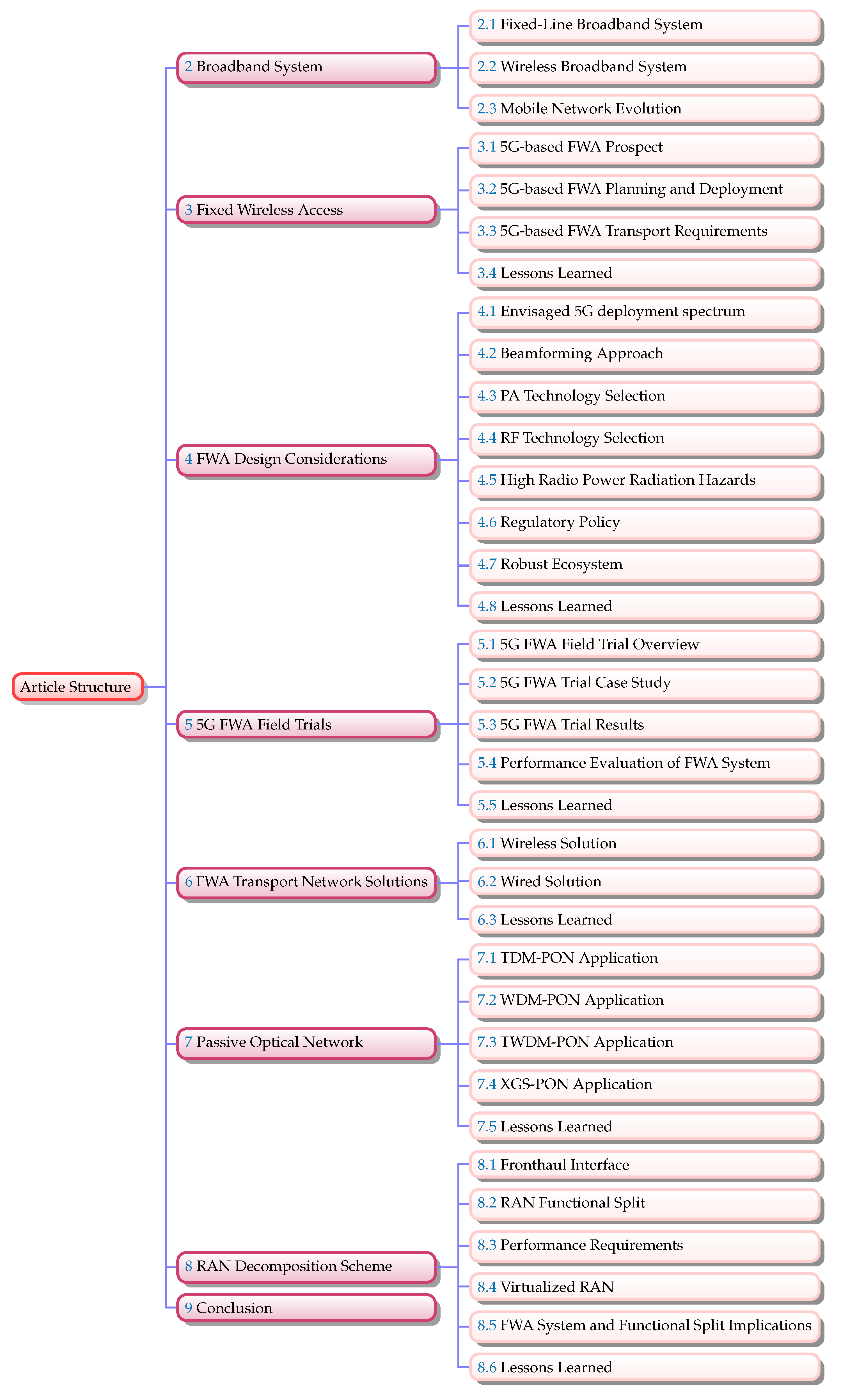
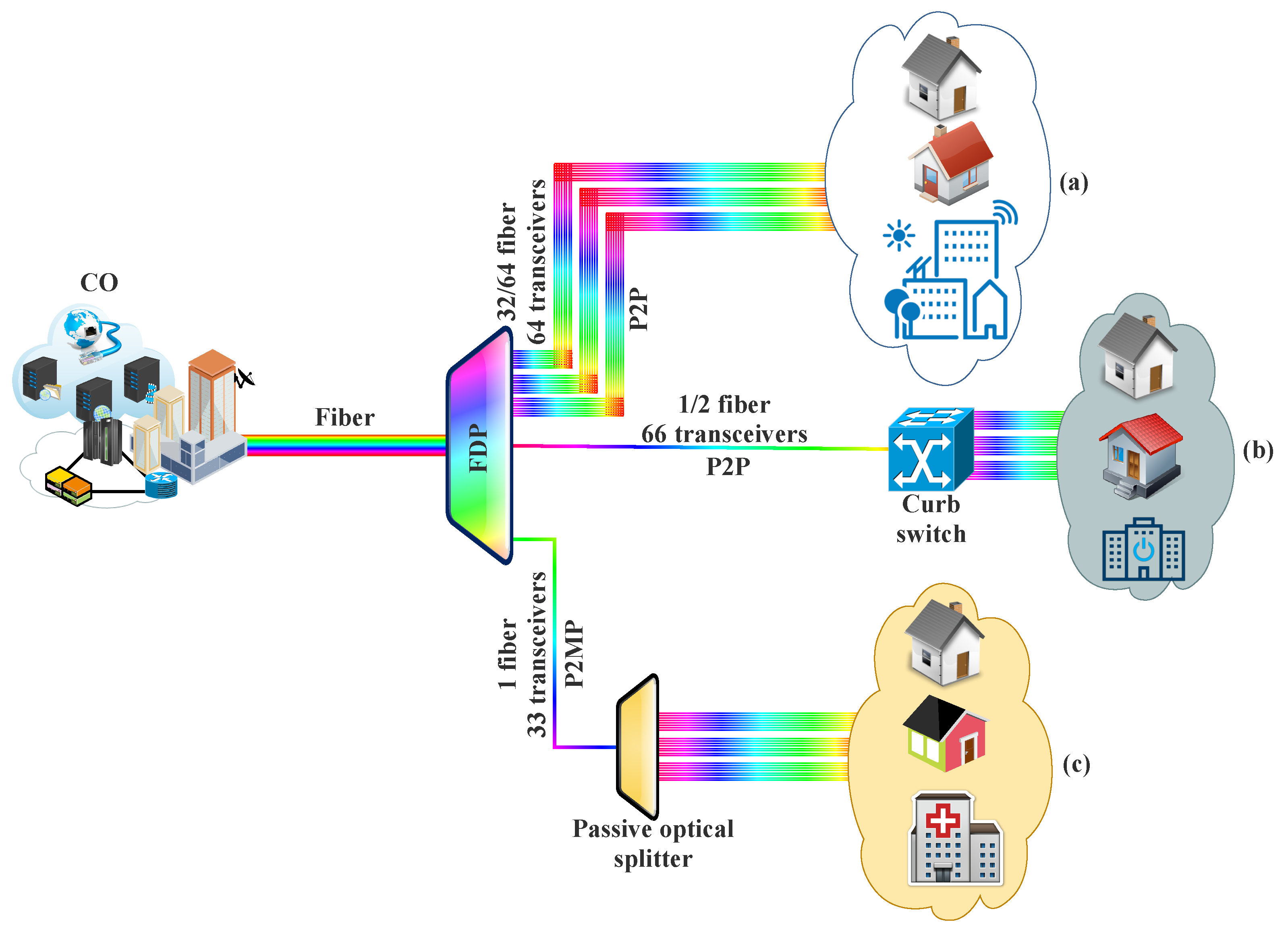
Figure 1. Schematic of the tutorial organization with related content.
Applsci 11 10427 g001
Figure 2. A typical HFC architecture.
Applsci 11 10427 g002
Figure 3. A typical BPL architecture.
Applsci 11 10427 g003
Figure 4. A typical FTTx architecture.
Applsci 11 10427 g004
Figure 5. A typical LMDS architecture.
Applsci 11 10427 g005
Figure 6. A typical FSO system.
Applsci 11 10427 g006
Figure 7. Direct broadcast satellite architecture.
Applsci 11 10427 g007
Figure 8. A typical heterogeneous database-assisted TVWS network architecture. TVA: TV Antenna, TVWS: TV white space, MSU: Macro secondary user, Macro base station (MBS), FSU: Femto secondary users, and FBS: Femto base station.
Applsci 11 10427 g008
Figure 9. Typical mobile wireless access network (a) distributed and (b) centralized architectures. BBU: Baseband unit; RRH: Remote radio head.
Applsci 11 10427 g009
Figure 10. Performance analysis of MIMO scheme for different channel widths and antenna configurations based on the cumulative distribution function of capacity.
Applsci 11 10427 g010
Figure 11. FWA deployment scenario (adapted from [27,252]).
Applsci 11 10427 g011
Figure 12. End–to–end FWA networking using MIMO and beamforming (adapted from [6,12,14,252]).
Applsci 11 10427 g012
Figure 13. Free-space path loss for different settings.
Applsci 11 10427 g013
Figure 14. Effects of (a) low-e glass, (b) non-ideal LoS condition, and (c) tree foliage on high-frequency solution (adapted from [5]).
Applsci 11 10427 g014
Figure 15. Multi–antenna schemes with and without transmit beamforming implementation.
Applsci 11 10427 g015
Figure 16. Implementation of (a) outer router for low-e glass and (b) home router for normal glass.
Applsci 11 10427 g016
Figure 17. Scanning range for different deployment scenario (a) suburban and (b) dense urban landscapes (adapted from [264]).
Applsci 11 10427 g017
Figure 18. HBF architecture for mm-wave MIMO system.
Applsci 11 10427 g018
Figure 19. Terminal antenna placement: (a) indoor window sill, (b) exterior window/wall-mounted, and (c) rooftop.
Applsci 11 10427 g019
Figure 20. Multimedia communication quality assessment model (Adapted from [357]).
Applsci 11 10427 g020
Figure 21. Potential 5G transport solutions: (a) WDM-PON, (b) microwave, (c) point-to-point, (d) OTN, and (e) Ethernet.
Applsci 11 10427 g021
Figure 22. Transport network technology classification.
Applsci 11 10427 g022
Figure 23. Potential Ethernet solutions: (a) PtP Ethernet, (b) curb-switched Ethernet, and (c) EPON.
Applsci 11 10427 g023
Figure 24. A typical PON-based transport network architecture for RAN.
Applsci 11 10427 g024
Figure 25. PON system coexistence (adapted from the work in [143]).
Applsci 11 10427 g025
Figure 26. Required MFH capacity for supporting different RF bandwidths ( B R F ) .
Applsci 11 10427 g026
Figure 27. Required MFH capacity for different sectors.
Applsci 11 10427 g027
Figure 28. Functional split options between CU and DU with emphasised PHY layer (adapted from [143,425]).
Applsci 11 10427 g028
Figure 29. Required MFH capacity for different split options.
Applsci 11 10427 g029
Figure 30. vRAN with PTNI for different use cases (a) mode A, (b) mode B, (c) mode C, and (d) mode D.
Applsci 11 10427 g030
Table 3. Data rate requirements for HD and UHD video considering various codec technologies [141].
Codec Technology
Video FormatHEVC a (Mbps)VVC b (Mbps)
720p HD (1280 × 720)21.3
1080p HD (1920 × 1080)42.6
4k UHD (3840 × 2160)127.8
a Current. b Future. HEVC: High-efficiency video coding; VVC; Versatile video coding.
Table 4. IEEE 802.11 network PHY standards.
Standard802.11802.11a802.11b802.11g802.11n802.11ac802.11ad802.11af802.11ah802.11ax802.11ayReference
Released date1997199919992003200920132012201420162019 a2019 a[173,174,175]
Frequency band (GHz)2.452.42.42.4/55602.4/52.4/52.4/560[18,132,173,174,175,176,177,178]
ModulationDSSS, FHSSOFDMDSSSDSSS, OFDMOFDMOFDMSC,OFDMOFDMOFDMOFDMSC,OFDM[173,176,177]
Range (m) b2035353870353.310001000304.810[174,176,177]
Advanced antenna schemesN/AN/AN/AN/AMIMO, up to 4 SSMIMO, MU-MIMO, up to 8 SSBFMIMO, up to 4 SSMIMO, up to 4 SSMIMO, MU-MIMO, up to 8 SSMIMO, up to 4 SS[173,175,177,179]
Bandwidth (MHz)2020202020, 4020, 40, 80, 16021606–81–1620–1608000[173,175,177,179,180]
Data rate (Mbps) c254115460069336757568.934710,53020,000[18,132,173,174,175,176,178,180]
a Expected release date; b Approximate range; c Maximum theoretical data rate (Note: the peak speed depends on the actual channel bandwidth, number of spatial streams, constellation density, and per-symbol overhead [181]).
Table 5. Basic data on IEEE 802.16 standards.
802.16802.16-2004802.16e-2005Reference
CompletedDecember 2001June 2004December 2005[159,183]
Frequency band10–66 GHz2–11 GHz2–11 GHz for fixed; 2–6 GHz for mobile applications[159,178,183,184,185]
MAC architecturePtMP, meshPtMP, meshPtMP, mesh[159,183,185]
ApplicationLoS, fixedNLOS, fixedNLOS, fixed and mobile[159,183,184,185]
Gross data rate32–134.4 Mbps1–75 Mbps1–75 Mbps[159,183,184,185]
ModulationQPSK, 16-QAM, 64-QAMQPSK, 16 QAM, 64 QAMQPSK, 16 QAM, 64 QAM[159,183,184,186]
Transmission schemeSC onlySC, 256 OFDM or 2048 OFDMSC, 256 OFDM or scalable OFDM with 128, 512, 1024, or 2048 subcarriers[159,183,185,186]
MultiplexingBurst TDM/TDMABurst TDM/TDMA/OFDMABurst TDM/TDMA/OFDMA[159,183,186]
Cell radiusOver 10 km7–10 km2–5 km[183,184]
Table 6. Mobile network evolution.
Features1G2G3G4G5GReference
Deployment1970–19801990–20042004–20102010–20202020[17,194,195,196,197,198]
SwitchingCircuitCircuit, packetPacket except for air interfaceAll packetAll packet[17,194,199,200,201]
TechnologyAnalog cellular: AMPS, NMT, TACS, RTMI, ETACS, JTACS, Netz-CDigital cellular: D-AMPS (IS-136), CDMA (IS-95), GSM, GPRS, PDC, EDGE, HSCSPUMTS (WCDMA), GSM PS & CS evols., 1x EV-DO Rel. 0, A, B; cdma2000 (IS-95C); HSPA evol.; WiMAX; LTE Rel. 8, 9LTE Rel. 10–14, WiMAX 2, Unified IP & seamless PAN/LAN/WLAN amalgam3GPP NR Rel. 15 & 3GPP NR Rel. 16[17,194,195,197,198,199,200,201,202,203,204,205,206]
Core networkPSTNPSTNPacket networkInternetInternet[17,199,200]
Data rate2 Kbps14.4–64 Kbps144 Kbps–2 Mbps200 Mbps–1 Gbps>1 Gbps[17,194,199,200,202,207]
ServiceMobile telephonyDigital voice, voice mail, SMSIntegrated high-quality video, audio, & data, streamingDynamic information access, wearable devicesDynamic information access, wearable devices with AI capabilities[17,194,199,200,201]
MultiplexingFDMATDMA/CDMACDMACDMA, SCDMA, OFDMACDMA, OFDMA, GFDM, SCDMA, VFDM[17,194,199,200,208]
Hand offHorizontalHorizontalHorizontalHorizontal & verticalHorizontal & vertical[17,194,199,200]
PAN: Personal Area Network; LAN: Local Area Network; WLAN: Wireless LAN; WAN: Wide Area Network; AMPS: Advanced Mobile Phone System; NMT: Nordic Mobile Telephone; TACS: Total Access Communication System; ETACS: European TACS; JTACS: Japanese TACS; RTMI: Radio Telefono Mobile Integrato; Netz-C: C450-20 network; D-AMPS: Digital AMPS; PDC: Personal Digital Cellular; GSM: Global System for Mobile Communications; EDGE: Enhanced Data rates for Global Evolution; GPRS: General Packet Radio Service; HSCSP: High-Speed Circuit-Switched Data; UMTS: Universal Mobile Telecommunications System; EV-DO: Evolution-Data Optimized Or Evolution-Data Only; HSPA: High-Speed Packet Access; LTE: Long-Term Evolution; WiMAX: Worldwide Interoperability for Microwave Access; SMS: Short Message Service; PSTN: Public Switches Telephone Network.
Table 7. Requirements of 4G, 5G, and the envisioned 6G.
Features4G5G6GReference
Use casesMBB• eMBB
• mMTC
• URLLC
• LDHMC/uMUB
• FeMBB/CAeC
• ELPC
• ERLLC/MBRLLC/mURLLC/EDuRLLC
• umMTC
[223,224,225,226]
Applications• Mobile Internet
• Mobile pay
• High-definition videos
• Voice
• Mobile TV
• V2X
• VR/AR/360 degree videos
• Telemedicine
• UHD videos
• IoT
• Smart city/factory/home
• Wearable devices
• Internet of Bio-Nano-Things
• Tactile/Haptic Internet
• Full-sensory digital sensing & reality
• Fully automated driving
• Space travel
• Holographic verticals and society
• Deep-sea sightseeing
• Industrial Internet
[223,224,227,228]
Network characteristicsFlat & All-IP• Virtualization
• Cloudization
• Slicing
• Softwarization
• Slicing
• Intelligentization
• Cloudization
• Virtualization
• Softwarization
[223,226,227]
Peak data rate100 Mb/s20 Gb/s≥1 Tb/s[223,224,228,229,230,231,232]
Experienced data rate10 Mb/s0.1 Gb/s1 Gb/s[223,228,231]
Spectrum efficiency3× that of 4G5–10× that of 5G[223,229]
Network energy efficiency10–100× that of 4G10–100× that of 5G[223,229]
Area traffic capacity0.1 Mb/s/m 2 10 Mb/s/m 2 1 Gb/s/m 2 [223]
Connectivity density10 5 devices/km 2 10 6 devices/km 2 10 7 devices/km 2 [223,224,228,229,230]
Latency10 ms1 ms10–100 μ s[223,224,229,231,232]
Mobility350 km/h500 km/h≥1000 km/h[223,229]
Technologies• D2D communications
• OFDM
• Turbo code
• MIMO
• Hetnet
• Carrier aggregation
• ICIC
• Unlicensed spectrum
• LDPC & polar codes
• Flexible frame structure
• Massive MIMO
• Ultradense networks
• NOMA
• SDN/NFV/network slicing
• Cloud/fog/edge computing
• AI/machine learning
• SM-MIMO
• Laser & VLC
• LIS and HBF
• OAM multiplexing
• Blockchain-based spectrum sharing
• Quantum communications & computing
[223,225,226,229,231]
Frequency bandsSub-6 GHz (0.6–6.0 GHz)• Sub-6 GHz
• mm-wave for fixed access (30–300 GHz)
• Sub-6 GHz
• mm-wave for mobile access
• Exploration of higher frequency and THz bands (0.06–10 THz)
• Non-RF (e.g., VLC, optical, etc.)
[223,224,226,227,230,231,233]
Reliability (%)99.9999.99999.99999[224,229,232]
IoT: Internet-of-Things; D2D: Device to device; ELPC: extremely low-power communications; AR: augmented reality; ERLLC: extremely reliable and low-latency communications; EDuRLLC:Event-defined uRLLC; uHSLLC: ultra-high-speed-with-low-latency communications; MBRLLC: mobile broadband reliable low latency communication; mURLLC: massive ultra-reliable, low latency communications; uMUB: ubiquitous mobile ultrabroadband; eMBB: enhanced mobile broadband; uHDD: ultrahigh data density; LDHMC: long-distance and high-mobility communications; FeMBB: further-enhanced mobile broadband; CAeC: Contextually agile eMBB communications; NFV: network function virtualization; mMTC: massive machine-type communications; UHD: ultrahigh definition; SDN: software-defined networking; URLLC: ultra-reliable and low-latency communications; umMTC: ultra-massive machine-type communications; V2X: vehicle to everything; VR: virtual reality; AI: Artificial intelligence; LDPC: low-density parity-check codes; KPI: key performance indicator; ICIC: Inter-cell interference coordination; Hetnet: Heterogeneous network; mm-wave: Millimeter-wave; LIS: Large intelligent surface; HBF: Holographic beamforming; OAM: Orbital angular momentum; VLC: Visible-light communications; OFDM: Orthogonal frequency-division multiplexing; NOMA: Non-orthogonal multiple access; MIMO: Multiple-input multiple-output; SM-MIMO: Supermassive MIMO.
Table 8. Broadband technologies comparison.
TechnologyDown-/Upstream Rate aEfficiency Range (km) aAdvantagesLimitationsReference
Wired Broadband Technologies
ADSL, ADSL2, ADSL2+24/3 Mbps5
  • Employs existing POTS
  • Fast installation
  • Limited bandwidth
  • Distance sensitive bandwidth
  • Small efficiency range
[16,19,234,235]
VDSL, VDSL2, Vectoring100/40 Mbps1
HFC40/30 Mbps b2–100 c
  • Employs existing cable TV network
  • Fast installation
  • High bandwidth
  • Limited bandwidth per-channel
  • Shared bandwidth
  • Very low upstream rates
[16,19,234,235]
BPL200/2 Mbps1–3
  • Employs existing power lines
  • Cost-intensive
  • Shared bandwidth
  • Small efficiency range
  • Interference problem
[16,18,236]
Fiber10/10 Gbps (even more)10–60
  • Relatively unlimited bandwidth
  • High efficiency range
  • Less susceptible to interference
  • Cost-intensive
[16,18,19,234,235,236]
Wireless Broadband Technologies
LMDS155/1.54 Mbps2–8
  • PtMP
  • Higher capacity
  • Fast deployment
  • Scalable
  • LoS
  • High deployment cost
  • Not standardized
[16,18,237,238]
MMDS1.5/0.3 Mbps56
  • PtMP
  • Lower deployment cost
  • NLOS
  • Lower capacity
  • Not standardized
[16,18,237,238]
FSO5/3 Gbps d4 d
  • Unlicensed spectrum
  • Low setup cost
  • LoS
  • Susceptible to weather condition
  • Small efficiency range
[16,166]
Wi-Fi (802.11n)600/600 Mbps0.2
  • Ethernet compliant
  • Cost-effective
  • Fast implementation
  • Ease of deployment
  • Shared medium
  • Small efficiency range
[16,19,234,235]
WiMAX6/4 Mbps60
LTE (Advanced): 4G100/30 (1000/30) Mbps e3–6
  • Very appropriate for remote area coverage
  • Fast implementation
  • Ease of deployment
  • Mobile terminals use existing cellular network
  • Shared medium
  • Limited frequencies
  • Limited applications
[16,19,234,235]
HSPA/HSPA+: 3G100/40 Mbps3
5G10/20 Gbps3–6
  • Low latency
  • High capacity
  • High reliability
  • Spectrum flexibility
  • Massive connectivity
  • Higher frequency bands
  • Advanced multi-antenna schemes
  • Shared medium
  • Limited frequencies
[19,234,235]
Satellite30/10 Mbps1000–36,000
  • Very appropriate for remote area coverage
  • Appropriate for multicast applications
  • Large coverage
  • Fast implementation
  • Run time latency
  • Asymmetric
  • Cost-intensive
  • Limited per subscriber capacity
[16,19,234,235]
a Technical standard maximum [235]; b Depends on the DOCSIS version (standard); c Depends on the amplification; d Depends on the Channel state and distance; e Depends on the employed frequency spectrum.
Table 9. Parameters for different type of terrains for SUI model [275,276].
Terrain
ParameterABC
a4.64.03.6
b0.00750.00650.005
e12.617.120
Table 10. FCC power limits for 28 GHz and 39 GHz bands.
Equipment ClassPower (EIRP)Reference
Base Station75 dBm/100 MHz[264,321,322,323,324]
Mobile Station43 dBm[12,264,321,323,324,325]
Transportable Station55 dBm[12,264,321,322,324,325,326]
Table 11. Subjective mean opinion score evaluation.
ExperienceScore
Bad1
Applsci 11 10427 i001
Poor2
Applsci 11 10427 i002
Fair3
Applsci 11 10427 i003
Good4
Applsci 11 10427 i004
Excellent5
Applsci 11 10427 i005
Table 12. Comparison of potential transport network solutions for FWA.
SolutionAdvantagesLimitationsReference
Optical systems
Dedicated fiber
  • Uncomplicated as additional equipment is not required
  • Colorized SFPs are not required
  • Employs low-cost optics
  • Supports high capacity and low latency use cases
  • Demands fiber-rich deployment
  • Poor scalability
  • Uneconomical for certain centralized deployments
[5,8,11,47,143,371,372,376,384,387]
TWDM-PON (i.e., GE-PON, XG-PON, and NG-PON2)
  • Relative low-cost potential
  • Enhanced fiber capacity with multiple channels per fiber
  • Capability for system reuse between FTTH and FWA customers
  • Limitation in the supported capacity and low-latency services
[5,8,11,25,47,143,371,372,376,387]
WDM-PON (i.e., WS-WDM-PON, WR-WDM-PON)
  • Dedicated solution for RAN transport where ODN deployment can be adapted for the preferred RAN deployment
  • Enhanced fiber capacity with multiple channels per fiber
  • Limitation in reusing the existing FTTH infrastructure
  • Potential concerns for future migration of customers to FTTH in which separate ODN will be required
  • Conventional scenario low fan-out limits the need for DWDM (i.e., CWDM is appropriate)
[5,8,11,25,47,143,371,372,376,387]
PtP WDM overlay (i.e., NG-PON2)
  • Potential reuse of the existing fiber plant for offering PtP transport solution.
  • Supports high capacity and low latency
  • High related footprint and costs of ODN filters
[5,8,11,25,47,143,371,372,376,387]
Active systems
Ethernet (i.e., CPRI over Ethernet), OTN
  • Potential reuse of the existing infrastructure
  • Appropriate for active network deployment
  • Native OAM and FEC
  • Colored SFPs no required at the DUs
  • Offers native protection
  • Enhanced scalability
  • Economical
  • High power consumption (additional electronics)
  • RAN split options are virtually limited by the deployed active equipment
  • High footprint (cooling)
  • Concerns on system performance (latency, synchronization)
[5,11,25,47,143,371,372,376,384,387]
Wireless systems
LTE, 5G
  • Flexible deployment
  • Offers lower deployment cost than fiber solution
  • Shared spectrum between the access and transport
  • More spectrum required
  • Distance limited
[5,11,47,143,371,372,376,387]
MW, FSO
  • Can complement fiber-based technologies
  • Flexible deployment
  • Cost-effective solution in areas where fiber is not available
  • Susceptible to weather conditions
  • Distance limited
  • LoS constraint limits network equipment placement
[5,11,47,143,376,378]
Table 13. Typical transmission parameters.
ParameterSymbolTypical Value
Number of antennasM1–16
Number of sectors N s 1–3
Line codeC10/8
Control overheads C w 16/15
Sampling rate (MHz) R s 15.36/10
Bit resolution N r e s 15
Table 14. Typical transmission parameters considered.
Parameter (UL/DL and 5G/LTE)Typical Value
Baselines bandwidth 100 MHz
Number of sub-carrier 1200 SC/20 MHz
OFDM symbol rate 14 symbol/ms
MIMO layer 8
Number of antenna ports 32
Modulation schemeUL64 QAM
DL256 QAM
Average content sizeUL30 Bytes
DL20 Bytes
LTE peak data rateUL50 Mbps
DL150 Mbps
Scheduling/control signaling overheadUL24 Mbps, 2640 Mbps
DL16 Mbps, 133 Mbps
MAC informationUL80 Mbps, 120 Mbps
DL121 Mbps, 713.9 Mbps
Spectrum Usage5G99%
LTE90%
Upper bound estimation margin5G120%
LTE100%
Maximum number of UE 1000
% UE reporting requests 10%
Publisher’s Note: MDPI stays neutral with regard to jurisdictional claims in published maps and institutional affiliations.

