Article

Offline Joint Network and Computational Resource Allocation for Energy-Efficient 5G and beyond Networks

1
Department of Informatics, Aristotle University of Thessaloniki, 54124 Thessaloniki, Greece
2
Center for Interdisciplinary Research and Innovation, 57001 Thessaloniki, Greece
3
Nextworks, 56122 Pisa, Italy
*
Authors to whom correspondence should be addressed.
Submission received: 9 October 2021 / Revised: 26 October 2021 / Accepted: 5 November 2021 / Published: 9 November 2021
(This article belongs to the Special Issue 5G and Beyond Fiber-Wireless Network Communications)

Abstract

:
In order to cope with the ever-increasing traffic demands and stringent latency constraints, next generation, i.e., sixth generation (6G) networks, are expected to leverage Network Function Virtualization (NFV) as an enabler for enhanced network flexibility. In such a setup, in addition to the traditional problems of user association and traffic routing, Virtual Network Function (VNF) placement needs to be jointly considered. To that end, in this paper, we focus on the joint network and computational resource allocation, targeting low network power consumption while satisfying the Service Function Chain (SFC), throughput, and delay requirements. Unlike the State-of-the-Art (SoA), we also take into account the Access Network (AN), while formulating the problem as a general Mixed Integer Linear Program (MILP). Due to the high complexity of the proposed optimal solution, we also propose a low-complexity energy-efficient resource allocation algorithm, which was shown to significantly outperform the SoA, by achieving up to 78% of the optimal energy efficiency with up to 742 times lower complexity. Finally, we describe an Orchestration Framework for the automated orchestration of vertical-driven services in Network Slices and describe how it encompasses the proposed algorithm towards optimized provisioning of heterogeneous computation and network resources across multiple network segments.

1. Introduction

Beyond 5G (B5G) and 6G networks are envisioned to meet a plethora of service requirements supporting high resource and technology heterogeneity, while adopted architectural paradigms, such as Centralized-Radio Access Network (C-RAN) and Network Function Virtualization (NFV), offer the necessary high flexibility and configurability to the network. The increasing use of NFV, in particular, to “softwarize” functions and applications [1,2,3] (i.e., decouple the function logic from the underlying hardware running the actual code) in numerous Open System Interconnection (OSI) layers has transformed the majority of “traditional” network functions (e.g., Network Address Translation (NAT), firewall, load balancing, and Intrusion Detection/Prevention System (IDPS)) into Virtual Network Functions (VNFs), which can run on generic computational infrastructure that can be dynamically deployed. Although we use the generic term “Central Processing Unit (CPU) resources” to refer to this computational infrastructure, our model and ensuing analysis can capture any type of computational device, including Graphics Processing Units (GPUs), Field Programmable Gate Arrays (FPGAs) and other computational acceleration platforms.
The NFV-supporting physical computational infrastructure contains a number of nodes, including traffic-forwarding switches and computational nodes of different capabilities that can host VNFs in the form of Virtual Machines (VMs), containers, or unikernels. Although traditional cellular architectures were mainly equipped with cloud servers, located at distant locations offering high computational power at low cost, the need for supporting ultra-low latency B5G services has motivated Multi-Access Edge Computing (MEC) [4]. To this end, MEC nodes offer computational capabilities very close to the user, often being attached to Base Stations (BSs), and are able to achieve ultra-low latency at the expense of high cost, thus leading to a nontrivial cost/distance tradeoff that needs to be quantitatively examined.
The above flexible deployment introduces a new exploitable “degree of freedom” regarding the potential location of the deployed VNFs (referred to as the “VNF placement problem” [5,6]) but also introduces new challenges to traditional user association and traffic routing problems, since these problems are strongly coupled with the location of the nodes running the VNFs. Furthermore, the VNFs themselves typically operate in synergy with each other to form Service Function Chains (SFCs), i.e., ordered sequences of VNFs which process packets in an End-to-End (E2E) manner, within the operator’s network, and according to specific rules matching a given service request. This ordering adds a crucial constraint to the routing problem, as the SFC is considered to successfully meet the service request only when the selected routed path passes through the VNFs comprising the specific SFC in exactly the order specified; for example, if an SFC is described by the ordered sequence NAT→Firewall→NAT, then all packets belonging to this SFC must be processed by only these three VNFs in the specified order.
The above discussion motivates the need to jointly study VNF placement alongside computational and communication resource allocation in a mobile network, while satisfying the SFC, throughput, and delay requirements [7,8,9]. In addition, B5G is expected to include a variety of different access and transport technologies with distinct characteristics that should be jointly studied. Specifically, apart from fiber links interconnecting the physical nodes, wireless links may also be deployed as an X-haul transport solution, to offer high flexibility close to the Access Network (AN) [10]. Millimeter wave (mmWave) constitutes a very promising candidate to serve this purpose, due to its high bandwidth availability and antenna gains that are able to compensate for the higher path loss in this band. Moreover, for the AN, comprised of gNodeBs (gNBs) densely overlaid with Small Cells (SCs), 5G-New Radio (5G-NR) proposes the use of multiple frequencies (including mmWave). Hence, a holistic network resource planning study should jointly consider: (1) all types of technologies, e.g., 5G-NR, mmWave, fiber, along with their benefits and constraints, and (2) the allocation of all different resource types (i.e., communication, computational, and storage).
It is also crucial to consider the whole network path from the traffic source to the destined User Equipment (UE), so as to satisfy the service latency constraint and offer true E2E optimality, within the operator’s network boundaries. Furthermore, achieving high energy efficiency is of utmost importance not only to limit the network operator’s operational costs (thus, increasing its revenue) but also to decrease the Information and Communications Technology (ICT) carbon footprint, leading to eco-friendly B5G networks. Hence, we focus on energy-efficient network resource planning solutions to jointly solve the user association, VNF placement (SFC chaining), and traffic routing problem in the highly heterogeneous B5G networks.
In addition, although the discussion so far has focused on (energy-optimal) establishment of the data plane to satisfy the requested services, there is a strong need for an accompanying flexible management and control plane that supports the actual dynamic provisioning and/or configuration of resources in B5G network infrastructures. Network Slicing is considered as a key enabling concept for achieving a high degree of automation in the provisioning of services in B5G networks, allowing, at the same time, resource sharing within the operator’s network and the fulfilment of performance requirements depending on the service type (i.e., enhanced Mobile Broadband – eMBB, ultra Reliable Low Latency Communication – uRLLC, and massive Machine Type Communication – mMTC). Network Slicing improves the way network and computational resources are allocated and also offers the possibility of performing runtime optimization that targets Quality of Service (QoS) preservation as well as energy-efficient deployments and the reduction of operational cost.
Combining Network Slicing, Software Defined Networking (SDN), and NFV/MEC orchestration techniques with advanced strategies for resource planning, VNFs of different types, potentially belonging to different network segments (radio, core, and transport network), can be placed and configured in an optimal manner, while the SFC connectivity is guaranteed through the establishment of optimized jointly computed network paths.

1.1. Related Work

The joint problem of VNF placement, SFC chaining, and routing in wired networks, mostly targeting cloud environments in the network core, has been widely studied with tools such as Dynamic Programming [11], knapsack algorithms [12], Monte Carlo Tree Search [13], and Benders decomposition [14]. The above works, including the recent ones in [7,15,16], formulate NP-hard Mixed Integer Linear (MILP) and Nonlinear Programs, for which heuristic algorithms are proposed and numerically evaluated. Hence, their essential differences lie in the considered constraints and objectives (i.e., minimum total network power consumption in [15], link utilization, overhead, and server power consumption in [16], and monetary profit in [7]). Models with a distinct MEC/cellular flavor appear in [17,18] (see also survey in [19]); however, [17] does not consider power consumption, while [18] models the link constraints more abstractly than in our paper and uses a different objective (i.e., minimize maximum link utilization).
Regarding Network Slicing, SDN, and NFV/MEC orchestration, many platforms, both commercial and open-source, provide functionalities that target the management and control of technology-specific resources. The Open Source Management and Orchestration (MANO) framework proposed by the European Telecommunications Standards Institute (ETSI), considered the most mature standardized solution for Network Service Lifecycle Management (LCM) [20], also supports Network Slicing but is not currently targeting the management of radio elements. On the other hand, O-RAN, being the most successful of the open Radio Access Network (RAN) initiatives, targets specifically the virtualization and management of radio functions [21]. During Horizon 2020 5G Infrastructure Public Private Partnership (5G-PPP) phase 2, some research initiatives focused on prototyping Network Slicing solutions considering (mostly) computational resources [22] and integrating, in some cases, mechanisms for joint management of the transport [23] and radio network segments [24].

1.2. Research Gap

Most of the work on resource allocation (i.e., VNF placement, SFC chaining and routing) mentioned in Section 1.1 does not consider mobile networks and, even when they do, they ignore the wireless AN segment. The last remark motivates our paper, which also studies joint VNF placement and routing in a MEC/cloud-enabled heterogeneous mobile network consisting of macro BSs and SCs. We explicitly include the AN, as well as potential wireless X-haul links, while accounting for the inherent wireless channel fluctuations. Hence, this paper extends the concrete and detailed communication model of [25] by adding all necessary controls for the computational resources and by modeling the associated delay and capacity constraints. In addition, the extensive technical documentation released by Standards Developing Organizations (SDOs) (such as ETSI) regarding the E2E network efficiency of mobile networks in conjunction with the NFV-supporting infrastructures [26,27], indicate that solutions targeting E2E network energy efficiency are of prime importance.
On the other hand, the multiplicity of technology-specific orchestration platforms presents interoperability challenges, which motivates current research in 5G and B5G networks towards delivery of E2E Network Slicing solutions that support the orchestration and management of lheterogeneous resources in distributed edge to cloud infrastructures and across the different network segments [28], i.e., radio, core, and transport. In addition, although there are solutions that optimize the hardware (optimized design of dedicated solutions) or the job allocation in the computing nodes, they provide local optimization benefits, while overlooking the holistic network optimization. To this end, so far, there has been no complete solution for a unified Orchestration Framework having a holistic view of the entire network (potentially by integrating existing technology-specific platforms such as ETSI MANO and O-RAN) and using it for the management and orchestration of Vertical-driven services within E2E Network Slices provisioned and configured over multi-technology components. The search for such a solution provides additional motivation for our paper.

1.3. Our Contributions

The paper’s contributions are summarized as follows:
  • We formulate a concrete joint user association, traffic routing, and VNF placement optimization problem targeting at the overall E2E network performance optimization, with minimal assumptions, that accounts for both communication and computation resources in all segments of a mobile network (i.e., AN, edge, and core) and explicitly account for the AN segment, typically ignored in the literature.
  • Due to the NP-hardness of the resulting problem, we also propose a heuristic algorithm, evaluate its performance via simulations and demonstrate its superior performance compared with other State-of-the-Art (SoA) algorithms. The proposed solutions can be applied for internode network optimization, in conjunction with approaches targeting intranode optimization for maximum performance.
  • Expanding upon our previous work in [29], we also describe the proposed orchestration solution, which, integrated with the proposed algorithm, enables the automated and optimized provisioning and configuration of heterogeneous computational and network resources across all network segments, targeting the orchestration of virtualized services according to the expected performance requirements and the specified SFC.
Our formulation and algorithm can also be employed by a mobile network operator as an offline tool, during the network planning stage, to provide quantitative answers on the power expenditure and computational resources (both of them major components of Operational Expenditure (OPEX) and Capital Expenditure (CAPEX)) required to support a given set of services.
The rest of the paper is structured as follows: Section 2 describes the system model and problem formulation, while the proposed heuristic and the employed Orchestration Platform are presented in Section 3 and Section 4, respectively. Our performance evaluation methodology and comparison between the optimal solution and other SoA algorithms is described in Section 5 with the actual results being presented in Section 6. Section 7 concludes the paper. Notation-wise, sets are denoted with calligraphic symbols V ,   F etc. and = Δ denotes equality by definition.

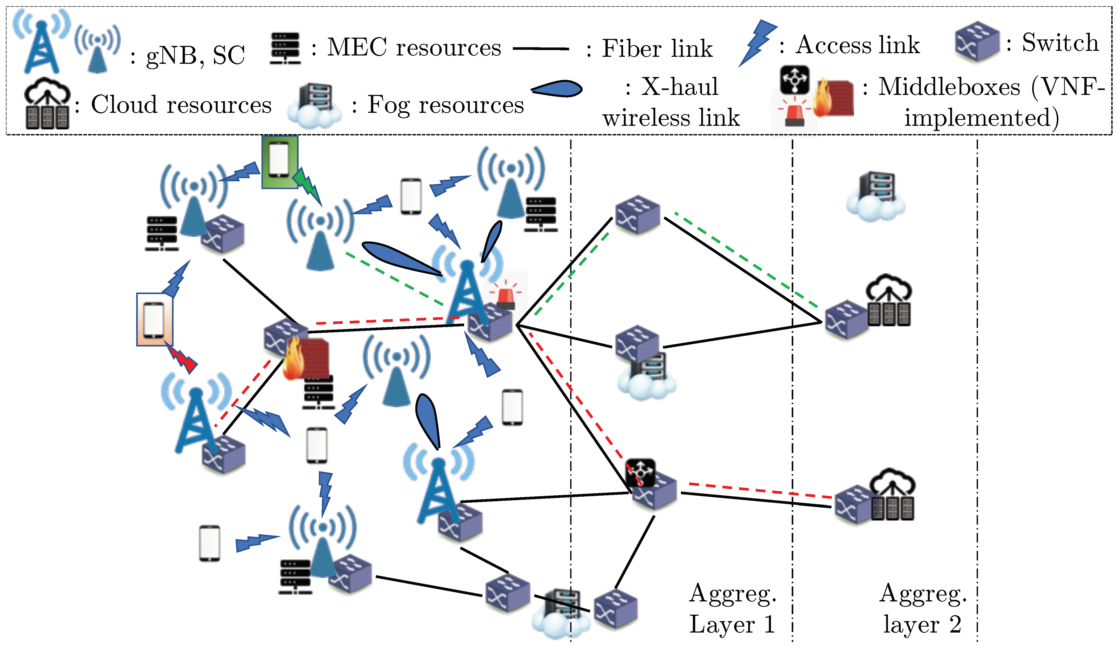
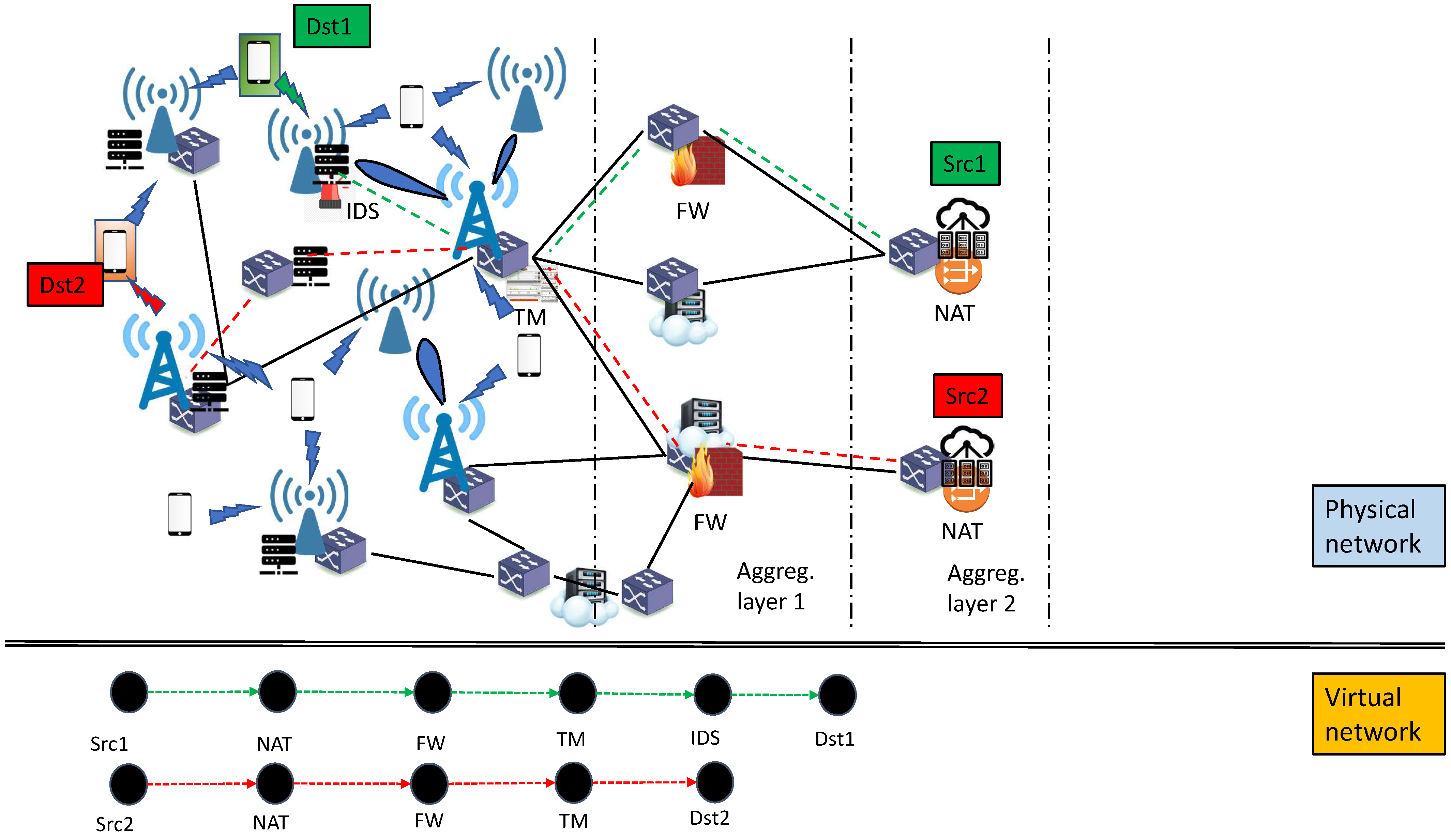
2. System Model and Problem Statement

We consider the RAN and Core segments of a mobile network and model them as a graph G ( V ,   E ) , where V is the set of nodes (excluding mobile users) and E is the set of non-access edges/links among them, as illustrated in Figure 1 (which also shows access links, for completeness). The nodes in V comprise gNB and/or SCs (hereafter referred to as BSs) in the RAN, as well as switches/routers and other middlebox devices (e.g., load balancers, firewalls, etc.) in the Core. These devices typically operate as VNFs running in virtual instances (e.g., VMs, containers, etc.) utilizing computational resources collocated with network nodes.
Each link e = ( u ,   v ) E , where u ,   v V , can be wired or wireless (the latter enables wireless X-hauling, typically mmWave), has a communication capacity c e , and induces a delay δ e (being the sum of transmission and propagation delays) to all packets traversing it. We partition E into the sets E f i and E w l of wired/fiber and wireless links, respectively, and denote with V s w V the set of nodes in V that have at least one incident link in E f i (i.e., u V s w if there exists w V such that ( u ,   w ) E f i ). We abstractly refer to the nodes in V s w as “switches” since most fiber links in a mobile Core are typically Point-to-Point links among switches or routers. For modeling reasons, and although all physical links are inherently bidirectional, we explicitly distinguish between links ( u ,   v ) and ( v ,   u ) in E (and also for E f i , E w l ). We denote with h ( e ) = u and t ( e ) = v the head and tail, respectively, of directed link ( u ,   v ) .
The UEs are not included in V but rather in J (we also define V ˜ = Δ V J ). Each UE j J connects to a BS a A ( j ) V , where the dependence on j captures the typical signal level-based association rules. We define A = Δ j J A ( j ) as the set of all BSs and S ( a ) = Δ j : a A ( j ) J as the set of UEs which may be served by BS a A . We focus on Downlink (DL) and consider the set of DL AN links E A N = Δ ( a ,   j ) : a A ,   j S ( a ) with E ˜ = Δ E E A N . To capture the underlying Physical layer constraints in the air interface, we also assume that each BS a A has a maximum number of N ¯ a ( R B ) Resource Blocks (RBs) to allocate to the UEs in S ( a ) .
Let V c V be the set of network nodes which also have computational (i.e., CPU) resources able to host one or more VNFs. Additional computational resources such as memory and storage can be similarly handled and are omitted for simplicity and without loss of generality. For each node y V c , we denote with c y the amount of CPU resources, measured in Giga-Floating Point Operations per Second (GFLOPS). We denote with F the set of all available VNFs (viewed as complete software stacks) that can be deployed and allow for multiple instances of a given VNF in the same or different nodes depending on network traffic. Each VNF f F is described by the tuple f = Δ ( T f ,   π f ,   w f ,   τ f ) , where T f is an identifier of the VNF’s functionality (e.g., NAT etc.), π f > 0 is the data processing capacity of the VNF (in Mbps), w f > 0 is the amount of CPU resources (in GFLOPS) required for the VNF’s operation, and τ f > 0 is the data processing delay experienced by an individual data packet as it passes through the VNF. To ensure proper service endpoints, we also introduce the set F d u m = Δ { f d u m 1 ,   f d u m 2 } of two “dummy” VNFs and include it into F . The VNFs f F d u m F are characterized by π f = , w f = 0 , τ f = 0 , which implies that the “dummy” VNFs work transparently, w.r.t., our model.
Let C be the set of SFCs, where SFC ρ C is described by the ordered sequence ρ = Δ f d u m 1 ,   f 1 ( ρ ) , , f N ρ ( ρ ) ,   f d u m 2 , where N ρ is the number of non-dummy VNFs in ρ and f i ( ρ ) F F d u m . The traffic of ρ is properly served only if it passes through the VNFs in ρ exactly matching the specified order. We also write f ρ to state that VNF f is contained in ρ and define R ρ = Δ { f F : f ρ } . An equivalent description for ρ is via a directed graph G ( ρ ) ( V ( ρ ) ,   E ( ρ ) with the virtual node set V ( ρ ) = Δ { f d u m 1 ,   f 1 ( ρ ) ,   f 2 ( ρ ) , ,   f N ρ ( ρ ) ,   f d u m 2 } (i.e., each VNF f ρ is a node of V ( ρ ) ) and the virtual edge set E ( ρ ) = f d u m 1 ,   f 1 ( ρ ) ,   f i ( ρ ) ,   f i + 1 ( ρ ) 1 i N ρ 1 f N ρ ( ρ ) ,   f d u m 2 describing the relative order of the VNFs (see bottom part of Figure 2 for an example of such a virtual graph). For any virtual edge e E ( ρ ) , we denote with h ( e ) , t ( e ) F the respective VNFs at the head and tail of e .
Each UE j J requests a service type q j Q , with q j = Δ ( s q j ,   r q j ,   δ q j ,   ρ q j ) , where s q j V is the “source” node of the service (the “destination” node of service q j is UE j), r q j > 0 is the E2E required throughput, δ q j > 0 is the E2E maximum allowed latency, and ρ q j C is the required SFC. We explicitly allow for sharing a VNF instance among two (or more) different SFCs, provided the VNF can meet the requirements imposed by the aggregate traffic of the services sharing this VNF. Furthermore, for each UE j, we use our knowledge (or estimates) of the Signal to Interference plus Noise Ratio (SINR) σ a , j of link ( a , j ) E A N and the requested service rate r q j to compute the number of RBs N a , j ( R B ) needed to achieve this rate on link ( a , j ) . Assuming frequency-flat slow fading [25], we consider the simple case of uniform BS power allocation among the RBs, so that each RB is assigned a power of p a ( R B ) .
We can now succinctly state the problem to be solved as follows: for a set of service requests Q generated by a set of UEs J , we seek to jointly determine the location of the VNFs that must be deployed to properly serve the requested SFCs, as well as the E2E routing path for each request, so that the total system power consumption is minimized (equivalently, the energy efficiency in bits/Joule over all requests is maximized). Computation of the selected routing path also includes determination of the BS to which each UE attaches to.

2.1. Power Consumption Model and Problem Formulation

Unless otherwise stated, we consistently use the following indices ranging over the respective sets: j J , a A , q Q , y V c , y ˜ V c J , f F , q Q , u ,   v ,   w V , m ,   n V s w . We introduce the decision variables x j , a as the Boolean indicator of whether UE j attaches to BS a, and ϕ y ˜ , f , q as the Boolean indicator of whether VNF f requested by service q is deployed on node y ˜ . Furthermore, θ e e , q (or its alias θ u , v e , q ) is the Boolean indicator variable of whether the directed physical link e = ( u ,   v ) E belongs to the physical path in G onto which the virtual edge e E ( ρ q ) is mapped for SFC ρ q . Finally, N f , y ˜ is the number of instances of VNF f deployed on node y ˜ .
Towards superior energy-saving performance, we employ resources, devices, and links only when needed. Specifically, collocated CPU resources at node y are employed only when y actually runs deployed VNFs, as captured by the Boolean indicator variable ξ y . Hence, the power consumed by CPU processing at node y is given by
P y ( C P U ) = P y ( C P U , i ) ξ y + P y ( C P U , m ) P y ( C P U , i ) · U y ,
where P y ( C P U , m ) , P y ( C P U , i ) are the maximum and idle power of the CPU deployed at y and U y = Δ f F N f , y w f c v is the CPU load factor at y [15].
Similarly, for a fiber link ( n ,   m ) E f i , the Boolean variable z n , m indicates whether the link actually carries traffic, in either link direction, for any request. To examine whether link ( n ,   m ) E f i carries any traffic in the specific direction from n to m, we introduce the Boolean variable w n , m , which implies that it must hold
z m , n w m , n z m , n w n , m   ( n ,   m ) E f i .
We denote with ψ n the Boolean variable of whether the switch of node n V s w is actually used. There exist certain consistency relations between these variables as shown in (3) below, where C 1 > 0 is a sufficiently large constant.
q Q e E ( ρ q ) θ e e , q C 1 w e ,   e E f i , e E f i : h ( e ) = n w e + e E f i : t ( e ) = n w e C 1 ψ n ,   n V s w .
The above relations capture the fact that a node is active (i.e., ψ n = 1 ) only if it has active incident links carrying traffic and, similarly, a link is active only if it is carrying traffic for one of the requested SFCs.
The total power consumed by the switch in node n is
P n ( s w ) = P i d l e ( s w ) ψ n + P p o r t m V s w : ( n , m ) E f i z n , m ,
where P i d l e ( s w ) denotes the switch idle power and the second term accounts for the active fiber links of the switch, with P p o r t being the power consumed by each active port [15].
The power expenditure model for the mmWave links in E w l follows [25] (see Equations (7)–(10) therein); specifically, the power consumed on link e E w l is given by
P e ( m m W ) = N R F ( m m W ) χ e P e ( m m W , i ) + Δ e ( m m W ) F ( e ) ,
where N R F ( m m W ) is the number of Radio Frequency (RF) chains in the link, P e ( m m W , i ) is the idle power of the link’s transmitter, e = Δ q Q e E ( ρ q ) θ e e , q / b e is a load-dependent variable (where b e is the utilized bandwidth of link e), Δ e ( m m W ) is a slope parameter depending on the power electronics used in the link’s transmitter, and F ( · ) is a piecewise-linear function accounting for the nonlinear dependence between achieved throughput and power expenditure. Finally, χ e is a Boolean indicator variable for whether link e is actually used to serve any traffic; if not, the link’s transceiver is turned off.
The power expenditure for the AN links in E A N is similarly modeled as follows: the power expended by a gNB BS a A is
P a ( g N B ) = N R F ( g N B ) · μ a P a ( g N B , i ) + Δ a ( g N B ) j S ( a ) x j , a p a ( R B ) N a , j ( R B ) ,
where μ a is the Boolean indicator for whether BS a actually serves any UEs, and N R F ( g N B ) , P a ( g N B , i ) , and Δ a ( g N B ) have the same semantics as in (5). For an SC BS, it similarly holds
P a ( S C ) = N R F ( S C ) · μ a P a ( S C , i ) + Δ a ( S C ) j S ( a ) x j , a p a ( R B ) N a , j ( R B ) .
We use the clever trick of [25] to convert the activation/power saving constraints into a set of linear constraints by introducing auxiliary Boolean variables χ e , for e E w l , and ν a , for a A
χ e + C 2 σ e 1 ,   e E w l , 1 C 2 χ e q Q e E ( ρ ) q θ e e , q C 2 ( 1 σ e ) ,   e E w l , 1 C 1 ν a j J x j , a C 2 ( 1 ν a ) , μ a + C 1 ν a 1 , a A .
In addition to the basic self-consistency conditions
ϕ s q j , d u m 1 , q j = ϕ j , d u m 2 , q j = 1 ,   j J , ϕ y ˜ , f d u m 1 , q j = 0 ,   j J ,     y ˜ V c { s q j } , ϕ y ˜ , f d u m 2 , q j = 0 ,   j J ,     y ˜ V c { j } ,
and
ϕ j , f , q = 0 ,   j J ,     q Q ,     f F { f d u m 2 } , ϕ y ˜ , f , q = 0 ,   q Q ,     f F R ρ q ,     y ˜ V c J , θ a , j e ˙ q j , q j = x j , a ,   j J ,     a A ,
following from the definitions, where e ˙ q j is the “last” virtual edge in E ( ρ q ) , i.e., t e ˙ q j = 1 , we also impose the constraints:
y V c ϕ y , f , q = 1 ,   q Q ,     f R q F d u m , a A ( j ) x j , a = 1 ,   j J , x j , b = 0 ,   b A ( j ) ,
which require that each requested VNF must be deployed at a node and that each UE must properly attach to exactly one of its allowable BSs (i.e., those BSs which can allocate a sufficient number of Resource Blocks to serve its requested traffic).
The constraint
q Q : f ρ q ϕ y , f , q r q N f , y π f ,   f F ,     y V c , f F N f , y w f c y ,   y V c , f F F d u m N f , y C 1 ξ y ,   y V c ,
ensures that the number of deployed VNF instances on a node is sufficient to meet the data processing requirements for the incoming traffic and does not exceed the amount of available CPU resources, while ensuring that the computational node is deployed only when needed.
The link and BS capacity constraints are captured as follows:
q Q e E ( ρ q ) θ e e , q r q c e ,     e E ˜ , j S ( a ) N a , j ( R B ) N ¯ a ( R B ) ,     a A
which restricts the total amount of traffic flowing through any link and the total number of Resource Blocks allocated by any BS, while
v : ( u , v ) E ˜ θ u , v e , q w : ( w , u ) E ˜ θ w , u e , q = ϕ u , h ( e ) , q ϕ u , t ( e ) , q ,   q Q ,   e E ( ρ q ) ,   u V ˜ ,
is a flow conservation and routing condition, which ensures that the packets of each requested SFC meet the corresponding VNFs in the correct order as they are routed through the selected path. The above equation essentially ensures the “proper” embedding of the virtual graph G ( ρ q ) , for each request q Q , into the physical graph (see Figure 2). Finally, E2E delay constraint is captured by
y V c , f R q j ϕ y , f , q j τ f + e E , e E ( ρ q j ) θ e e , q j δ e + a A ( j ) x j , a δ ( a , j ) δ q j ,   j J .
Hence, the total power expenditure in the network is
P t o t a l = Δ n S s w P n ( s w ) + y V c P y ( C P U ) + e E w l P e ( m m W ) + a A P a ( g N B / S C )
and we formulate our problem as the following NP-hard MILP
minimize P t o t a l , s . t . ( 2 ) ,   ( 3 ) ,   ( 8 ) ( 15 ) ,
where the control variables in (17) are N f , v , ξ y , z m , n , w m , n , ψ n , θ e e , q , χ e , σ e , μ a , ν a , ϕ y ˜ , f , q , x j , a , N a , j ( R B ) with index semantics as previously described. The MILP property of (17) follows from the simple observation (by visual inspection) that all of the above control variables appear as linear terms in the constraints (2), (3), (8)–(15) and as linear (in (1), (4), (6), (7)) or piecewise linear terms (in (5)) in the components of (16) comprising the objective function of (17), combined with the fact that the control variables take only integer or Boolean values. Note that a piecewise linear objective function can be readily converted into a purely linear form by introducing auxiliary variables (see Section 4.3.1 of [30]). Due to the high complexity of solving (17), we next propose a low-complexity heuristic algorithm and use (17) as a yardstick against which the heuristic’s performance is evaluated. For the reader’s convenience, we have collected all introduced notation into Table 1 at the end of the paper.

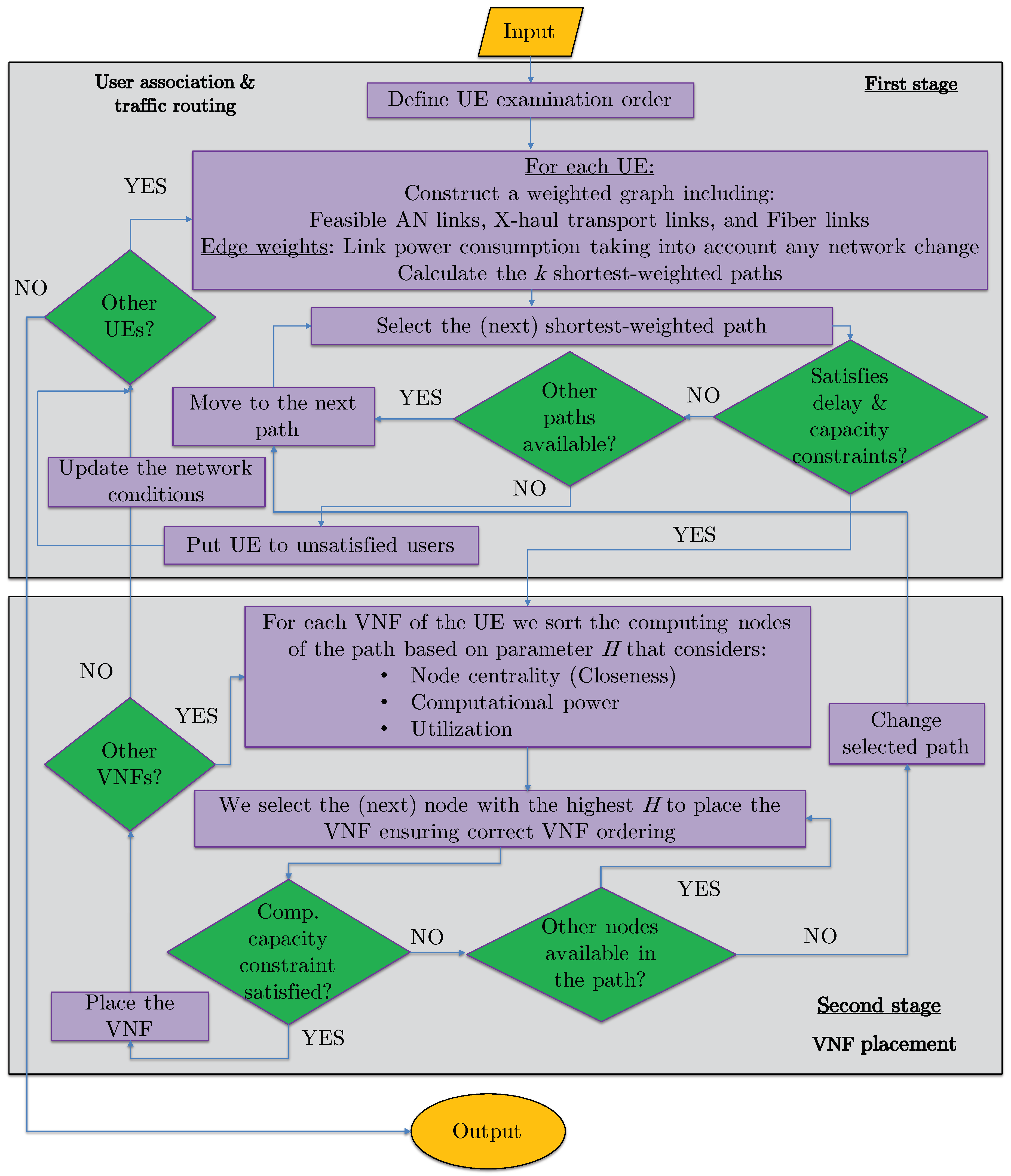
3. Proposed Energy-Efficient Vnf Placement, Traffic Routing, and User Association (Hero)

Our proposed Heuristic for Energy-efficient VNF placement, traffic Routing, and user assOciation (HERO) aims to maximize the network energy efficiency while ensuring low UE blocking probability. HERO consists of two stages, as shown in Figure 3. In the first stage, the traffic path is selected (i.e., user association and routing is performed), while in the second stage VNF placement takes place, ensuring correct VNF ordering.
Initially, to ensure a high UE acceptance ratio, the UEs are sorted based on their service demands, giving priority to the UEs with the most delay-intolerant services. For UEs with the same delay requirements, priority is given to the UEs with higher rate demands. Then, for each UE, a weighted graph is constructed from the service traffic source to the UE with all feasible links and their respective power consumption acting as weights. HERO calculates the k shortest-weighted paths and starts with the first, as long as it satisfies the delay and link capacity constraints, taking into account the decisions for the already examined users. Otherwise, the next path is selected until either a path that satisfies all constraints is found or there are no other paths. In the latter case, the UE is blocked and HERO proceeds with the next as long as there is one.
After a valid path is found for the current UE, HERO proceeds to the second stage, where the UE VNFs are being placed. To that end, for each VNF, following the order of the UE SFC, a list is constructed with all the available computational nodes based on a parameter, denoted by H. This parameter is equal to the sum of the normalized node centrality (closeness), the normalized node computational capabilities ( c y ), and the node CPU utilization. The latter is equal to (a) 1 when the studied VNF can be placed in the examined node without initiating a new VNF instance, (b) 0.1 when there is enough computational capacity to host the studied VNF in the examined node, but a new VNF instance is required, and (c) 0 otherwise. Subsequently, the node with the highest H for the selected VNF is selected, as long as it has sufficient computational resources to host it. Otherwise, the node with the next highest H is selected, until either the VNF is placed or there is no other node to examine in the selected path. In the latter case, the algorithm returns to stage 1 and the next path out of the k calculated is examined. The process is repeated for the new path until either all VNFs of the UE are placed or there is no other path to study and the UE is blocked. In the case where all UE VNFs are placed, the network conditions are updated, and the algorithm proceeds to the next UE. The aforementioned steps are repeated until all UEs are examined.

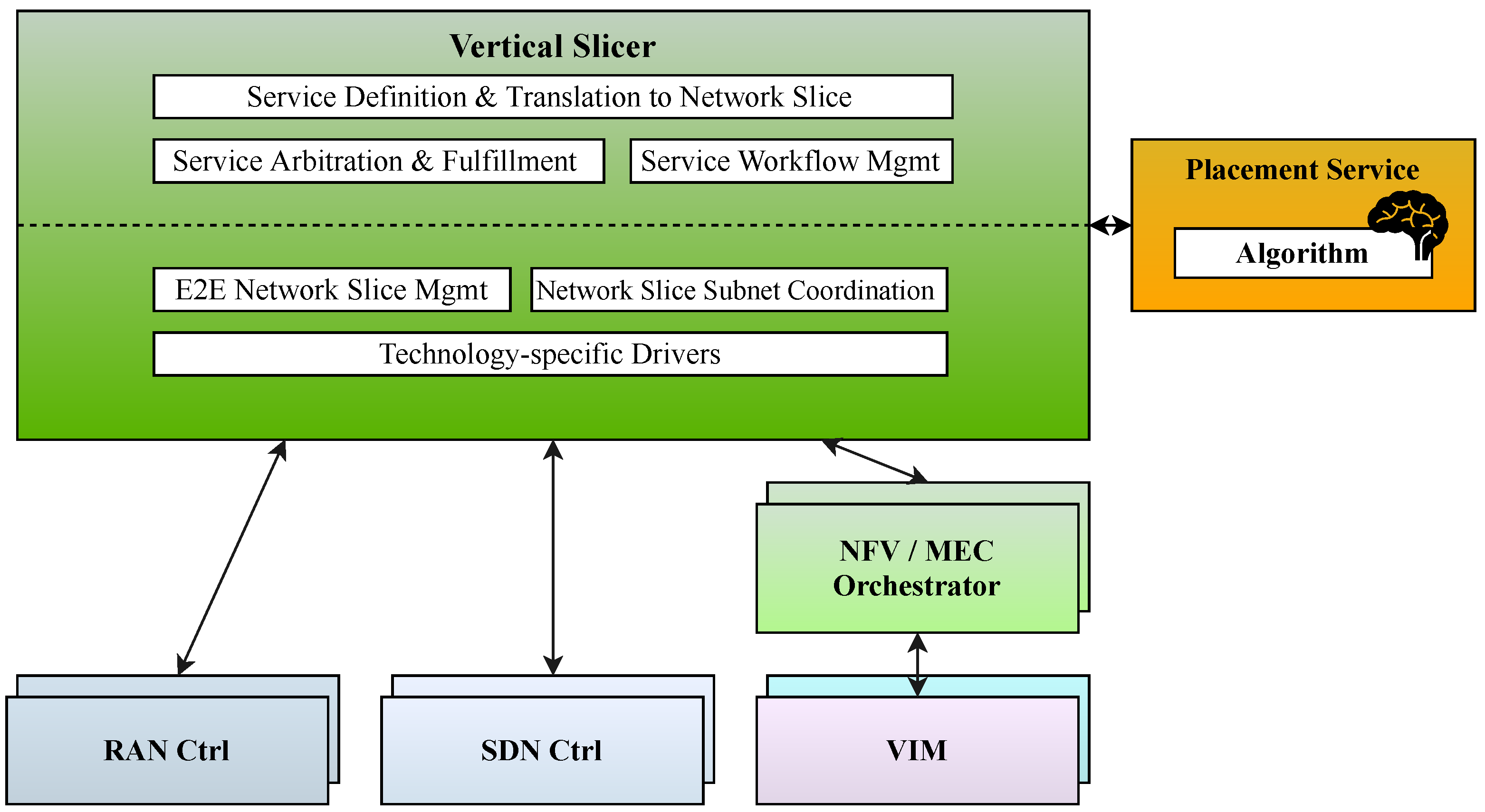
4. Interaction with Orchestration Framework

The proposed Orchestration Framework, whose high-level architecture is depicted in Figure 4, is based on the Vertical Slicer prototype in [31]. The Orchestration Framework aims at integrating and coordinating technology-specific platforms (e.g., ETSI Open Source MANO, SDN Controllers, O-RAN, etc.) to achieve the automated orchestration of E2E Network Slices, including the joint provisioning and configuration of heterogeneous resources, while considering the full chains of virtual functions associated with both mobile connectivity and application logic. The Vertical Slicer follows a service-driven approach: the high-level requirements provided by the Service Provider (e.g., number of expected UEs, Ultra-High Definition (UHD) streaming type) are dynamically mapped into performance requirements at the infrastructure layer in order to determine the characteristics of the E2E Network Slice in terms of mobile connectivity (e.g., downlink throughput) and the actual composition of the overall SFC (i.e., including network and application virtual functions) along with the dimension of its included components.
In terms of E2E Network Slice modelling, the Vertical Slicer implements a Network Slice Template where each SFC is split into three different Network Slice Subnets which specify, respectively, the deployment characteristics for the RAN, the core, and the Vertical service. The proposed modelling enhances the 3rd Generation Partnership Project (3GPP) Network Slice Network Resource Model [32] by integrating the Vertical services’ components. In addition, the Vertical Slicer also builds an overview of the needed connectivity services to be established over the transport network to fulfil the SFC.
In the orchestration and provisioning of the needed resources, the Orchestration Framework encompasses the resource allocation algorithm proposed in this paper. Specifically, when the Orchestration Framework receives a request for instantiating a service, the automated translation mechanism implemented at the Vertical Slicer determines the performance requirements and the SFC to be orchestrated. Then, the Vertical Slicer triggers a Placement Service, which calls the proposed algorithm, and provides as inputs both the service requirements and the SFC. The Placement Service takes decisions about network paths to be established at the data-plane and the placement of the different components in the SFC. The result of the computation is returned to the Vertical Slicer, which proceeds with the orchestration and configuration of the needed resources, in particular, by triggering and coordinating the target technology-specific platforms: NFV/MEC Orchestrators for VNFs’ LCM and SDN Controllers for the management and control of the data-plane. Once the service and the corresponding E2E Network Slice are properly instantiated and configured, the Vertical Slicer continues coordinating the overall LCM, interacting as needed with the technology-specific platforms for executing orchestration procedures.

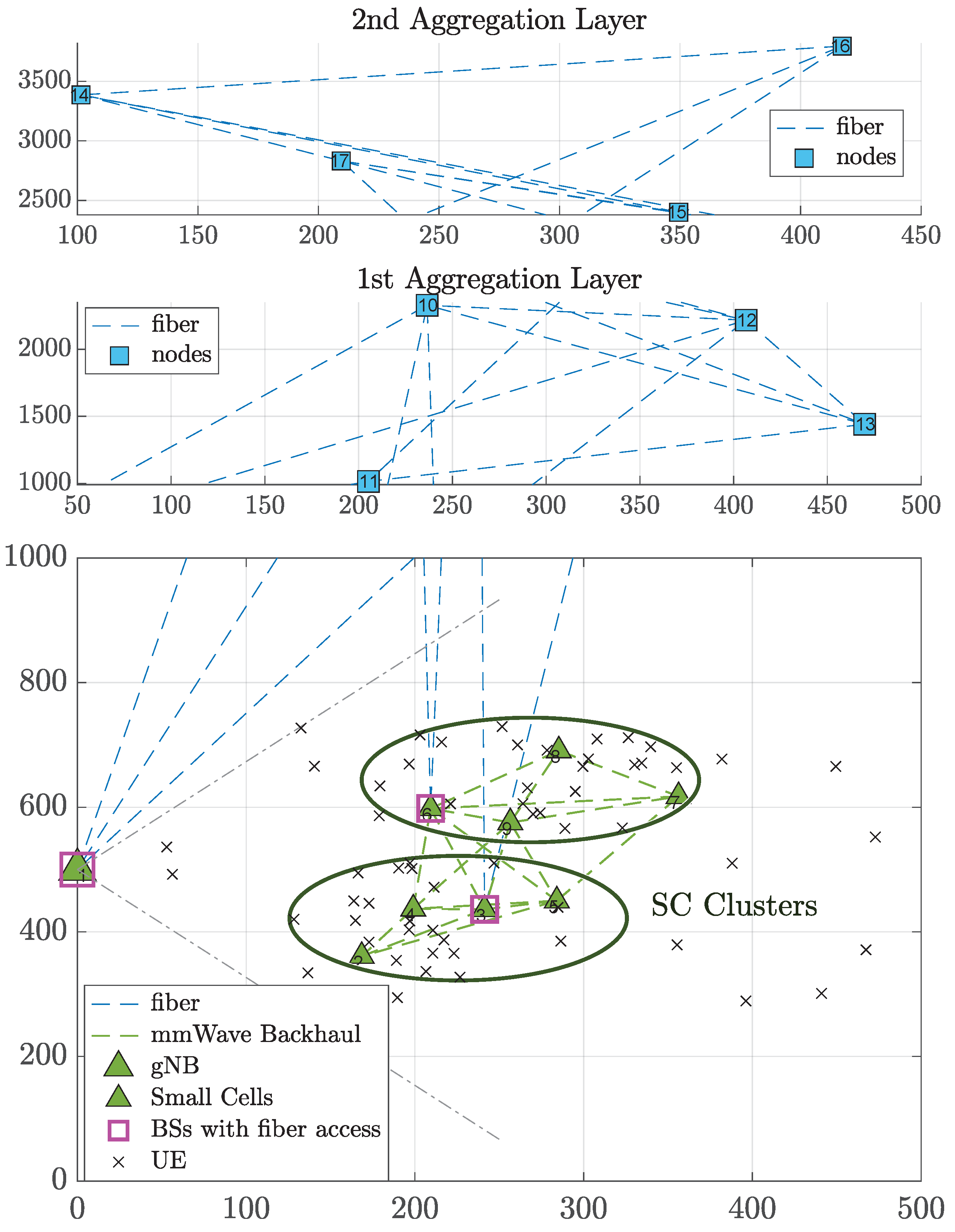
5. Evaluation Methodology and Simulation Scenarios

In our work, the heuristics were developed in MATLAB, while IBM CPLEX [33] was used to compute the optimal solution of the MILP described in Section 2.1. The simulation scenarios considered a gNB sector area of 500 m radius overlaid with two SC clusters [25], as shown in Figure 5. Each cluster contained four possible SCs, which were randomly and uniformly placed in an 100-m-radius from the cluster centers. The minimum allowable distances are given in [25]. A subset of BSs, namely one SC (randomly selected) per cluster and the gNB, was assumed to have fiber access to the aggregation network. mmWave X-haul links could be deployed among BSs as long as their distance was lower than 200 m. The aggregation network consisted of two layers each one comprising four possible node positions, as shown in Figure 5. The aggregation layer nodes were connected among them and with the BSs via fiber so that there was no disconnected node. Hotspot UE traffic was also assumed [25].
We considered five different SFCs containing ordered combinations of the following VNFs: NAT (Network Address Translation), FW (Firewall), TM (Traffic Monitor), WOC (WAN Optimization Controller), IDPS (Intrusion Detection Prevention System), and VOC (Video Optimization Controller). For each SFC, the corresponding ordered VNF combination, data rate demand (uniformly distributed in the provided set), E2E delay requirement and share of the total SFC requests, are shown in Table 2. The data processing capacity as well as the GFLOPS requirement of each VNF type are given in Table 3. For a given number of UEs, we ran 10 different scenarios, with five different UE distribution snapshots each.
We assumed 100 RBs allocated per gNB or SC (corresponding to μ = 0 in 5G numerology). The operating frequency of the gNB and SCs was 2 GHz, assuming orthogonal channels between the gNB and the SCs. However, the SCs of different clusters could interfere with each other. The mmWave X-haul links operated at 60 GHz, with 200 MHz channel bandwidth. For the AN and the mmWave links, we employed the link budget equation and related parameter values of [25]. The number of CPU cores was equal to 8, 24, and 48 for each node at the MEC, 1st, and 2nd Aggregation layers, respectively. Parameter P y ( C P U , m ) was selected randomly from the set {55, 70} for the MEC nodes, from {150, 220} for the 1st Aggregation Layer and from {200, 278} for the 2nd Aggregation Layer nodes, while the idle power was assumed to be equal to 10% of the assigned maximum power values. Each fiber link had a capacity of 10 Gbps, while the rest of the simulation parameters are summarized in Table 4.
The optimal solution and the proposed heuristic (HERO) were compared with the following SoA algorithms [15]:
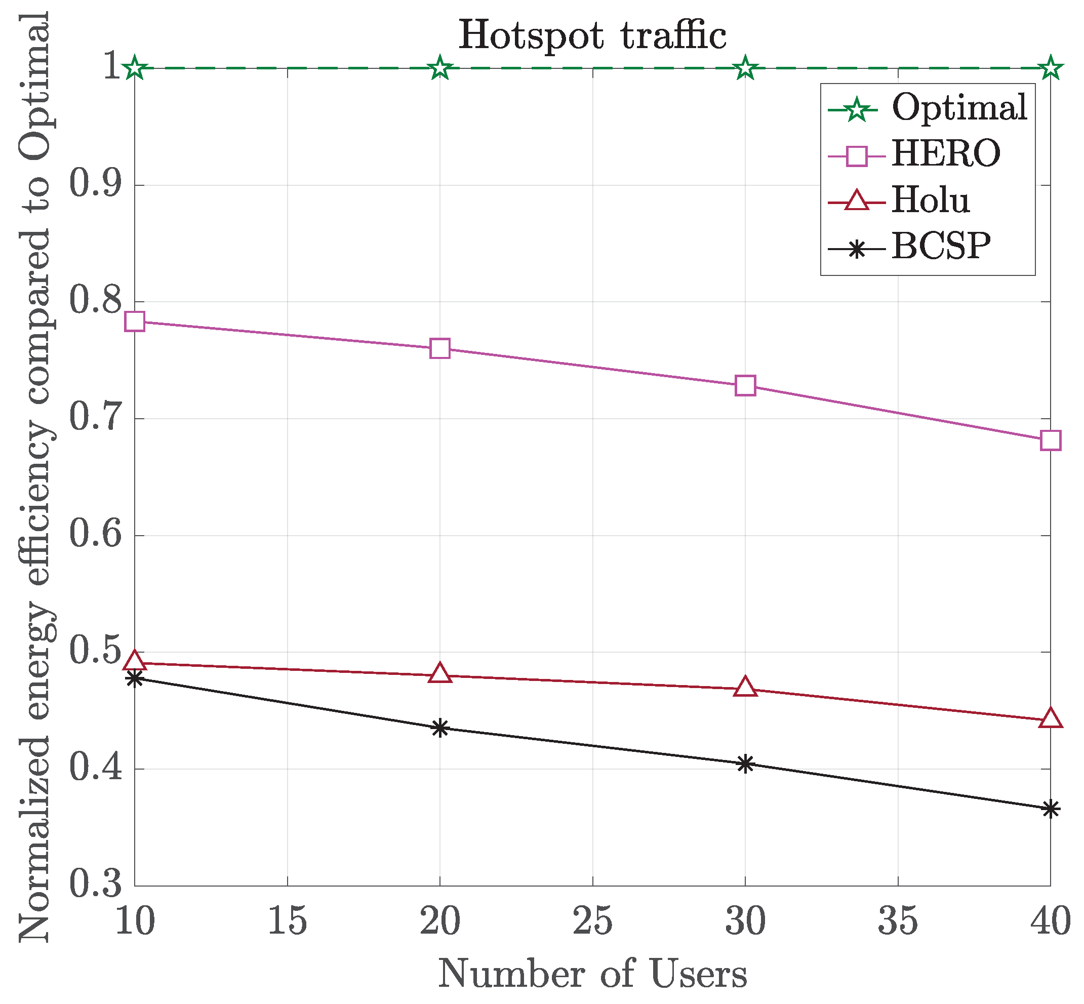
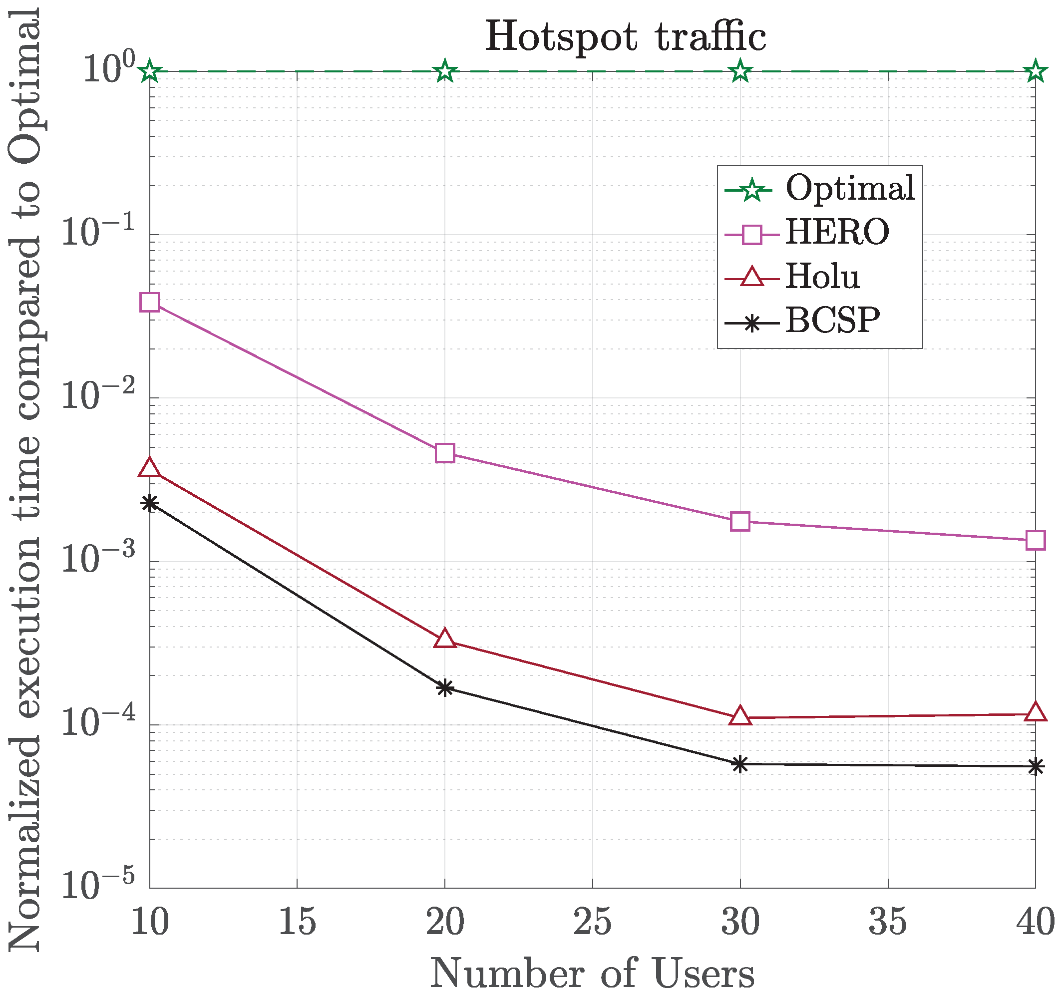
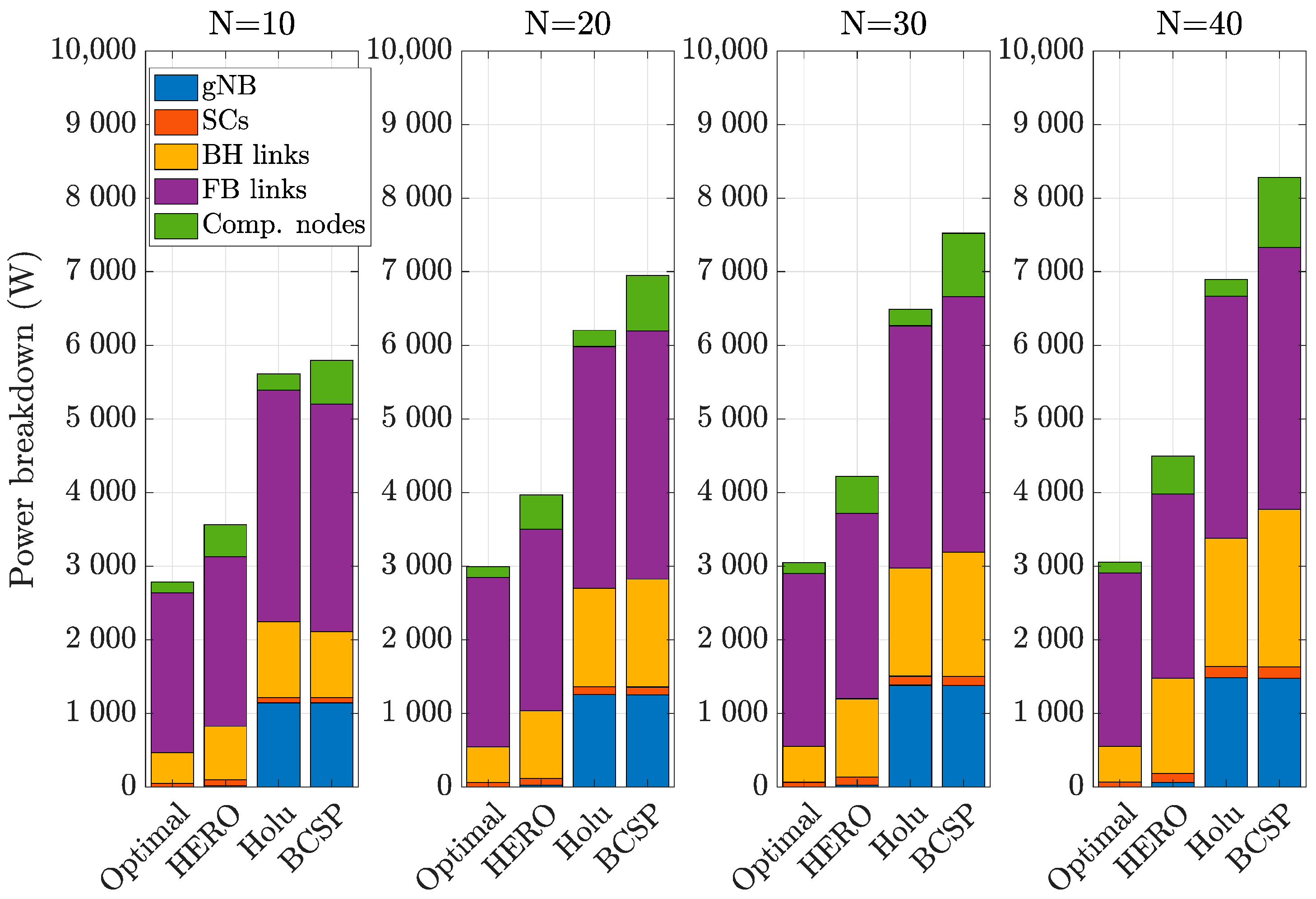
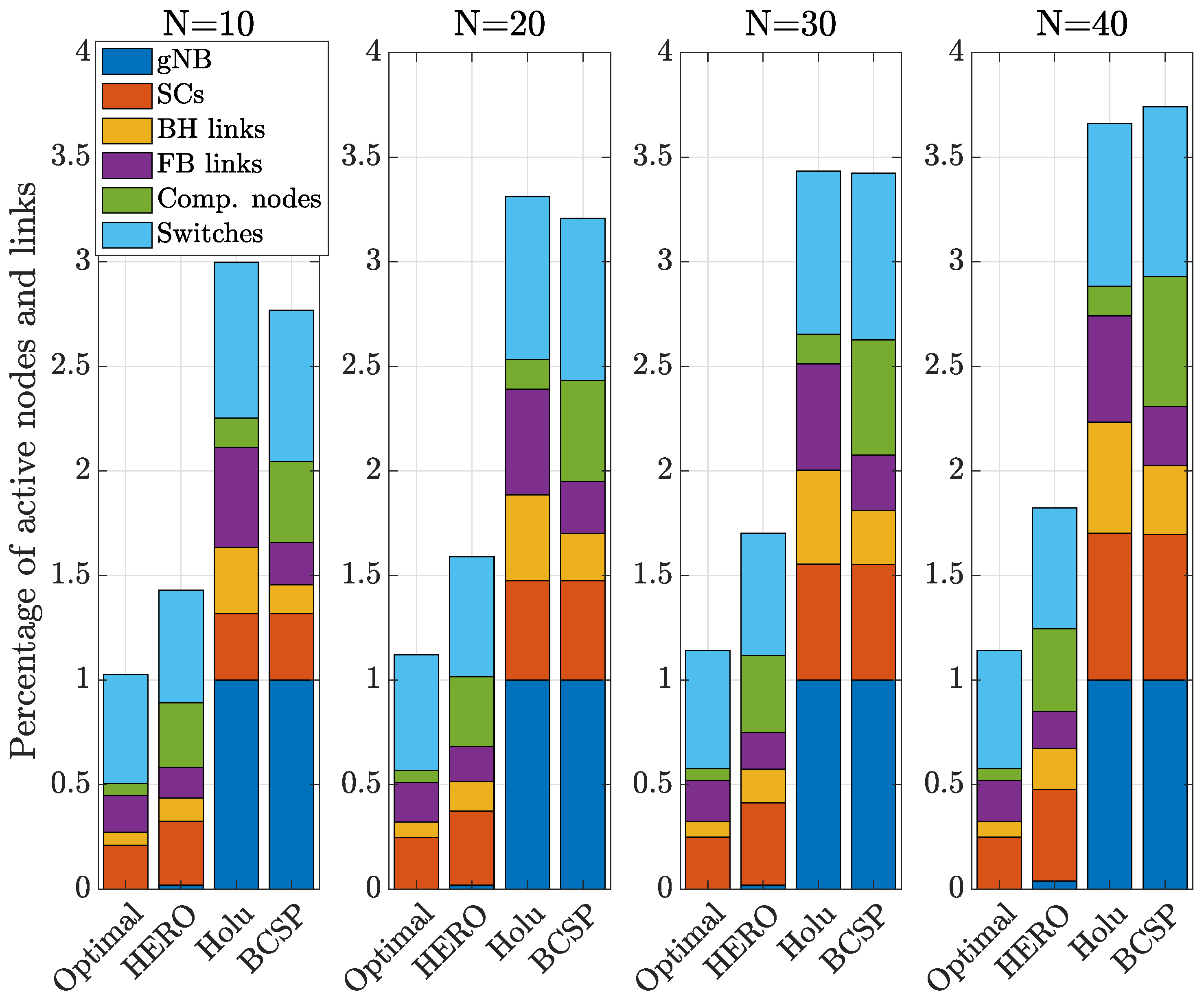
  • Holu: This algorithm first performed the VNF placement based on the node centrality (closeness) and the CPU utilization of computing nodes and then decided upon traffic routing targeting the minimization of power consumption, while satisfying the E2E service delay constraint.
  • BCSP: It considered node centrality (betweeness) for the VNF placement and the shortest-path in terms of delay for routing, while meeting the E2E service delay constraint.
Given that both reference algorithms did not handle user association, we employed the default user association criterion for both, i.e., the UEs were connected to the BSs based on the highest received signal-to-interference-plus-noise ratio (SINR), and consequently, lowest number of required RBs. In addition, for a fair comparison, their UE examination order was selected to be the same as HERO.

6. Simulation Results and Discussion

In Figure 6 and Figure 7, we show the normalized w.r.t. the Optimal solution of (17) energy efficiency (in bits/Joule) and computational time (in logarithmic scale), respectively, for all algorithms and different number of UEs. As can be seen, HERO provided a very good tradeoff between energy efficiency and complexity compared to the other approaches, achieving up to 78% of the Optimal value, with up to 742 times lower complexity. All algorithms had a 100% user acceptance ratio in all cases, except for BCSP which achieved 96% for N = 20, 93% for N = 40, and 91% for N = 40. This is due to the fact that in BCSP the CPU utilization of the computing nodes was not taken into account, resulting in less efficient VNF placement, which under higher traffic load could lead to a few UEs being blocked. The inefficiency of BCSP’s VNF placement is also shown in Figure 8, where the power break down of all algorithms for different number of UEs per gNB sector area is presented. As shown, inefficient BCSP VNF placement led to a higher number of deployed computational nodes, and thus, higher power consumption.
Compared to Holu and BCSP, HERO achieved up to 60% and 86% higher energy efficiency, respectively, while keeping the complexity low, as shown in Figure 7. This is due to the fact that HERO additionally considered user association as part of the optimization problem leading to higher flexibility at the expense of a little higher complexity. On the other hand, in both Holu and BCSP, the serving BSs were already decided (based on the best SINR criterion) and then the optimal VNF placement and traffic routing from the UE traffic source to its serving BS were performed. This is also demonstrated in Figure 8, where the Optimal and HERO did not deploy the gNB in any case but used SCs as serving BSs (in contrast to Holu and BCSP), hence, leading to much lower power consumption. We also observed that the power consumption of the Optimal and HERO were scaling better than the SoA with increasing load (HERO still achieved 68% of the Optimal energy efficiency value when N = 40).
To further prove the improved performance of the proposed solutions (Optimal and HERO), we show in Figure 9, the percentage of active nodes and links for all algorithms for different number of UEs. As can be observed, Holu and BCSP, which did not optimize user association, kept the gNB always active, thus resulting in much higher power consumption, as shown in Figure 8. In addition, in Holu and BCSP, the number of active SCs, increased at a much higher rate with increasing load compared to the proposed approaches, which proves the scalability in terms of energy efficiency of the proposed solutions unlike the SoA. Compared to Holu, HERO activated fewer BH and FB links, and consequently fewer switches at the expense, however, of a higher number of active computational nodes. This is due to the fact that, in the considered scenario, which, however, was an accurate representation of actual networks of this type, the fiber links and switches had much higher energy impact ( P i d l e ( s w ) = 315 W) compared to the computational nodes, so that more efficient user association and routing had a higher impact on the overall performance compared to the VNF placement. As a result, Holu, which gave higher priority to VNF placement at the expense of traffic routing efficiency, while not taking user association into account at all, resulted, as already shown, in poorer overall performance. It is worth noting, however, that the proposed solutions are independent of the power consumption values, since the latter constitute the algorithms’s input, and thus, different values could lead to different results always targeting high energy efficiency. As a final remark, the performance gains of the proposed algorithms justify the motivation of our work that user association, VNF placement, and traffic routing should be jointly considered to guarantee true optimal E2E network performance.

7. Conclusions

In this paper, we studied the joint VNF placement, user association, and traffic routing in B5G networks targeting energy efficiency maximization, while ensuring a high UE acceptance ratio. We modeled the aforementioned problem as a MILP with minimal assumptions, which captured all characteristics of the employed technologies, resource, and service types as well as their constraints and power consumption. To tackle the prohibitive complexity of the studied problem, we proposed HERO, an energy-efficient resource planning heuristic, which was shown to significantly outperform the SoA, while achieving up to 78% of the optimal value, with up to 742 times lower complexity. Finally, we described the Orchestration Framework that is responsible for the dynamic and automated orchestration of Vertical-driven services in tailored E2E Network Slices, and explained how such a framework is assisted by the proposed algorithms, which jointly compute the optimal allocation of both network and compute resources across the radio, core, and transport network segments.
Although the proposed formulation and heuristic algorithm can be extended to also handle service requests dynamically arriving in time (i.e., they can be used to implement an online joint computational and communications resource allocation policy), the computational complexity of the heuristic may still be too high to properly adapt to the small time scale of request arrivals. To this end, in the future, we plan to explore learning-based techniques (inspired from approximate reinforcement learning) to construct low-complexity online energy-efficient resource allocation algorithms.

Author Contributions

Conceptualization, M.G. and A.M.; architecture design, F.M. and G.L.; methodology, A.M. and M.G.; prototype implementation, L.L.; validation, A.M. and M.G.; formal analysis, M.G.; resources, G.K.; writing—original draft preparation, M.G. and A.M.; writing—review and editing, G.K., N.P. and F.M.; visualization, A.M.; supervision, N.P. and N.C.; project administration, G.K. and F.M.; funding acquisition, G.K. and N.C. All authors have read and agreed to the published version of the manuscript.

Funding

This work was funded by H2020 5G-COMPLETE (GA 871900).

Institutional Review Board Statement

Not applicable.

Informed Consent Statement

Not applicable.

Data Availability Statement

No new data were created or analyzed in this study.

Conflicts of Interest

The authors declare no conflict of interest. The funders had no role in the design of the study; in the collection, analyses, or interpretation of data; in the writing of the manuscript, or in the decision to publish the results.

Abbreviations

The following abbreviations are used in this manuscript:
3GPP3rd Generation Partnership Project
5GFifth Generation
5G-NR5G-New Radio
5G-PPP5G Infrastructure Public Private Partnership
6GSixth Generation
B5GBeyond Fifth Generation
BSBase Station
ANAccess Network
CAPEXCapital Expenditure
CPUCentral Processing Unit
C-RANCentralized-Radio Access Network
DLDownlink
E2EEnd-to-end
eMBBEnhanced Mobile Broadband
ETSIEuropean Telecommunications Standards Institute
FPGAField Programmable Gate Array
FWFirewall
gNBgNodeB
GPUGraphics Processing Unit
ICTInformation and Communications Technology
IDPSIntrusion Detection/Prevention System
LCMLifecycle Management
MANOManagement and Orchestration
MECMulti-Access Edge Computing
MILPMixed Integer Linear Program
mMTCMassive Machine Type Communication
NATNetwork Address Translation
NFVNetwork Function Virtualization
OPEXOperational Expenditure
OSIOpen System Interconnection
QoSQuality of Service
RANRadio Access Network
RBResource Block
RFRadio Frequency
SINRSignal to Interference plus Noise Ratio
State-of-the-ArtSoA
SCSmall Cell
SDNSoftware Defined Networking
SDOStandards Developing Organization
SFCService Function Chain
TMTraffic Monitor
uRLLCUltra Reliable Low Latency Communication
UEUser Equipment
UHDUltra-High Definition
VMVirtual Machine
VNFVirtual Network Function
VOCVideo Optimization Controller
WOCWAN Optimization Controller

References

  1. Ali, J.; Roh, B.H.; Lee, S. QoS improvement with an optimum controller selection for software-defined networks. PLoS ONE 2019, 14, e0217631. [Google Scholar] [CrossRef] [PubMed]
  2. Ali, J.; Roh, B.H. Quality of Service improvement with optimal software-defined networking controller and control plane clustering. Comput. Mater. Contin. 2021, 67, 849–875. [Google Scholar] [CrossRef]
  3. Barakabitze, A.; Ahmad, A.; Mijumbi, R.; Hines, A. 5G network slicing using SDN and NFV: A survey of taxonomy, architectures and future challenges. Comput. Netw. 2020, 167, 106984. [Google Scholar] [CrossRef]
  4. Abbas, N.; Zhang, Y.; Taherkordi, A.; Skeie, T. Mobile Edge Computing: A survey. IEEE Internet Things J. 2018, 5, 450–465. [Google Scholar] [CrossRef] [Green Version]
  5. Tang, L.; Yang, H.; Ma, R.; Hu, L.; Wang, W.; Chen, Q. Queue-aware dynamic placement of virtual network functions in 5G access network. IEEE Access 2018, 6, 44291–44305. [Google Scholar] [CrossRef]
  6. Laghrissi, A.; Taleb, T. A survey on the placement of virtual resources and Virtual Network Functions. IEEE Commun. Surv. Tutor. 2019, 1, 1409–1434. [Google Scholar] [CrossRef] [Green Version]
  7. Liu, J.; Lu, W.; Zhou, F.; Lu, P.; Zhu, Z. On dynamic Service Function Chain deployment and readjustment. IEEE Trans. Netw. Serv. Manag. 2017, 14, 543–553. [Google Scholar] [CrossRef]
  8. Dong, L.; da Fonseca, N.; Zhu, Z. Application-Driven provisioning of Service Function Chains over heterogeneous NFV platforms. IEEE Trans. Netw. Serv. Manag. 2021, 18, 3037–3048. [Google Scholar] [CrossRef]
  9. Cao, H.; Du, J.; Zhao, H.; Luo, D.; Kumar, N.; Yang, L.; Yu, F. Resource-Ability assisted Service Function Chain embedding and scheduling for 6G networks With virtualization. IEEE Trans. Veh. Technol. 2021, 70, 3846–3859. [Google Scholar] [CrossRef]
  10. Cudak, M.; Ghosh, A.; Ghosh, A.; Andrews, J. Integrated access and backhaul: A key enabler for 5G millimeter-wave deployments. IEEE Commun. Mag. 2021, 59, 88–94. [Google Scholar] [CrossRef]
  11. Ghribi, C.; Mechtri, M.; Zeghlache, D. A dynamic programming algorithm for joint VNF placement and chaining. In Proceedings of the 2016 ACM Workshop on Cloud-Assisted Networking, Irvine, CA, USA, 12 December 2016. [Google Scholar]
  12. Ma, Y.; Liang, W.; Huang, M.; Xu, W.; Guo, S. Virtual Network Function service provisioning in MEC via trading off the usages between computing and communication resources. (early access). IEEE Trans. Cloud Comput. 2020. [Google Scholar] [CrossRef]
  13. Soualah, O.; Mechtri, M.; Ghribi, C.; Zeghlache, D. Energy efficient algorithm for VNF placement and chaining. In Proceedings of the 2017 17th IEEE/ACM International Symposium on Cluster, Cloud and Grid Computing (CCGRID), Madrid, Spain, 14–17 May 2017. [Google Scholar]
  14. Ayoubi, S.; Sebbah, S.; Assi, C. A logic-based Benders decomposition approach for the VNF assignment problem. IEEE Trans. Cloud Comput. 2019, 7, 894–906. [Google Scholar] [CrossRef]
  15. Varasteh, A.; Madiwalar, B.; van Bemten, A.; Kellerer, W.; Mas–Machuca, C. Holu: Power-aware and delay-constrained VNF placement and chaining. IEEE Trans. Netw. Serv. Manag. 2021, 18, 1524–1539. [Google Scholar] [CrossRef]
  16. Tajiki, M.; Salsano, S.; Chiaraviglio, L.; Shojafar, M.; Akbari, B. Joint energy efficient and QoS-aware path allocation and VNF placement for Service Function Chaining. IEEE Trans. Netw. Serv. Manag. 2019, 16, 374–388. [Google Scholar] [CrossRef] [Green Version]
  17. Dietrich, D.; Papagianni, C.; Papadimitriou, P.; Baras, J. Network function placement on virtualized cellular cores. In Proceedings of the 2017 9th International Conference on Communication Systems and Networks (COMSNETS), Bangalore, India, 4–8 January 2017. [Google Scholar]
  18. Yang, S.; Li, F.; Trajanovski, S.; Chen, X.; Wang, Y.; Fu, X. Delay-aware Virtual Network Function placement and routing in edge clouds. IEEE Trans. Mobile Comput. 2021, 20, 445–459. [Google Scholar] [CrossRef] [Green Version]
  19. Spinelli, F.; Mancuso, V. Toward enabled industrial verticals in 5G: A survey on MEC-based approaches to provisioning and flexibility. IEEE Commun. Surv. Tutor. 2021, 23, 596–630. [Google Scholar] [CrossRef]
  20. Open Source MANO. 2021. Available online: https://osm.etsi.org/ (accessed on 7 October 2021).
  21. O-RAN Alliance. 2021. Available online: https://www.o-ran.org/ (accessed on 7 October 2021).
  22. Casetti, C.; Chiasserini, C.; Martín-Pérez, J.; Molner, N.; Deiss, T. The Vertical Slicer: Verticals’ Entry Point to 5G Networks. In Proceedings of the 27th European Conference on Networks and Communications (EuCNC 2018), Ljubljana, Slovenia, 18–21 June 2018. [Google Scholar]
  23. Perez, M.G.; Perez, G.M.; Giardina, P.; Bernini, G.; Neves, P.; Alcaraz-Calero, J.; Wang, Q.; Koutsopoulos, K. Self-Organizing Capabilities in 5G Networks: NFV & SDN Coordination in a Complex Use Case. In Proceedings of the 27th European Conference on Networks and Communications (EuCNC 2018), Ljubljana, Slovenia, 18–21 June 2018. [Google Scholar]
  24. Khalili, H.; Papageorgiou, A.; Siddiqui, M.; Meixner, C.C.; Carrozzo, G.; Nejabati, R.; Simeonidou, D. Network Slicing-aware NFV Orchestration for 5G Service Platforms. In Proceedings of the 28th European Conference on Networks and Communications (EuCNC 2019), Valencia, Spain, 18–21 June 2019. [Google Scholar]
  25. Mesodiakaki, A.; Zola, E.; Santos, R.; Kassler, A. Optimal user association, backhaul routing and switching off in 5G heterogeneous networks with mesh millimeter wave backhaul links. Ad Hoc Netw. 2018, 78, 99–114. [Google Scholar] [CrossRef]
  26. ETSI ES 203 228: Environmental Engineering (EE): Assessment of Mobile Network Energy Efficiency, November 2020. v.1.3.1. Available online: https://www.etsi.org/deliver/etsi_es/203200_203299/203228/01.03.01_60/es_203228v010301p.pdf (accessed on 7 October 2021).
  27. ETSI EN 303 471: Energy Efficiency Measurement Methodology and Metrics for Network Function Virtualisation (NFV), January 2019. v.1.1.1. Available online: https://www.etsi.org/deliver/etsi_en/303400_303499/303471/01.01.01_60/en_303471v010101p.pdf (accessed on 7 October 2021).
  28. Li, X.; Garcia-Saavedra, A.; Costa-Perez, X.; Bernardos, C.; Guimaraes, C.; Antevski, K.; Mangues-Bafalluy, J.; Baranda, J.; Zeydan, E.; Corujo, D.; et al. 5Growth: An End-to-End Service Platform for Automated Deployment and Management of Vertical Services over 5G Networks. IEEE Commun. Mag. 2012, 59, 84–89. [Google Scholar] [CrossRef]
  29. Gatzianas, M.; Mesodiakaki, A.; Kalfas, G.; Pleros, N. Energy-efficient joint computational and network resource planning in Beyond 5G networks. Proc. IEEE Globecom. 2021. to appear. [Google Scholar]
  30. Boyd, S.; Vandenberghe, L. Convex Optimization; Cambridge University Press: Cambridge, UK, 2004. [Google Scholar]
  31. Vertical Slicer. Available online: https://github.com/nextworks-it/slicer (accessed on 7 October 2021).
  32. TR 28.541: Management and Orchestration; 5G Network Resource Model (NRM); Stage 2 and Stage 3 (Rel. 17), 2020. v. 17.0.0. Available online: https://www.3gpp.org/ftp//Specs/archive/28_series/28.541/28541-h01.zip (accessed on 7 October 2021).
  33. ILOG CPLEX Optimization Studio. 2020. Available online: https://www.ibm.com/products/ilog-cplex-optimization-studio (accessed on 7 October 2021).
  34. Heddeghem, W.V.; Idzikowski, F.; Vereecken, W.; Colle, D.; Pickavet, M.; Demeester, P. Power consumption modeling in optical multilayer networks. Photon. Netw. Commun. 2012, 24, 86–102. [Google Scholar] [CrossRef] [Green Version]
Figure 1. Mobile network of heterogeneous communication and computation nodes along with middlebox functionality offered by deployed VNFs. Dashed color lines indicate 2 illustrative E2E paths selected for 2 highlighted UEs.
Applsci 11 10547 g001
Figure 2. Embedding of virtual network (bottom part) into the physical network (top part). For illustration, 2 distinct SFCs are shown (in green and red) corresponding to 2 different UE requests, and each SFC is described by its own virtual network. G ( ρ 1 ) (green color) contains 6 virtual nodes and 5 virtual edges, whereas G ( ρ 2 ) contains 5 virtual nodes and 4 virtual edges. The virtual nodes will be mapped to actual physical nodes, while the virtual edges will be mapped to actual paths in the physical network.
Applsci 11 10547 g002
Figure 3. Flowchart of the proposed energy-efficient VNF placement, traffic routing, and user association algorithm (HERO).
Applsci 11 10547 g003
Figure 4. Orchestration Framework high-level architecture.
Applsci 11 10547 g004
Figure 5. Simulation scenario example topology.
Applsci 11 10547 g005
Figure 6. Energy efficiency (bits/Joule) of all algorithms for different numbers of UEs per gNB area.
Applsci 11 10547 g006
Figure 7. Execution time (s) in logarithmic scale of all algorithms for different numbers of UEs per gNB area.
Applsci 11 10547 g007
Figure 8. Power (W) breakdown of all algorithms for low traffic (N = 10) and high traffic (N = 40).
Applsci 11 10547 g008
Figure 9. Percentage of active nodes and links of all algorithms for different numbers of UEs per gNB area.
Applsci 11 10547 g009
Table 1. List of Symbols and Notations.
SymbolInterpretationNotation for Element
(In Case of Sets)
SymbolInterpretationNotation for Element
(In Case of Sets)
Input parameters
V Set of network nodes
(excluding mobile users)
u ,   v V s w Set of nodes
equipped with switch
u ,   v
E Set of network links
(excluding access links)
e = ( u ,   v ) J Set of UEsj
E f i , E w l Set of fiber (resp. wireless)
non-access links
( u ,   v ) E A N Set of access links ( a ,   j )
c e Communication capacity
of link e
NA δ e Delay (i.e., transmission + propagation)
induced by link e
NA
A ( j ) Set of BSs that UE j
can connect to
a S ( a ) Set of UEs that can
be served by BS a
j
V c Set of network nodes equipped
with computational resources
y c y Amount of computational resources
available at node y
NA
F Set of available VNFs f = ( T f ,   π f ,   w f ,   τ f ) where T f : VNF id, π f : VNF data processing capacity, w f : amount of CPU resources required by VNF, τ f : delay induced by VNF processing
C Set of available SFCs ρ = f d u m 1 ,   f 1 ( ρ ) , ,   f N ρ ( ρ ) ,   f d u m 2
R ρ Set of VNFs
comprising
SFC ρ
f G ( ρ ) Virtual directed graph
describing SFC via virtual node
set V ( ρ ) and virtual edge set E ( ρ )
NA
Q Set of requests by UEs q = ( s q ,   r q ,   δ q ,   ρ q ) where s: source node of service request, r q : E2E requested rate,
δ q : E2E requested latency, ρ q : requested SFC
N a , j ( R B ) Number of RBs needed to be assigned by BS a to UE j to meet its requested rate
P i d l e ( s w ) Switch idle powerNA P e ( m m W , i ) Idle power of transmitter
in mmWave link e
NA
P a ( g N B , i ) Idle power of gNB aNA P a ( S C , i ) idle power of SC aNA
N R F ( m m W ) Number of RF chains used
in transmitter of mmWave link
NA N R F ( g N B ) , N R F ( S C ) Number of RF chains
used by gNB, SC
NA
Δ e ( m m W ) Slope parameter of transmitter
in mmWave link e
NA Δ a ( g N B ) , Δ a ( S C ) Slope parameter of transmitter
in gNB, SC a
NA
Decision variables
x j , a Boolean indicator of whether UE j
actually connects to BS a
ϕ y ˜ , f , q Boolean indicator of whether VNF f requested
by service q is deployed on node y ˜
θ e e , q , θ u , v e , q Boolean indicator of whether physical link
belongs to the physical path onto which the
virtual link e E ( ρ q ) is mapped for SFC r h o q
N f , y ˜ Number of instances
of VNF f
deployed on node y ˜
z n , m Boolean indicator of whether fiber link ( n , m ) actually
carries traffic in either of its directions
w e , w n , m Boolean indicator of whether fiber link e = ( n , m )
actually carries traffic from n to m
ξ y Boolean indicator of whether the computational
resources of node y are used
ψ n Boolean indicator of whether the switch at node n
is actually used to forward traffic
μ a Boolean indicator for whether
BS a serves any UEs
χ e Boolean indicator of whether wireless link
e is actually used to serve any traffic
ν a Auxiliary variable for μ a [25] σ e Auxiliary variable for χ e [25]
Table 2. SFC details [15].
TypeVNF OrderingThroughput
(Mbps)
Delay
(ms)
Share
(%)
WebNAT→FW→TM→WOC→IDPS[0.6–1]50020
VoIPNAT→FW→TM→FW→NAT[0.404–0.64]10020
StreamingNAT→FW→TM→VOC→IDPS[5–24]10039
GamingNAT→FW→VOC→WOC→IDPS[0.24–0.5]606
Ultra RT AI/MLNAT→NAT[15–25]115
Table 3. VNF details [15].
TypeNATFWTMVOCWOCIDPS
Process Capacity (Mbps)500400200578300600
GFLOPS Requirement11044055110110440
Table 4. Simulation Parameters [15,25,34].
ParameterValueParameterValueParameterValue
P i d l e ( s w ) 315 W P p o r t 7 WPacket length1.5 KB
N R F ( g N B ) 8 N R F ( S C ) 4 N R F ( m m W ) 64
Δ a ( g N B ) 4.7 Δ a ( S C ) 4 Δ e ( m m W ) 100
P a ( g N B , i ) 130 W P a ( S C , i ) 6.8 W P e ( m m W , i ) 3.9 W
Publisher’s Note: MDPI stays neutral with regard to jurisdictional claims in published maps and institutional affiliations.

