
Experimental Validation and Evaluation of a Coupled Twist-Camber Morphing Wing Concept


1
Department of Mechanical Engineering, University of Victoria, Victoria, BC V8P 5C2, Canada
2
IDMEC-Instituto Superior Técnico, 1049-001 Lisbon, Portugal
*
Author to whom correspondence should be addressed.
Appl. Sci. 2021, 11(22), 10631; https://0-doi-org.brum.beds.ac.uk/10.3390/app112210631
Submission received: 1 October 2021
/
Revised: 9 November 2021
/
Accepted: 9 November 2021
/
Published: 11 November 2021
(This article belongs to the Special Issue Smart Aircraft Morphing Technologies)
Abstract
:A morphing wing concept allowing for coupled twist-camber shape adaptation is proposed. The design is based on an optimized thickness distribution both spanwise and chordwise to be able to morph the wing sections into targeted airfoil shapes. Simultaneously, the spanwise twist is affected by the actuation. The concept provides a higher degree of control on the lift distribution which can be used for roll control, drag minimization, and active load alleviation. Static deformation and flight tests have been performed to evaluate and quantify the performance of the proposed mechanism. The ground tests include mapped actuated wing shapes, and wing mass and actuation power requirements. Roll authority, load alleviation, and aerodynamic efficiency estimates for different configurations were calculated using a lifting line theory coupled with viscous 2D airfoil data. Roll authority was estimated to be low when compared to a general aviation aircraft while the load alleviation capability was found to be high. Differences between the lift to drag ratio between the reference and morphing wing configurations are considerable. Mass and actuation energy present challenges that can be mitigated. The flight tests were used to qualitatively assess the roll control capability of the prototype, which was found to be adequate.
1. Introduction
The idea of changing the geometry of the lifting surfaces to adapt them to the flight condition is not new. Flaps and slats are examples of such changes but they are used for short flight segments due to their specific usage for take-off and landing. Morphing aircraft also follow the same idea and have been researched for more than a decade, with the main goal of improving overall flight performance. The metric usually used for assessment is fuel consumption.
The challenges presented in shape adaptation remain unanswered due to the opposing requirements of flexibility and sufficient stiffness and load-bearing capability. The usual consequences of these challenges are the potential aerodynamic benefits being overweighed by extra mass or energy penalties.
Methods for the design and modeling of morphing wings can be found in [1]. Investigations on flutter suppression in a variable span morphing wing were performed in order to determine its applicability and morphing speed in relation to the critical span length [2]. Low fidelity models were used to assess flutter instability in a camber morphing wing. Quasi-steady aerodynamics and unsteady aerodynamics were used with the quasi-steady model showing more conservative results and active camber morphing could be used for stabilization of the wing [3].
Still, within the camber morphing research, aero-structural high-fidelity optimization of an adaptive trailing edge for transonic flight predicts decreased fuel burn by more than 5% [4]. Optimum deformations for a transonic airfoil with morphing leading and trailing edges were obtained using high-fidelity aero-structural modeling, showing significant aerodynamic performance improvement [5].
Compliant leading and trailing edge mechanism design considering nonlinear large deformation based on hyper elastic structural topology optimization with a non-linear meshless method have been performed. A demonstrator was built to assess deformation capability and aerodynamic benefits [6].
Morphing droop nose devices for the high lift in regional aircraft were developed [7] and designed up to a detailed CAD model to assess functionality, installation, inspection, actuation power, and weight [8]. An adaptive shock control review on a number of shock control bumps concepts for wave drag reduction that includes conventional spoiler actuators, shape memory alloys, or pressurized elements is another type of morphing concept [9].
An example of a bioinspired morphing concept based on artificial feathers for small drones was investigated using simulation, wind tunnel measurements, and outdoor flights [10]. Composite lattice-based cellular structures have been proposed to tailor the stiffness of a structure with low-density modular building blocks and demonstrated with a variable twist wing [11]. Corrugated morphing skins were proposed to tackle the problem of shape change and aerodynamic load-bearing capability [12].
Morphing wing twist capability together with camber change capability in the horizontal stabilizer proved to be effective in achieving roll control and lift changes in a small unmanned aerial vehicle (UAV) [13]. Wing twist morphing capability also promises performance improvements in transport-type aircraft [14] and combat UAVs [15].
Investigations on the importance of morphing scheduling and flight condition on the actuation force and energy requirements show that these factors can be determinants of the assessment of the viability of a morphing device [16].
Not only have independent groups been investigating morphing aircraft technologies but it has also been a research field supported by collaborative research programs. The NOVEMOR project addressed novel aircraft configurations and morphing solutions for improved flight performance in the conceptual design stage [17]. The SARISTU project addressed the challenges in integrating smart and intelligent structures in commercial aircraft [18,19]. Within the scope of this project, computational and experimental models for leading edge, trailing edge, and winglet morphing were developed and served as the basis for more recent investigations on the aero-servo-elastic behavior of morphing wings including flutter analysis and dynamic stability of the morphing systems [20]. The major European collaborative programs Clean Sky 1 and 2 [21,22] also addressed morphing technologies as an important part of the European effort to reduce fuel consumption and minimize emissions in commercial aviation ranging from regional to large passenger aircraft and also for future vertical take-off and landing aircraft. An example of the research on morphing within this program is the proposed morphing winglet concept [23,24] with a fault-tolerant architecture that is intended to improve performance and alleviate wing loads in maneuver conditions.
In this paper, a prototype of a morphing wing with coupled camber-twist change capability and its testing is described. This novel concept contributes to the state-of-the-art as it explores multiple and coupled morphing concepts while also exploring multiple functions for said concepts, thus improving the competitiveness of the morphing solution when compared to conventional ones. In particular, this work explores the functionality of the concept for roll control, performance improvements, and load alleviation.
The paper is organized as follows; Firstly, the explanation on the morphing concept and wing manufacture is presented. Secondly, the ground testing procedure to determine the wing’s actuated shapes is described and estimates of roll authority, load alleviation potential, aerodynamic efficiency differences, mass and actuation energy are shown. Thirdly, a section about flight testing describes the outcome of a small flight using the morphing wing prototype. Finally, the main conclusions are highlighted.
2. Morphing Wing Concept
2.1. Design Methodology
The starting point for the implementation of the concept is the generation of a 2D airfoil morphing capability within two specified target airfoil shapes with different camber. The concept uses an open trailing edge (TE) airfoil in order to allow actuation by reduction in the distance between the upper and lower surfaces TEs. For the purpose of accomplishing camber morphing, an aero-structural optimization procedure was devised that minimized the airfoil section weight while constraining the maximum and averaged deviations from the actuated target shape with and without loading, using finite element models (FEM). The design variables describe the thickness distribution along the airfoil length that is to provide the best approximation to the target shape when actuated. Figure 1 depicts the optimization results. Further details on the 2D camber airfoil design procedure can be found in [25].
The previous methodology was further expanded to include effects of tapper in the wing platform and non-uniform actuation along the span, therefore, allowing a wider range of attainable configurations and introducing the coupling between camber and twist as another factor in the design. This time, the 2D optimization procedure was used to determine the thickness distribution for morphing wing sections with different chords and those results were used to obtain the thickness distribution of the wing skin for a particular planform shape. A second optimization step was introduced to determine the optimum wing planform shape and the actuation along the span that maximizes performance by including both the lift to drag ratio (L/D) and wing mass in the objective function.
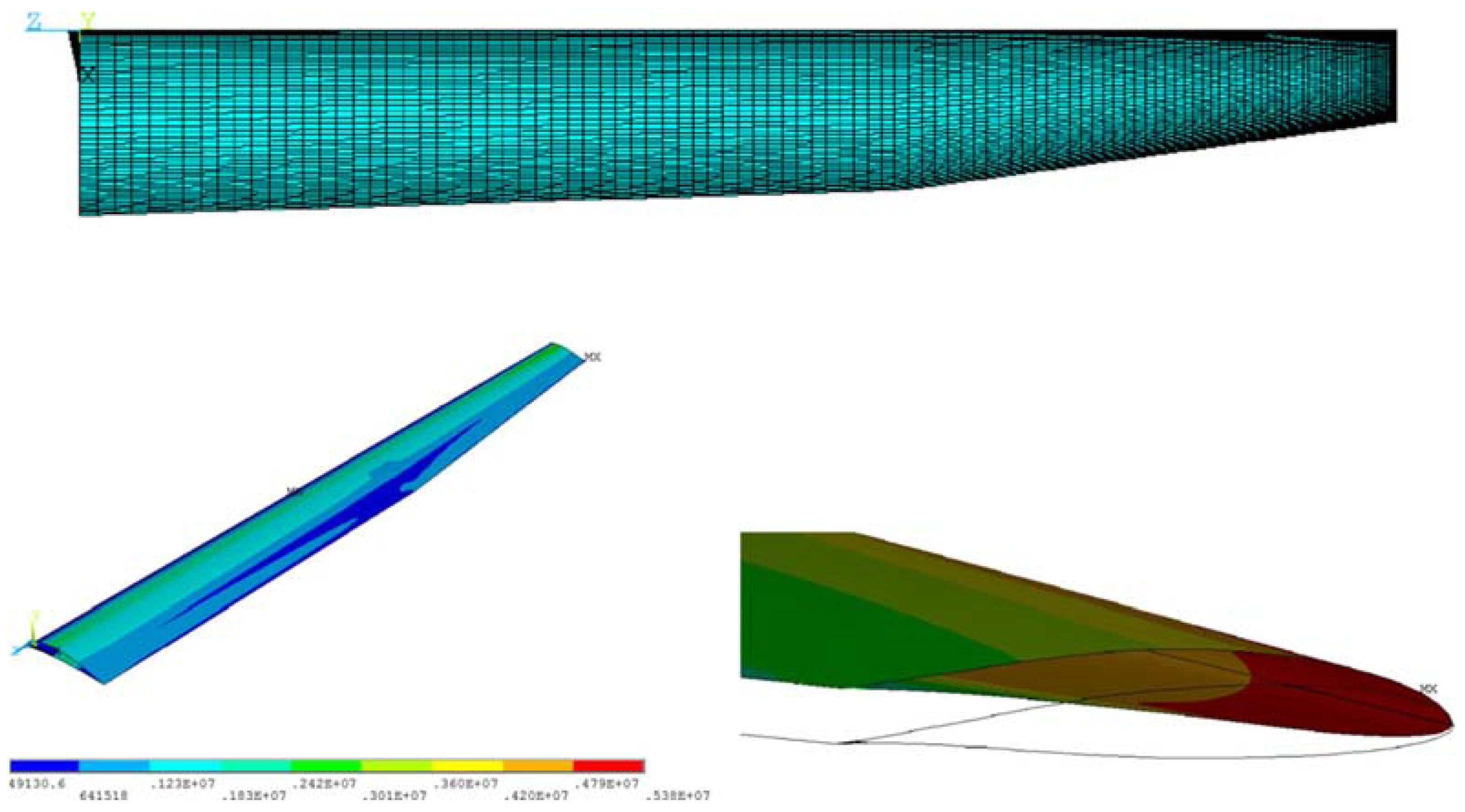
The wing twist was correlated to the actuation distribution by means of a surrogate model that was updated as FEM results are available during the optimization procedure. Figure 2 presents the data flow during the coupled twist-camber morphing wing design procedure and Figure 3 depicts the FEM and the stress and deformation results for that design. Further details about the 3D coupled camber-twist morphing wing design process can be found in [26].
Figure 4 depicts the twist-camber coupling. At the top of Figure 4, the tip airfoil was unactuated while the root section was actuated and its camber is increased. As a result, the tip of the airfoil twists down by a visible amount. At the bottom of Figure 4, the root was unactuated while the tip was actuated. The outcome was an increase in the camber of the tip airfoil while the twist was left virtually unaltered. In the middle of Figure 4, the tip airfoil is shown when the wing was completely unactuated as a reference for the other two tip airfoil positions.
The concept offers significant geometrical changes and, therefore, the potential to control the lift distribution that could be used for objectives as roll control capability, drag reduction, and load alleviation.
Several challenges must be overcome before the successful exploitation of the concept is realized. Proper manufacturing, structural soundness, mass reduction, actuation energy minimization, and morphing strategy determination are some of those challenges which are addressed next.
2.2. Wing Skin
The design generated in [26] was scaled up 1:3 resulting in a planar wing surface of 0.5 m2, an aspect ratio (AR) of 16.9, and a wingspan of 3 m. The resulting minimum skin thickness is about 0.5 mm, which made it possible to manufacture using composite materials.
The manufacturing process of the wing skin started with a manual layup of carbon fiber reinforced polymers (CFRP) molded and cured using vacuum bagging. The skin was manufactured as one piece.
The outer surface of the wing was composed of a woven carbon fiber (CF) layer with fibers oriented with and perpendicular to the spanwise direction. This layer provides handling strength and reduced torsional stiffness to facilitate actuation. On the inner surface, a unidirectional CF layer is used to increase the bending stiffness without impacting greatly the required actuation power. In between layers, four layers of paper with prescribed shapes were placed as accurately as possible to obtain an approximation to the designed thickness distribution. Each layer of paper was 0.1 mm thick, and its function wass to absorb the resin while maintaining the necessary separation between layers while curing the composite.
This manufacturing solution was penalizing in terms of structural mass. Ideally, honeycomb or foam core machined to the desired shape would allow for a significantly lighter structure, however, given the reduced thicknesses involved and the available resources, it was not possible to find an alternative solution at this time. It was also difficult to guarantee a high accuracy of the placement of the paper layers during the curing of the material since the layers could slide relative to each other and the CF layers. Nevertheless, the resulting piece still exhibited the expected behavior and was therefore deemed suitable for the following ground and flight tests as a proof of concept.
2.3. Internal and External Components
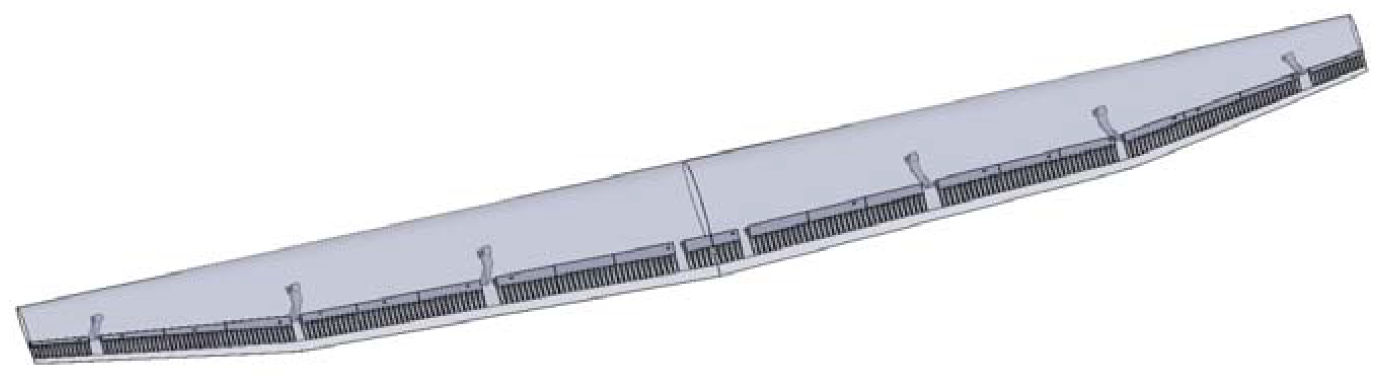
As an open shell structure, the wing skin had very limited load-bearing capability since the load was likely to be carried only by the lower skin in a normal upward load case situation, also due to low buckling loads of the skin alone. The design concept relied on the restriction of the relative upper and lower skin TEs displacements in the chordwise direction to force the upper and lower skins to carry the bending loads simultaneously. This restriction was enforced by the addition of sliding “comb-like” parts that were bonded near and along the TEs of the upper and lower skins and are depicted in Figure 5.
As for torsional stiffness and controlled twist and camber deformation, the concept relied on the actuation system capability to carry the load and deform the wing sections using a mix of linear and rotational servos distributed along the wingspan.
A total of six rotational servos and two linear servos were used. In order to increase the actuation speed while maneuvering, the rotational servos were used everywhere other than at the root. The implications of this choice were a constant power consumption required to maintain a prescribed configuration during flight that increases for configurations with increased camber. It is still to be investigated if linear actuators can satisfactorily fit and actuate the wing fast enough to allow acceptable roll rates and load alleviation strategies.
The linear servos were used at the root. They did not contribute to the roll maneuverability and serve as actuation for configuration setting only, which was deemed to change shape somewhat slower without jeopardizing the configuration adaptation to different flight segments. This choice allowed higher actuation loads in the wing region where they were required to maintain the desired shape, without energy expenditure while the configuration was maintained. It is still to be investigated if the lower actuation speed is compatible with a load alleviation strategy that increases camber at the root while decreasing camber and twist towards the tip of the wing.
Structural members as stiffeners could also be valid options in the design since they act primarily in bending without a significant increase in actuation forces, but the current concept was intended to explore load alleviation capabilities as means to maintain the wing structure as mass competitive as possible, by limiting the root bending moment (RBM) during maneuvering or gust loads.
2.4. Actuation Principles
For a given wing configuration, only three parameters define it: root actuation, kink actuation, and tip actuation setpoints. This means that the inboard rotational servos and the leading-edge linear servo could be actuated independently for a configuration setting: the inboard rotational servos setpoint was interpolated using the root and kink actuation setpoints while the linear servos set points were proportionally related.
During a roll maneuver, the kink and tip servos set points were changed in order to increase camber and twist on one side of the wing while decreasing those parameters on the other side, achieving a lift differential between both sides and a corresponding rolling moment. The linear servos at the root maintained their positions while the inboard rotational servos set point were changed to the new interpolated setpoint if the kink setpoint was changed.
For load alleviation, there was a reduction in the kink and tip actuation set points—with a corresponding camber and twist decrease—and root actuation setpoint increased—with corresponding camber increase and further twist decrease along the span—which should bring the lift distribution towards the center of the wing and reduce its RBM.
2.5. Experimental Procedure
The experimental determination of the deformed shapes assumes that the position of a point in the wing surface could be determined based on video footage from two different cameras rotated around a fixed axis parallel to the wing’s straight LE. With reference to Figure 6, the position of a point P on the wing surface can be described either relative to the reference frame xyz or reference frame x′y′z′. A simple rotation of an angle θ around the x-axis transforms the coordinates of P from one frame to the other.
Equation (1) relates the two sets of coordinates and describes the formula to obtain the coordinate z of a point knowing the (y, y′) pair. Therefore, from two projections in different planes, one can obtain the full set of coordinates of a point P.
While for camera view #1, parallel to the wing planform, the resulting footage corresponds to a projection on the xy plane, the same did not apply for camera view #2. Figure 6 shows the distortion of the image when the view plane is not parallel to the wing planform caused by the depth variation for the points on the surface. Knowing the wing dimensions, a scaling factor function of y′ could be generated to correct the distortion and obtain the desired projection in the plane x′y′. One could then proceed with the z coordinate calculation for a spatial description of the wing surface using Equation (1). The same procedure could be applied to the lower wing surface.
3. Ground Testing
The purpose of the ground tests was to quantify the changes in shape, the actuation power, and energy requirements along with the combined wing mass and actuation system mass.
Using the quantified camber and twist differences between different actuation configurations, estimates of variations in lift distribution, rolling moment, and RBM could be calculated, resorting to the lifting line theory (LLT) coupled with viscous airfoil data estimates used in [26].
3.1. Comparison of Deformed Shapes
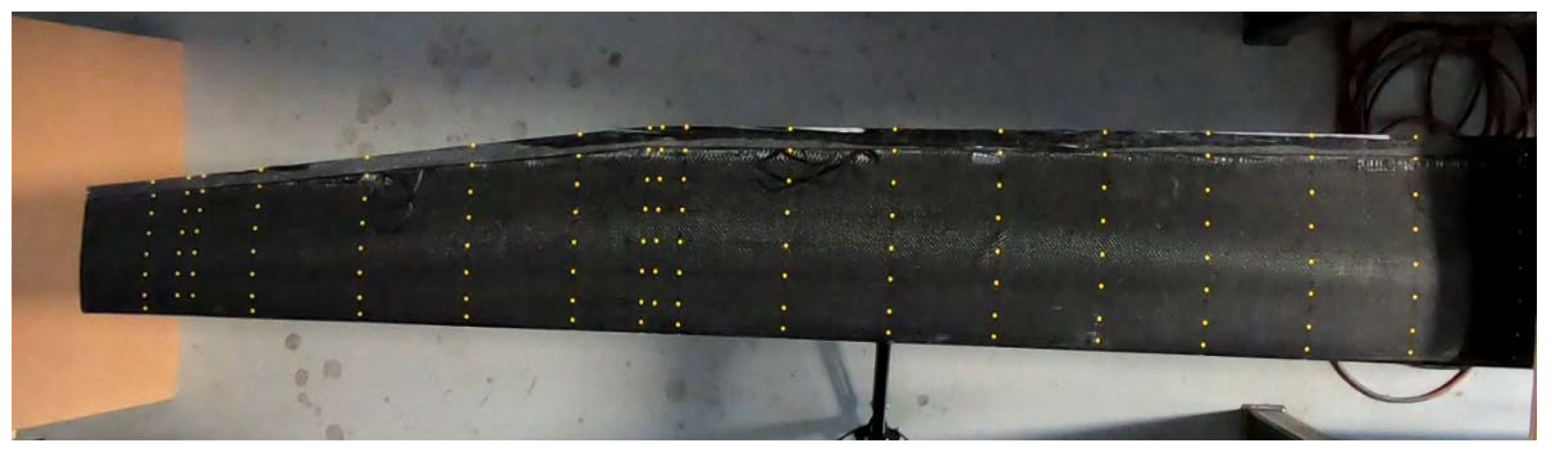
The deformed shapes were experimentally quantified using video of the wing under actuation from four different locations around the same axis: Two positions to determine the shape of the lower surface and two positions to determine the shape of the upper surface. A set of wing sections along the span were discretized using yellow sticker dots placed chordwise in each section, as shown in Figure 7.
Tracking software [27] allowed tracking the position of the yellow sticker dots depicted in Figure 7 in a 2D plane parallel to the camera lenses while the wing is actuated. If a second set of footage was taken by rotating the camera around an axis parallel to the wing’s unswept leading edge, the third coordinate could be calculated from the two sets of 2D positions tracked with the two different camera positions, given that the rotation angle and axis were known as explained earlier. Scaling factors needed to be applied to account for the differences in depth from the sticker dots to the camera when the camera is not parallel to the wing surface.
Figure 8 depicts the experimental apparatus.
Given the position in a 3D reference frame of the points of different airfoil sections along the chord and span were obtained, twist and camber for each of the sections could be obtained.
The wing was actuated and its shapes were measured for six main actuation configurations. For each main configuration, other configurations were measured corresponding to the full actuation configurations during roll maneuvers, acting as described earlier. If the main configuration was at an extreme of the actuation range, i.e., uncambered or fully cambered in all stations, only the other available full actuation configuration for rolling was measured. If the main configuration was between extremes, two other configurations were measured corresponding to uncambered and fully cambered roll configurations. Table 1 describes the actuation of each servo for the measured configurations in percentage of throw.
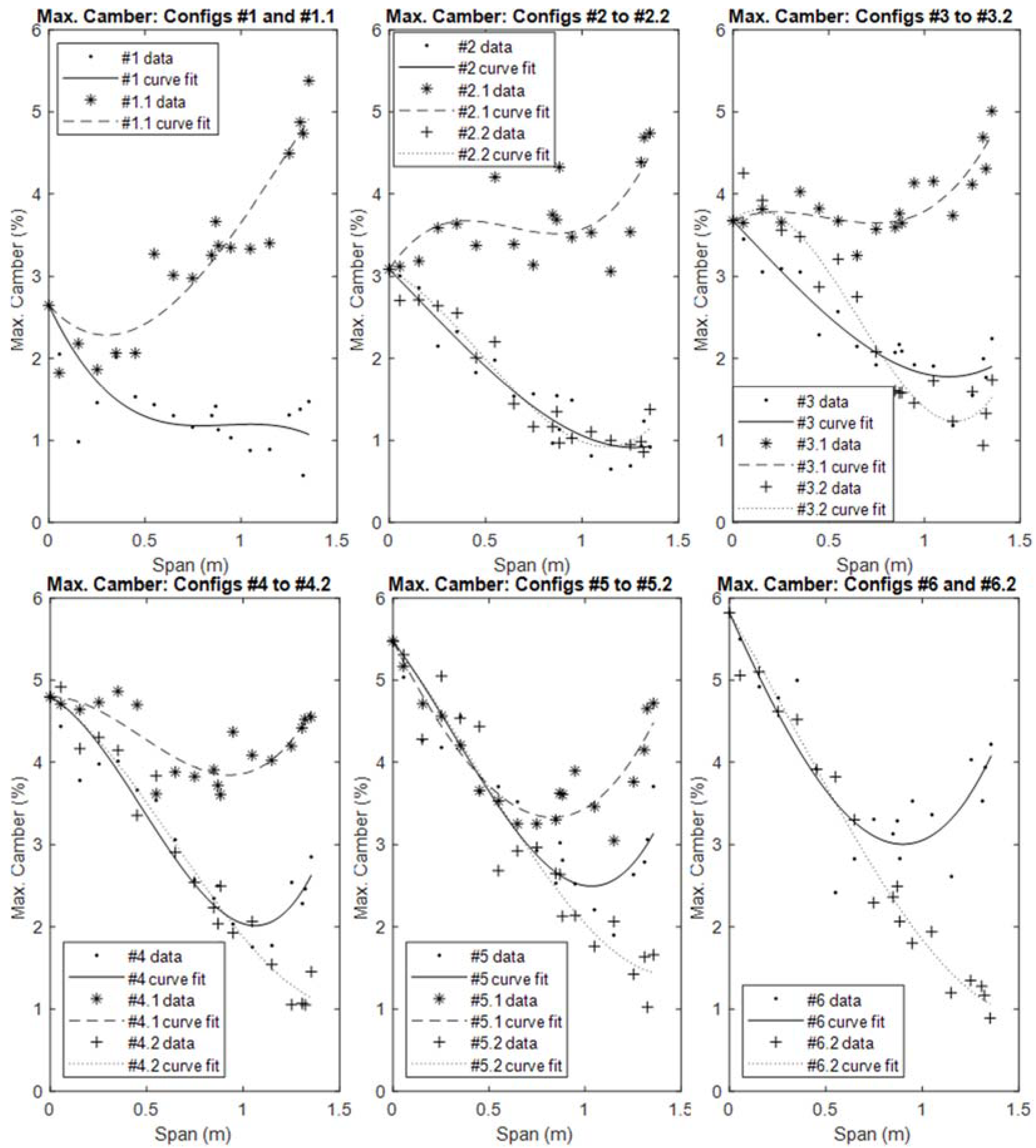
Figure 9 and Figure 10 depict the measured twist and camber distributions along the half span of the wing for the different configurations in Table 1, respectively. The expected trends were verified, with the magnitude of the negative tip twist being increased as the root camber increases and the tip twist variation being positive as the camber increased at or towards the tip. Nevertheless, the discretization and accuracy of the measurements did not allow the verification of a continuous twist and camber variation along the span, which were therefore approximated by least-squares fit of cubic polynomial curves. These fitting curves were subsequently used for the estimation of roll rates, RBMs, and L/D values.
3.2. Estimation of Root Bending Moment (RBM) and Roll Rates
From the twist and camber distributions obtained and using the expected airfoil cambered shapes data as well as the 2D CL curves for those airfoils from [18], it was possible to correlate the local camber with a local zero-lift angle of attack and local lift slope, therefore, making it possible to analyze the current wing shape using the LLT. Figure 11 depicts an example of the half-spanwise lift distributions for a total lift of 39.22 N, corresponding to a 4 Kg maximum take-off mass (MTOM), and a speed of 12 m/s of the main configurations together with the lift distributions of the maneuvering configurations at the same angle of attack (AOA) as the main configuration.
It was noticed that the main configurations (solid lines) varied from closer to elliptical lift distribution in configuration 1 to increasingly steeper triangular distributions as the overall wing camber was increased from configurations #2 to #6. This was a consequence of the above-mentioned intense negative twist variation induced by the camber increase at the inboard part of the span, which more than overcame the combined effect of camber and twist angle increase caused by actuation at the outboard region of the wing.
The resultant RBM for the different main configurations was therefore significantly affected by the lift distribution, as could be observed from the data in Table 2 below:
Therefore, the RBM could be significantly reduced if one was able to detect/predict the load increase and change the configuration sufficiently fast. This corresponds to an active load alleviation strategy that could potentially be used to either reduce the structural requirements on the wing structural design, therefore, reducing structural weight, or increase the magnitude of the total load-bearing capability of the structure, therefore, increasing the maximum operational load factor and maneuverability.
A simplistic quantification of the potential maximum operational load increase stems directly from the RBM variation from configuration #1 to #5, which suggests that this load could increase from 16% up to 49%, depending on the current flight speed.
Regarding the roll authority of this morphing concept prototype, the rolling moment was obtained by assuming different lift distributions on the right- and left-wing sides (i.e., configurations *.1 and *.2 for main configurations #2 to #5, configurations #1 and #1.1 for main configuration #1 and configurations #6 and #6.2 for main configuration #6) and calculating the difference between RBM for each side.
Table 3 shows the obtained values for the maximum achievable rolling moment coefficient (Cl) for each main configuration for different flight speeds:
The calculated rolling moment coefficients magnitudes were very modest when compared to what could be obtained with moderate aileron deflections of 15 deg in a Cessna 152 aircraft (0.047), which indicated potential difficulties in attaining high levels of roll authority with this concept.
Augmentation of roll authority might be achievable by improving the actuation system to provide the configuration with more camber in the first two-thirds of the wing, which would provide both a lift increase in that region and in the last third of the wingspan by means of reducing the negative twist in the *.1 configurations.
3.3. Estimation of L/D
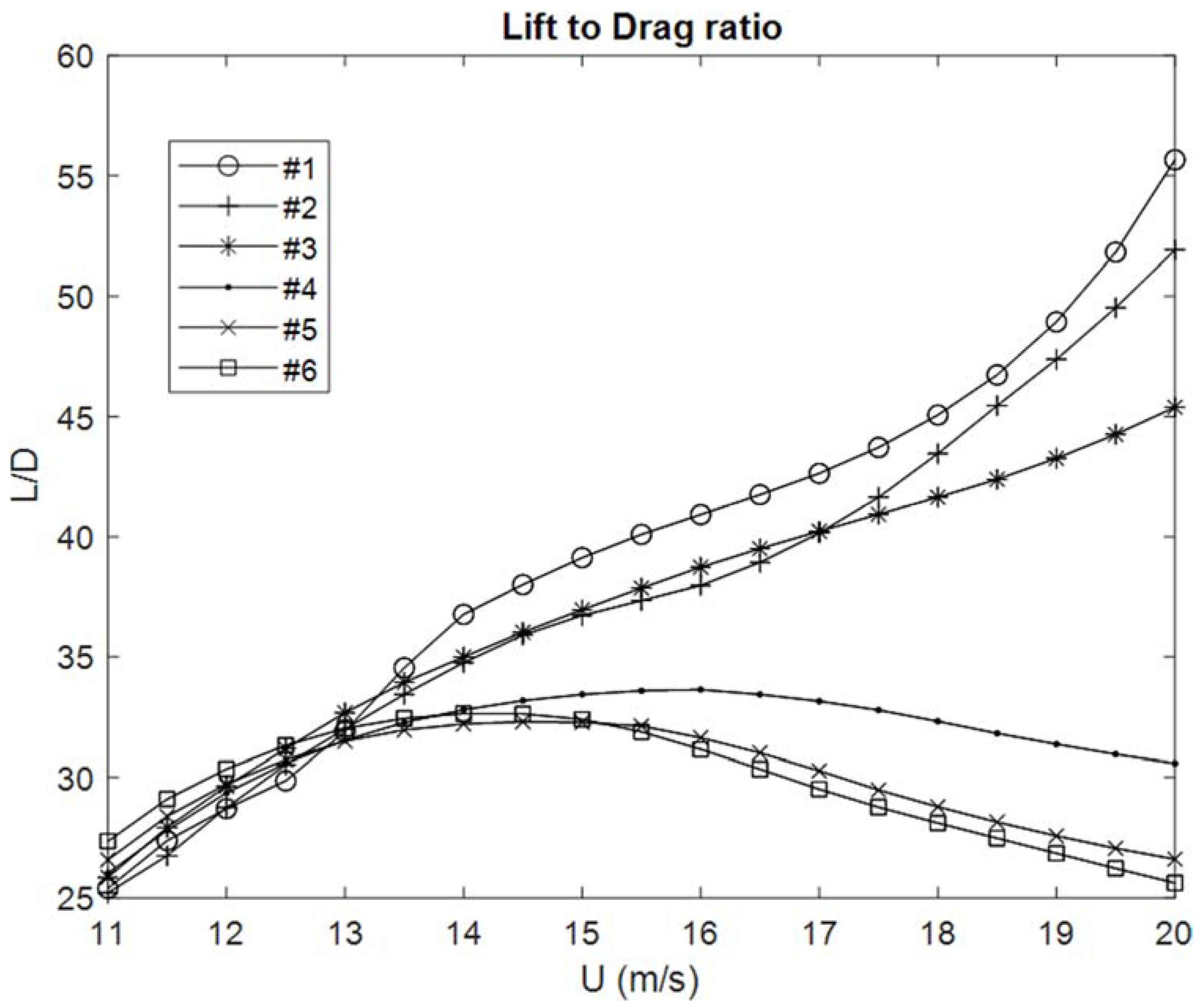
The LLT analysis coupled with the 2D airfoil data also allowed estimation of the L/D of each configuration as a function of speed. The L/D vs. speed is depicted in Figure 12 below for each main configuration assuming leveled flight and an MTOM of 4 kg.
As could be expected, the lowest camber configuration #1 showed the best aerodynamic efficiency for moderate to higher speeds. More cambered configurations showed improvements relatively to configuration #1 only when the AOA became high at lower speeds. They also reduced the stall speed relative to configuration 1.
Once again, the intense negative twist variation with a root camber increase penalized the efficiency of cambered configurations at moderately low speeds when compared to configuration #1. The expectation of a more gradual morphing strategy for maximum efficiency within the flight speed envelope was not fulfilled with the current prototype. Nevertheless, it could be noticed that there are more than two configurations showing the best performance within this flight speed envelope, with configuration #6 being the most efficient at low speeds, configuration #5 being the most efficient at 13 m/s, and configuration #1 being the most efficient at speeds of 13.5 m/s and above.
3.4. Wing Mass and Actuation Energy Estimates
Table 4 shows the wing’s mass breakdown. One can notice that compared to the assumed MTOM the wing mass is about 44% and thus excessively high. The actuation and support components comprised 9.4% of the MTOM while the wing skin and internals comprised 34.6%.
One could argue that either the wing may allow a high operational load factor or that the MTOM could be increased in order to justify this wing system mass. Although the load tests were performed as shown in Figure 13, the maximum load applied to the wing with an approximately elliptical distribution was equivalent to a load factor of 2.2 g without signs of structural failure but with visible airfoil shape deformation in the second quarter of the wing.
The wing was also actuated with and without this load and the power required for the same actuation requests was recorded in both cases, as shown in Table 5.
As expected, actuation power increases with the configuration camber. The same trend was seen with maneuvering power. As for the effect of load on actuation power, it shows an increase that varied with the configuration up 129%.
The power consumption naturally implied a mass penalty as the actuation energy must be provided by some energy source. As is frequent with morphing solutions, the penalties might outweigh the benefits if the mission does not favor the potential of the concept. For example, maintaining cambered configurations for long periods of time may jeopardize potential structural mass reduction benefits from the load alleviation capability.
Both depreciative factors (excess mass and actuation energy consumption) could be mitigated with a more careful design. It seems reasonable to expect wing skin mass reductions of about 33% with replacement of the paper and resin material between fiber plies with foam as previously mentioned. Internal parts supporting servos and the “comb-like” parts could also be improved. As for the actuation energy, extending the use of linear actuators as much as possible would reduce the energy requirements to maintain the configuration shape, making the energetic expenditures dependent only on the amount of configuration transitions and maneuvers required in a flight mission.
4. Flight Tests
Even considering the estimated low roll authority, flight testing was attempted with the current wing prototype. For that purpose, a simple tail and boom fuselage was built to carry the necessary avionics and battery for gliding flight. Bungee launching was used to get the aircraft with sufficient speed to climb and glide.
During this short initial flight, the wing was able to turn left, right and maintain flight with wings leveled as can be seen in Figure 14.
The pilot in command described the roll control authority as not abundant but sufficient to ensure roll control at least under the calm wind flight conditions at which the test was made.
5. Discussion
An experimental validation of a coupled twist and camber morphing wing concept was performed and performance was evaluated based on ground and flight tests. The concept provides roll control, improved flight efficiency, and load alleviation potential.
The ground tests validated the target shapes of the wing for different actuation configurations. These shapes were later used to estimate roll control authority, RBM variation, and L/D for the various configurations tested. Preliminary results show that roll authority is low when compared to a general aviation aircraft, RBM reduction potential is high and the morphing concept presents benefits when adapting the configurations for different flight conditions.
Other important challenges to overcome in order to make the concept more attractive include mass reduction and actuation energy. The current prototype mass was excessive and the continuous energy expenditure required to maintain the configuration shape needs to be avoided or at least mitigated. Nevertheless, a significant margin for improvement exists in these two areas, along with improving roll authority.
Flight tests did not include the quantification of either the actual aerodynamic efficiency differences between configurations or the verification of the load alleviation capability in flight. However, it was possible to assess qualitatively the roll authority provided by the wing when actuated in a morphed configuration with no root actuation, which was deemed to be adequate. The preliminary flight test campaign suggested further prototype developments and quantitative testing were needed.
6. Patents
A patent application is undergoing based on the work reported in this article.
Author Contributions
Conceptualization, J.L.d.V.; methodology, J.L.d.V.; formal analysis, J.L.d.V.; investigation, J.L.d.V., J.R.; resources, A.S.; data curation, J.L.d.V.; writing—original draft preparation, J.L.d.V.; writing—review and editing, J.R. and A.S.; supervision, A.S.; project administration, A.S. All authors have read and agreed to the published version of the manuscript.
Funding
A.S. acknowledges the NSERC Canada Research Chair funding program and the Fundação para a Ciência e a Tecnologia (FCT), through IDMEC, under LAETA, project UIDB/50022/2020.
Institutional Review Board Statement
Not applicable.
Informed Consent Statement
Not applicable.
Data Availability Statement
Acknowledgments
The authors are grateful to the personnel at the Center for Aerospace Research at the University of Victoria for the support provided during the experimental tests.
Conflicts of Interest
The authors declare no conflict of interest.
References
- Li, D.; Zhao, S.; Da Ronch, A.; Xiang, J.; Drofelnik, J.; Li, Y.; Zhang, L.; Wu, Y.; Kintscher, M.; Monner, H.P.; et al. A review of modelling and analysis of morphing wings. Prog. Aerosp. Sci. 2018, 100, 46–62. [Google Scholar] [CrossRef] [Green Version]
- Li, W.; Jin, D. Flutter suppression and stability analysis for a variable-span wing via morphing technology. J. Sound Vib. 2018, 412, 410–423. [Google Scholar] [CrossRef]
- Zhang, J.; Shaw, A.D.; Wang, C.; Gu, H.; Amoozgar, M.; Friswell, M.I.; Woods, B.K. Aeroelastic model and analysis of an active camber morphing wing. Aerosp. Sci. Technol. 2021, 111, 106534. [Google Scholar] [CrossRef]
- Burdette, D.A.; Martins, J. Design of a transonic wing with an adaptive morphing trailing edge via aerostructural optimization. Aerosp. Sci. Technol. 2018, 81, 192–203. [Google Scholar] [CrossRef]
- Zhang, Z.; De Gaspari, A.; Ricci, S.; Song, C.; Yang, C. Gradient-Based Aerodynamic Optimization of an Airfoil with Morphing Leading and Trailing Edges. Appl. Sci. 2021, 11, 1929. [Google Scholar] [CrossRef]
- Zhang, Y.; Ge, W.; Zhang, Z.; Mo, X.; Zhang, Y. Design of compliant mechanism-based variable camber morphing wing with nonlinear large deformation. Int. J. Adv. Robot. Syst. 2019, 16, 1729881419886740. [Google Scholar] [CrossRef]
- De Gaspari, A.; Moens, F. Aerodynamic Shape Design and Validation of an Advanced High-Lift Device for a Regional Aircraft with Morphing Droop Nose. Int. J. Aerosp. Eng. 2019, 2019, 7982168. [Google Scholar] [CrossRef] [Green Version]
- De Gaspari, A.; Cavalieri, V.; Ricci, S. Advanced Design of a Full-Scale Active Morphing Droop Nose. Int. J. Aerosp. Eng. 2020, 2020, 1086518. [Google Scholar] [CrossRef]
- Künnecke, S.C.; Vasista, S.; Riemenschneider, J.; Keimer, R.; Kintscher, M. A review of adaptive shock control systems. Appl. Sci. 2021, 11, 817. [Google Scholar] [CrossRef]
- Di Luca, M.; Mintchev, S.; Heitz, G.; Noca, F.; Floreano, D. Bioinspired morphing wings for extended flight envelope and roll control of small drones. Interface Focus 2017, 7, 20160092. [Google Scholar] [CrossRef] [PubMed]
- Jenett, B.E.; Calisch, S.E.; Cellucci, D.; Cramer, N.; Gershenfeld, A.N.; Swei, S.; Cheung, K.C. Digital Morphing Wing: Active Wing Shaping Concept Using Composite Lattice-Based Cellular Structures. Soft Robot. 2017, 4, 33–48. [Google Scholar] [CrossRef] [PubMed] [Green Version]
- Ermakova, A.; Dayyani, I. Shape optimisation of composite corrugated morphing skins. Compos. Part B Eng. 2017, 115, 87–101. [Google Scholar] [CrossRef] [Green Version]
- Schlup, A.; Bishay, P.; McLennan, T.; Barajas, C.; Talebian, B.; Thatcher, G.; Flores, R.; Perez-Norwood, J.; Torres, C.; Kibret, K.; et al. MataMorph 2: A new experimental UAV with twist-morphing wings and camber-morphing tail stabilizers. In Proceedings of the AIAA SciTech 2021 Forum, Nashville, TN, USA, 11–15 January 2021. [Google Scholar] [CrossRef]
- Kaygan, E.; Ulusoy, C. Effectiveness of Twist Morphing Wing on Aerodynamic Performance and Control of an Aircraft. J. Aviat. 2018, 2, 77–86. [Google Scholar] [CrossRef]
- Nugroho, B.; Brett, J.; Bleckly, B.; Chin, R. Numerical study of geometric morphing wings of the 1303 UCAV. Aeronaut. J. 2021, 125, 1192–1208. [Google Scholar] [CrossRef]
- De Breuker, R.; Werter, N. On the Importance of Morphing Deformation Scheduling for Actuation Force and Energy. Aerospace 2016, 3, 41. [Google Scholar] [CrossRef] [Green Version]
- Novel Air Vehicles Configurations: From Fluttering Wings to Morphing Flight (NOVEMOR), Grant Agreement ID: 285385, Programme FP7-TRANSPORT—Specific Programme “Cooperation”: Transport (Including Aeronautics). Available online: https://cordis.europa.eu/project/id/285395 (accessed on 1 October 2021).
- Smart Intelligent Aircraft Structures (SARISTU), Grant Agreement ID: 284562, Programme FP7-TRANSPORT—Specific Programme “Cooperation”: Transport (Including Aeronautics). Available online: https://cordis.europa.eu/project/rcn/100047/factsheet/en (accessed on 1 October 2021).
- Verrastro, M.; Dimino, I. Chapter 21—Morphing Devices: Safety, Reliability, and Certification Prospects. In Morphing Wing Technologies, 1st ed.; Concilio, A., Dimino, I., Lecce, L., Pecora, R., Eds.; Elsevier Ltd.: New York, NY, USA, 2018; pp. 647–682. [Google Scholar]
- Arena, M.; Concilio, A.; Pecora, R. Aero-servo-elastic design of a morphing wing trailing edge system for enhanced cruise performance. Aerosp. Sci. Technol. 2019, 86, 215–235. [Google Scholar] [CrossRef]
- Clean Sky, Grant Agreement ID: 284562, Programme FP7-TRANSPORT—Specific Programme “Cooperation”: Transport (Including Aeronautics). Available online: https://www.cleansky.eu/ (accessed on 1 October 2021).
- Ameduri, S.; Concilio, A.; Dimino, I.; Pecora, R.; Ricci, S. AIRGREEN2—Clean Sky 2 programme: Adaptive wing technology maturation, challenges and perspectives. In Proceedings of the ASME Conference on Smart Materials, Adaptive Structures and Intelligent Systems, San Antonio, TX, USA, 10–12 September 2018; ASME: New York, NY, USA, 2018. Paper No. SMASIS2018-8235. [Google Scholar]
- Dimino, I.; Andreutti, G.; Moens, F.; Fonte, F.; Pecora, R.A. Integrated Design of a Morphing Winglet for Active Load Control and Alleviation of Turboprop Regional Aircraft. Appl. Sci. 2021, 11, 2439. [Google Scholar] [CrossRef]
- Ameduri, S.; Dimino, I.; Mercurio, U.; Pellone, L. Specific Modeling Issues on an Adaptive Winglet Skeleton. Appl. Sci. 2021, 11, 3565. [Google Scholar] [CrossRef]
- Vale, J.; Leite, A.; Lau, F.; Suleman, A. Aero-structural optimization and performance evaluation of a morphing wing with variable span and camber. J. Intell. Mater. Syst. Struct. 2011, 22, 1057–1073. [Google Scholar] [CrossRef]
- Vale, J.; Afonso, F.; Oliveira, É.; Lau, F.; Suleman, A. An optimization study on load alleviation techniques in gliders using morphing camber. Struct Multidisc Optim. 2017, 56, 435–453. [Google Scholar] [CrossRef]
- Tracker—Video Analysis and Modelling Tool. Available online: https://physlets.org/tracker/ (accessed on 30 August 2021).
Figure 1.
Optimization results (reproduced from [25]). (a) Thickness distribution; (b) aerodynamic loading; (c) unactuated unloaded; (d) unactuated loaded; (e) actuated unloaded; (f) actuated loaded.
Figure 1.
Optimization results (reproduced from [25]). (a) Thickness distribution; (b) aerodynamic loading; (c) unactuated unloaded; (d) unactuated loaded; (e) actuated unloaded; (f) actuated loaded.

Figure 2.
Data flow for calculations during the actuation distribution optimization procedure. Data generation for objective function and constraints calculation (up); surrogate twist and FEM twist results comparison and surrogate model update procedure (down) (reproduced from [26]).
Figure 2.
Data flow for calculations during the actuation distribution optimization procedure. Data generation for objective function and constraints calculation (up); surrogate twist and FEM twist results comparison and surrogate model update procedure (down) (reproduced from [26]).

Figure 3.
Planform detail of the FEM (up); actuation stress intensity in design conditions (down left) and detail of the tip airfoil twist compared to the unactuated position (down right) (reproduced from [26]).
Figure 3.
Planform detail of the FEM (up); actuation stress intensity in design conditions (down left) and detail of the tip airfoil twist compared to the unactuated position (down right) (reproduced from [26]).

Figure 4.
Tip airfoil under different spanwise actuation distributions.

Figure 5.
CAD representation of the “comb-like” parts and inner actuation system supports.

Figure 6.
Camera positions, views, and reference frames for determination of coordinates of wing surface points.
Figure 6.
Camera positions, views, and reference frames for determination of coordinates of wing surface points.

Figure 7.
Wing sections discretized along the wingspan using sticker dots.

Figure 8.
Test apparatus, lower surface up.

Figure 9.
Spanwise twist for the selected configurations.

Figure 10.
Spanwise camber for the selected configurations.

Figure 11.
Spanwise lift distributions of the selected configurations.

Figure 12.
Estimated L/D variation with speed for the main configurations.

Figure 13.
Morphing wing load test.

Figure 14.
Morphing wing gliding flight.


Table 1.
Actuation levels for the different configurations.
| Config. # | Root Act. (%) | Kink (%) | Tip (%) |
|---|---|---|---|
| 1 | 0 | 0 | 0 |
| 1.1 | 0 | 100 | 100 |
| 2 | 17 | 17 | 17 |
| 2.1 | 17 | 100 | 100 |
| 2.2 | 17 | 0 | 0 |
| 3 | 33 | 33 | 33 |
| 3.1 | 33 | 100 | 100 |
| 3.2 | 33 | 0 | 0 |
| 4 | 50 | 50 | 50 |
| 4.1 | 50 | 100 | 100 |
| 4.2 | 50 | 0 | 0 |
| 5 | 67 | 67 | 67 |
| 5.1 | 67 | 100 | 100 |
| 5.2 | 67 | 0 | 0 |
| 6 | 100 | 100 | 100 |
| 6.2 | 100 | 0 | 0 |
Table 2.
RBM differences to configuration #1 at different speeds.
| U (m/s) | RBM #1 (N·m) | ΔRBM #2 (%) | ΔRBM #3 (%) | ΔRBM #4 (%) | ΔRBM #5 (%) | ΔRBM #6 (%) |
|---|---|---|---|---|---|---|
| 12 | 12.47 | −5.8 | −8.6 | −13.2 | −15.6 | −12.8 |
| 16 | 12.04 | −12.5 | −18.2 | −26.5 | −30.6 | −25.2 |
| 20 | 11.22 | −20.3 | −28.6 | −43.0 | −48.6 | −39.1 |
Table 3.
Estimated maximum rolling moment coefficient (Cl) for each main configuration.
| Cl | #1 | #2 | #3 | #4 | #5 | #6 |
|---|---|---|---|---|---|---|
| U = 12 m/s | 0.0062 | 0.0074 | 0.0148 | 0.0134 | 0.0119 | 0.0119 |
| U = 16 m/s | 0.0059 | 0.0085 | 0.0163 | 0.0144 | 0.0126 | 0.0129 |
| U = 20 m/s | 0.0034 | 0.0093 | 0.0168 | 0.0152 | 0.0132 | 0.0137 |
Table 4.
Morphing wing mass breakdown.
| Component | Mass (g) | % of MTOW |
|---|---|---|
| Wing Skin | 1094 | 27.4 |
| Internals | 286 | 7.2 |
| Rotational servos | 186 | 4.7 |
| Linear servos | 116 | 2.9 |
| LE support | 38 | 1.0 |
| TE support | 20 | 0.5 |
| Total | 1740 | 43.5 |
Table 5.
Actuation power for different configurations.
| Power (W) | #1 | #1.* | #2 | #2.* | #3 | #3.* | #4 | #4.* | #5 | #5.* | #6 | #6.* |
|---|---|---|---|---|---|---|---|---|---|---|---|---|
| Unloaded | 0.0 | 16.2 | 0.7 | 15.9 | 4.4 | 16.7 | 12.4 | 14.4 | 22.4 | 22.6 | 21.3 | 26.3 |
| Loaded | 0.0 | 20.1 | 0.8 | 22.0 | 7.0 | 21.6 | 28.4 | 22.9 | 26.4 | 32.6 | 27.0 | 37.9 |
| Δ (%) | 0.0 | 24.1 | 14.3 | 38.4 | 59.1 | 29.3 | 129.0 | 59.0 | 17.9 | 44.2 | 26.8 | 44.1 |
Publisher’s Note: MDPI stays neutral with regard to jurisdictional claims in published maps and institutional affiliations. |
© 2021 by the authors. Licensee MDPI, Basel, Switzerland. This article is an open access article distributed under the terms and conditions of the Creative Commons Attribution (CC BY) license (https://creativecommons.org/licenses/by/4.0/).
Share and Cite
MDPI and ACS Style
Lobo do Vale, J.; Raffaelli, J.; Suleman, A. Experimental Validation and Evaluation of a Coupled Twist-Camber Morphing Wing Concept. Appl. Sci. 2021, 11, 10631. https://0-doi-org.brum.beds.ac.uk/10.3390/app112210631
AMA Style
Lobo do Vale J, Raffaelli J, Suleman A. Experimental Validation and Evaluation of a Coupled Twist-Camber Morphing Wing Concept. Applied Sciences. 2021; 11(22):10631. https://0-doi-org.brum.beds.ac.uk/10.3390/app112210631
Chicago/Turabian StyleLobo do Vale, José, John Raffaelli, and Afzal Suleman. 2021. "Experimental Validation and Evaluation of a Coupled Twist-Camber Morphing Wing Concept" Applied Sciences 11, no. 22: 10631. https://0-doi-org.brum.beds.ac.uk/10.3390/app112210631
Note that from the first issue of 2016, this journal uses article numbers instead of page numbers. See further details here.