
Theoretical Investigation on the Impact of Two HDR Dampers on First Modal Damping Ratio of Stay Cable


1
Faculty of Road and Bridge Engineering, The University of Danang–University of Science and Technology, Danang 550000, Vietnam
2
Department of Civil Engineering, East West University, A/2, Jahurul Islam Avenue, Jahurul Islam City, Aftabnagar, Dhaka 1212, Bangladesh
*
Author to whom correspondence should be addressed.
Appl. Sci. 2021, 11(22), 10985; https://0-doi-org.brum.beds.ac.uk/10.3390/app112210985
Submission received: 5 November 2021
/
Revised: 17 November 2021
/
Accepted: 17 November 2021
/
Published: 19 November 2021
(This article belongs to the Special Issue Vibration Control and Applications)
Abstract
:Stay cables are one of the vital components of a cable-stayed bridge. Due to their flexible nature, stay cables are vulnerable to external excitation and often vibrate with large amplitude under wind action which leads to the fatigue failure of the cables. To suppress such kind of large amplitude vibration by improving the damping ratio of the cable various dampers such as magnetorheological damper, friction damper; oil damper; or high damping rubber (HDR) damper are utilized and gained popularity over time. This paper focuses on improving the damping ratio of stay cables using a combination of two HDR dampers. First, the theoretical model is formulated considering cable bending stiffness to evaluate the damping effect of cable-HDR dampers system. Then, the impact of various design parameters of HDR dampers on cable damping considering the cable stiffness is performed. The comparative analysis of results shows that the considered parameters such as loss factor, spring factor, and installation location of dampers have much effect on the stay cables damping ratio. Finally, the optimal parameters of the two HDR dampers are proposed for damper design.
1. Introduction
Stay cables have low mass, low frequencies, and low damping ratio, so they are vulnerable to external excitation. The vibration of stay cable under ambient excitation (such as wind or earthquake loading) and live load can cause fatigue in cable attachment, which might reduce the bridge safety. There are mainly two methods to control cable vibration. The first method is to modify the cable surface to improve its aerodynamic performance [1,2,3] and the other one is to install the energy dissipating devices such as magnetorheological damper, friction damper; oil damper; or HDR damper [4,5,6,7,8,9,10,11,12,13,14,15,16,17,18,19,20,21,22,23,24,25,26,27]. The installation of an external damper can increase the cable damping ratio. Consequently, its vibration was mitigated.
Studies into the cable vibration with an external damper including an HRD damper have been investigated by many researchers [4,5,6,7,8,9,10,11,12,13,14,15,16,17,18,19,20,21,22,23,24,25,26,27]. Single HDR damper device has widely been applied for stayed cables with short lengths as it can efficiently dissipated the vibration energy of the cable. Nakamura et.al. [6] optimized the parameters of single HDR damper for obtaining the maximum damping of stay cable. In addition, Fujino Y., and Nam H. [7] proposed the formulas for calculating the cable damping ratios of stay cable with a single HDR-damper. Cu et al., further investigated on stay cable with HDR damper [11]. They found that the damping ratio has strong dependency on loss factor and damper location. However, their study did not consider the bending stiffness of taut cable for calculating the cable damping. Recently, Le et al. (2020) also proposed an approximated formula for estimating the damping ratio of a stay cable with single HDR-damper considering the uncertainties of boundaries conditions [12]. They concluded that the efficiency of the damper can be increased by adding more rotational restrain stiffness. According to previous studies [4,9,10,11], the maximum modal damping of stay cable is directly proportional to the distance of the damper from its end. The effect of single HDR damper and other damper types on stay cable damping has attracted many further studies [4,6,8,9,11,12,13,14,15,16,17,18]. However, due to the bridge aesthetic, the damper is often installed near the cable end within a few percentages of cable length that lessens the efficiency of the damper. Therefore, it is difficult to obtain an expected damping level using a single damper for very long-stay cables [4]. In this regard, the use of two dampers at different locations can provide a possible countermeasure to suppress the cable vibration by increasing the total damping [10]. Caracoglia et.al. [19] investigated the impact of two viscous dampers on taut cable damping. They figured out that the dampers located at opposite ends of taut cable can enhance the damping as compared to the case with dampers installed on one side near the bridge deck. Nam H. and Fujino Y. [10] also confirmed that the total damping ratio of cable with two dampers is equal to the summation of two single damper effects. Xu and Yu [20] presented a numerical example of combining two oil dampers to increase the stay cable damping ratio. This study showed that damper stiffness, damper installation location, and oil-damper direction influent its effectiveness. Furthermore, according to Tabatabai and Mehrabi [21], bending stiffness affects noticeably the damping ratio of stay cable. These authors have developed a numerical framework to calculate vibration frequencies and damping ratios of sagging cables with non-negligible bending stiffness equipped with a viscous damper. Vo and Nguyen proposed the theoretical model for evaluating damping of stay cable with two friction dampers to reduce cable galloping considering cable bending stiffness [22]. Fangdian Di et al., investigated the effect of HDR and viscous dampers to increase cable damping by theoretical analysis and field experiments [23]. In addition, Haijun Z. et al., reported the field measurement for stay cable with different type of dampers. They figured out that the damping of field measurement is lower than the theoretical value [24]. Other studies on viscous dampers combined with internal devices to enhance cable damping were also proposed [25,26,27]. As discussed above, most of the previous studies mainly focused on the effects of single damper, two viscous dampers or viscous damper combined with another type. The model for estimating the cable damping ratio of two HDR dampers considering the cable bending stiffness has been not studied yet and their effect is also not fully understood.
In this study, the performance of stay cable with two HDR dampers is investigated to obtain higher damping ratio. Particularly, the theoretical model is proposed to evaluate damping effect of the cable with two HDR dampers considering its bending stiffness. The impact of loss factor, spring factor, dampers installation positions, and bending stiffness (EJ) of stay cable on the first modal damping ratio is also elucidated. Finally, an optimization study for two HDR dampers is carried out and discussed in detail.
2. Governing Equation of Stay Cable with Two HDR Dampers
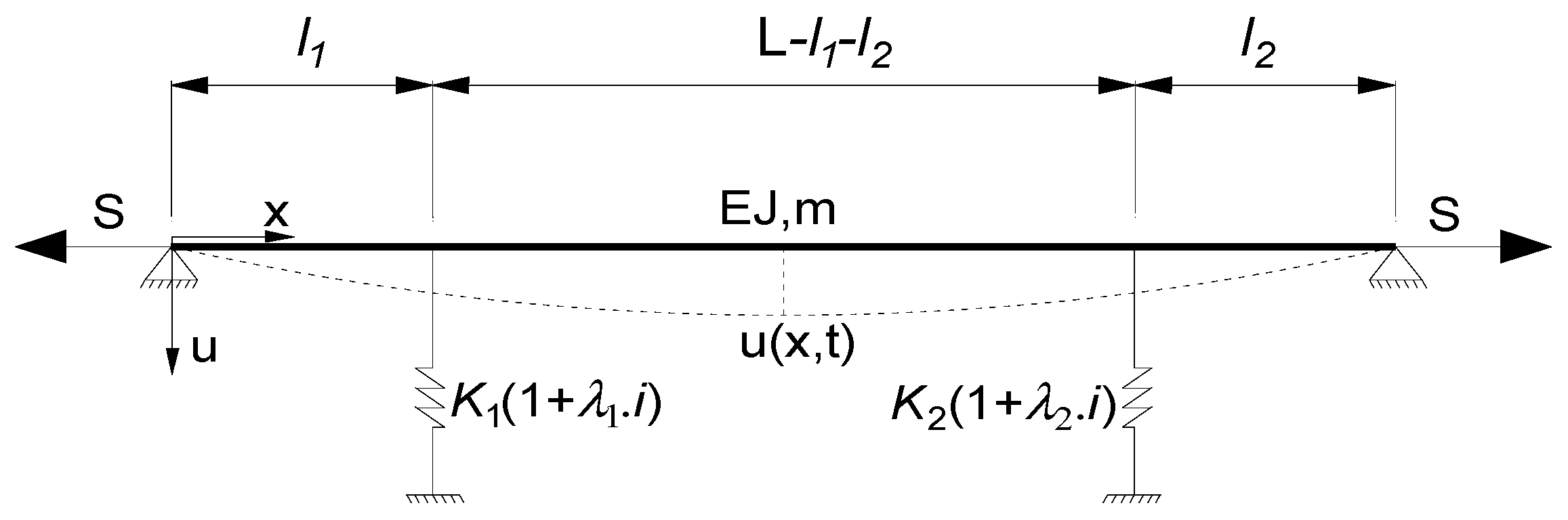
Figure 1 shows the considered taut cable model with two HDR dampers. The x-axis coincides with the longitudinal axis of the stay cable. The combination of two HDR dampers is located at l1 and l2 distances from each cable end. The mass per unit length of taut cable, cable length, bending stiffness and tension force in the stay cable is denoted as m, L, EI, and S, respectively. Since the rubber pads in the HDR dampers have the hysteretic characteristic, so the damping force does not depend on the frequency [14] and can be displayed as:
where Kj is the spring factor of jth damper; λj the material loss factor of jth damper; i2 = −1; u(lj,t)—the displacement of stayed-cable in location attached jth damper at time t.
It is assumed that the stay cable tension is much greater than its self-weight and the frictional force between the air and stay cable is negligible. The governing equation of in-plane cable motion can be expressed by:
where δ(.): the Dirac delta function is to simulate the concentrated damping force fj(t) (j = 1,2) located at x = lj.
By using the variables separation of Fourier, the result of Equation (2) can be described by:
The frequency equation of a stay cable with two HDR dampers can be derived by applying the boundary conditions and assuming equilibrium in the vertical direction at the positions where the dampers are attached, as shown in Equation (4). In which, η is the stay cable frequency at jth mode; setting k as a cable eigenvalue with complex form, k can be defined as Equation (5).
where is the cable natural frequency without damper devices; ξj, is the cable damping ratio at jth mode.
By substituting Equation (5) into Equation (4), the Equations (7) and (8) can be obtained by expanding and separating the real and imaginary parts.
where ; ; ; ; , ; ; ; ; ; . In which ∆, Φ1 and Φ2 are non-dimensional parameters, shown as following ; ;.
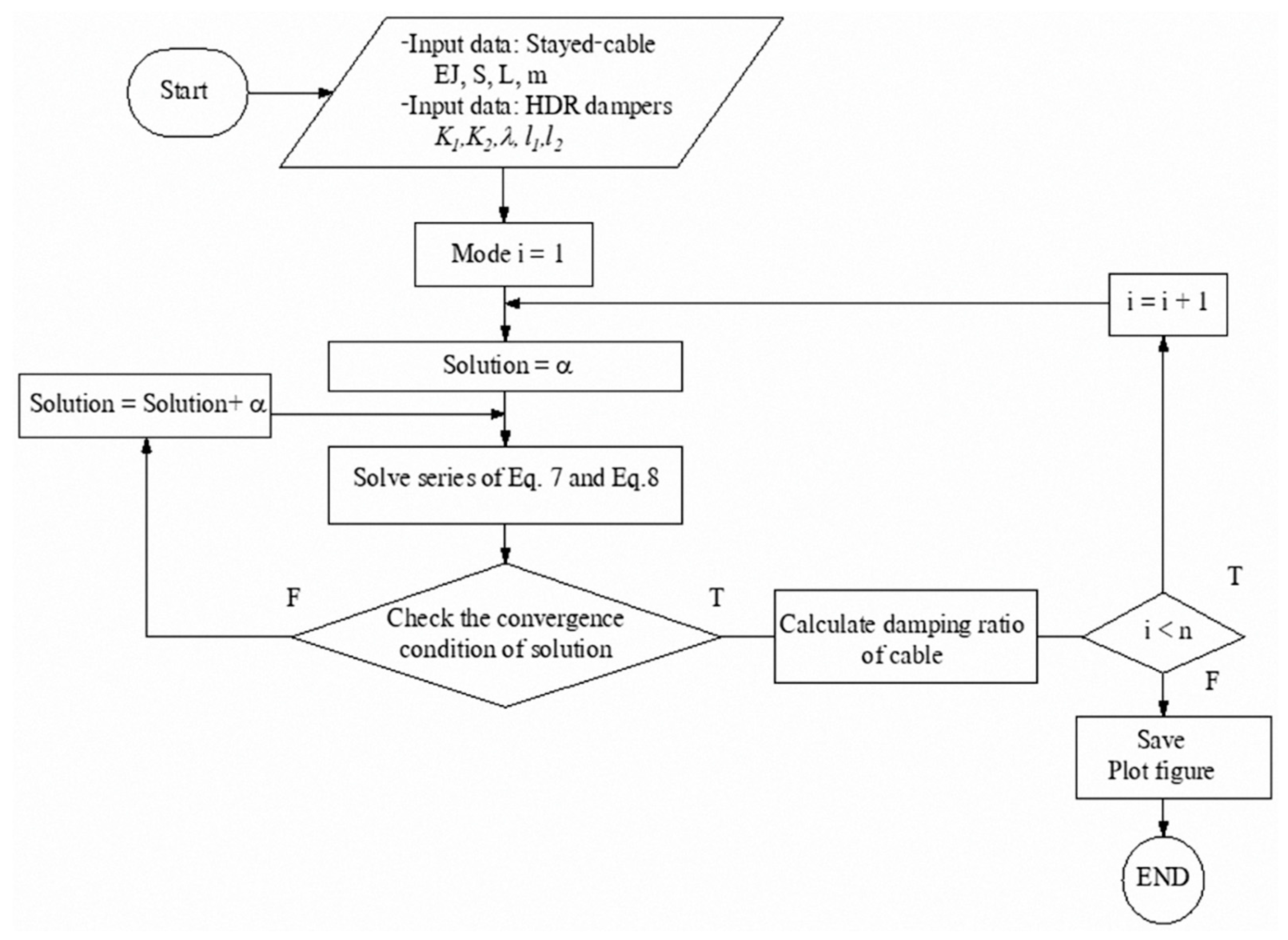
Due to the nonlinear nature of Equations (7) and (8), the iteration method is used to solve these equations. The algorithm to deal with Equations (7) and (8) illustrates in Figure 2.
3. Results and Discussion
3.1. Model Validation
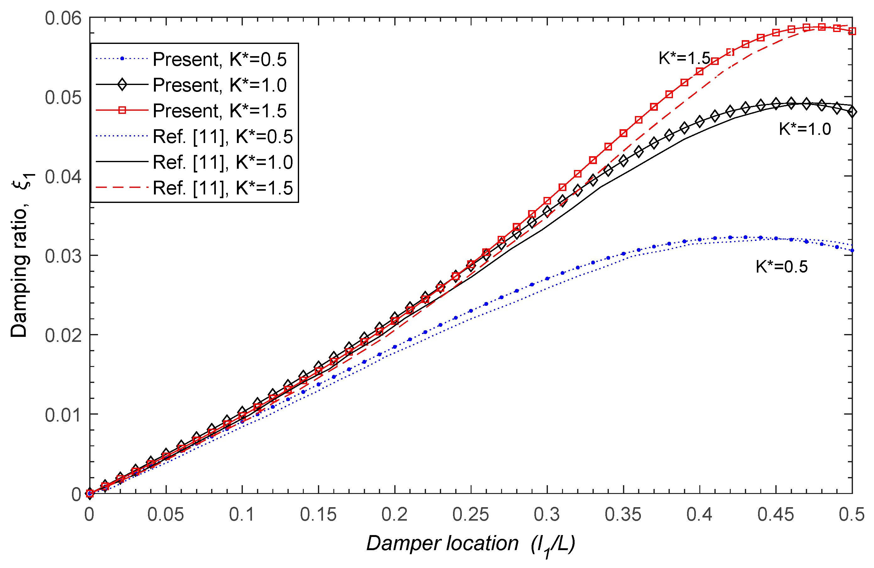
Due to the scarcity of experimental data of two HDR dampers, the model validation will be carried out using single HDR damper results of Cu and Han [11]. In this case, the system will be considered without a second HDR damper (K2 = 0, l2 = 0, λ2 = 0) whereas the other input parameters of the remained HDR damper is same to the work of [11]. Particularly, the bending stiffness of stay cable is considered in the present model compared to [11]. The non-dimensional spring factor is redefined by K* = K1.l1/S with a loss factor equal to 0.4 and the tension force, S = 2900 kN. The nonlinear equations 7–8 are solved using the algorithm shown in Figure 2 to obtain the damping ratio of HDR damper utilizing spring factor (K*) and installation position (l1/L) values varying from 0.5 to 1.5 and from 0 to 0.5, respectively [11]. Figure 3 presents the damping ratio computed by present model and [11] for different damper locations. In general, the damping ratio calculated by the present model shows high agreement with findings of Cu and Han [11]. The validation metrics of present model and [11] are shown in Table 1. The predicted value of the present model and [11] exhibits a high correlation. The correlation coefficient (CC) is approximate 0.999 for three different cases. In addition, the mean absolute gross error (EMAGE) and root mean square error (ERMSE) are very small, less than 1% for all cases (Table 1). The results obtained with the current model agree very well with [11] in terms of damping ratio value as well as the trend in the results for three different cases. In short, present model can be successfully utilized for approximate estimation of damping ratio for stay cable.
3.2. Effect of Spring Factor of HDR Dampers on First Modal Damping Ratio
To investigate the influence of two HDR dampers on improving cable damping, various properties of damping devices such as Kj-spring stiffness factor, λj-the loss factors, and the attached locations of dampers have been analyzed. For each HDR- damper parameter, the stay cable damping ratio is solved from the system of Equations (7) and (8). According to previous studies, the modal damping ratios do not depend much on the vibration modes for the stay cable installed HDR damper without rotational constraint at cable ends [7,10]. Therefore, the following sections present and discuss the effects of two HDR damper’s parameters on only the first modal damping ratio of stay cable.
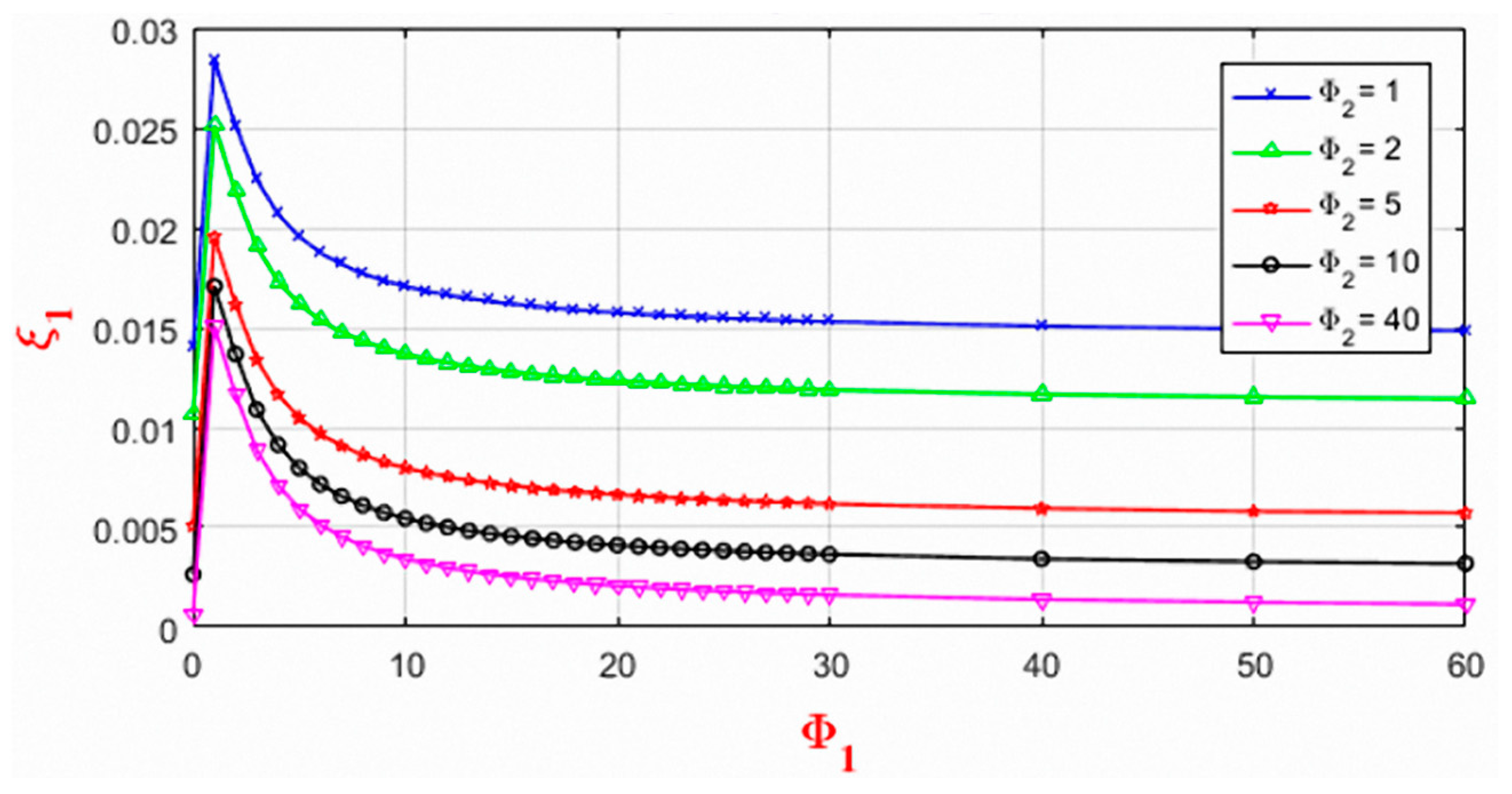
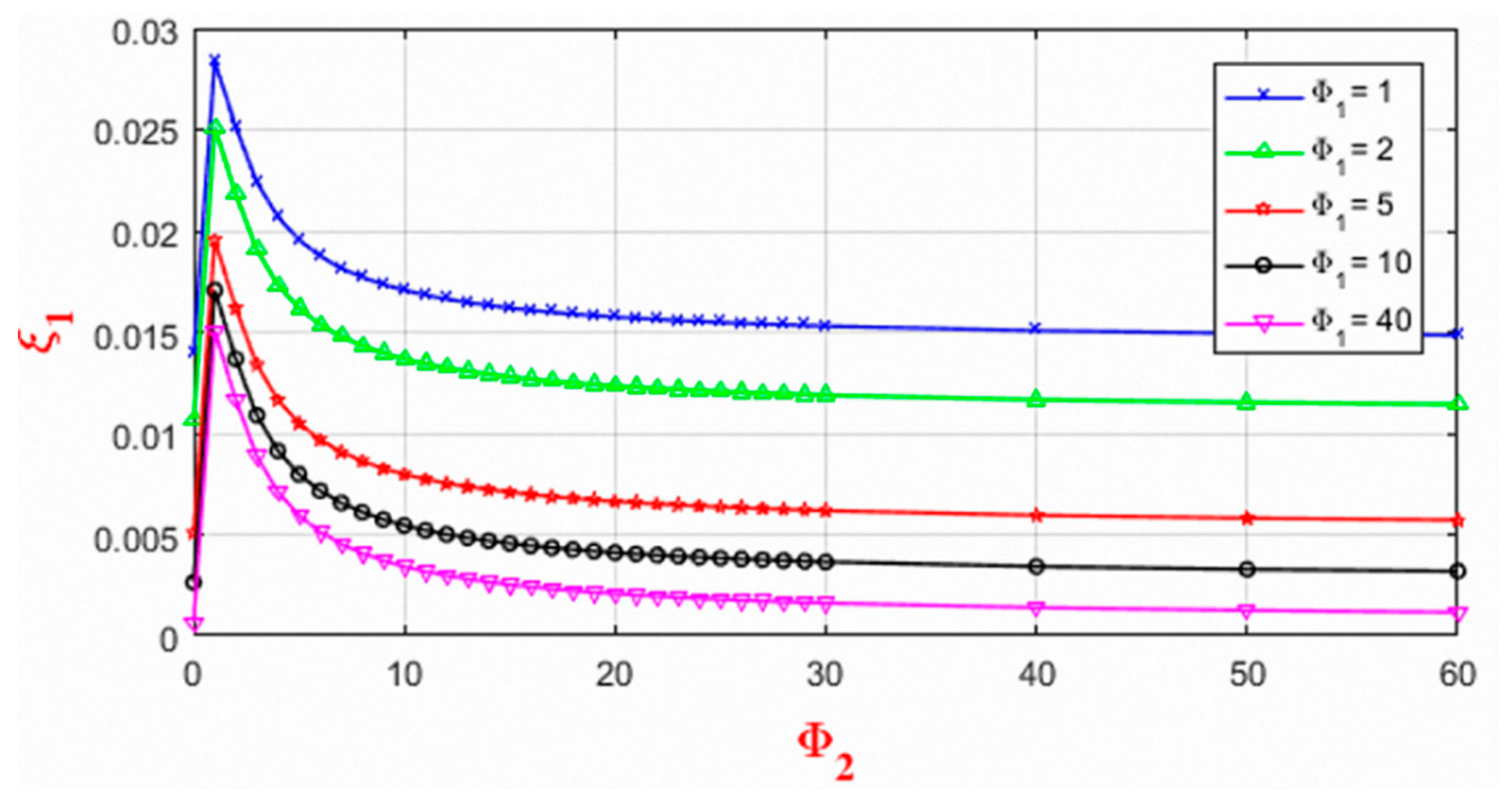
As discussed in Section 2, the spring factor of the damping device can be characterized by non-dimension coefficients Φi = Ki.L/π.S [13]. Where, L, is cable length and S, is cable tension, those are fixed for each stay cable. To figure out the relationship between Φi and Ki, a stay cable with tension force (S) of 3200 KN and L of 100 m are considered in this investigation. Figure 4 and Figure 5 illustrate the changes of 1st modal damping ratio (ξ1) with respect to the Φ1 and Φ2 corresponding to l1/L and l2/L equal to 0.03. In Figure 4, the Φ1 varies from 0 to 60, while the Φ2 values are fixed at 1, 2, 5, 10, 40, respectively. For each non-dimensional coefficient Φ2, the 1st modal damping ratio (ξ1) increases with the increase of Φ1 until reaching the maximum value. Then, the damping ratio (ξ1) decreases gradually, and the curve becomes flat. Therefore, for each value of Φ2, we can find an optimum value of Φ1 having the highest damping ratio. The similar results are illustrated in Figure 5. Consequently, the optimum parameters for two HDR dampers in the current study are Φ1 = 1 and Φ2 = 1 corresponding to K1 = 100 and K2 = 100, respectively. The maximum 1st modal damping ratio (ξ1max) may reach up to 0.0284. The detail of the results is summarized in Table 2 and Table 3.
3.3. Impact of Loss Factor (λ) of HDR Dampers on First Modal Damping Ratio
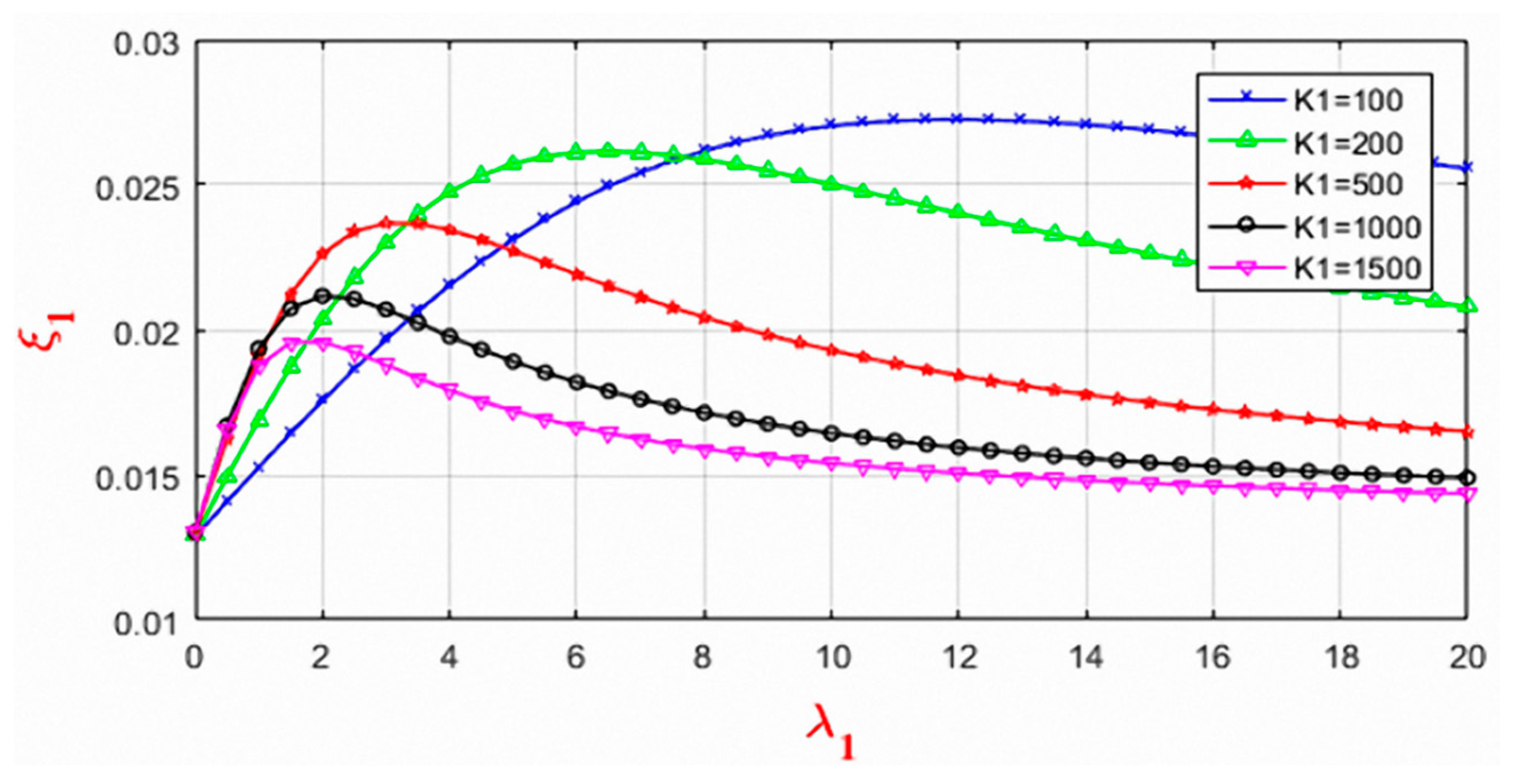
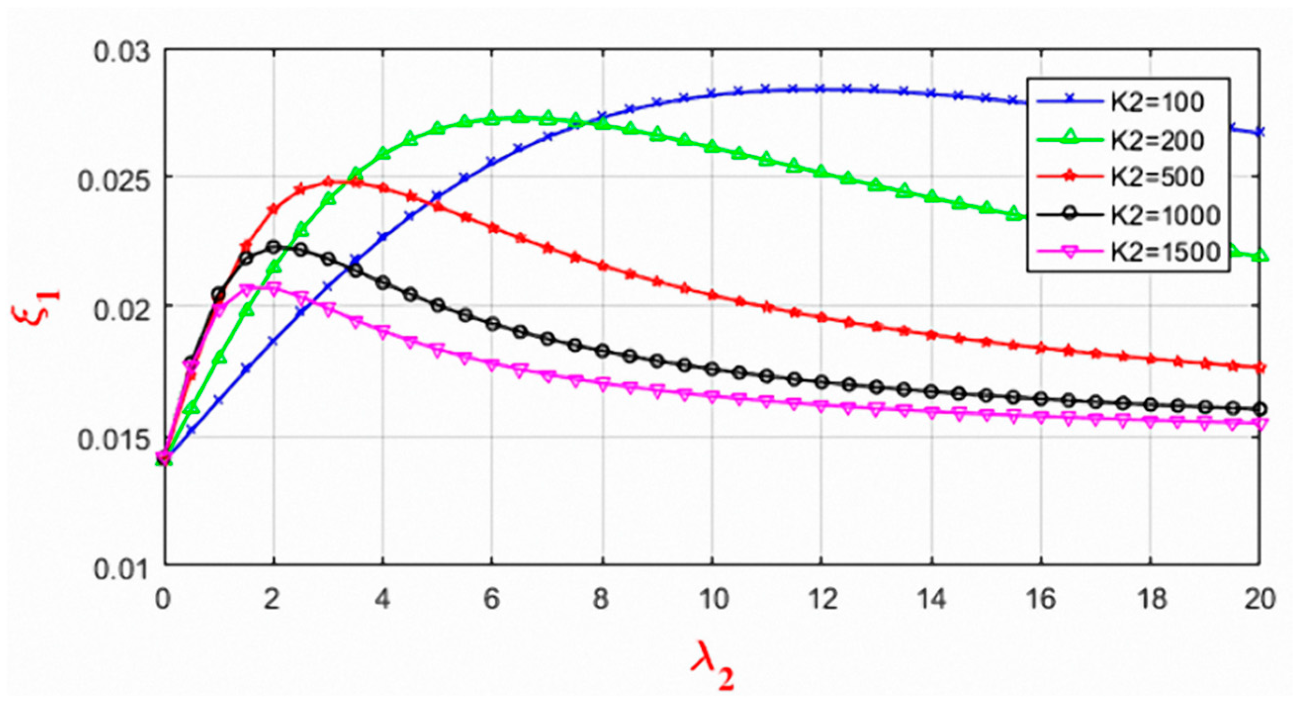
This section clarifies the effect of loss factor (λi) for different values of K1 and K2 on the first modal damping ratio (ξ1). The spring stiffness factors (K1 and K2) are varied for 100, 200, 500, 1000, and 1500. Figure 6 presents the relationship between damping ratio and loss factor for different values of K1. For each value of K1, there is an optimum value of loss factor (λ1) for which the damping ratio reaches the maximum value. For K1 = 100, the highest damping ratio 0.0284 is obtained at λ1 = 12. As the K1 value increases, the optimum value of the loss factor (λ1) decreases, and the magnitude of the highest damping ratio reduces from 0.0284 to 0.0207. The K2 and λ2 have a similar effect on cable damping ratio as shown in Figure 7. It is found that the 1st modal damping ratio is in direct proportion with the loss factor before reaching the optimum value. After that, the 1st modal damping ratio decreases as the loss factor increases. The optimum values of the 1st modal damping ratio are presented in Table 3 and Table 4.
3.4. Effect of Installation Position of Two HDR Dampers (l1/L, l2/L)
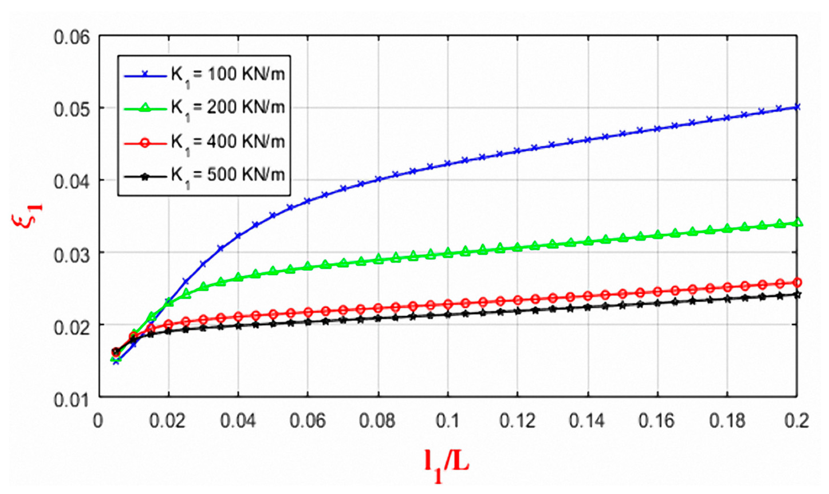
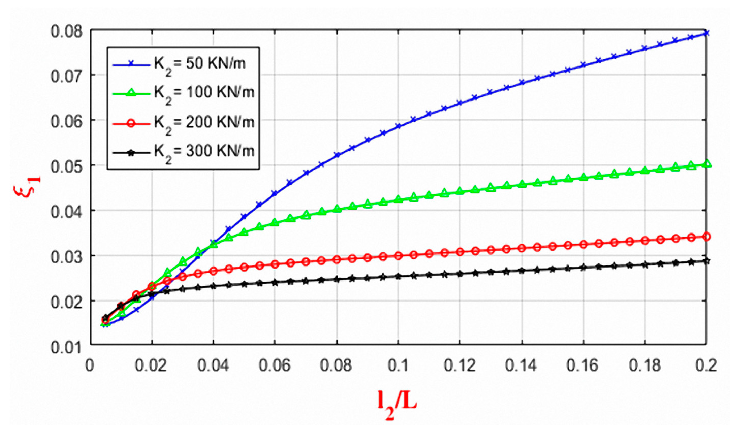
To figure out the impact of installation positions of two HDR dampers (l1/L, l2/L) on cable damping ratio, the installation position (l1/L) of dampers are varied from 0.01 to 0.2 for different values of K1 and K2. Figure 8 and Figure 9 show the relationship of ξ1 and l1/L for different values of K1 and K2. The damping ratio is directly proportional to the installation positions of HDR dampers. For any value of K1, the damping ratio increases with the increase of l1/L and l2/L. Furthermore, the values of damping ratio decrease with the increase of spring stiffness factors for an installation position of HDR dampers. The highest value the damping ratio 0.05 is found when l1/L equals to 0.2. However, if the installation position is too far from cable ends, it is hard to fabricate, install and maintain the dampers. Moreover, it affects the aesthetic aspect of the bridge as well. Usually, the HDR dampers are normally installed around a normalized value of 0.02 to 0.05 from the cable ends [13].
3.5. Effect of Bending Stiffness (EJ) of Stay Cable
The stay cables for long-span bridges have quite a big diameter. Especially, they are always covered by mortar or epoxy. As a result, the bending stiffness of the cable increases significantly. Therefore, cable bending stiffness should be considered during the analysis of cable vibration. Generally, the damping ratio of the stay cable depends on not only the spring factor, loss factor, installation position but also its bending stiffness, cable tension, and cable length.
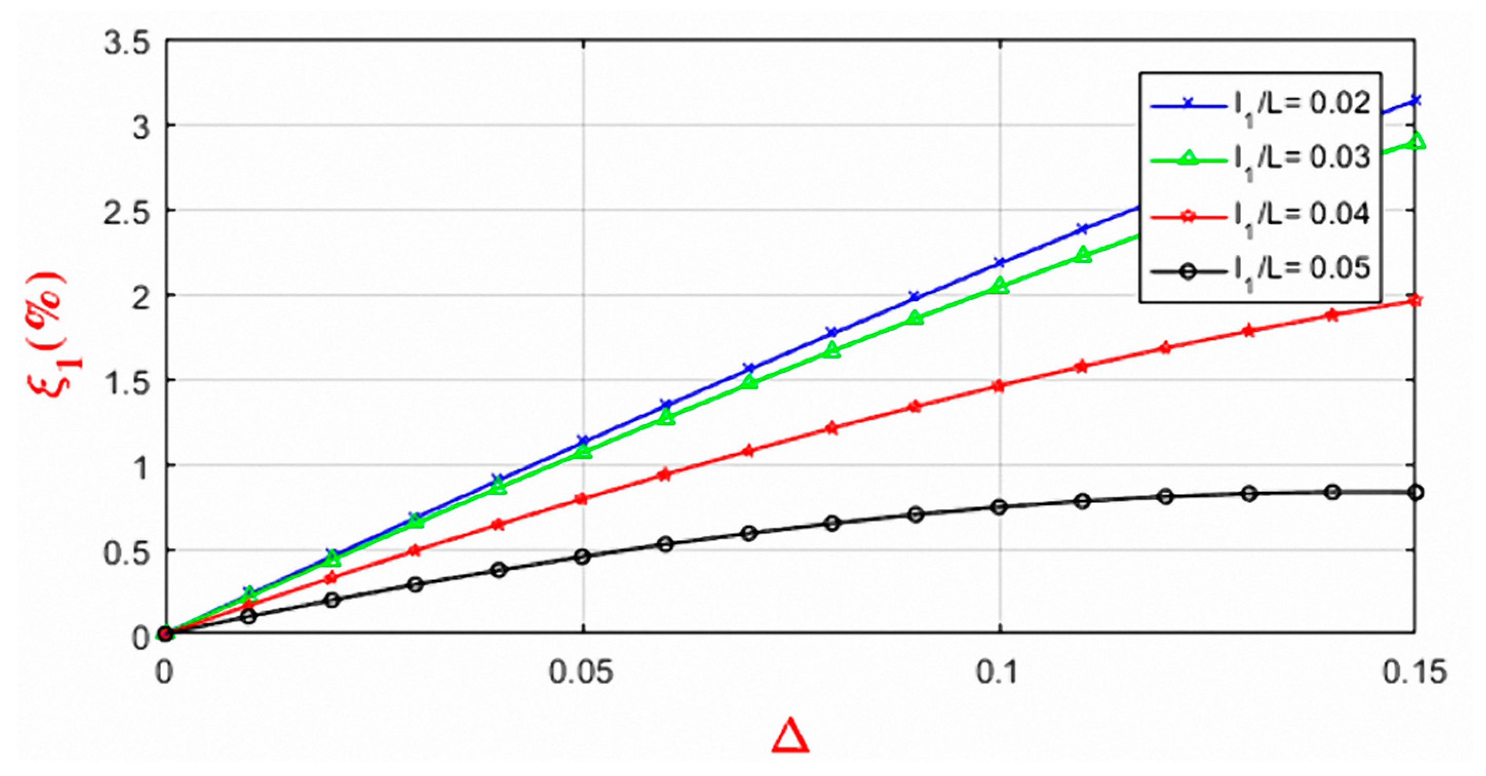
The non-dimensional parameter will be used for investigating the effect of bending stiffness. Parameter Δ reflects the cable stiffness and its sectional properties. The variation of the 1st modal damping ratio with non-dimensional parameter ∆ can be seen in Figure 10. In this Figure 10, the value of ∆ changes from 0 to 0.15 and the installation positions of HDR dampers varies from 0.02 to 0.05. Obviously, an increase in the damping ratio is directly proportional to Δ. The highest damping ratio is around 3.13% when the bending stiffness is taken into account in the current model.
3.6. Optimization Parameters for Two HDR Dampers
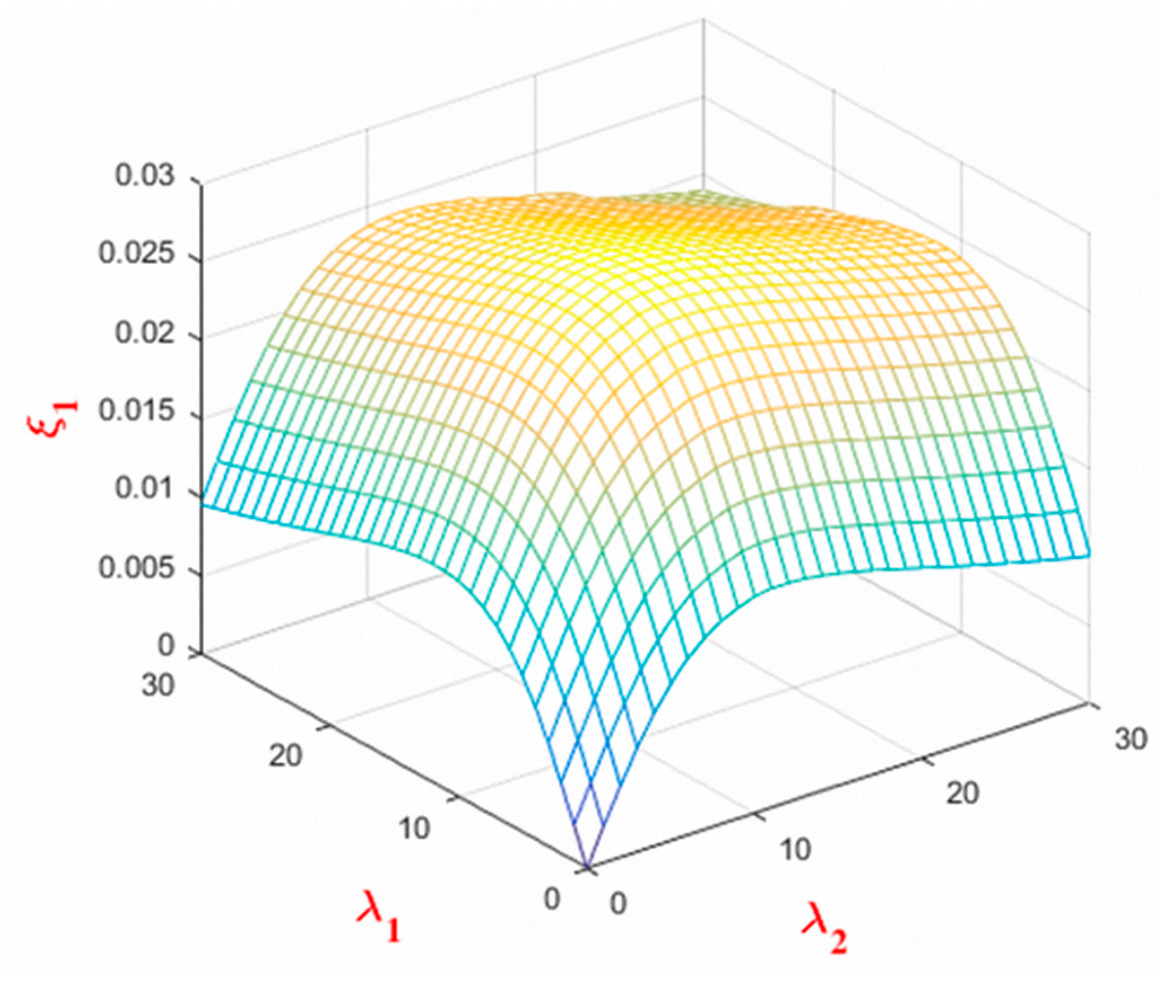
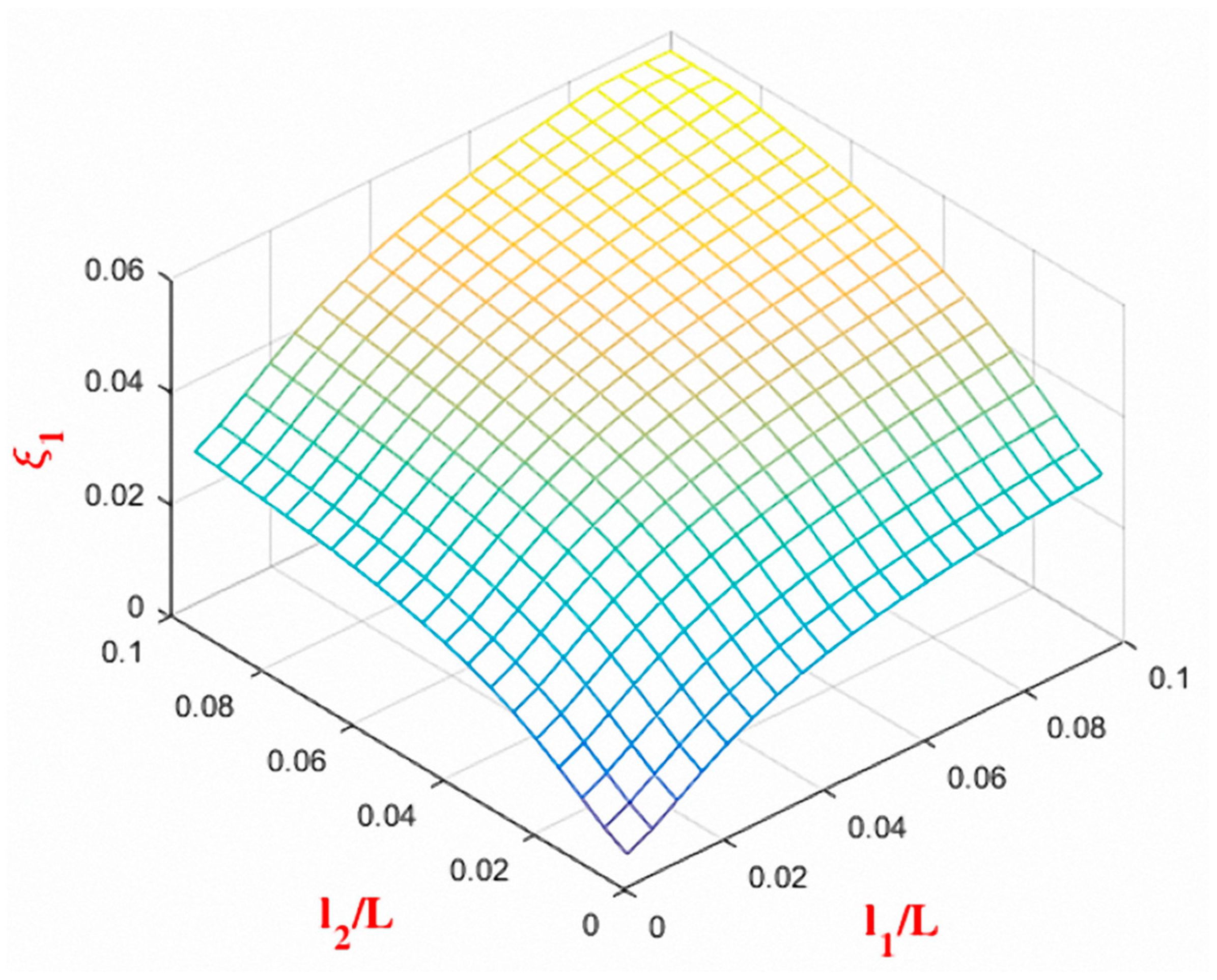
To evaluate the damping efficiency of two HDR dampers, the three-dimension relationship of the first modal damping ratio, loss factor, and installation position of dampers are explored in this section. Figure 11 presents the relationship between loss factors of two HDR dampers with the damping ratio. In this analysis, the installation position of two HDR dampers is fixed at 0.03. From the figure, it is evident that loss factors of dampers have a significant influence on the damping ratio of the dampers. As the loss factors of the dampers increases, the damping ratio increases as well. The highest value of damping ratio is obtained for a loss factor value of 12. On the other hand, the relationship between the installation positions of two HDR dampers with the damping ratio is presented in Figure 12. As the magnitude of installation position increases from the cable ends, the higher damping ratio of the cable increases as well. Furthermore, the peak value of the damping ratio is found for an installation position (l/L) of 0.1 from the cable ends.
4. Conclusions
This paper already investigated the effect of combined two HDR dampers on1stmodal damping ratio of stay cable under considering cable bending stiffness. The theoretical model for evaluating cable damping with two HDR dampers has been proposed. The comparative analysis of results elucidated that the parameters such as loss factor, spring factor, and installation positions of dampers have much effect on the cable damping ratio. The conclusions obtained from this study are as follow:
- Theoretical formulation for evaluating the modal damping ratio of stay cable with two HDR dampers has been proposed and validated.
- For a stay cable with fixed values of tension (S) and cable length (L), the optimum spring factor value of HDR dampers can be obtained when the parameter Φi (Ki.L/π.S) becomes 1.
- Loss factors play a significant role in the damping efficiency of HDR dampers. There is always an optimum value for the loss factor. By varying the spring factor, the optimum loss factor value can be figured out.
- Based on the present analysis, it is found that the damping ratio is directly proportional to the installation positions of HDR dampers. The larger the value of installation distance from the cable ends, the damping ratio also becomes higher. In addition, cable damping is also directly proportional to its bending stiffness.
- Present model can be an effective tool for evaluating the stay cable damping with two HDR-dampers. Designer can choose appropriate values among various design parameters to obtain the highest damping ratio.
Author Contributions
Conceptualization, D.T.N. and D.H.V.; methodology, D.T.N. and D.H.V.; software, D.T.N., D.H.V. and M.N.H.; validation, D.T.N., D.H.V. and M.N.H.; formal analysis, D.T.N. and D.H.V.; investigation, D.T.N. and D.H.V.; writing—original draft preparation, D.T.N., D.H.V. and M.N.H.; writing—review and editing, D.T.N., D.H.V. and M.N.H. All authors have read and agreed to the published version of the manuscript.
Funding
This research is funded by the University of Danang, University of Science and Technology.
Institutional Review Board Statement
Not applicable.
Informed Consent Statement
Not applicable.
Data Availability Statement
All data, models, and codes to support the findings of this study are available from the corresponding author upon request.
Conflicts of Interest
The authors declare no conflict of interest.
References
- Hung, V.D.; Thao, N.D. A Further Study on Stay Cable Galloping under Dry Weather Condition. In Lecture Notes in Civil Engineering; Springer: Singapore, 2020; Volume 54. [Google Scholar] [CrossRef]
- Vo-Duy, H.; Nguyen, C.H. Mitigating Large Vibrations of Stayed Cables in Wind and Rain Hazards. Shock. Vib. 2020, 2020, 5845712. [Google Scholar] [CrossRef]
- Vo, H.D.; Katsuchi, H.; Yamada, H.; Nishio, M. A wind tunnel study on control methods for cable dry galloping. Front. Struct. Civ. Eng. 2016, 10, 72–80. [Google Scholar] [CrossRef]
- Pacheco, B.M.; Fujino, Y.; Sulekh, A. Estimation curve for modal damping in stay cables with viscous damper. J. Struct. Eng. 1993, 119, 1961–1979. [Google Scholar] [CrossRef]
- Takano, H.; Ogasawara, M.; Ito, N.; Shimosato, T.; Takeda, K.; Murakami, T. Vibrational damper for cables of the Tsurumi Tsubasa Bridge. J. Wind Eng. Ind. Aerodyn. 1997, 69–71, 807–818. [Google Scholar] [CrossRef]
- Nakamura, A.; Kasuga, A.; Arai, H. The effects of mechanical dampers on stay cables with high-damping rubber. Constr. Build. Mater. 1998, 12, 115–123. [Google Scholar] [CrossRef]
- Fujino, Y.; Hoang, N. Design Formulas for Damping of a Stay Cable with a Damper. J. Struct. Eng. 2008, 134, 269–278. [Google Scholar] [CrossRef]
- Main, J.A.; Jones, N.P. Free Vibrations of Taut Cable with Attached Damper. I: Linear Viscous Damper. J. Eng. Mech. 2002, 128, 1062–1071. [Google Scholar] [CrossRef] [Green Version]
- Hoang, N.; Fujino, Y. Analytical Study on Bending Effects in a Stay Cable with a Damper. J. Eng. Mech. 2007, 133, 1241–1246. [Google Scholar] [CrossRef]
- Hoang, N.; Fujino, Y. Combined Damping Effect of Two Dampers on a Stay Cable. J. Bridge Eng. 2008, 13, 299–303. [Google Scholar] [CrossRef]
- Cu, V.H.; Han, B. High-damping rubber damper for taut cable vibration reduction. Aust. J. Struct. Eng. 2005, 16, 283–291. [Google Scholar] [CrossRef]
- Le, L.X.; Katsuchi, H.; Yamada, H. Damping of Cable with HDR Damper Accounting for Restraint Boundary Conditions. J. Bridge Eng. 2020, 25, 04020105. [Google Scholar] [CrossRef]
- de Sá Caetano, E. Cable Vibrations in Cable-Stayed Bridges, 9th ed.; IABSE (International Association for Bridge and Structural Engineering): Zürich, Switzerland, 2007. [Google Scholar]
- Krenk, S. Vibrations of a taut cable with an external damper. J. Appl. Mech. 2000, 67, 772–776. [Google Scholar] [CrossRef]
- Chen, L.; Sun, L.; Nagarajaiah, S. Cable vibration control with both lateral and rotational dampers attached at an intermediate location. J. Sound Vib. 2016, 377, 38–57. [Google Scholar] [CrossRef]
- Zhou, P.; Li, H. Modeling and control performance of a negative stiffness damper for suppressing stay cable vibrations. Struct. Control Health Monit. 2016, 23, 764–782. [Google Scholar] [CrossRef]
- Cu, V.H.; Han, B.; Pham, D.H. Tuned mass-high damping rubber damper on a taut cable. KSCE J. Civ. Eng. 2017, 21, 928–936. [Google Scholar] [CrossRef]
- Di, F.; Sun, L.; Chen, L. Suppression of vortex-induced high-mode vibrations of a cable-damper system by an additional damper. Eng. Struct. 2021, 242, 112495. [Google Scholar] [CrossRef]
- Caracoglia, L.; Jones, N.P. Damping of taut-cable systems: Two dampers on a single stay. J. Eng. Mech. 2007, 133, 1050–1106. [Google Scholar] [CrossRef]
- Xu, Y.L.; Yu, Z. Mitigation of three-dimensional vibration of inclined sag cable using discrete oil dampers. II: Application. J. Sound Vib. 1998, 214, 675–693. [Google Scholar] [CrossRef]
- Tabatabai, H.; Mehrabi, A.B. Design of mechanical viscous dampers for stay cables. J. Bridge Eng. 2000, 5, 114–123. [Google Scholar] [CrossRef]
- Nguyen, D.T.; Vo, D.H. A Study on Combination of Two Friction Dampers to Control Stayed-cable Vibration under considering its Bending Stiffness. Lect. Notes Civ. Eng. 2020, 54, 87–93. [Google Scholar]
- Di, F.; Sun, L.; Chen, L. Cable vibration control with internal and external dampers: Theoretical analysis and field test validation. Smart Struct. Syst. 2020, 26, 575–589. [Google Scholar]
- Zhou, H.; Xiang, N.; Huang, X.; Sun, L.; Xing, F.; Zhou, R. Full-scale test of dampers for stay cable vibration mitigation and improvement measures. Struct. Monit. Maint. 2018, 5, 489–506. [Google Scholar]
- Lu, L.; Duan, Y.F.; Spencer, B.F., Jr.; Lu, X.; Zhou, Y. Inertial mass damper for mitigating cable vibration. Struct. Control Health Monit. 2017, 24, e1986. [Google Scholar] [CrossRef]
- Wang, Z.H.; Xu, Y.W.; Gao, H.; Chen, Z.Q.; Xu, K.; Zhao, S.B. Vibration control of a stay cable with a rotary electromagnetic inertial mass damper. Smart Struct. Syst. 2019, 23, 627–639. [Google Scholar]
- Huang, Z.; Hua, X.; Chen, Z.; Niu, H. Performance evaluation of inerter-based damping devices for structural vibration control of stay cables. Smart Struct. Syst. 2019, 23, 615–626. [Google Scholar]
Figure 1.
A stay cable with two HDR dampers.

Figure 2.
Model algorithm.

Figure 3.
Comparison of present model and [11].
Figure 3.
Comparison of present model and [11].

Figure 4.
Relationship of Φ1 and ξ1.

Figure 5.
Relationship between Φ1, Φ2 and ξ1.

Figure 6.
Relationship of (λ1; ξ1) and K1.

Figure 7.
Relationship between λ2 and ξ2 for different values of K2.

Figure 8.
Relationship of ξ1 and l1/L with different K1.

Figure 9.
Relationship of ξ1 and l2/L with different K2.

Figure 10.
Relationship between Δ and ξ1% with different l1/L.

Figure 11.
Loss factors optimization for two HDR dampers.

Figure 12.
Installation positions optimization for two HDR dampers.


Table 1.
Validation metrics between present study and [11].
Table 1.
Validation metrics between present study and [11].
| Validation Metrics | K* = 1.5 | K* = 1.0 | K* = 0.5 |
|---|---|---|---|
| CC | 0.9997 | 0.9994 | 0.9992 |
| RMSE | 0.0014 | 0.0011 | 0.0007 |
| EMAGE | 0.0002 | 0.0002 | 0.0001 |
Table 2.
Maximum damping ratio ξ1max for each Φ1.
| Φ2 | 1 | 2 | 5 | 10 | 40 |
|---|---|---|---|---|---|
| ξ1max | 0.0284 | 0.0251 | 0.0195 | 0.0171 | 0.0151 |
| Φ1 | 1 | 1 | 1 | 1 | 1 |
Table 3.
Maximum damping ratio ξ1max for each Φ2.
| Φ1 | 1 | 2 | 5 | 10 | 40 |
|---|---|---|---|---|---|
| ξ1max | 0.0284 | 0.0251 | 0.0195 | 0.0171 | 0.0151 |
| Φ2 | 1 | 1 | 1 | 1 | 1 |
Table 4.
Damping ratio ξ1max with λ1.
| K1 | 100 | 200 | 500 | 1000 | 1500 |
|---|---|---|---|---|---|
| ξ1max | 0.0284 | 0.0273 | 0.0248 | 0.0223 | 0.0207 |
| λ1 | 12 | 6 | 3 | 2 | 1.5 |
Publisher’s Note: MDPI stays neutral with regard to jurisdictional claims in published maps and institutional affiliations. |
© 2021 by the authors. Licensee MDPI, Basel, Switzerland. This article is an open access article distributed under the terms and conditions of the Creative Commons Attribution (CC BY) license (https://creativecommons.org/licenses/by/4.0/).
Share and Cite
MDPI and ACS Style
Nguyen, D.T.; Vo, D.H.; Haque, M.N. Theoretical Investigation on the Impact of Two HDR Dampers on First Modal Damping Ratio of Stay Cable. Appl. Sci. 2021, 11, 10985. https://0-doi-org.brum.beds.ac.uk/10.3390/app112210985
AMA Style
Nguyen DT, Vo DH, Haque MN. Theoretical Investigation on the Impact of Two HDR Dampers on First Modal Damping Ratio of Stay Cable. Applied Sciences. 2021; 11(22):10985. https://0-doi-org.brum.beds.ac.uk/10.3390/app112210985
Chicago/Turabian StyleNguyen, Duy Thao, Duy Hung Vo, and Md. Naimul Haque. 2021. "Theoretical Investigation on the Impact of Two HDR Dampers on First Modal Damping Ratio of Stay Cable" Applied Sciences 11, no. 22: 10985. https://0-doi-org.brum.beds.ac.uk/10.3390/app112210985
Note that from the first issue of 2016, this journal uses article numbers instead of page numbers. See further details here.