
A Hybrid Nonlinear Active Control Strategy Combining Dry Friction Control and Nonlinear Velocity Compensation Control

1
Sino-French Engineer School, Beihang University, Beijing 100191, China
2
Laboratory of Complex Systems, Beihang University, Beijing 100191, China
3
College of Mechanical Engineering, Beijing University of Technology, Beijing 100124, China
*
Author to whom correspondence should be addressed.
Appl. Sci. 2021, 11(24), 11670; https://0-doi-org.brum.beds.ac.uk/10.3390/app112411670
Submission received: 3 November 2021
/
Revised: 2 December 2021
/
Accepted: 3 December 2021
/
Published: 9 December 2021
(This article belongs to the Special Issue Vibration Control and Applications)
Abstract
:Friction dampers are widely used in structural vibration suppression in various fields, such as aeronautics, astronautics, robotics, precision manufacturing, etc. Traditional friction dampers are mainly used in a passive way to optimize vibration suppression with an immutable pressure around certain excitation. In this manuscript, a hybrid control strategy by considering both the friction force in the active control law and a nonlinear velocity compensation force is put forward: First, the normal force applied on the friction damper was adjusted to ensure its vibration reduction effect under different excitation for a first passive control; second, the active control law was established by combining the dry friction force and the velocity control force in the state space; lastly, the stability of the nonlinear control law was determined by Lyapunov criterion. Numerical simulations were conducted on a three degree-of-freedom system (3-DOF) based on the proposed hybrid control strategy, to show the control efficiency in vibration suppression and economic efficiency in energy input into the system. Simulation results showed that the proposed control law could reduce the amplitude of the active control force by about 5% without degrading the control efficiency.
1. Introduction
Vibration control is one of the most important subjects in aeronautics, astronautics, robotics, precision manufacturing, etc. Flexible structures are increasingly applied in aeronautics and astronautics, such as the solar panels of satellites, and their light weight and flexible properties have caused numerous vibration problems because of their low natural frequency. Many accuracy problems have been induced by vibration in the robotics field. For example, if the vibration cannot be well controlled in the process of manufacturing workpieces with a robotic arm, the workpieces and processing tools would be considerably damaged, and product quality would be greatly degraded. In precision manufacturing, vibration will also introduce great machining errors and affect machining accuracy.
Among various vibration suppression methods, friction damper is a commonly used tool [1]. The widely used control methods with friction dampers are mainly divided into three types: passive dampers, semi-active dampers, and active dampers [2,3,4]. Passive dampers benefit from the fact that the energy dissipated by this type of damper does not change with the size and frequency of the load [5]. This type of damper has been widely used in civil engineering [6,7,8], aircraft [9], aeroengine [10,11,12], automobile [13,14], etc. However, the passive friction dampers can only be optimized for a unique given excitation. In order to ameliorate the effect of friction damper under different excitation, semi-active dampers were proposed. With the development of smart materials, some semi-active dampers then emerged. Semi-active damping control can reserve the reliability of passive dampers while presenting a better control effect [15]. Synchronous switch damping based on piezoelectric materials is also a commonly used semi-active damping control method [16]. Magnetorheological (MR) dampers, as a type of semi-active damper, are employed in civil engineering to reduce the absorb seismic energy [7]. However, with the increasing requirements for structural vibration control in different fields such as precision machining, passive and semi-active control methods can no longer fully meet the needs. Active friction control can adjust the friction force according to the functional conditions of the structure, and hence, it can provide a better vibration suppression effect. Ohzono et al. [17,18,19,20,21,22,23] developed a type of morphing surface whose friction coefficient changes with its wrinkle amplitude. The wrinkle amplitude is controlled by the internal stress mismatch of layered material, and the friction can then be controlled in an active way. Murashima [24] developed a metal morphing surface with a varying friction coefficient that depends on the lubrication conditions, pressure, and speed. These studies on realizing the change of friction make friction control possible. Therefore, active friction control is a valuable subject.
Many researchers have also taken friction into consideration when designing active control laws. Heckl and Abrahams [25] proposed an active feedback control of a friction-driven oscillator. The feedback control law is specifically dedicated to unstable friction-induced vibrations. Zhou and Li [26] proposed a finite-time robust adaptive sliding mode control of a system with friction compensation, with the stability of the proposed control law proved by the Lyapunov criterion, and the efficiency proved by experience. Zou et al. [27] proposed an adaptive sliding mode-based position tracking control for systems with nonlinear friction compensation. This control law is proved experimentally to have a better performance than the commonly used PI feedback control. In most of these studies, friction is considered to be an item that affects the system performance, and active control force compensation is required. In some other research, semi-active friction is considered with some active control law. Hernán et al. [28] have studied analytically, numerically, and experimentally semi-active friction tendons under control law based on velocity feedback and force feedback. The velocity feedback control law shows more precision, and the force feedback control law is more effective for limiting the displacement under large loads. Marcelo Braga [29] has designed a damper assembling auxiliary mass damper and semi-active friction damper, and this damper has shown effectiveness on multi-degree-of-freedom vibratory systems. These studies show the possibility to consider friction as an active control force.
Friction is an effective energy dissipation method in vibration suppression and can also be introduced as an active control force in the design of the control law. In addition, general active control requires continuous external energy input, and the control law combined with friction is expected to reduce the external energy input. This study combined an external force with an artificially introduced friction force to control the vibration of the system. With a simple three degree-of-freedom (3-DOF) oscillator system, a nonlinear control law was designed, and the Lyapunov criterion was applied to observe the stability of the control law. Numerical simulations proved the effectiveness of the proposed nonlinear control law.
This paper is structured as follows: In Section 2, the governing motion equation, along with the corresponding state-space transformations of the 3-DOF oscillator system, are first established. The control law combining varying dry friction force and active control force is then established in the state space. The stability of the control is further proved with the Lyapunov criterion. Section 3 presents the numerical simulation results of the proposed control law, including the time domain response and the frequency domain response of the system under no external control force, pure dry friction force control, pure active force control, and the hybrid control law proposed in this manuscript. A discussion of the simulation results is provided at the end of Section 3. In Section 4, the general conclusions are drawn.
2. Theoretical Aspects
All symbols used in this section can be found with physical meanings in Table A1 in Appendix A.
2.1. Governing Motion Equation of a 3-DOF Model
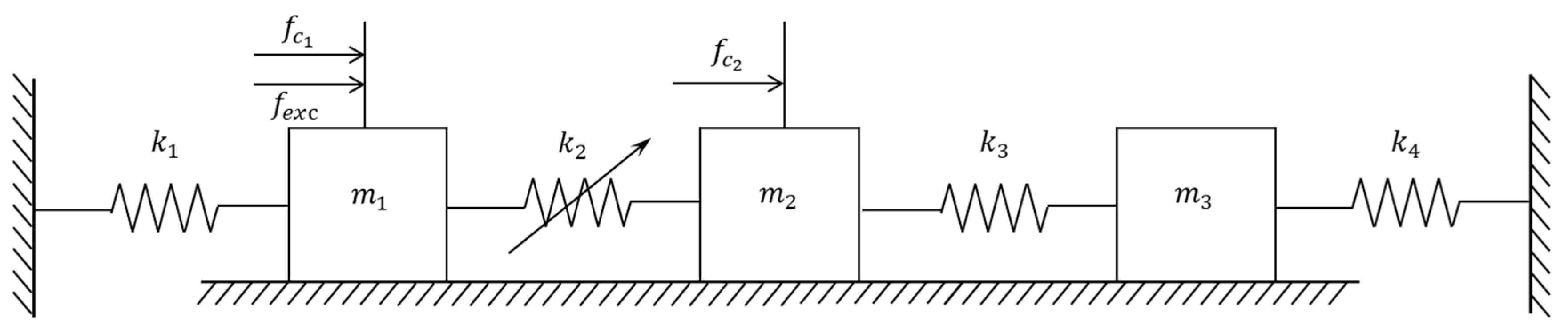
A 3-DOF mass stiffness model was employed to explain the theoretical aspects of this paper, and the nonlinear friction force was applied between and , as shown in Figure 1.
The governing equation of the above model is expressed as
In the matrix form, the governing motion equation is written as
where is the mass matrix of the system, ;
is the stiffness matrix of the system;
is the displacement vector of the system;
is the friction vector;
, is the friction coefficient and is the normal force applied on the interface;
is a sign function, which returns 1 for all x > a and −1 for all x < a;
is the exterior excitation vector;
is the active control force vector, and the corresponding matrix form is written as
2.2. A Nonlinear Hybrid Control Strategy Combining Dry Friction and Active Control Force
2.2.1. Governing Motion Equation in the First State Space
Since the friction force is a function of relative velocity and relative displacement , in order to facilitate the design of control law, the above physical space is transformed into a state space where the relative displacements are set as new variables in the new governing equation.
Supposing and , then the friction force will be decoupled in the new state space, only engaged in the equation of , while disappearing in the equation of .
The governing equation in the new state space is expressed as
The corresponding matrix form is written as
where is the displacement vector in the newly defined state space;
is the mass matrix in the newly defined state space;
is the stiffness matrix in the newly defined state space;
is the friction vector in the newly defined state space;
is the exterior excitation vector in the newly defined state space;
is the active control force vector in the newly defined state space, and the corresponding matrix form is written as
The transformation matrix bring the physical coordinates into the state space is defined as
where , which is reversible, and vice versa, .
Employing this transformation matrix, the physical space can be easily transformed into state space. By replacing by , and left multiplying by in Equation (3), we have
where
- ;
- ;
- ;
- ;
- .
2.2.2. Control Law Design in the Second State Space
The control law is designed in a second, new state space by choosing
Let us note
where ;
;
.
This control law was proposed to amplify the state space velocity with an exponential function, so this control law is denoted as “nonlinear velocity compensation control” in the following text.
The active control force in the state-space is defined by
where is the coefficient matrix of active control force, which is positive definite.
By utilizing the transformation matrix, the active control force physical space is given by
In this study, the active control force was applied on the dry friction surface; that is to say, the active control force was applied on and . Thus, the distribution matrix is defined as Equation (14) as follows:
where .
2.2.3. Stability of the Proposed Nonlinear Control Law
The stability of nonlinear control law is generally determined by the Lyapunov criterion. In this framework, a generalized energy function is required to be defined, which is the Lyapunov function. For an arbitrary vector , if and , the system is asymptotically stable.
In order to check the stability of the above control law, the Lyapunov function of the controlled system motion equation is investigated in this section.
The new variable in the second state space is noted as
The new governing motion equation, along with the control law in the second state space, is found to be
According to Equation (6), we have
Since is positive definite, and the dry friction distribution matrix is semi-positive definite, we can conclude that . According to the Lyapunov criterion, the system is asymptotically stable.
3. Numerical Simulations
3.1. Description of Physical Parameters Employed in the Model
The values of the parameters employed in the simulation are listed in Table 1.
The parameters of the 3-DOF oscillator are given in Table 1, and the first three natural frequencies of this model without control are , , and . When the amplitude of the friction force tends to infinity, the 3-DOF oscillator turns into a 2 DOF oscillator, and its natural frequencies are and .
3.2. Simulation Results
In the following analysis, the control effect of the following three different control laws is provided: (1) the pure friction force control law; (2) the pure active force control law; (3) the hybrid active force and friction force control law.
3.2.1. Frequency Response
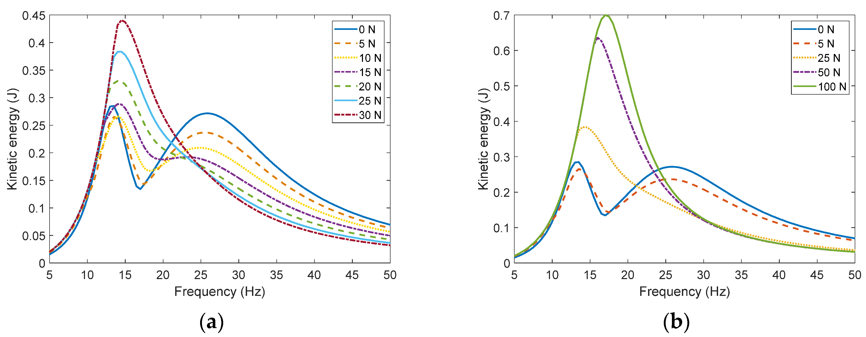
For a system with passive friction dampers, the frequency responses of the 3-DOF system with different friction force amplitude are shown in Figure 2.
It can be seen from Figure 2 that dry friction can alter the amplitude and frequency around the resonances. As the amplitude of dry friction increases, the frequency of the first resonance peak increases, and the frequency of the second resonance peak decreases. With the increase in the dry friction amplitude, the peak value of these two resonances peak will at first decrease and then increase, as shown in Figure 2. According to reference [30], the peak value of a frictional system would at first decrease and then increase, which is in accordance with the results shown in Figure 2. In order to achieve a better passive friction damping effect, the normal force applied to the damper needs to be adapted to the system requirements
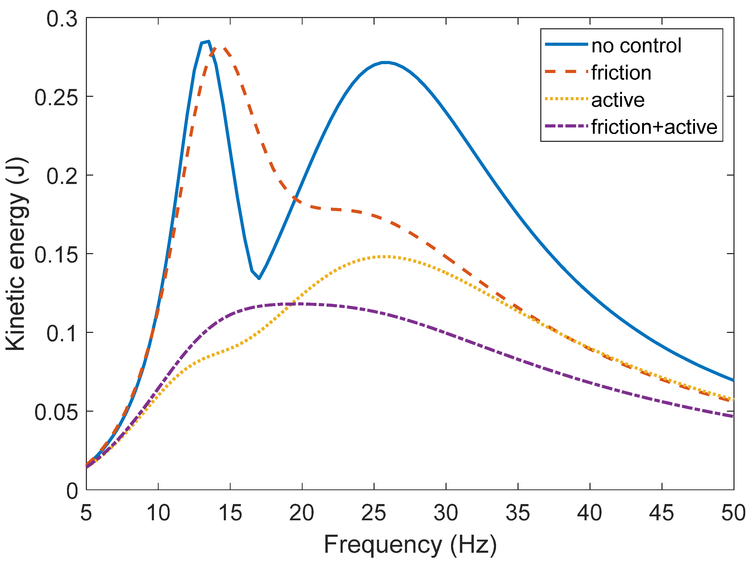
The frequency response of the initial noncontrolled system, the system involving only active friction damper, the system involving only active control force, and the system involving the proposed hybrid control strategy are, respectively, shown in Figure 3.
It can be seen from Figure 3 that for the system using only an active friction damper, the kinetic energy amplitude of the first resonance is slightly reduced, and the frequency is slightly increased. The kinetic energy amplitude of the second resonance is visibly reduced. By comparing the blue line with Figure 2, it can be concluded that active friction damping and passive friction damping have similar characteristics for the 3-DOF oscillator; that is to say, the damping effect for low-frequency vibration is poor, while the damping effect for high-frequency vibration is better. For the system containing only an active control force, the system can achieve a better control effect in the low-frequency band. The peak value of the first resonant is greatly reduced. However, the control effect becomes worse for high-frequency excitation. Another observation is that the system with pure active control force provides no significant shift in the resonant frequencies, which is in accordance with theoretical formulations. For the system with the proposed nonlinear hybrid control, the kinetic energy amplitude around both resonances is greatly reduced. Although the performance around the first resonance frequency is slightly worse than the control effect that only includes the active control force, the performance around the second resonance still justifies its obvious advantages. The proposed control law can greatly attenuate the system’s kinetic energy amplitude for both resonance zones, resulting in a global better dynamic performance in the interested frequency band.
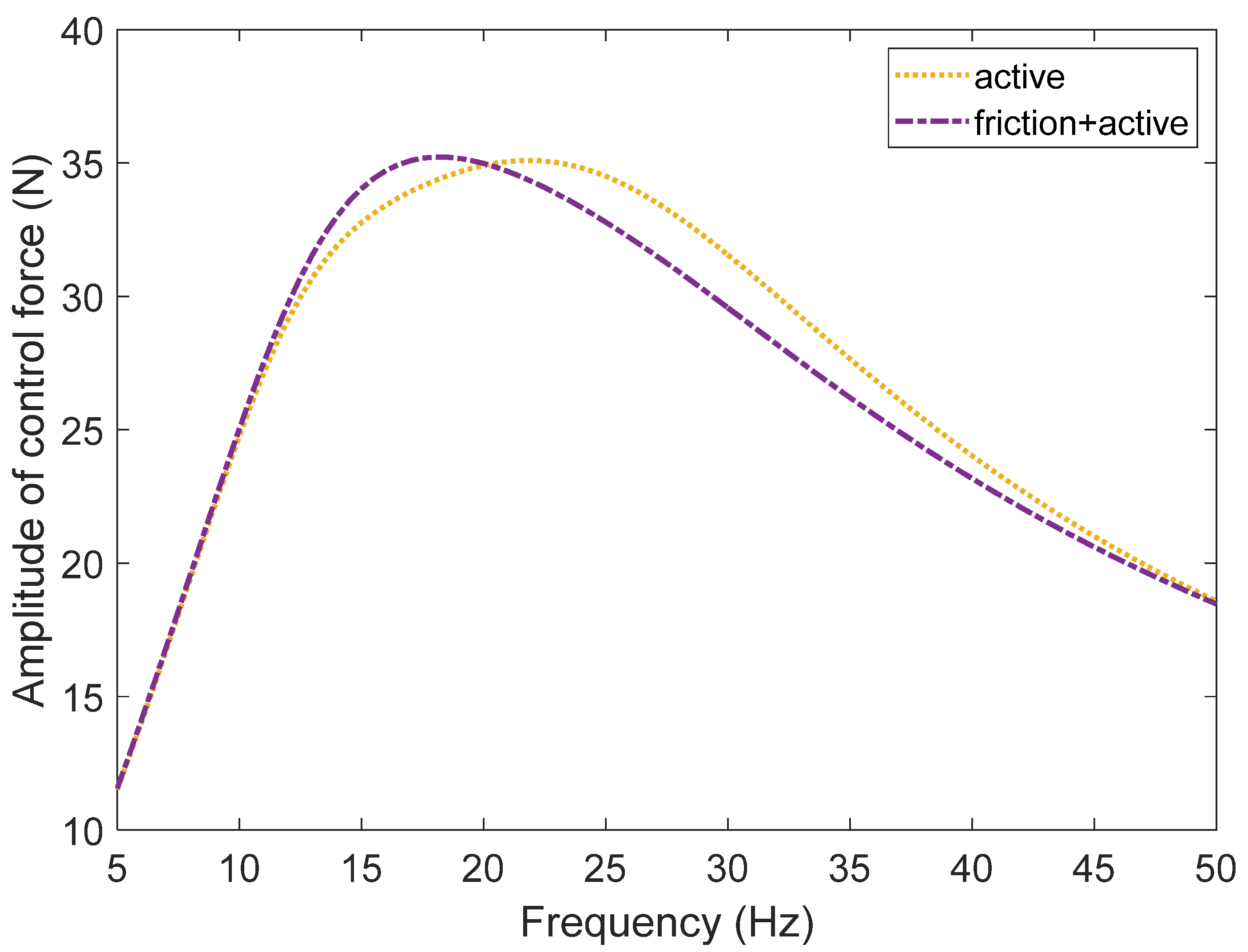
In order to verify the effect of the control law in reducing the active control force, the amplitudes of control forces introduced in the control law for the system with pure active control and the proposed nonlinear velocity compensation control were calculated, as shown in Figure 4.
It can be seen from Figure 4 that around the first resonance frequency, the nonlinear velocity compensation control law proposed in this manuscript increases the amplitude of the active control force by a maximum of 4%, while around the second resonance frequency, the amplitude of active control force decreases by about 6%. Therefore, the proposed nonlinear hybrid control law can achieve the initial purpose of reducing the external energy input for frequency above 20 Hz for this 3-DOF system.
3.2.2. Time Response of Certain Frequencies
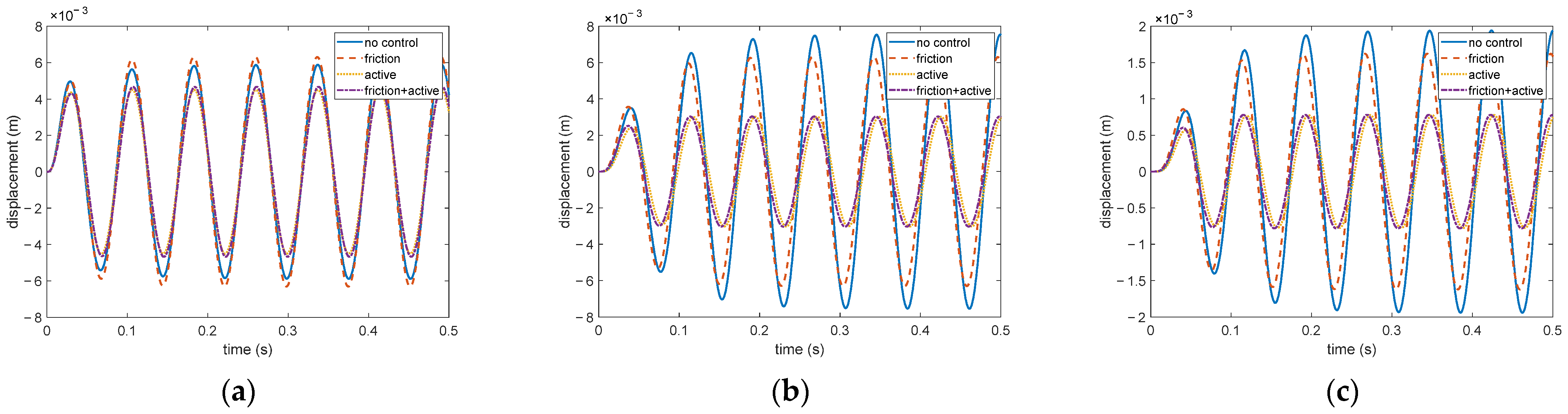
The transient time response of the system is also an important reference for investigating the control law effect. Time response curves of the 3-DOF system around the first resonance frequency of the aforementioned systems are depicted in Figure 5, and the excitation frequency is set to 13 Hz.
Since friction dampers only exist between and , the dynamic performance of these two masses is more sensible to friction forces. By comparing the time-domain responses of the system without control force and with active friction damping, it can be seen that active friction damping makes the amplitude of the two connected masses more even, and at the same time, it will slightly reduce the amplitude of . However, as concluded from Figure 3, the damping effect of active friction damping is not obvious at this frequency. The active control force can obviously reduce the amplitude of all these three masses. At the same time, the two curves without active control force both approach the steady state after two or three cycles, while the curve with active control force only needs one cycle to reach the steady vibration, so the active control force shows faster response speed. Under this excitation, the effects of active control and the proposed nonlinear velocity compensation control show similar response speed and characteristics.
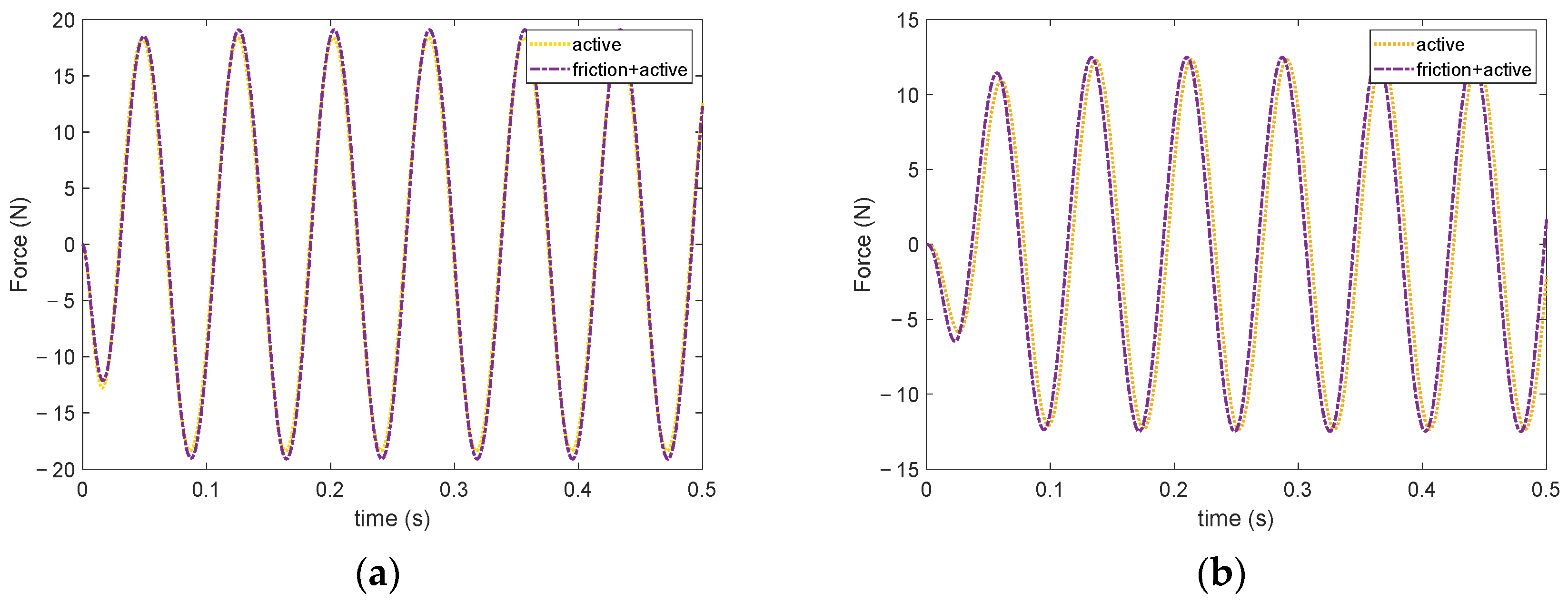
Figure 6 illustrates the time histories of active control force of pure active control and that of this hybrid control.
When observing Figure 6, it can be found that the proposed nonlinear hybrid control method will slightly increase the active control force on both and . The active control forces of the hybrid control applied on and are about 3% more than that of the pure active control, which accords with the analysis of Figure 4. Therefore, in the low-frequency band, the proposed nonlinear hybrid control method will increase the energy input of the external active control force.
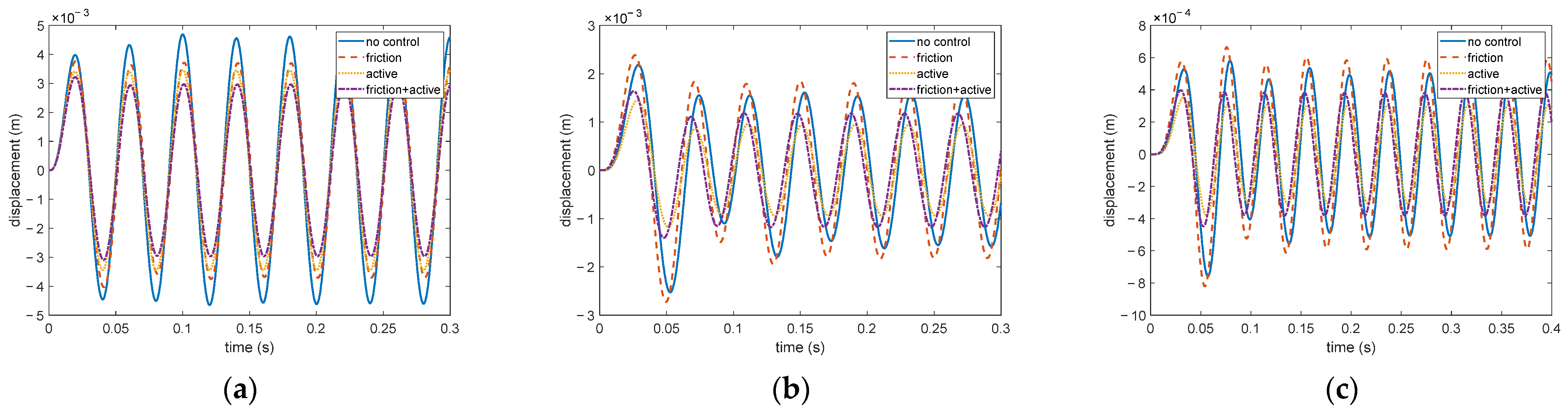
Figure 7 shows the displacement time histories of the three masses under the excitation frequency of the second resonance frequency; that is to say, the excitation force frequency is 25 Hz.
By comparing the three figures in Figure 7, it can be seen that, around the second resonance, the amplitude of in the noncontrolled system is much larger than that of and . The amplitude of and are closer for the system with control. By comparing the time histories of the system with active friction damping and that with the proposed nonlinear velocity compensation control, it can be seen that the control effects of the system with active control for and are slightly better than that of the proposed hybrid control, while the advantage of the proposed nonlinear hybrid control for can quite well compensate this disadvantage. The control effect of the active friction control is visibly worse than the proposed hybrid control. At the same time, the existence of friction force between and could make the amplitudes of the two masses more even.
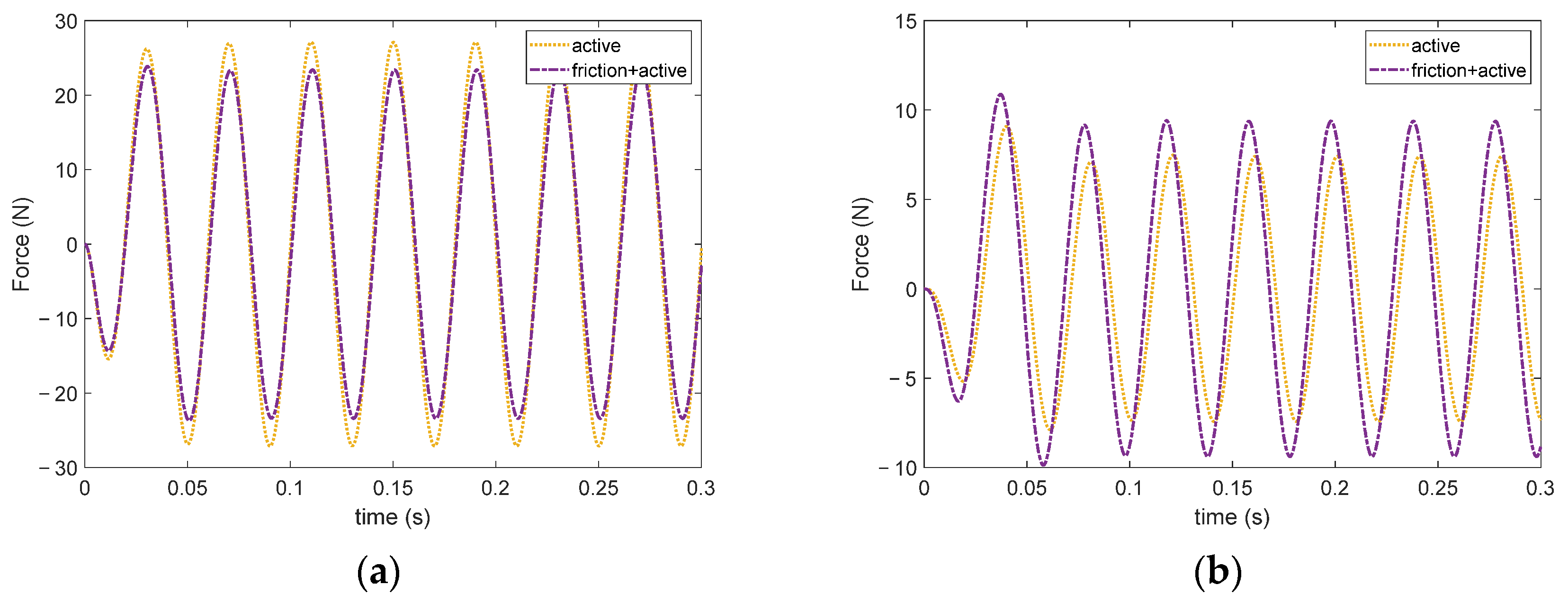
Similarly, Figure 8 has shown the advantage of the proposed nonlinear velocity compensation control in reducing the input energy of the active control force.
From Figure 8a, it can be found that the proposed nonlinear hybrid control method can obviously reduce the active control force applied on . By inspecting Figure 8b, it can be seen that the control force of the proposed hybrid control is slightly larger than the pure active control. The amplitude of active control force applied on and reduces by about 8%, which accords with the analysis of Figure 4. Therefore, under high-frequency excitation, the designed hybrid control method has a better effect on reducing the input energy.
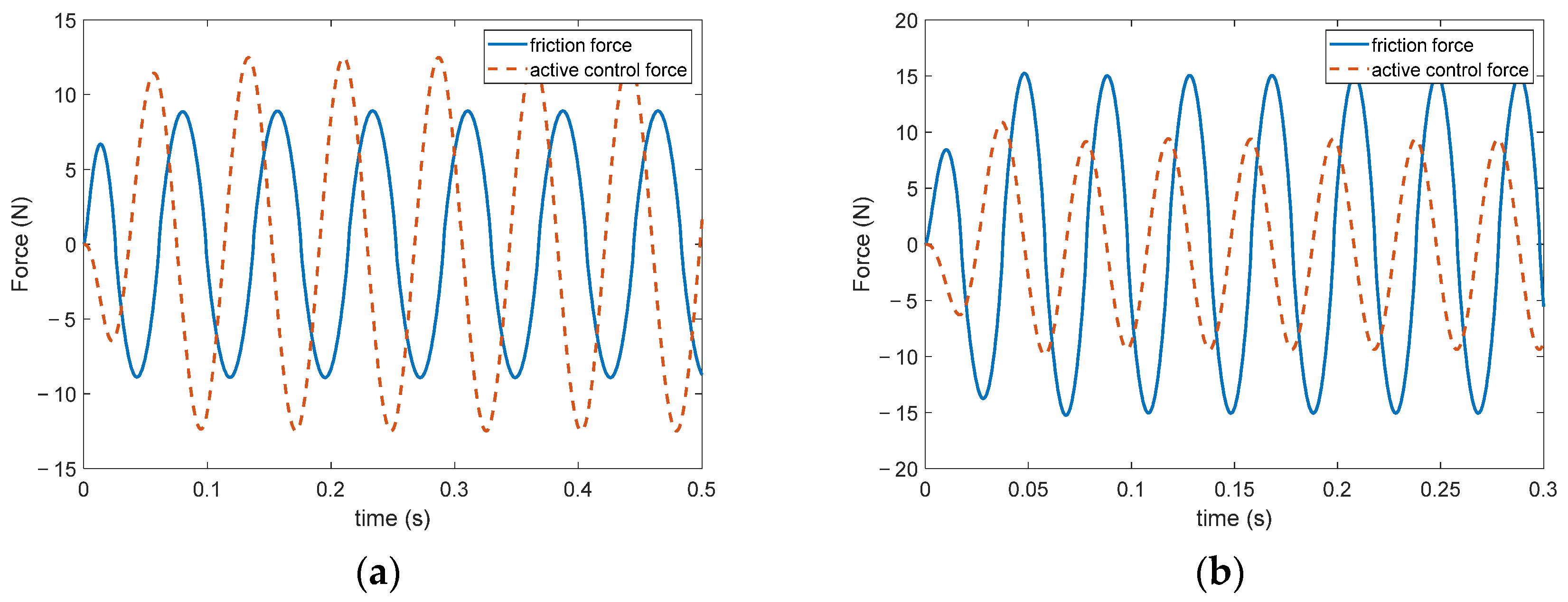
In order to investigate the effect of the friction force in the proposed hybrid control law, the time histories of the friction force under excitation at and are shown in Figure 9. The time responses of are also drawn in Figure 9 as reference.
From Figure 9, it can be seen that the amplitude of friction force under excitation is larger than that under excitation. Therefore, under excitation, the friction force is able to dissipate more energy than under , which explains why under excitation, the proposed hybrid control law can reduce the input energy.
By comparing the time histories of the system around these two resonant frequencies, the following conclusions can be drawn: under low-frequency excitation, the proposed nonlinear velocity compensation control law shows better control effect in response amplitude than the pure active friction damping control, and slightly worse effect than the pure active control; under higher-frequency excitation, the proposed hybrid control strategy shows better control effects than the other two methods and reduce the energy requirement, compared with the pure active control.
3.3. Discussion
It can be observed from Figure 3 that under harmonic excitation, active control has a better control effect on the system under low-frequency excitation. This is in accordance with the theoretical formulations since the excitation vibration period on this occasion is larger or similar to the response time of the system under active control. However, as the excitation frequency increases, and since the response time does not change under linear active control law, the system would not respond in time, thus resulting in the deterioration of the control effect. The control effect of dry friction in a low-frequency band is not as good as that in a high-frequency band. Therefore, the combination of these two control methods would better suppress the vibration and, in the meanwhile, reduce the input energy of the active control force at high frequencies, as shown in Figure 4 and Figure 8.
It should be noted that the control efficiency of this proposed hybrid control law could still be improved under low-frequency excitation.
4. Conclusions
This paper proposed a nonlinear hybrid control law combining active friction damping and active control force, and simulations were conducted on a 3-DOF system. The following conclusions can be drawn from this study:
(1) The proposed hybrid control is stable according to the Lyapunov criterion;
(2) It is difficult to deal with the system vibration under different excitation frequencies at the same time using regular friction damping methods, and pure active control methods at high frequency are not efficient in terms of response speed and input energy. The hybrid control law proposed in this study can provide quite a good compromise;
(3) The proposed nonlinear hybrid control law shows better control effects in steady-state kinetic energy of the system under different frequency excitation;
(4) Under high-frequency excitation, the proposed hybrid control strategy reveals the advantage of reducing the input energy of active control force, compared with the pure active control method.
Author Contributions
Conceptualization, X.H. and X.Y.; methodology, X.H., D.Y. and X.Y.; validation, D.Y.; formal analysis, X.H., D.Y. and X.Y.; investigation, X.H., D.Y. and X.Y.; resources, D.Y.; data curation, D.Y.; writing—review and editing, X.H., D.Y. and X.Y.; visualization, D.Y.; supervision, X.H. and X.Y.; project administration, X.H. and X.Y. All authors have read and agreed to the published version of the manuscript.
Funding
This research was supported by the National Natural Science Foundation of China, Grant Number 52105083, the major project of aeroengines and gas turbines, Grant Number J2019-IV-023-0091, the Innovation Centre for Advanced Aviation Power, Grant Number HKCX2020-02-016, and the National Natural Science Foundation of China, Grant Number 11804015.
Institutional Review Board Statement
Not applicable.
Informed Consent Statement
Not applicable.
Data Availability Statement
There is no data reported.
Conflicts of Interest
The authors declare no conflict of interest.
Appendix A

Table A1.
Nomenclature List.
| Symbol | Variable Type | Explanation |
|---|---|---|
| Matrix | Coefficient matrix of active control force | |
| Matrix | Distribution matrix of active force | |
| Scalar | Friction force | |
| Scalar | Active control force on mass | |
| Scalar | Excitation force | |
| Scalar | Normal force of friction | |
| Vector | Active control force vector | |
| Vector | State-space active control force vector | |
| Vector | Exterior excitation vector | |
| Vector | State-space exterior excitation vector | |
| Vector | Friction vector | |
| Vector | State-space friction vector | |
| Scalar | Stiffness coefficient of spring | |
| Matrix | Stiffness matrix | |
| Matrix | State-space stiffness matrix | |
| Scalar | Mass | |
| Scalar | Mass of | |
| Matrix | Mass matrix | |
| Matrix | State-space mass matrix | |
| Matrix | Coordinate transformation matrix from physical space to state space | |
| Scalar | Physical displacement of mass | |
| Vector | Physical displacement vector | |
| Scalar | State-space displacement | |
| Vector | State-space displacement vector | |
| Vector | State-space coordinate of control law | |
| Vector | Displacement vector in second state-space | |
| Scalar | Power parameter in control law | |
| Matrix | Coefficient of friction in control law | |
| Scalar | Friction coefficient |
References
- Jaisee, S.; Yue, F.; Ooi, Y.H. A state-of-the-art review on passive friction dampers and their applications. Eng. Struct. 2021, 235, 112022. [Google Scholar] [CrossRef]
- Symans, M.D.; Charney, F.A.; Whittaker, A.S.; Constantinou, M.C.; Kircher, C.A.; Johnson, M.W.; McNamara, R.J. Energy Dissipation Systems for Seismic Applications: Current Practice and Recent Developments. J. Struct. Eng. 2008, 134, 3–21. [Google Scholar] [CrossRef] [Green Version]
- Habibi, A.; Chan, R.W.; Albermani, F. Energy-based design method for seismic retrofitting with passive energy dissipation systems. Eng. Struct. 2013, 46, 77–86. [Google Scholar] [CrossRef]
- Saaed, T.E.; Nikolakopoulos, G.; Jonasson, J.-E.; Hedlund, H. A state-of-the-art review of structural control systems. J. Vib. Control. 2015, 21, 919–937. [Google Scholar] [CrossRef]
- Housner, G.W.; Bergman, L.A.; Caughey, T.K.; Chassiakos, A.G.; Claus, R.O.; Masri, S.F.; Skelton, R.E.; Soong, T.T.; Spencer, B.F.; Yao, J.T.P. Structural Control: Past, Present, and Future. J. Eng. Mech. 1997, 123, 897–971. [Google Scholar] [CrossRef]
- Perkowski, W. Dry friction damper for supercritical drive shaft. J. KONES 2016, 23, 389–396. [Google Scholar] [CrossRef]
- Lenggana, B.W.; Ubaidillah, U.; Imaduddin, F.; Choi, S.-B.; Purwana, Y.M.; Harjana, H. Review of Magnetorheological Damping Systems on a Seismic Building. Appl. Sci. 2021, 11, 9339. [Google Scholar] [CrossRef]
- Mrad, C.; Titirla, M.D.; Larbi, W. Comparison of Strengthening Solutions with Optimized Passive Energy Dissipation Systems in Symmetric Buildings. Appl. Sci. 2021, 11, 10103. [Google Scholar] [CrossRef]
- Sun, Y.; Yuan, J.; Pesaresi, L.; Denimal, E.; Salles, L. Parametric Study and Uncertainty Quantification of the Nonlinear Modal Properties of Frictional Dampers. J. Vib. Acoust. 2020, 142, 1–23. [Google Scholar] [CrossRef]
- Sazhenkov, N.; Semenova, I.; Nikhamkin, M.; Semenov, S. A substructure-based numerical technique and experimental analysis of turbine blades damping with underplatform friction dampers. Procedia Eng. 2017, 199, 820–825. [Google Scholar] [CrossRef]
- Gao, S.; Wang, Y. An Evaluation Method for Dry Friction Damping of Ring Damper in Gas Turbine Engines under Axial Vibration. Aerospace 2021, 8, 302. [Google Scholar] [CrossRef]
- Gastaldi, C.; Gola, M. A Method to Minimize the Effort for Damper–Blade Matching Demonstrated on Two Blade Sizes. Appl. Sci. 2021, 11, 5171. [Google Scholar] [CrossRef]
- Herzog, L.; Augsburg, K. Study on Friction in Automotive Shock Absorbers Part 1: Friction Simulation Using a Dynamic Friction Model in the Contact Zone of an FEM Model. Vehicles 2021, 3, 212–232. [Google Scholar] [CrossRef]
- Grzesikiewicz, W.; Makowski, M. Semi-Active System of Vehicle Vibration Damping. Appl. Sci. 2021, 11, 4577. [Google Scholar] [CrossRef]
- Garrido, H.; Curadelli, O.; Ambrosini, D. Semi-active friction tendons for vibration control of space structures. J. Sound Vib. 2014, 333, 5657–5679. [Google Scholar] [CrossRef]
- Richard, C.; Guyomar, D.; Audigier, D.; Ching, G. Semi-Passive Damping Using Continuous Switching of a Piezoelectric Device; International Society for Optics and Photonics: Bellingham, WA, USA, 1999; pp. 104–111. [Google Scholar]
- Shimomura, M.; Ohzono, T. Ordering of microwrinkle patterns by compressive strain. Phys. Rev. B 2004, 69, 132202. [Google Scholar]
- Ohzono, T.; Shimomura, M. Geometry-Dependent Stripe Rearrangement Processes Induced by Strain on Preordered Microwrinkle Patterns. Langmuir 2005, 21, 7230–7237. [Google Scholar] [CrossRef] [PubMed]
- Ohzono, T.; Watanabe, H.; Vendamme, R.; Kamaga, C.; Kunitake, T.; Ishihara, T.; Shimomura, M. Spatial Forcing of Self-Organized Microwrinkles by Periodic Nanopatterns. Adv. Mater 2007, 19, 3229–3232. [Google Scholar] [CrossRef]
- Ohzono, T.; Monobe, H.; Shiokawa, K.; Fujiwara, M.; Shimizu, Y. Shaping liquid on a micrometer scale using microwrinkles as deformable open channel capillaries. Soft Matter 2009, 5, 4658–4664. [Google Scholar] [CrossRef]
- Ohzono, T.; Monobe, H.; Yamaguchi, R.; Shimizu, Y.; Yokoyama, H. Dynamics of surface memory effect in liquid crystal alignment on reconfigurable microwrinkles. Appl. Phys. Lett. 2009, 95, 14101. [Google Scholar] [CrossRef]
- Ohzono, T.; Fukuda, J. Zigzag line defects and manipulation of colloids in a nematic liquid crystal in microwrinkle grooves. Nat. Commun. 2012, 3, 701. [Google Scholar] [CrossRef]
- Suzuki, K.; Ohzono, T. Wrinkles on a textile-embedded elastomer surface with highly variable friction. Soft Matter 2016, 12, 6176–6183. [Google Scholar] [CrossRef] [PubMed] [Green Version]
- Murashima, M.; Imaizumi, Y.; Murase, R.; Umehara, N.; Tokoroyama, T.; Saito, T.; Takeshima, M. Active friction control in lubrication condition using novel metal morphing surface. Tribol. Int. 2021, 156, 106827. [Google Scholar] [CrossRef]
- Heckl, M.A.; Abrahams, I. Active control of friction-driven oscillations. J. Sound Vib. 1996, 193, 417–426. [Google Scholar] [CrossRef]
- Zhou, X.; Li, X. A Finite-Time Robust Adaptive Sliding Mode Control for Electro-Optical Targeting System with Friction Compensation. IEEE Access 2019, 7, 166318–166328. [Google Scholar] [CrossRef]
- Zou, Q.; Sun, L.; Chen, D.; Wang, K. Adaptive Sliding Mode Based Position Tracking Control for PMSM Drive System with Desired Nonlinear Friction Compensation. IEEE Access 2020, 8, 166150–166163. [Google Scholar] [CrossRef]
- Garrido, H.; Curadelli, O.; Ambrosini, D. Analytical, numerical and experimental studies on the Semi-Active Friction Tendon. Procedia Eng. 2017, 199, 1653–1658. [Google Scholar] [CrossRef]
- Dos Santos, M.B.; Coelho, H.T. Assessment of semi-active friction dampers in auxiliary mass dampers’ suspension. Eng. Struct. 2019, 186, 356–368. [Google Scholar] [CrossRef]
- Menq, C.-H.; Griffin, J.H.; Bielak, J. The Influence of a Variable Normal Load on the Forced Vibration of a Frictionally Damped Structure. J. Eng. Gas Turbines Power 1986, 108, 300–305. [Google Scholar] [CrossRef]
Figure 1.
Model of 3-DOF mass–spring system.

Figure 2.
Frequency response with friction of different fixed amplitude. (a) Frequency response with friction from to . (b) Frequency response with friction from to
Figure 2.
Frequency response with friction of different fixed amplitude. (a) Frequency response with friction from to . (b) Frequency response with friction from to

Figure 3.
Frequency response of system without control, with active friction, with active force, and proposed hybrid control.
Figure 3.
Frequency response of system without control, with active friction, with active force, and proposed hybrid control.

Figure 4.
Frequency response of active control force of system with active control and proposed hybrid control.
Figure 4.
Frequency response of active control force of system with active control and proposed hybrid control.

Figure 5.
Time histories of the system under 13 Hz excitation. (a) Time response of (b) Time response of (c) Time response of .
Figure 5.
Time histories of the system under 13 Hz excitation. (a) Time response of (b) Time response of (c) Time response of .

Figure 6.
Time histories of active control forces under 13 Hz excitation. (a) Time response of (b) Time response of .
Figure 6.
Time histories of active control forces under 13 Hz excitation. (a) Time response of (b) Time response of .

Figure 7.
Time histories of the system under 25 Hz excitation. (a) Time response of (b) Time response of (c) Time response of .
Figure 7.
Time histories of the system under 25 Hz excitation. (a) Time response of (b) Time response of (c) Time response of .

Figure 8.
Time histories of active control forces under 25 Hz excitation (a) Time response of (b) Time response of .
Figure 8.
Time histories of active control forces under 25 Hz excitation (a) Time response of (b) Time response of .

Figure 9.
Time histories of friction force under 13 Hz and 25 Hz excitation. (a) Time response of friction force under excitation (b) Time response of friction force under excitation.
Figure 9.
Time histories of friction force under 13 Hz and 25 Hz excitation. (a) Time response of friction force under excitation (b) Time response of friction force under excitation.

Table 1.
Values of parameters.
| Parameter | Value |
|---|---|
Publisher’s Note: MDPI stays neutral with regard to jurisdictional claims in published maps and institutional affiliations. |
© 2021 by the authors. Licensee MDPI, Basel, Switzerland. This article is an open access article distributed under the terms and conditions of the Creative Commons Attribution (CC BY) license (https://creativecommons.org/licenses/by/4.0/).
Share and Cite
MDPI and ACS Style
Yang, D.; Huang, X.; Yang, X. A Hybrid Nonlinear Active Control Strategy Combining Dry Friction Control and Nonlinear Velocity Compensation Control. Appl. Sci. 2021, 11, 11670. https://0-doi-org.brum.beds.ac.uk/10.3390/app112411670
AMA Style
Yang D, Huang X, Yang X. A Hybrid Nonlinear Active Control Strategy Combining Dry Friction Control and Nonlinear Velocity Compensation Control. Applied Sciences. 2021; 11(24):11670. https://0-doi-org.brum.beds.ac.uk/10.3390/app112411670
Chicago/Turabian StyleYang, Donglai, Xingrong Huang, and Xiaodong Yang. 2021. "A Hybrid Nonlinear Active Control Strategy Combining Dry Friction Control and Nonlinear Velocity Compensation Control" Applied Sciences 11, no. 24: 11670. https://0-doi-org.brum.beds.ac.uk/10.3390/app112411670
Note that from the first issue of 2016, this journal uses article numbers instead of page numbers. See further details here.