
Development and Evaluation of Low-Damage Maize Snapping Mechanism Based on Deformation Energy Conversion


1
College of Mechanical and Electronic Engineering, Shandong Agricultural University, Tai’an 271018, China
2
Shandong Provincial Engineering Laboratory of Agricultural Equipment Intelligence, Tai’an 271018, China
*
Author to whom correspondence should be addressed.
Appl. Sci. 2021, 11(24), 12158; https://0-doi-org.brum.beds.ac.uk/10.3390/app112412158
Submission received: 24 November 2021
/
Revised: 9 December 2021
/
Accepted: 12 December 2021
/
Published: 20 December 2021
(This article belongs to the Section Agricultural Science and Technology)
Abstract
:Reducing ear damage is the key to improving the quality of maize harvests. In order to reduce the impact and damage of the ear caused by the ear snapping mechanism, this paper proposes a method to convert ear deformation energy during collision into elastic potential energy in the ear snapping mechanism. According to the above method, a low-damage maize snapping mechanism was designed. In order to verify the feasibility of energy conversion in reducing damage, the dynamic model of the contact between the ear and the snapping plate was established, and a dynamic simulation analysis was carried out based on the finite element method (FEM). In order to obtain better parameters for the improved mechanism, a test rig was established, after which a performance test was carried out on the test rig. The results showed that the primary and secondary order that affected the ear damage rate was the rotational speed of the snapping roller, the spring stiffness and the forward speed. The data processing software Design Expert was used to optimize the parameters, it was concluded that when the rotational speed was 805 r·min−1, the forward speed was 1.29 m·s−1, the spring stiffness was 33.5 N·mm−1, the model predicted that the ear damage rate was 0.023%. Therefore, this paper could provide further reference for research into maize low-damage ear snapping technology.
1. Introduction
The North China Plain (NCP) is the main grain producing area in China, for which the predominant cultivation model has been wheat-maize double cropping system for climate restriction [1]. Ear harvest has been the main harvest method in NCP as the maize harvest time is short and the ear moisture content is high [2]. The key to ensuring maize yield is to reduce the loss and damage to the ear and improve the quality of the maize harvest [3]. Head loss is an important source of combined harvest loss, and the ear snapping mechanism is a core component of the maize combine harvester [4,5,6]. Hence, it is of great significance to improve the performance of the ear snapping mechanism and reduce its corresponding loss.
Various scholars have attempted to reduce ear damage during the picking process via structural improvement or experimental optimization [7]. Zhang et al. established a mathematical model for the rotational speed of a snapping roller, forward speed, inclination of the header and clearance of the picking board with the ear damage rate through a test rig [8]. Qin et al. utilized FEM simulation and high-speed video to optimize the maize picking mechanism, attaining better parameters for the picking mechanism [9]. However, the kernels were subject to complicated forces such as impact, friction and compression during the harvesting process [10], in which reducing the force between the fruit and the contact components served as the key to reducing damage. Some studies have focused on the contact force causing fruit damage during picking and utilized cushioning materials in order to reduce the impact damage of the fruit. Xu et al. established models of compressed displacement and largest pressure distribution when the threshing tooth obliquely impacted against the rice kernel based on contact mechanics [11]. Moreover, they analyzed the impact between the threshing tooth and the rice kernel using LS-DYNA software. Yang et al. examined the factors affecting the collision force and friction force between the ears and peeling roller, for which they designed rubber-cast iron mixed rollers for ear peeling [12]. Gambella et al. studied different coating materials, coating thicknesses, and rotational speeds in the undulating teeth of a harvesting machine in order to evaluate the damage incurred to intact drupes [13]. Furthermore, Fu et al. utilized a pendulum impact platform to analyze different cushioning materials on the impact absorption on fruit, showing that a cushioning material with a firmness rating of 4.8 kPa or higher could provide sufficient cushioning for apples [14].
In order to reduce the force on the fruit during harvesting, scholars have carried out investigations from the perspective of energy to provide a basis for the improved design of the mechanism. Wang et al. used a pendulum device to study the effect of impact times and impact energy absorbed by fruits-on-fruits damage degree, demonstrating that the damage degree increased according to a power function with the total impact energy absorbed of all impacts [15]. Later, they studied the impact behavior between fruit and a rigid plate and proposed power models with a high coefficient of determination to fit the relationship between impact energy and compressed depth for both cultivars based on elastic theory [16]. Celik conducted finite element method (FEM)-based explicit dynamics simulations so as to investigate the impact deformation characteristics of pears while assessing energy conversion during the impact process [17]. Du et al. utilized FEM to predict the bruise susceptibility of harvested kiwifruit and analyze the energy change during the drop test [18].
Furthermore, various studies have focused on the minimum energy causing agricultural material damage. Specifically, Kitthawee et al. found that the probability of incurring a bruise on a young coconut fruit was well correlated with compression or impact energy below the bruise threshold [19]. Accordingly, young coconut fruit was found to be much more susceptible to bruising under impact than under compression based on the variations in the minimum energy level required to bruise the fruit. Berry et al. reported that weed seed devitalization increased with the number of impacts, the impact speed and decreasing moisture content, as well as a threshold minimum energy per impact was 0.3991 kJ·kg−1 [20]. Bao et al. determined that the impact deformation energy of blueberry reached a minimum, while the fruit was theoretically free from damage when the distance between the blueberry growing concentration area and grafting plate was close to 600 mm, while the tilt angle of the grafting plate was close to 15° [21]. However, an improved design regarding the mechanism based on energy conversion has yet to be reported.
Therefore, this study attempts to analyze the ear picking process in view of the energy balance theory, determine the main factors affecting ear damage and propose a method to reduce ear damage according to deformation energy conversion. The following sections outline how the improved mechanism is designed and how the energy reduction effect is verified by FEM. In order to obtain better parameters, the key component parameters are determined via performance tests. As a result, this study could provide novel insight into research on low-damage maize harvest.
2. Materials and Methods
2.1. Analysis of Ear Picking Based on the Principle of Energy Balance
The snapping plate serves as the contact part between the ear and ear snapping mechanism whose main function is to block the movement of the ear through the gap between the two snapping plates in order to realize the separation between the ear and stalk. Due to the differences in plant growth characteristics, the height and position of the ears are different, while the contact positions of the ears and snapping plates vary during the ear picking process. Therefore, parameters such as magnitude, direction and point of force on the ear are all random. Hence, it is difficult to analyze the law of ear damage from stress; however, it can be studied according to energy balance [22,23,24]. In this study, the force on the ear was analyzed during the ear picking process based on the principle of energy balance.
For simplification purposes, the effect of the non-collision force during the contact between the ear and ear snapping plate was omitted, and the ear rotation during the collision process was ignored according to the analysis of the collision problem in theoretical mechanics [21].
When working, the ear snapping plate was in a relatively static state. The movement of the ears before and after collision was shown in Figure 1.
In order to facilitate the analysis, the rotation of the ear was ignored during the collision process, the ear was simplified into an ellipsoid, and the common normal line of the contact between the ear and the snapping plate passed through the ear centroid. When considering the snapping plate as fixed, the relative movement of the ears was a combination of backward movement (relative to the machine’s forward direction) and vertical downward movement relative to the snapping plate, in which the collision process was an oblique collision. A coordinate system was then established based on the normal and tangent directions of the contact point.
The ear kinetic energy T0 before the contact collision was
where, m was mass of the ear, kg; u was the speed of the ear before the collision, m·s−1.
The speed of the ear after the collision was w, and the momentum was conserved along the tangent direction of the contact collision:
that was
where, α was the angle between u and un, °; β was the angle between w and wn, °.
musinα = mwsinβ
usinα = wsinβ
The impact between the ear and the ear snapping plate was a direct central impact along the normal direction of the contact:
where, q was the restitution coefficient between the ear and ear snapping plate.
wcosβ = ucosα·q
It could be obtained from Equations (2) and (3) that:
The kinetic energy T1 of the ear after collision was:
Then, the kinetic energy loss of the ear during the collision was:
According to energy conservation law, the reduced kinetic energy of the ear during the contact and collision process would transform the heat and deformation energy of the ear and ear snapping plate. Accordingly, the reduced kinetic energy could then be expressed as:
where, Ef was the deformation energy of the ear surface, J; E0 was other forms of energy, such as heat energy from the ear and the ear snapping plate, J.
Assuming that the stalk did not slip during the pulling process, the initial speed before the ear and ear snapping plate contact was taken as the pulling down speed of the stalk. Therefore, the speed u1 of the ear caused by the pull-down movement could be approximated as:
where, n was the rotational speed of the stalk roller, r·min-1; r was periphery radius of the stalk roller, mm.
Letting the forward speed of the machine be u2 and taking u2 and Equation (9) into Equation (8):
According to Equation (10), the ear deformation energy Ef was proportional to the machine forward speed u2, rotational speed n of the stalk roller, periphery radius r of the stalk roller, and angle α between u and un. The periphery radius r referred to the structural parameter of the stalk roller, which was generally empirical. Li reported that the angle α between u and un (the inclination of the head) had no significant effect on the damage rate through the rig test [26]. Therefore, the machine’s forward speed u2 and speed of the stalk roller n were taken as influencing factors in investigating the impact to ear damage.
2.2. Parameter Design of Key Component
2.2.1. Determination of Ear Deformation Energy
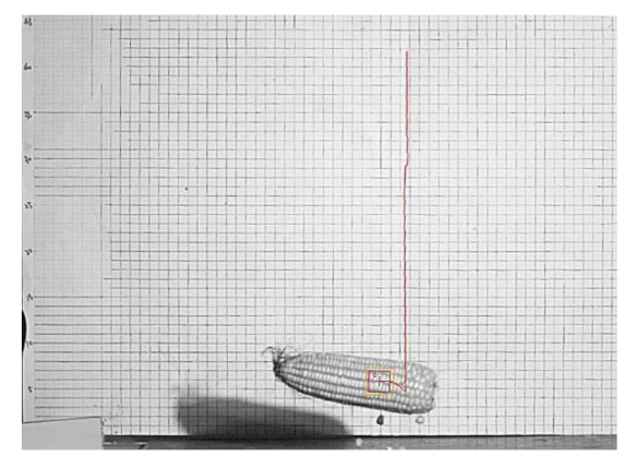
The drop test was important for testing the impact damage of the fruit. Previous studies have carried out the drop test to study the impact of the impact surface material type, drop height, drop direction and fruit maturity on the impact of fruit damage [27,28,29]. In order to determine the energy value required for ear deformation during ear snapping, a drop test was designed. The maize variety used in the drop test was Zhengdan 958, while the moisture content of the maize kernel was 30.41%. A high-speed camera was used to photograph the collision between the ears and ear snapping plate, as shown in Figure 2.
Due to the differences in plant physical properties, the growth position and angle of the ears were random. In order to simulate the contact between the plant and ear snapping plate, the inclination angles of the ears when the ears fell were set to 90°, 60°, and 30°, and 30 ears were taken from each angle for testing.
The ear was placed at a certain height, and the critical points at which the kernels were cracked, dropped, and other damages were obtained after conducting the repeated tests. The height h1, speed vc, angular velocity ω as well as other information pertaining to the ears after the collision with the steel plate were obtained by a high-speed camera, after which the mechanical energy before and after the collision was calculated. The mechanical energy E1 of the ear before the collision was the gravitational potential energy, and the mechanical energy E2 of the ear after the collision was the sum of the gravitational potential energy and kinetic energy of the ear after it bounced. Among them, the kinetic energy of the ear after collision was treated as the kinetic energy of a rigid body in plane motion. Then, the difference in the mechanical energy ΔE of the ear before and after the collision when the ear was damaged was calculated.
where, H1 was the height of the center of gravity of the ear before collision, mm; h1 was the height of the center of gravity of the ear after collision, mm; vc was the speed of the center of gravity of the ear after collision, m·s−1; JC was the moment of inertia of the ear, kg·m2; ω was the angular velocity of the center of gravity of the ear after collision, rad·s−1.
The trajectory of the center of gravity of the ear before and after collision was shown in Figure 3.
Afterward, the energy loss such as heat energy during the collision was ignored, for which the difference was the ear deformation energy. The test result was shown in Table 1.
Here, when the ears fell perpendicular to the ordinary steel plate, the energy for the damage and deformation of the ears was larger, with an average value of 0.842 J. When the ears were dropped at an inclination angle of 30°, the energy for the damage and deformation of the ears was smaller, with an average value of 0.791 J. In light of the above data, when the ears fell at an oblique angle of 30°, a minimum value Efn for ear damage and deformation was present. In order to reduce ear damage during ear picking, the minimum ear deformation energy Efn was taken as 0.424 J.
2.2.2. Improved Design of Ear Snapping Mechanism Based on Energy Conversion
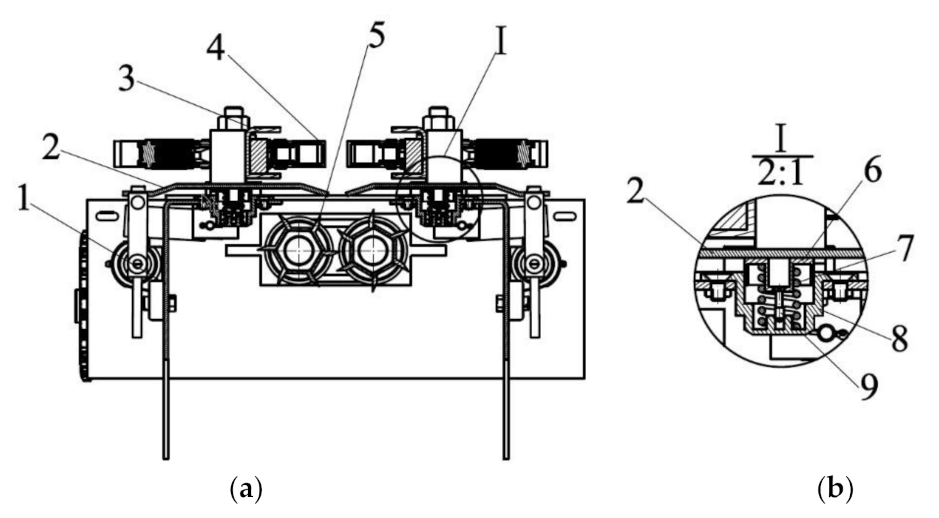
In order to reduce ear damage while picking ears, a method to transform ear deformation energy into other forms of energy was herein proposed. The kinetic energy lost during the collision process was converted into elastic potential energy of the compression spring, and the structure of the ear snapping mechanism was improved, as shown in Figure 4.
A damping unit was located under the snapping plate. The structure of the damping unit was shown in Figure 4b, which was mainly composed of a compression spring, top cover, bottom cover, and limit bolt. The bottom cover was fixed onto the frame via countersunk bolts, and a compression spring was installed inside the bottom cover. The top cover was located above the compression spring and was able to slide up and down with the expansion and contraction of the compression spring in the inner cavity of the bottom cover. The limit bolt was then connected with the threaded hole in the bottom cover by passing through the hole in the top cover.
The compression spring served as the core component of the low-damage ear snapping mechanism. Specifically, the design of the compression spring had a great influence on the reduction effect of ear damage. The design of the compression spring should satisfy the conditions in which the reduced kinetic energy of the ears during ear detaching process was partially converted into elastic potential energy of the compression spring. That was, after the mechanism was improved, Equation (7) would be
where, Ef′ was the deformation energy of the ear surface after the compression spring was added, J; Eep was the elastic potential energy stored by the compression spring, J; Epp was the position potential energy of the ear snapping plate, J.
The bounce of the ears should be avoided after being detached from the stalks in order to reduce the collision of the ears with the other parts. Thus, the kinetic energy of the ear should be converted into the elastic potential energy of the spring as well as the position potential energy of the ear snapping plate as much as possible. Therefore:
that was
where
T0 = Ef′ + E0 + Eep − Epp
Ef′ = T0 − E0 − Eep + Epp
In order to minimize ear damage during ear picking, Ef′ should be smaller than ear deformation energy Efn in order for part of the deformation energy Ef of the original mechanism to be replaced by elastic potential energy Eep:
where, m is the mass of the ear, the average ear mass tested in earlier test is 349 g; the rotational speed of stalk roller n is taken as 850 r/min; the radius of the stalk roller r is taken as 47.5 mm; the forward speed u2 is taken as 1.1 m/s; μ is the friction coefficient between the ears with the snapping plate, the value of μ is taken as 0.5 by test; θ is the angle between the bent section and the un-bended section of the snapping plate, it is taken as 18°; s is the length of the bent section of the snapping plate, mm; k is the stiffness coefficient of the compression spring, N/mm; l is the compression length of the compression spring, it is taken as 10 mm; mz is the mass of the snapping plate, it is taken as 2.88 kg.
Ef′ < Efn
Take the above parameters into Equations (14)–(16), k > 17.3 N/mm can be obtained.
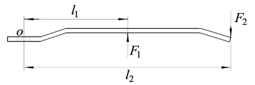
In addition, the stiffness of the compression spring should be sufficient in order to ensure that the impact force between the ear and ear snapping plate was able to push the compression spring without damaging the ear. Accordingly, the force analysis of the ear snapping plate was shown in Figure 5.
The torque of the ear snapping plate to the hinge point O should be balanced during the working process, so that:
where, l1 was the distance between the buffering point of the compression spring and the hinge point, which was taken as 110 mm; l2 was the distance between the impact point of the ear and the hinge point, which was taken as 218 mm; F2 was the impact force between the ear and the unilateral snapping plate. According to the results of the previous experiments, the range of force required for ear removal was [245 N, 809 N], while the maximum force required for ear removal was 809 N, so F2max was 404.5 N.
F1l1 = F2l2
Taking the above parameters into Equation (17), the maximum working load required by the spring was F1max = 801.6 N. The minimum force required for ear picking was 245 N, and the minimum working load required by the spring was F1min = 242.8 N. Taking F1max, F1min into Equation (18):
The maximum stiffness coefficient was taken as kmax = 55.8 N·mm−1. According to the theoretical analysis and calculation, the interval of stiffness coefficient of the compression spring that could realize energy conversion was determined to be (17.3 N·mm−1, 55.8 N·mm−1). The better value of the stiffness coefficient of the spring was then ascertained through a performance test.
2.3. Basic Structure of the Improved Mechanism
The low-damage ear snapping mechanism was mainly composed of a damping unit, snapping plate gap adjustment device, snapping plate, stalk roller, feeding chain and other components, as shown in Figure 6. A damping unit was installed under the snapping plate, and the lower shell of the damping unit was fixed to the frame by bolts with a compression spring mounted inside. The compression spring produced elastic deformation during snapping, thereby cushioning the impact between the ears and snapping plate.
When working, the plants moved to the ear snapping mechanism under the support of the feeding chain, while the helical lead-in section of the stalk roller grabbed and transported the plants backward. Meanwhile, the plants moved down quickly under the pull of the stalk roller. As the stalk was pulled down, when the ear with a higher moving speed touched the ear snapping plate, the contact and collision force between the ear and the snapping plate was reduced due to the buffering effect of the damping unit.
2.4. The Establishment of Simulation Model Based on Finite Element Method
In order to analyze the effect of the vibration reduction unit in reducing the damage of the ears, the impact process between the ear and improved snapping mechanism was simulated using the ABAQUS software (ABAQUS CAE 2017, Dassault Systèmes, Vélizy-Villacoublay CEDEX, France). As the components other than the ear snapping plate and compression spring had little effect on the energy change of the ear, the model was simplified, while the ear, ear snapping plate and compression spring were retained [30]. The adopted simulation parameters [9,31,32,33] were shown in Table 2.
The snapping plate, kernels, and cob were then modeled, after which an assembly of ear kernels and cob were built in Solidworks. Afterward, the files were saved in “.sat” format and imported into ABAQUS as a part. The snapping plate was defined as a three-dimensional discrete rigid body so as to simplify the analysis for the deformation of the snapping plate being very small compared to the kernel.
Material was given to each part, and a binding constraint between the kernel and cob was added. The mass points with extremely small masses and moments of inertia bounding with the corresponding plane were assembled on the rotation axis of the snapping plate and the hinge point of the spring, which was convenient in constraining the freedom of the plate and creating a spring element in ABAQUS. The contact model of the ear and the snapping plate was shown in Figure 7.
In order to clarify the damage reducing effect of the damping unit, a comparative test was carried out between the fixation of the snapping plate and the snapping plate with the damping unit. The better trail level of the rotational speed of the stalk roller and forward speed in the preliminary experiment were selected in the simulation test. The rotational speed of the stalk roller was 850 r·min−1, while the forward speed was 1.19 m·s−1, which were taken as the predefined field conditions assigned to the simulation model. The ears were initially perpendicular to the upper surface of the snapping plate.
The tensile force of 500 N, which varied according to the corresponding amplitude conditions, was applied, and the simulation time was 0.007 s. The internal energy of the kernel with the greatest stress, the internal energy and the kinetic energy of the ear were taken as process output items in order to analyze the role of the damping unit in energy reducing the ear damage.
2.5. Performance Test
2.5.1. Test Materials and Equipment
The type of maize plants used in the experiment was Longping 405, and the test material was collected on 1 October 2019. The maize plants that were cut from the top to the internode up the root were taken as the test sample. The stalks were required to be straight with the ears not drooped. The grain moisture content of the test sample was 33.40%.
The test was carried out on a self-made test rig, as shown in Figure 8. A self-made clamp was used to fix the plants, and the clamp was connected to the plant feeding mechanism via bolts. The stalk roller was driven by a YVF132S-4 variable-frequency adjustable-speed motor with a power of 5.5 kW. The feeding chain was driven by a YVF2-132S-6 variable-frequency adjustable-speed motor with a power of 3 kW. The plant feeding mechanism was driven by a YVF2-90L-4 variable-frequency adjustable-speed motor with a power of 1.5 kW, and a WPDO100-10-A screw reducer drove the plant feeding chain. The rotational speed of the stalk roller, speed of the feeding chain and speed of the plant feeding mechanism were adjusted through the frequency converter.
Prior to conducting the test, the plants were fixed on a clamp. Then, both the 5.5 kW motor and 3 kW motor were started, while the stalk roller and feeding chain moved. When the velocity of the stalk roller and the velocity of feeding chain were stabilized, the 1.5 kW motor was started, and the plants were fed into the low-damage snapping mechanism using the feeding mechanism.
2.5.2. Test Method
In order to determine the better working parameters of the low-damage ear snapping mechanism, the rotational speed of the stalk roller, forward speed and spring stiffness of the compression spring, which had a greater influence on the damage of the ears, were selected as the influencing factors of the performance test. According to the results of the previous single factor test, the range of the rotational speed of the stalk roller was determined to be 750–950 r·min−1, while the range of the forward speed was 1.1–1.7 m·s−1 and the range of the spring stiffness was 17.3–55.8 N·mm−1. In order to obtain the best parameters of the three factors, the Box–Behnken test was adopted in this study [34]. The test results were analyzed via ANOVA (analysis of variance) to determine the significance of the three factors. Design Expert(Version 8.0.6, Stat-Ease, Minneapolis, MN, USA) was used to optimize the parameters of the mechanism. The test factors and levels were shown in Table 3.
According to “China National Standard GB/T 21961-2008 Test Methods for Maize Harvesting Machinery”, 30 plants were collected for statistical analysis in each group of the experiments, and the test was repeated in triplicate. Furthermore, the performance evaluation index was ear damage rate S.
where, WL was the mass of kernels with obvious cracks and fallen kernels, g; WZ was the total mass of kernels, g.
3. Results and Discussion
3.1. Energy Conversion Analysis Based on FEM
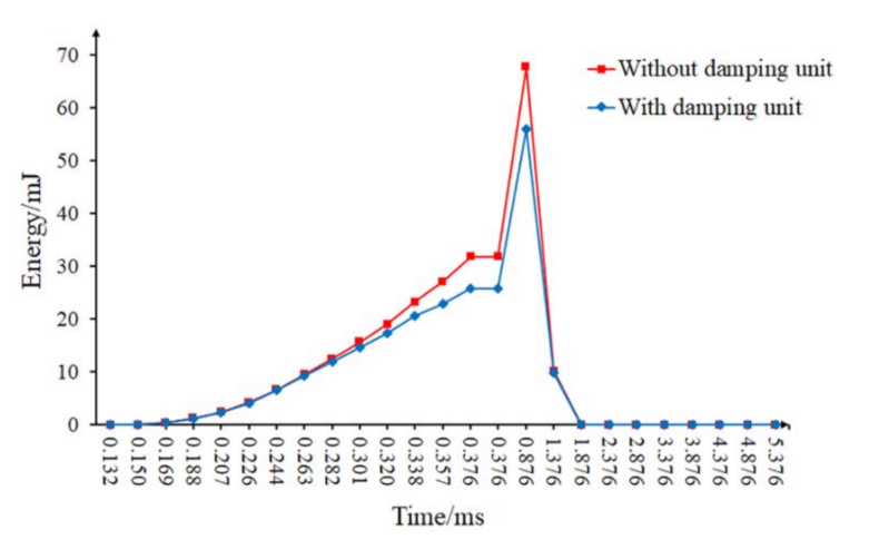
After ABAQUS software simulation and data processing, the internal energy change of a single kernel was shown in Figure 9, and the ear energy change was shown in Figure 10.
According to Figure 9, the internal energy of the kernel with the greatest force initially increased, after which it decreased with collision time. The peak value of internal energy was 72.74 mJ when the damping unit was not added, and the snapping plate was fixed. After adding the damping unit, the peak internal energy was 59.95 mJ. In addition, the peak internal energy was reduced by 17.58% compared to the mechanism without the damping unit. The corresponding results demonstrated that the internal energy decreased significantly for the kernel with the greatest stress after adding the damping unit to the ear snapping mechanism.
During the collision process, the change of ear energy when the ear snapping mechanism was not equipped with a damping unit was shown by the red curve in Figure 10.
Evidently, the ear kinetic energy started from 2000 mJ at 0 ms, which was followed by a steady rise to approximately 3043.61 mJ at 0.376 ms, in which the position potential energy of the ear was converted into kinetic energy. However, from then on, the ear kinetic energy sharply declined to 625.39 mJ at 0.726 ms. Since the collision was completed in an instant, the ear deformation reached maximum. At this time, the ear kinetic energy was converted into internal energy, and the ear kinetic energy dropped sharply. After that, the ear kinetic energy was on a steady rise to 1.776 ms, which then was kept stable. As the deformed ear part recovered, part of the internal energy of the ear was converted into kinetic energy; hence, the ear kinetic energy increased and then stabilized.
Moreover, the ear internal energy started from 0 mJ at 0 ms, which was followed by a steady rise to 471.27 mJ at 0.376 ms as the ear deformation was small at the initial moment. However, from then on, the ear internal energy rose sharply to 2875.84 mJ at 0.726 ms. Since the collision was completed in a very short time, the ear deformation reached maximum, and the ear internal energy reached maximum at this time. Afterward, the ear internal energy was on a steady drop to 1.776 ms as the deformed part of the ear recovered and part of the ear internal energy converted into kinetic energy, which then stabilized.
During the collision process, the change of ear energy when the ear snapping mechanism was equipped with a damping unit was shown by the blue curve in Figure 10.
As shown, the ear kinetic energy started from 2000 mJ at 0 ms, which was followed by a steady decrease to approximately at 1779.23 mJ at 0.376 ms as the ear kinetic energy partially converted into elastic potential energy of the damping unit. The ear kinetic energy then declined sharply to 335.99 mJ at 0.876 ms. Since the collision was completed in an instant, the ear deformation reached the maximum. At this time, the ear kinetic energy was converted into internal energy, and the ear kinetic energy dropped sharply. After that, the ear kinetic energy was on a steady rise until 1.876 ms, and then kept stabilizes. As the deformed ear part recovered, part of the internal energy of the ear was converted into kinetic energy; hence, the ear kinetic energy increased and then stabilized.
Additionally, the ear internal energy started from 0 mJ at 0 ms, which was followed by a steady rise to 347.26 mJ at 0.376 ms as the ear deformation was small at the initial moment. However, from then on, the ear internal energy rose sharply to the top of 1651.91 mJ at 0.876 ms. Since the collision was completed in a very short time, the ear deformation reached maximum, and the ear internal energy reached maximum at this time. Afterward, the ear internal energy was on a steady decline to 1.876 ms as the deformed part of the ear recovered and part of the ear inner energy converted into kinetic energy, which then stabilized.
In terms of the ears, the peak value of the ear internal energy was 2875.84 mJ without the damping unit, while the peak value of the ear internal energy was 1651.91 mJ after adding the damping unit. The peak internal energy was noted to be reduced by 42.56%, while the overall ear internal energy with damping unit decreased significantly. The peak value of the ear kinetic energy during collision was found to be 3043.61 mJ without the damping unit, while the peak value of the ear kinetic energy was 1779.23 mJ after adding the damping unit. The peak kinetic energy was reduced by 41.54%, demonstrating that after adding the damping unit, the ear kinetic energy reduced significantly. According to the above analysis, the internal energy of the kernel with the greatest force as well as the internal energy of the ear decreased significantly after adding the damping unit to the ear snapping mechanism, thereby reducing the possibility of causing ear damage.
3.2. Results and Discussion of Performance Test
3.2.1. Test Results
The test scheme and results were shown in Table 4, in which X1, X2, and X3 represented the coding value of each factor.
3.2.2. Regression Equation and Significance Test
The data processing software Design Expert 8.0.6 was used to perform multiple regressions fitting the test data, in which the regression equation of each factor with ear damage rate was obtained:
The results of the variance analysis for the regression equation were shown in Table 5. The fitting degree of the regression model of ear damage rate was found to be extremely significant (p < 0.01), while the p value of the lack-fit item was 0.9186, which was not significant, indicating a good fit with the actual test.
In regard to the regression equation of the ear damage rate, the p values of X1X2, X1X3, and X2X3 were all found to be greater than 0.05. Hence, the effect of these factors was not noted to be significant, whereas the effect of the other factors was significant. According to the regression coefficient test of Equation (20), the primary and secondary order of the factors affecting the ear damage rate was concluded to be the rotational speed of the stalk roller, spring stiffness and forward speed.
3.2.3. Analysis of the Influence of Interaction Factors on the Ear Damage Rate
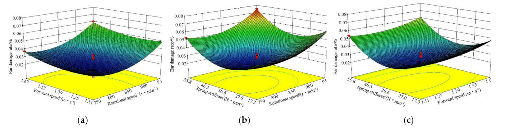
According to the established regression model of ear damage rate, one of the test factors was placed at the zero level, while the influence of the other two factors on the test index was considered. The corresponding surface map was then drawn, as shown in Figure 11.
When the spring stiffness was at the centre level, a response surface diagram of the rotational speed of the stalk roller and the forward speed on the ear damage rate was shown made, as shown in Figure 11a. When the rotational speed of the stalk roller was set at a certain level, since the forward speed increased, the partial velocity of the ear along the forward speed direction increased before collision, and the ear damage increased. When the forward speed was set at a certain level, since the rotational speed of the stalk roller increased, the partial velocity in the normal direction of the ear snapping plate increased before collision, and the ear damage increased. When the rotational speed of the stalk roller was 750~850 r·min−1 and the forward speed was 1.11~1.53 m·s−1, the ear damage rate was observed to be low.
When the forward speed was at the centre level, a response surface diagram of the rotational speed of the stalk roller and the spring stiffness on the ear damage rate was created, as shown in Figure 11b. When the rotational speed of the stalk roller was set at a certain level, the ear damage rate initially decreased, which then rose while the value of spring stiffness increased. When the value of the spring stiffness was small, the impact force on some ears was big. Moreover, some kinetic energy could not be converted into elastic potential energy, hence, the ear damage rate was high. With a rise in spring stiffness, the kinetic energy of the ear was transformed into elastic potential energy of the spring, and the damage of the ear was noted to be reduced. As the spring stiffness further increased, for some ears, the spring failed to produce compression effect due to the small impact force during the picking process, and the ear damage increased. When the spring stiffness was set at a certain level, as the rotation speed of the stalk roller increased, the ear damage rate gradually increased. Correspondingly, when the rotational speed of the stalk roller was 750~850 r·min−1 and the spring stiffness was 27.0~46.3 N·mm−1, the ear damage rate was observed to be low.
When the rotational speed of the stalk roller was at the center level, a response surface diagram of the forward speed and spring stiffness on the ear damage rate was made, as shown in Figure 11c. When the forward speed was set at a certain level, the ear damage rate initially decreased, which then increased as the value of spring stiffness increased. When the spring stiffness was set at a certain level, as the forward speed increased, the ear damage rate gradually increased. When the forward speed was 1.11~1.53 m·s−1 and the spring stiffness was 27.0~46.3 N·mm−1, the ear damage rate was noted to be low.
3.2.4. Parameter Optimization
In order to improve the performance of the low-damage snapping mechanism in reducing ear damage, the working parameters were optimized by Design-Expert. The constraint conditions were set as:
After optimization, the optimal values of each factor were obtained such that the rotational speed of the stalk roller was 805 r·min−1, forward speed was 1.29 m·s−1, and spring stiffness was 33.5 N·mm−1. In addition, the ear damage rate predicted by the model was 0.023%.
The verification test was conducted under the conditions such that the rotational speed of the roller was 805 r·min−1, forward speed was 1.29 m·s−1, and spring stiffness was 33.5 N·mm−1. The test results are shown in Table 6. The ear damage rate of the optimized ear snapping mechanism was found to be 0.019%, which was less than 0.023% as predicted by the model.
4. Conclusions
- Ear picking served as a key link in maize harvesting and reducing stresses on the ear, which was important in solving issues related to ear damage. However, stresses of the ears were noted to be more complicated during the picking process. Therefore, this study analysed the interaction between the ears and the ear picking parts in view of energy balance. By conducting a theoretical analysis, the main factors of ear damage were found to be the machine forward speed and speed of the stalk roller.
- In order to reduce the ear damage in the ear picking process, the ear snapping mechanism was improved based on ear deformation energy conversion. Accordingly, the compression spring was designed, and the working range of the compression spring was determined (17.3 N·mm−1, 55.8 N·mm−1). In order to verify the effectiveness of the ear deformation energy reduction of the low-damage mechanism, a comparative experiment was carried out in FEM under the conditions of the snapping plate with or without compression spring. The results showed that the ear snapping plate with a compression spring could reduce the internal energy of both the most stressed kernel and the whole ear. In addition, the possibility of ear damage was reduced at the same time.
- In order to determine the optimized parameters of the snapping mechanism, a performance test was carried out based on the Box–Behnken test design. The primary and secondary order for which the factors affecting the ear damage rate was found to be the rotational speed of the stalk roller, spring stiffness and forward speed. The data processing software Design Expert 8.0.6 was used to optimize the parameters. The ear damage rate was taken as the test index, in which the rotational speed of the stalk roller was found to be 805 r·min−1, while the forward speed was 1.29 m·s−1 and the spring stiffness was 33.5 N·mm−1. Furthermore, the ear damage rate predicted by the model was noted to be 0.023%.
Author Contributions
Conceptualization, Z.Z.; methodology, Z.Z.; software, Z.Z.; validation, Z.Z.; writing—original draft preparation, Z.Z.; writing—review and editing, A.G.; funding acquisition, A.G. All authors have read and agreed to the published version of the manuscript.
Funding
This work was sponsored by the Shandong Provincial Key Science and Technology Innovation Engineering Project (2018CXGC0217), the Shandong Provincial Natural Science Foundation (ZR2017BEE032) and the 13th Five-Year National Key Research and Development Program (2018YFD0300606).
Institutional Review Board Statement
Not applicable.
Informed Consent Statement
Not applicable.
Data Availability Statement
Not applicable.
Acknowledgments
We wish to thank the support of the above foundations.
Conflicts of Interest
The authors declare no conflict of interest.
References
- Ren, B.; Li, X.; Dong, S.; Liu, P.; Zhao, B.; Zhang, J. Soil physical properties and maize root growth under different tillage systems in the North China Plain. Crop J. 2018, 6, 669–676. [Google Scholar] [CrossRef]
- Cui, T.; Fan, C.; Zhang, D.; Yang, L.; Li, Y.; Zhao, H. Research progress of maize mechanized harvesting technology. Trans. Chin. Soc. Agric. Mach. 2019, 50, 1–13. [Google Scholar]
- Wang, K.R.; Xie, R.Z.; Ming, B.; Hou, P.; Xue, J.; Li, S.K. Review of combine harvester losses for maize and influencing factors. Int. J. Agric. Biol. Eng. 2021, 14, 1–10. [Google Scholar] [CrossRef]
- Hanna, H.M.; Kohl, K.D.; Haden, D.A. Machine losses from conventional versus narrow row corn harvest. Appl. Eng. Agric. 2002, 18, 405–409. [Google Scholar] [CrossRef]
- Paulsen, M.R.; de Assis de Carvalho Pinto, F.; de Sena, D.G., Jr.; Zandonadi, R.S.; Ruffato, S.; Gomide Costa, A.; Ragagnin, V.A.; Danao, M.-G.C. Measurement of Combine Losses for Corn and Soybeans in Brazil. Appl. Eng. Agric. 2013, 30, 841–855. [Google Scholar]
- Yang, L.; Cui, T.; Qu, Z.; Li, K.; Han, D.; Yan, B.; Zhao, D.; Zhang, D. Development and application of mechanized maize harvesters. Int. J. Agric. Biol. Eng. 2016, 9, 15–28. [Google Scholar]
- Fu, Q.; Fu, J.; Chen, Z.; Han, L.; Ren, L. Effect of impact parameters and moisture content on kernel loss during corn snapping. Int. Agrophys. 2019, 33, 493–502. [Google Scholar] [CrossRef]
- Zhang, Z.; Chi, R.J.; Du, Y.F.; Pan, X.; Xie, B. Experiments and modeling of mechanism analysis of maize picking loss. Int. J. Agric. Biol. Eng. 2021, 14, 11–19. [Google Scholar] [CrossRef]
- Qin, J.; Yin, Y.; Liu, Z.; Du, Y.; Wang, G.; Zhu, Z.; Li, Z. Optimisation of maize picking mechanism by simulation analysis and high-speed video experiments. Biosyst. Eng. 2020, 189, 84–98. [Google Scholar] [CrossRef]
- Chen, Z.; Wassgren, C.; Ambrose, K. A review of grain kernel damage: Mechanisms, modeling, and testing procedures. Trans. ASABE 2020, 63, 455–475. [Google Scholar] [CrossRef]
- Xu, L.; Li, Y.; Ma, Z.; Zhao, Z.; Wang, C. Theoretical analysis and finite element simulation of a rice kernel obliquely impacted by a threshing tooth. Biosyst. Eng. 2013, 114, 146–156. [Google Scholar]
- Yang, F.; Du, Y.; Fu, Q.; Li, X.; Li, Z.; Mao, E.; Zhu, Z. Design and testing of seed maize ear peeling roller based on hertz theory. Biosyst. Eng. 2021, 202, 165–178. [Google Scholar] [CrossRef]
- Gambella, F.; Dimauro, C.; Paschino, F. Evaluation of fruit damage caused by mechanical harvesting of table olives. Trans. ASABE 2013, 56, 1267–1272. [Google Scholar]
- Fu, H.; He, L.; Ma, S.; Karkee, M.; Chen, D.; Zhang, Q.; Wang, S. ‘Jazz’ apple impact bruise responses to different cushioning materials. Trans. ASABE 2017, 60, 327–336. [Google Scholar]
- Wang, W.; Lu, H.; Zhang, S.; Yang, Z. Damage caused by multiple impacts of litchi fruits during vibration harvesting. Comput. Electron. Agric. 2019, 162, 732–738. [Google Scholar] [CrossRef]
- Wang, W.; Zhang, S.; Fu, H.; Lu, H.; Yang, Z. Evaluation of litchi impact damage degree and damage susceptibility. Comput. Electron. Agric. 2020, 173, 105409. [Google Scholar] [CrossRef]
- Celik, H.K. Determination of bruise susceptibility of pears (Ankara variety) to impact load by means of FEM-based explicit dynamics simulation. Postharvest Biol. Technol. 2017, 128, 83–97. [Google Scholar] [CrossRef]
- Du, D.; Wang, B.; Wang, J.; Yao, F.; Hong, X. Prediction of bruise susceptibility of harvested kiwifruit (Actinidia chinensis) using finite element method. Postharvest Biol. Technol. 2019, 152, 36–44. [Google Scholar] [CrossRef]
- Kitthawee, U.; Pathaveerat, S.; Srirungruang, T.; Slaughter, D. Mechanical bruising of young coconut. Biosyst. Eng. 2011, 109, 211–219. [Google Scholar] [CrossRef]
- Berry, N.K.; Fielke, J.M.; Saunders, C. A Mastercurve to predict annual ryegrass (Lolium rigidum) seed devitalisation when exposed to multiple single sided impacts. Biosyst. Eng. 2015, 133, 56–63. [Google Scholar] [CrossRef]
- Bao, Y.; Yang, C.; Zhao, Y.; Liu, X.; Guo, Y. Collision injury assessment of mechanical harvesting blueberry fruit based on collision deformation energy. Trans. Chin. Soc. Agric. Eng. 2017, 33, 283–292. [Google Scholar]
- Huynh, V.M.; Powell, T.; Siddall, J.N. Threshing and separating process—A mathematical model. Trans. ASAE 1982, 25, 65–73. [Google Scholar] [CrossRef]
- Wang, X. Mechanical Properties of Rice Grain and Threshing Injury Based on the Energy Conservation. Master’s Thesis, Jiangsu University, Zhenjiang, China, 2007. [Google Scholar]
- Li, Y.; Wang, X.; Xu, L. Threshing injury to rice grain based on the energy conservation. Chin. J. Mech. Eng. 2007, 43, 160–164. [Google Scholar] [CrossRef]
- Fu, Q.; Fu, J.; Chen, Z.; Ren, L. Loss reduction mechanism and experiment on snapping of rigid-flexible coupling corn head. Trans. Chin. Soc. Agric. Mach. 2020, 51, 60–68. [Google Scholar]
- Li, K. Design and Experimental Study on Gap-Adjustable Combined Ear-Picking Mechanism of Corn. Ph.D. Thesis, China Agricultural University, Beijing, China, 2018. [Google Scholar]
- Yousefi, S.; Farsi, H.; Kheiralipour, K. Drop test of pear fruit: Experimental measurement and finite element modelling. Biosyst. Eng. 2016, 147, 17–25. [Google Scholar] [CrossRef]
- Caglayan, N.; Oral, O.; Celik, H.K.; Cinar, R.; Rodrigues, L.; Rennie, A.; Akinci, I. Determination of time dependent stress distribution on a potato tuber during drop case. J. Food Process Eng. 2018, 41, e12869. [Google Scholar] [CrossRef]
- Celik, H.K.; Ustun, H.; Erkan, M.; Rennie, A.; Akinci, I. Effects of bruising of ‘pink lady’ apple under impact loading in drop test on firmness, colour and gas exchange of fruit during long term storage. Postharvest Biol. Technol. 2021, 179, 111561. [Google Scholar] [CrossRef]
- Tai, J.; Li, H.; Guan, Y.; Ding, N.; Du, Y.; Mao, E. Simulation of a maize ear picking device with a longitudinal horizontal roller based on hypermesh modeling. BioResources. 2021, 16, 1394–1410. [Google Scholar] [CrossRef]
- Zhu, Z.; Yue, X.; Du, Y.; Song, Z.; Mao, E.; Wang, B. Dynamic simulation and high-speed photography experiment on corn-ear husking. Trans. Chin. Soc. Agric. Eng. 2015, 31, 42–48. [Google Scholar]
- Hou, M. Study on Mechanical Properties of Corn Kernel and Design of Threshing Test Bed. Master’s Thesis, Henan Agricultural University, Zhengzhou, China, 2017. [Google Scholar]
- Wang, B.; Wang, J.; Du, D. Finite element analysis of dynamic impact damage process of maize kernel based on HyperMesh and LS-DYNA. J. Zhejiang Univ. Agric. Life Sci. 2018, 44, 465–475. [Google Scholar]
- Pan, L.; Chen, J. Experiment Design and Data Processing; Southeast University Press: Nanjing, China, 2008; pp. 192–239. [Google Scholar]
Figure 1.
The collision between ear and snapping plate: x—x axis of the coordinate system; y—y axis of the coordinate system; w—the speed of the ear after the collision; wt—the component velocity of w in the x axis direction; wn—the component velocity of w in the y axis direction; β—the angle between w and wn; u—the speed of the ear before the collision; ut—the component velocity of u in the x axis direction; un—the component velocity of u in the y axis direction; α—the angle between u and un.

Figure 2.
Ear drop test. (1) High-speed camera; (2) light supplement lamp; (3) height marker; (4) steel plate.
Figure 2.
Ear drop test. (1) High-speed camera; (2) light supplement lamp; (3) height marker; (4) steel plate.

Figure 3.
The trajectory of the centre of gravity of the ear before and after collision.

Figure 4.
Sectional view of low-loss snapping mechanism: (a) Sectional view of the mechanism; (b) partial view of damping unit. (1) Frame; (2) snapping plate; (3) chain guard; (4) feeding chain; (5) stalk roller; (6) head cover; (7) compression spring; (8) bottom cover; (9) limit bolt.
Figure 4.
Sectional view of low-loss snapping mechanism: (a) Sectional view of the mechanism; (b) partial view of damping unit. (1) Frame; (2) snapping plate; (3) chain guard; (4) feeding chain; (5) stalk roller; (6) head cover; (7) compression spring; (8) bottom cover; (9) limit bolt.

Figure 5.
Force analysis of snapping plate.

Figure 6.
Structural figure of low-damage snapping mechanism. (1) Frame; (2) feeding chain; (3) stalk roller; (4) snapping plate; (5) chain guard; (6) gearbox; (7) snapping plate gap adjustment device; (8) damping unit.
Figure 6.
Structural figure of low-damage snapping mechanism. (1) Frame; (2) feeding chain; (3) stalk roller; (4) snapping plate; (5) chain guard; (6) gearbox; (7) snapping plate gap adjustment device; (8) damping unit.

Figure 7.
Contact model between ear and snapping plate. (1) Ear; (2) snapping plate.

Figure 8.
Test device. (1) Low-damage snapping mechanism; (2) rotational speed regulating motor of stalk roller; (3) speed regulating motor of feeding chain; (4) plant feeding mechanism; (5) corn plants.
Figure 8.
Test device. (1) Low-damage snapping mechanism; (2) rotational speed regulating motor of stalk roller; (3) speed regulating motor of feeding chain; (4) plant feeding mechanism; (5) corn plants.

Figure 9.
Internal energy change of single kernel.

Figure 10.
Ear energy change.

Figure 11.
Effects of various factors on ear damage rate: (a) y(X1,X2,0); (b) y(X1,0,X3); (c) (0,X2,X3).
Figure 11.
Effects of various factors on ear damage rate: (a) y(X1,X2,0); (b) y(X1,0,X3); (c) (0,X2,X3).


Table 1.
Ear deformation energy.
| Level | Range/J | Mean/J | Standard Deviation/J |
|---|---|---|---|
| 30° | 0.424~1.144 | 0.791 | 0.166 |
| 60° | 0.442~1.135 | 0.817 | 0.171 |
| 90° | 0.621~1.243 | 0.842 | 0.156 |
Table 2.
Simulation parameters settings.
| Item | Parameters | Values |
|---|---|---|
| Corn cob | Poisson’s ratio | 0.0539 |
| Elastic modulus/Pa | 5 × 10⁸ | |
| Density/(kg·m−3) | 0.6 × 10³ | |
| Corn kernel | Poisson’s ratio | 0.031 |
| Elastic modulus/Pa | 2.8 × 10⁸ | |
| Density/(kg·m−3) | 1.24 × 10³ | |
| Corn kernel-steel board | Coefficient of static friction | 0.34 |
Table 3.
Factors and levels of test.
| Levels | Factors | ||
|---|---|---|---|
| Rotational Speed x1/(r·min−1) | Forward Speed x2/(m·s−1) | Spring Stiffness x3/(N·mm−1) | |
| −1 | 750 | 1.11 | 17.3 |
| 0 | 850 | 1.39 | 36.6 |
| 1 | 950 | 1.67 | 55.8 |
Table 4.
Test results.
| Serial Number | Factors | Respond Values | ||
|---|---|---|---|---|
| Rotational Speed X1 | Forward Speed X2 | Spring Stiffness X3 | Ear Damage Rate/% | |
| 1 | −1.00 | −1.00 | 0.00 | 0.028 |
| 2 | 1.00 | −1.00 | 0.00 | 0.049 |
| 3 | −1.00 | 1.00 | 0.00 | 0.037 |
| 4 | 1.00 | 1.00 | 0.00 | 0.060 |
| 5 | −1.00 | 0.00 | −1.00 | 0.041 |
| 6 | 1.00 | 0.00 | −1.00 | 0.062 |
| 7 | −1.00 | 0.00 | 1.00 | 0.053 |
| 8 | 1.00 | 0.00 | 1.00 | 0.075 |
| 9 | 0.00 | −1.00 | −1.00 | 0.042 |
| 10 | 0.00 | 1.00 | −1.00 | 0.048 |
| 11 | 0.00 | −1.00 | 1.00 | 0.054 |
| 12 | 0.00 | 1.00 | 1.00 | 0.060 |
| 13 | 0.00 | 0.00 | 0.00 | 0.029 |
| 14 | 0.00 | 0.00 | 0.00 | 0.032 |
| 15 | 0.00 | 0.00 | 0.00 | 0.023 |
| 16 | 0.00 | 0.00 | 0.00 | 0.027 |
| 17 | 0.00 | 0.00 | 0.00 | 0.022 |
Table 5.
Variance analysis of regression equation.
| Source | Ear Damage Rate | |||
|---|---|---|---|---|
| Sum of Squares | Freedom | F Value | p Value | |
| Model | 3.84 × 10⁻³ | 9 | 38.57 | <0.0001 |
| X1 | 9.461 × 10⁻⁴ | 1 | 85.51 | <0.0001 |
| X2 | 1.280 × 10⁻⁴ | 1 | 11.57 | 0.0114 |
| X3 | 3.001 × 10⁻⁴ | 1 | 27.13 | 0.0012 |
| X1X2 | 1.000 × 10⁻⁶ | 1 | 0.09 | 0.7724 |
| X1X3 | 2.5 × 10⁻⁷ | 1 | 0.023 | 0.8848 |
| X2X3 | 0 | 1 | 0.00 | 1.0000 |
| X12 | 5.888 × 10⁻⁴ | 1 | 53.21 | 0.0002 |
| X22 | 1.084 × 10⁻⁴ | 1 | 9.80 | 0.0166 |
| X32 | 1.572 × 10⁻³ | 1 | 142.12 | <0.0001 |
| Residual | 7.745 × 10⁻⁵ | 7 | ||
| Lack-Fit | 8.250 × 10⁻⁶ | 3 | 0.16 | 0.9186 |
| Pure Error | 6.920 × 10⁻⁵ | 4 | ||
| Cor total | 3.918 × 10⁻³ | 16 | ||
Table 6.
Test results.
| Serial No. | Ear Damage Rate/% |
|---|---|
| 1 | 0.019 |
| 2 | 0.018 |
| 3 | 0.020 |
| 4 | 0.020 |
| 5 | 0.018 |
| Mean | 0.019 |
Publisher’s Note: MDPI stays neutral with regard to jurisdictional claims in published maps and institutional affiliations. |
© 2021 by the authors. Licensee MDPI, Basel, Switzerland. This article is an open access article distributed under the terms and conditions of the Creative Commons Attribution (CC BY) license (https://creativecommons.org/licenses/by/4.0/).
Share and Cite
MDPI and ACS Style
Zhang, Z.; Geng, A. Development and Evaluation of Low-Damage Maize Snapping Mechanism Based on Deformation Energy Conversion. Appl. Sci. 2021, 11, 12158. https://0-doi-org.brum.beds.ac.uk/10.3390/app112412158
AMA Style
Zhang Z, Geng A. Development and Evaluation of Low-Damage Maize Snapping Mechanism Based on Deformation Energy Conversion. Applied Sciences. 2021; 11(24):12158. https://0-doi-org.brum.beds.ac.uk/10.3390/app112412158
Chicago/Turabian StyleZhang, Zhilong, and Aijun Geng. 2021. "Development and Evaluation of Low-Damage Maize Snapping Mechanism Based on Deformation Energy Conversion" Applied Sciences 11, no. 24: 12158. https://0-doi-org.brum.beds.ac.uk/10.3390/app112412158
Note that from the first issue of 2016, this journal uses article numbers instead of page numbers. See further details here.