
A Typology Model of Temporary Facility Constraints for Automated Construction Site Layout Planning


1
Division of Architecture & Urban Design, Incheon National University, 119 Academy-ro, Yeonsu-gu, Incheon 22012, Korea
2
Department of Architecture, Sahmyook University, Seoul 01795, Korea
*
Author to whom correspondence should be addressed.
Appl. Sci. 2021, 11(3), 1027; https://0-doi-org.brum.beds.ac.uk/10.3390/app11031027
Submission received: 14 December 2020
/
Revised: 11 January 2021
/
Accepted: 20 January 2021
/
Published: 23 January 2021
(This article belongs to the Special Issue BIM and Its Integration with Emerging Technologies)
Abstract
:This study sought to develop a typology model of temporary facility constraints that can be used practically in construction site layout planning (CSLP) automation models. A triangulated methodology (literature review, in-depth interviews, and actual case studies) was used to identify constraints of 11 temporary facilities that are considered mainly in CSLP and to classify them into six constraint types (i.e., dimensional, regional, relocation, non-overlap, inter-facility distance, and visibility constraints) and seven subtypes. In addition, this study proposed computational modeling methods that would allow a computer to judge whether or not the constraints are met by a created construction site layout. This study contributes to CSLP theory by providing a typology model of temporary facilities that can be used in the model-based verification of the created construction site layout and constraint processing condition in CSLP optimization models. This would also help provide efficient, safe, and eco-friendly construction site management, while refraining from experience- and intuition-centered CSLP practices.
1. Introduction
Construction site layout planning (CSLP) is one of the important processes that should take place for construction management to be successfully carried out before the commencement of main work. It primarily involves determining the type, size, and number of temporary facilities (TFs) installed and used temporarily at the site during the construction period (e.g., gate, access road, lifts, site offices, storages, laydown areas, security offices, toilets, hazard storage areas, and work areas) and identifying the relative locations between the facilities to support the efficient function of the site. Effective construction site layout contributes to minimizing travel distances, site congestion, time, and efforts required for material handling and transportation, and operational costs [1,2,3], and this, in turn, has a positive effect on the safety, sustainability, scheduling, and cost management of the construction site [4,5,6,7].
Despite such importance, CSLP still relies on experience, intuition, and previous construction site layout data. It is thus carried out manually in many construction projects today. However, this approach leads to difficulties in selecting appropriate temporary facilities and laying them out because the relationship between multiple temporary facilities included in a construction site layout is complex. There are also many limitations to be considered when installing them, and it is difficult to gauge the impact of construction site layout on construction labor and operation [8]. In addition, there may be variations in the quality of construction site layout as the planners’ ability to collect data varies depending on the influence they have within the company. Therefore, CSLP is one of the most difficult tasks in site planning that requires human interpretation of the parameters and characteristics of the construction project and is thus a problem related to the optimization of the construction site layout performance [9,10].
To address this problem, studies on developing automated CSLP models using some optimization algorithms have begun to take place. Nevertheless, there are very few cases where these models are used in practice. One of the reasons is the insufficient application of constraints (i.e., the rules defined to achieve the layout goal of finding the location of temporary facilities on the site while meeting a set of constraints [11]) in CSLP, which leads to impractical construction site layouts [12]. In other words, constraints should be appropriately defined and checked to allow computer models to solve design problems [8]. However, the existing CSLP automation models do not take into account the constraints as thoroughly as construction site layout planners consider them when creating actual construction site layouts [13]. For example, a boundary constraint that temporary facilities should be laid out inside the site boundary, and an overlapping constraint that objects should not overlap are used by many construction site layout optimization models; however, constraints that deal with environmental and safety problems, such as noise and falling objects [14], and constraints considering geometric relationships, like maintaining a safe distance between site objects such as neighboring buildings and site elements, are rarely applied [15]. However, no attempts have been made to develop a constraint model for use in CSLP automation models through a systematic investigation of the constraints of temporary facilities applied in actual cases.
1.1. Objective
To solve the aforementioned problems, this study attempts to investigate the layout constraints of each temporary facility that can be used in CSLP automation models and develop a typology model of temporary facility constraints. The typology model can later be combined with a CSLP automation model using a computer, thereby contributing to creating a realistic, efficient, safe, easily accessible, and eco-friendly construction site layout. In general, inappropriate constraint settings can pose modeling problems that under-specify the layout problems, resulting in too many solutions, or over-specify the layout problems, causing too few possible solutions, both of which lead to poor-quality output [16]. To minimize such problems, each constraint that is investigated and categorized in the typology model must achieve the following characteristics.
Clarity: Transcription of rules in a natural language such that they can be applied to algorithms is one of the most difficult tasks in implementing automated rule checking [15], and the vagueness and ambiguity of the natural language make it difficult to interpret and translate the rules [17]. Therefore, in order for the constraints in a natural language to be easily transcribed in a computer-interpretable form, the meaning of the identified constraints should be clearly conveyed to anyone.
Substantiality: Constraints should be considered not only in theory but also in the CSLP practice by construction site layout planners. Thus, a constraint should appear in actual CSLP cases, not only in one specific project but also in multiple projects observed by the authors.
Comprehensiveness: The typology model of constraints should include all constraints that are required for the layout of temporary facilities. Thus, there must not be a constraint that is substantial enough to appear in actual CSLP cases but is missed in the developed typology model.
1.2. Scope
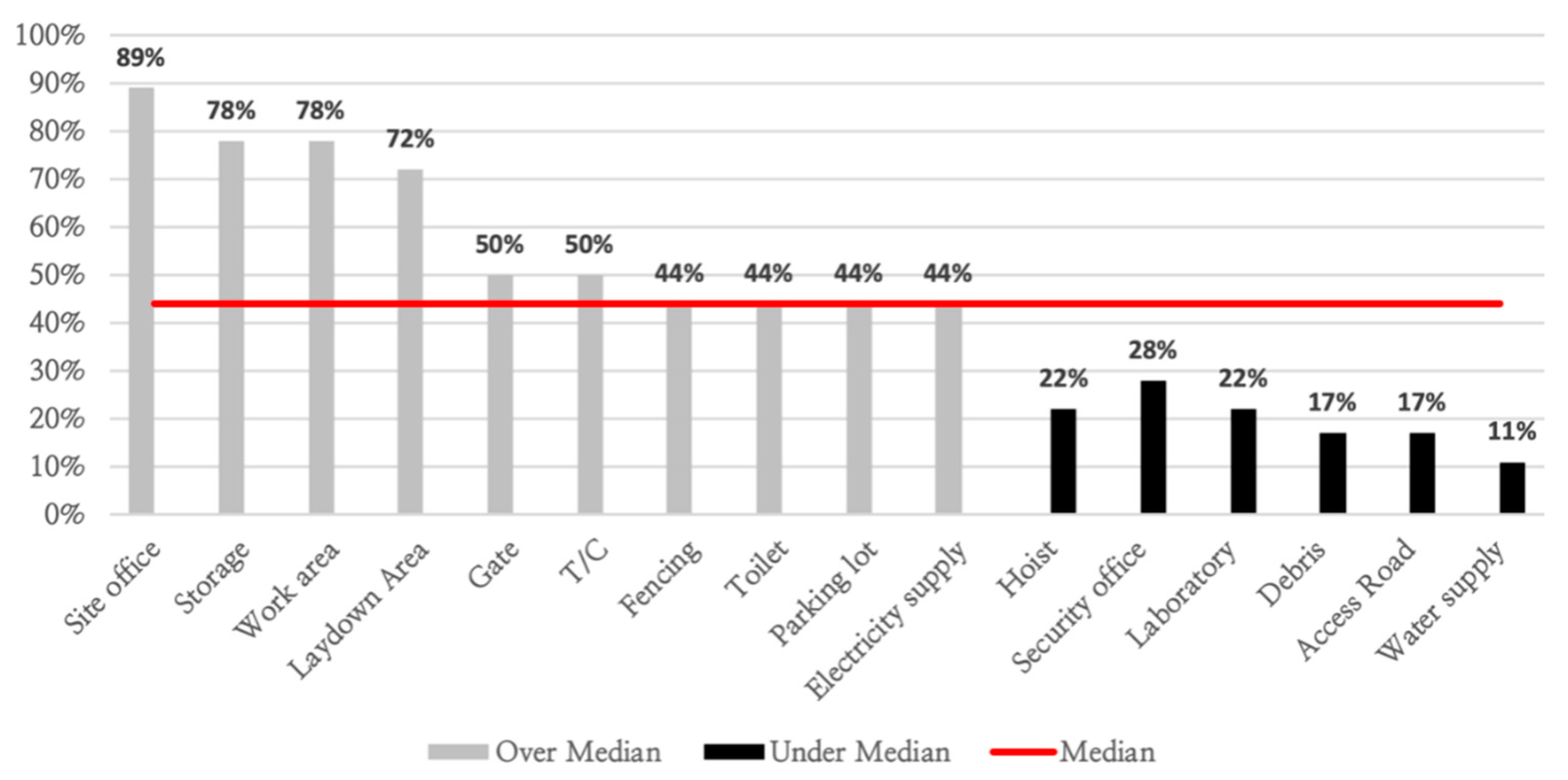
To identify the most frequently used temporary facilities as layout items in CSLP and to build a model of constraints for them, 18 CSLP cases for 12 building types were collected through a literature review of research papers published from 1995 to 2019 [6,7,8,18,19,20,21,22,23,24,25,26,27,28,29,30,31,32]. All temporary facilities laid out in these cases were then identified to select ten temporary facilities that are frequently shown (equal to or greater than the median value (44%)) (Figure 1). Although the access road did not meet the criterion of frequency, it was included in the research scope because of its importance. To put it concretely, it has a significant impact on the movement of labor, equipment, and materials on site and, thus, should be considered important in optimizing the location of temporary facilities [2]. As an example, some recent studies [31,33,34] used access roads as an important factor in the evaluation of construction site layout and constraints for layout optimization. Accordingly, the following 11 temporary were are selected and included in the scope of this study: site office, storage, work area (e.g., workshop and fabrication yard), laydown area, gate (for vehicles), tower crane (T/C), fencing, toilet, parking lot, electricity supply, and access road.
2. Literature Review
CSLP automation models commonly apply boundary constraints to ensure that all temporary facilities are located within the site and the non-overlapping constraint to prevent the objects from overlapping. However, in these models, constraints are considered differently and perceived in a limited manner (Table 1). For example, Mawdesley et al. [6], who attempted to solve the construction site layout problem through a genetic algorithm with the cost of transportation or removal as a layout evaluation value, used constraints to limit the placement of material storage in hazardous areas and to prevent noise-producing work areas from being placed close to the office. Easa and Hossain [35], who proposed a mathematical optimization-based model used constraints to make some temporary facilities be placed adjacent to each other or separated from each other and to make some objects be seen at specific locations on the site. Kumar and Cheng [36] who proposed an automated framework to create a dynamic site layout model by utilizing Building Information Model (BIM) used constraints to ensure that specific temporary facilities are within the radius of a tower crane and to maintain a buffer distance between the pathways and temporary facilities used commonly by trucks and machines for smooth site operation and labor safety. Razavialavi and Abourizk [31], who proposed a framework using heuristic optimization through a genetic algorithm, used constraints related to the size of temporary facilities to be placed. Meanwhile, there was also a case of developing an integrated framework and model for minimizing construction site risk using only boundary and non-overlapping constraints [37].
Such insufficient applications of constraints in CSLP may lead not only to an inefficient travel path during construction, but also to an increase in costs incurred from the installation and relocation of temporary facilities, and ultimately have a negative impact on the construction site layout optimization [38]. Therefore, it is necessary to identify and apply various constraints that can be derived from historical data such as past similar projects [14,37]. Additionally, some research [39,40] has noted that in the case of a construction project that has multiple phases, the task of entering repeated data (i.e., constraints) for each phase can be tedious. Nevertheless, in relation to the existing CSLP automation models, there has not been a constraint model that could be comprehensively used to create a practical construction site layout [24]. In addition, although constraints in construction site layout are heuristic factors that should be used by combining knowledge from experts or literature, there was a lack of efforts to find out the constraints that are actually applied to temporary facilities through a close examination of literature and expert knowledge. These limitations necessitate the development of a constraint typology model that identifies constraints comprehensively, classifies them into constraint types, and presents computational modeling methods for each of the constraint types that can be utilized in the layout of temporary facilities in CSLP.
In addition, the constraint types used in the existing CSLP models have different names despite being the same functions. For example, constraints that place temporary facilities on the site boundaries are called “region constraint” [35], “boundary constraint” [34,41], or “being inside the boundaries constraint” [31]. The constraint for laying out or not laying out temporary facilities in a specific region has been called the “object-region constraint” [35], “exclusion/inclusion-zone constraints” [41], or “available site space constraint” [36]. In addition, the constraint that determines the minimum or maximum distance between the two facilities in relation to the operation, safety, and security of the site is often referred to as “minimum and maximum distance constraints” [31,41], but also called “object adjacency constraint” or “facility proximity constraint” [35]. In this regard, the development of a temporary facility constraint typology model is important as it can provide common vocabularies for the identification and classification of CSLP constraints.

Table 1.
Some CSLP automation models and constraints applied in the models except boundary and overlap constraints.
Table 1.
Some CSLP automation models and constraints applied in the models except boundary and overlap constraints.
| Ref. | Automation Methods | Constraints Applied | Description |
|---|---|---|---|
| [6] | GA 1 | Exclusion of facilities Inter-facility distance | Limit the placement of material storage in environmentally sensitive areas Keep the noisy workshop away from the office and place the T/C close to the building |
| [27] | ABC 2 | Tower crane access | Ensure that temporary facilities such as the laydown area should be placed within the radius of T/C |
| [30] | GA | Proximity or remoteness of particular facilities | Keep fuel storage away from risk-sensitive areas and make sure that the site office is located relatively quiet and remote from the area where construction activity takes place |
| [31] | GA | Inclusion/exclusion area Min/max distance Distance Size Inclusion/exclusion | Place a given TF inside/outside the boundary of the area Limit the minimum/maximum distance between the points of TFs and other facilities Limit the minimum distance between T/C and TFs to avoid falling objects Limit the size of some TFs according to the characteristics of the site Limit the region where TFs are laid out depending on the favorable/unfavorable area |
| [34] | PSO 3 | Inter-facility distance | Maintain the distance between all pairs of TFs for safety or productivity reasons |
| [35] | BMILP 4 | Object Adjacency Object-Region Facility proximity Visibility | Make sure that the TFs and some objects are adjacent to each other Do not allow TFs to be located in a specific region depending on the site conditions Place TFs and some objects within the minimum distance of each other on the site Ensure that one or more objects are visible from a specific location on the construction site |
| [36] | GA | Safety Tower crane Site Accessibility | Maintain the minimum safety distance between TFs and other objects Place a specific material storage yard in the radius of T/C Make sure that all TFs keep a minimum distance of 1m from the path |
| [41] | ADPA 5 | Min/max distance Inclusion/exclusion zone | Provide a safe buffer distance around the building, or ensure that the distance between T/C and supply point does not exceed the reach distance of T/C Limit or allow the layout of TFs within a specific area |
1 genetic algorithm; 2 artificial bee colony; 3 particle swarm optimization; 4 binary-mixed-integer-linear programming; 5 approximate dynamic programming algorithm.
3. Methods
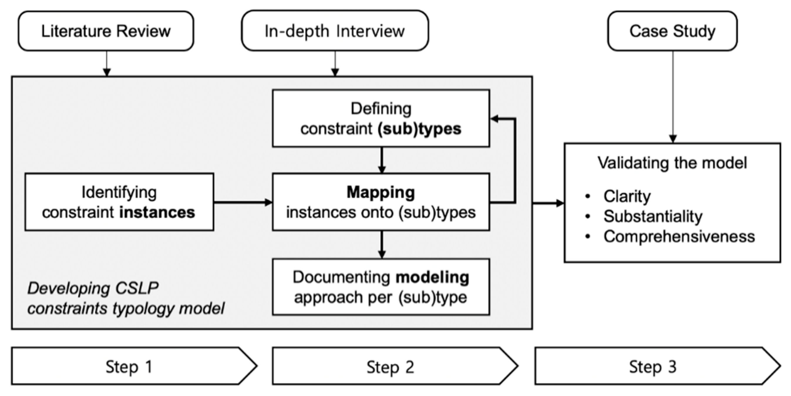
Since CSLP is generally done in a heuristic method based on the experience and intuition of experts, there are limitations to the construction of the actual CSLP constraint typology model only within the literature. Therefore, this study adopted the triangulation approach [42], which combines multiple research methods such as literature review, in-depth interviews, and case studies (Figure 2). Specifically, this study was carried out in the following three stages: (1) identification of constraints related to 11 temporary facilities, (2) mapping of these constraints onto appropriate constraint (sub)types according to their characteristics, and (3) validation of the clarity, substantiality, and comprehensiveness of the constraint typology models.
3.1. Identifying CSLP Constraints of Temporary Facilities
This stage aims to derive the CSLP constraints of 11 temporary facilities included in the research scope to enhance the practicality of the typology model to be developed. The derived constraints are instances of the typology model and serve as the criteria for determining whether the constraint type presented in the model can explain all constraints. To this end, the authors explored and defined constraints to be considered in the layout of each temporary facility based on CSLP manuals [43,44] and temporary facility specifications in addition to research papers regarding CSLP automation. In-depth interviews were then conducted with six CSLP experts (cumulative years of industry experience: 115 years; mean years of personal industry experience: 19 years) to derive additional constraints used in the actual field. In the interviews, research objectives and contents were introduced, and discussions were carried out about the approximate CSLP process and constraints considered at the site in which interviewees participate at present, the created construction site layout, the case of inappropriate temporary facility layout, and difficult parts observed in CSLP.
3.2. Mapping CSLP Constraints onto Constraint Types
This stage is aimed at defining the CSLP constraint types and subtypes and mapping the constraints (instances) of temporary facilities identified in the first stage onto the corresponding (sub)types. Since the CSLP typology model is designed not only to help human understanding but also to help model individual constraints in a computer-interpretable form, computational modeling methods for each constraint type are also presented in this study. For this, the CSLP types and subtypes were first defined based on the existing studies on the CSLP constraint classification, and each collected constraint instance was mapped onto appropriate (sub)types. In the process, the constraint typology was continuously modified, and this modification was terminated when all of the collected constraint instances belonged exclusively to one CSLP (sub)type. As a result, the final constraint typology model was obtained, and a computational modeling method that allows each constraint type to be checked by a computer and used in the CSLP automation model was then proposed.
3.3. Validating the Developed Constraint Typology Model
This stage aims to validate the developed CSLP constraint typology model in terms of clarity, substantiality, and comprehensiveness. Validation tests were conducted by four experts working at four different sites. First, clarity was measured using a five-point Likert scale that ranged from one (not clear at all) to five (very clear) regarding whether each constraint clearly conveyed the meaning. For the measurement of substantiality, experts were asked whether each constraint was actually taken into account in the CSLP process at each site to which the experts belonged or whether they think it is worth considering even though it was not considered for a specific reason. In addition, it was also checked whether such consideration appeared the same at multiple sites (that is, whether it is a commonly used constraint) used in validation. Comprehensiveness was measured by asking whether there were additional constraints in addition to the constraints included in the typology model. Meanwhile, additional opinions offered by experts during the validation process were used to complement the developed typology model.
4. A Constraint Typology Model for CSLP
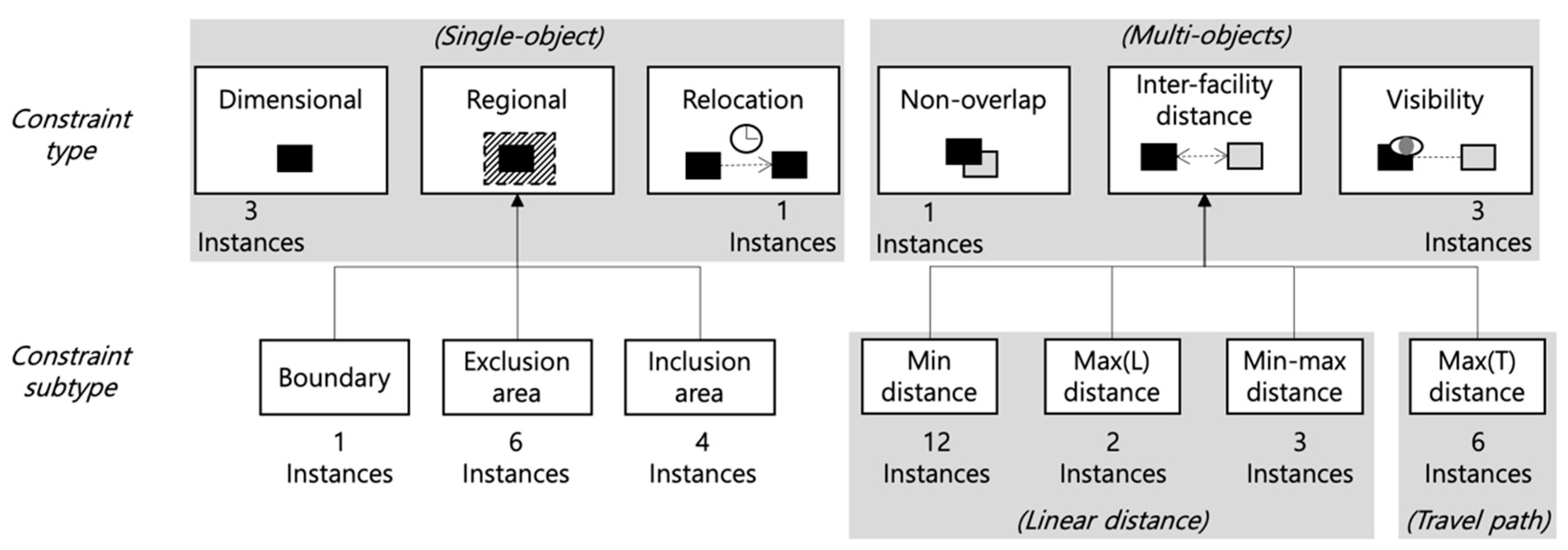
This section presents a constraint typology model that CSLP automation models can use for construction site layout optimization or validation of the created construction site layout (Figure 3). The proposed model includes the definition of six constraint types and seven subtypes, which characterize 42 constraint instances identified in 11 temporary facilities. Three constraint types (i.e., dimensional, regional, and relocation) concern a single object laid out alone, and the other three constraint types (i.e., non-overlap, inter-facility distance, and visibility) concern about relationships between multiple objects placed.
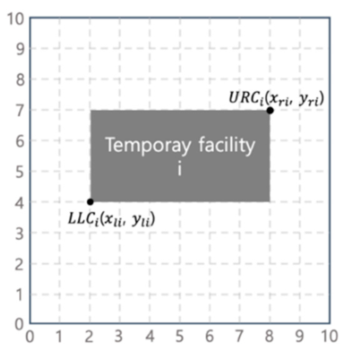
In order for CSLP automation models to derive practical results, it should be possible to create a construction site layout that complies with constraints during the optimization process. To do this, all constraints must be represented in a computer-interpretable form so that the CSLP automation models can examine the compliance with the constraints. The site space for laying out temporary facilities in CSLP automation models is generally composed of grid cells for the purpose of reducing the search space. The shape of the object is also often represented as a rectangle to simplify the calculation process. In general, one grid cell is the smallest region occupied by the object, and as the cell size decreases, the calculation time increases while the accuracy increases. The size of the cell can be adjusted according to the size of the site and temporary facilities as well as the accuracy sought by the planner [31,41]. Accordingly, in this study, the site is represented as a two-dimensional grid with an () coordinate system, and the origin is established at the lower left corner of the area. The temporary facility , represented as a rectangle, is expressed as the lower left corner of () (i.e., (, )) and the upper-right corner of () (i.e., (, )) according to Benjaoran and Peansupap [34] (Figure 4).
Meanwhile, the proposed typology model was supplemented according to the opinions of experts during the validation process. The opinions were categorized into five types as shown in Table 2. Then, opinions that required detailed modification of the constraints (CT1) (e.g., “The radius of T/C should be dealt along with the tip load.”) and comments on the choice of words or typos (CT2) (e.g., “It should be clearly determined whether the gate is for a vehicle or for a pedestrian.”) were reflected in the creation of this model. However, opinions the authors disagree with for a valid reason (CT3) (e.g., one expert gave a negative opinion on the necessity of a constraint, but other experts agree that the constraint is necessary), comments that do not fit the context or have already been reflected (CT4), and opinions whose meaning was not clear (CT5) were not reflected. Through this process, 33 comments (42%) out of 78 were finally reflected in the creation of the constraint typology model.
4.1. Dimensional Constraint
Dimensional constraints are related to the size (length, width, area), shape, and direction of the temporary facility to be laid out. Violations of this type of constraint can easily be checked by simply comparing the constraint with the parameters of the temporary facility object. However, it is often difficult to determine the constraint itself because the determination requires processing of multiple pieces of information about nearby objects, which are sometimes spatio-temporal. For example, all constraint instances identified in this study (Table 3) require determination of minimum width and area of the access road by processing vehicle information (e.g., turning radius and width) and location of obstacles in the transport route all together. Therefore, to check the dimensional type constraints efficiently, the required information needs to be identified and represented in a computer-interpretable form.
Since the review of these constraints makes it possible to secure enough space for the movement of vehicle, and to identify the optimal space required to support construction work in a limited site space, it helps to reduce congestion and enables smooth transportation within the site at the same time.
4.2. Regional Constraint
Regional constraints concern the region (i.e., site boundary and a specific enclosed area that exists on the site) in which temporary facilities are installed. In most cases, the enclosed area is present within the site, but it also often includes the area near the site. Regional constraints have three subtypes as follows:
- Boundary constraint to ensure that a temporary facility to be laid out is located inside the site boundaries
- Inclusion area constraint to ensure that a temporary facility to be laid out is placed only in a specific enclosed area
- Exclusion area constraint to ensure that a temporary facility to be laid out is not placed in a specific enclosed area
Regional constraints identified in this study are summarized in Table 4, and they comprise three constraints that are commonly applied to all temporary facilities and eight constraints that are applied to specific temporary facilities.
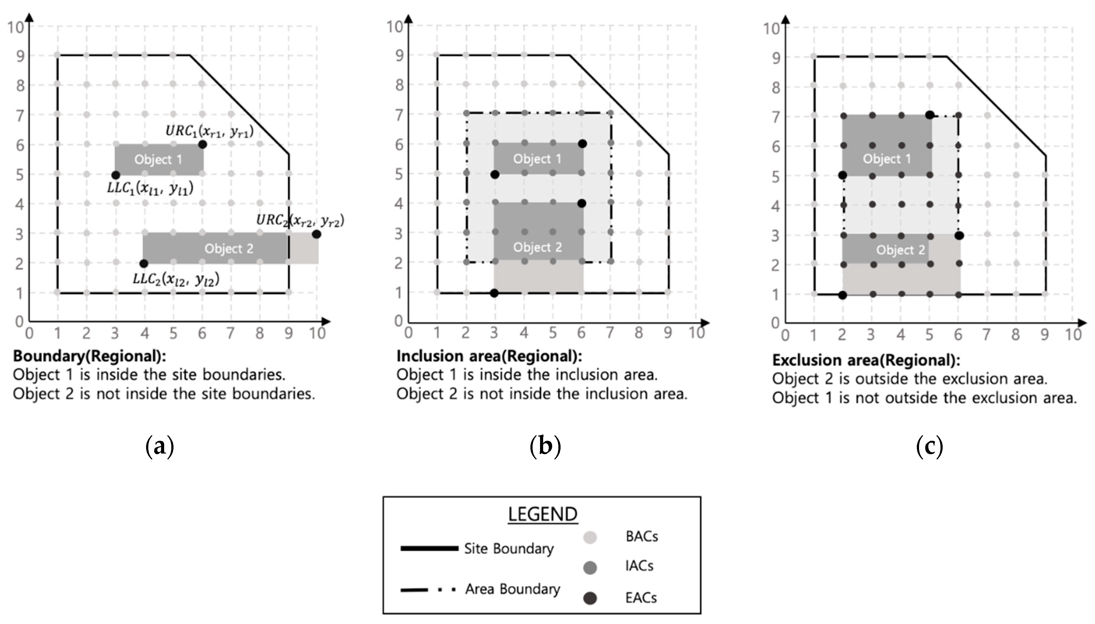
These constraints can be modeled through reference coordinates that the facility has and coordinate values held by the region of interest. First, the boundary constraint (Figure 5a) should satisfy the following equation so that the coordinates of all temporary facilities () can be included in the site boundary’s available coordinates () [34]:
Second, the inclusion area constraints (Figure 5b) should be placed to specific temporary facilities in the inclusion area coordinates (), and therefore the following equation should be satisfied:
Lastly, the exclusion area constraints (Figure 5c) should be placed so that a specific set of temporary facilities cannot be included in the exclusion area coordinates (), and therefore the following equation should be satisfied:
In addition, these constraints require certain site geometry information depending on the purpose of the constraints. For example, RG3 needs ground level information for measures to prevent floods, so a computer needs to set the area below the ground level as an exclusion area to disable the layout of temporary facilities. Therefore, site geometry information should be extracted automatically from the site layout. Extraction from computer-aided design (CAD) files can be performed using the method proposed by Osman et al. [22], and extraction from the BIM can be performed through the industry foundation classes (IFC) or the application programming interface (API) provided by commercial software such as Autodesk Revit.
4.3. Relocation Constraint
One constraint has been identified as the relocation constraint, which limits the number of relocations of the site office during consecutive construction phases prior to the framework construction (ID: RL1). Once a framework starts to be erected, a room inside the building that does not influence other works can be used as a site office. However, before the framework construction phase, if the number of the relocation is not limited, unnecessary work and costs are inevitably involved. This constraint needs to be checked when a phased or continuous CSLP automation model creates a construction site layout, and it can be performed by using a binary variable that changes when relocation occurs in two successive phases [45]—the sum of the binary variables between successive phases must not exceed the allowed relocation number. Solutions created by satisfying this constraint can be integrated with other evaluation factors (e.g., cost and travel distance) suggested in previous studies [7,36,45] to help determine the optimal location and timing for the site office to stay in one place for a long time.
4.4. Non-Overlap Constraint
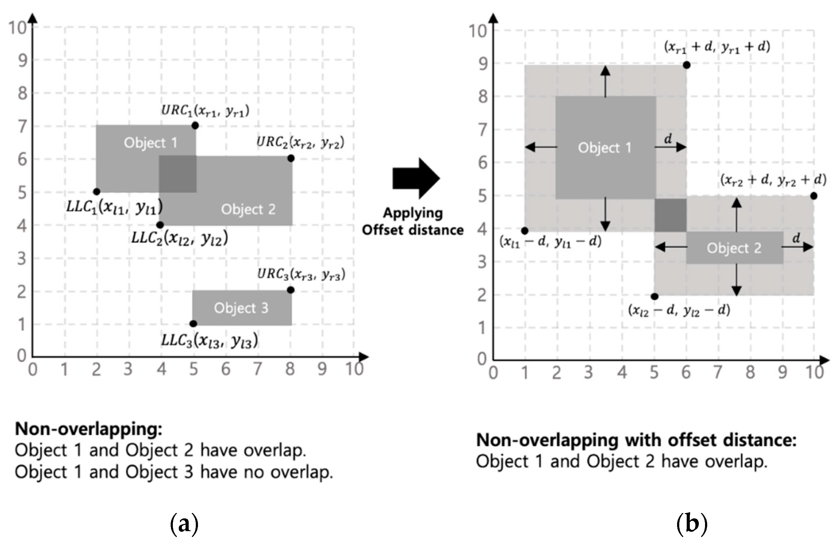
Non-overlap constraint prevents physical overlap between temporary facilities and other objects (ID: NO1). The minimum distance between the temporary facilities and other objects should be at least x(m) apart to prevent them from overlapping. To achieve this, the coordinates ), ) of different facilities i and j should satisfy the following equation as shown in Figure 6a:
However, it is also possible to set the offset distance to maintain a safety distance (buffer zone) between the temporary facilities and other objects (Figure 6b). To do this, the following equation should be satisfied as shown below:
This inequality is inspected only to check whether the safety distance is violated at the time of layout and is thus a necessary condition that must be satisfied before inter-facility distance constraints (explained in the following section) are checked by a computer.
4.5. Inter-Facility Distance Constraint
Inter-facility distance constraints limit the distance between temporary facilities and other objects for reasons such as safety, security, and accessibility. In this case, the distance may simply mean a physical distance but can also refer to travel distance in some cases. In addition, it was found to be a type of constraint that occupies the largest proportion among the constraints identified in this study as at least one was identified for each temporary facility (Table 5). Inter-facility distance constraint has four subtypes as follows:
- Min distance constraint to determine the minimum linear separation distance between the temporary facility to be laid out and other objects
- Max(L) distance constraint to determine the maximum linear distance between the temporary facility to be laid out and other objects
- Min–max distance constraint to ensure that the temporary facility to be laid out should be placed within a specific radius of other objects
- Max(T) distance constraint to determine the maximum distance based on the actual travel path between the temporary facility to be laid out and other objects
Most of the constraints exist as conditions to keep a separation distance between objects (i.e., min distance constraint). Incorrect reference point settings in these constraints can lead to completely different calculation results. Therefore, the reference point, which serves as a basis for calculation, should be set differently depending on the goal that each constraint pursues. For example, in IF11, the radius of the tower crane should be larger than the distance between the center of the crane and the farthest point of the structure. That is, reference points for the two objects should be set to measure the distance. In this context, different reference points, such as center-to-center (measuring the distance based on the center of each object), center-to-closest/farthest (measuring the distance between the center of one object and the closest/farthest point of the other object), and edge-to-edge (measuring the distance between the edges of each object) reference points can be used [33].
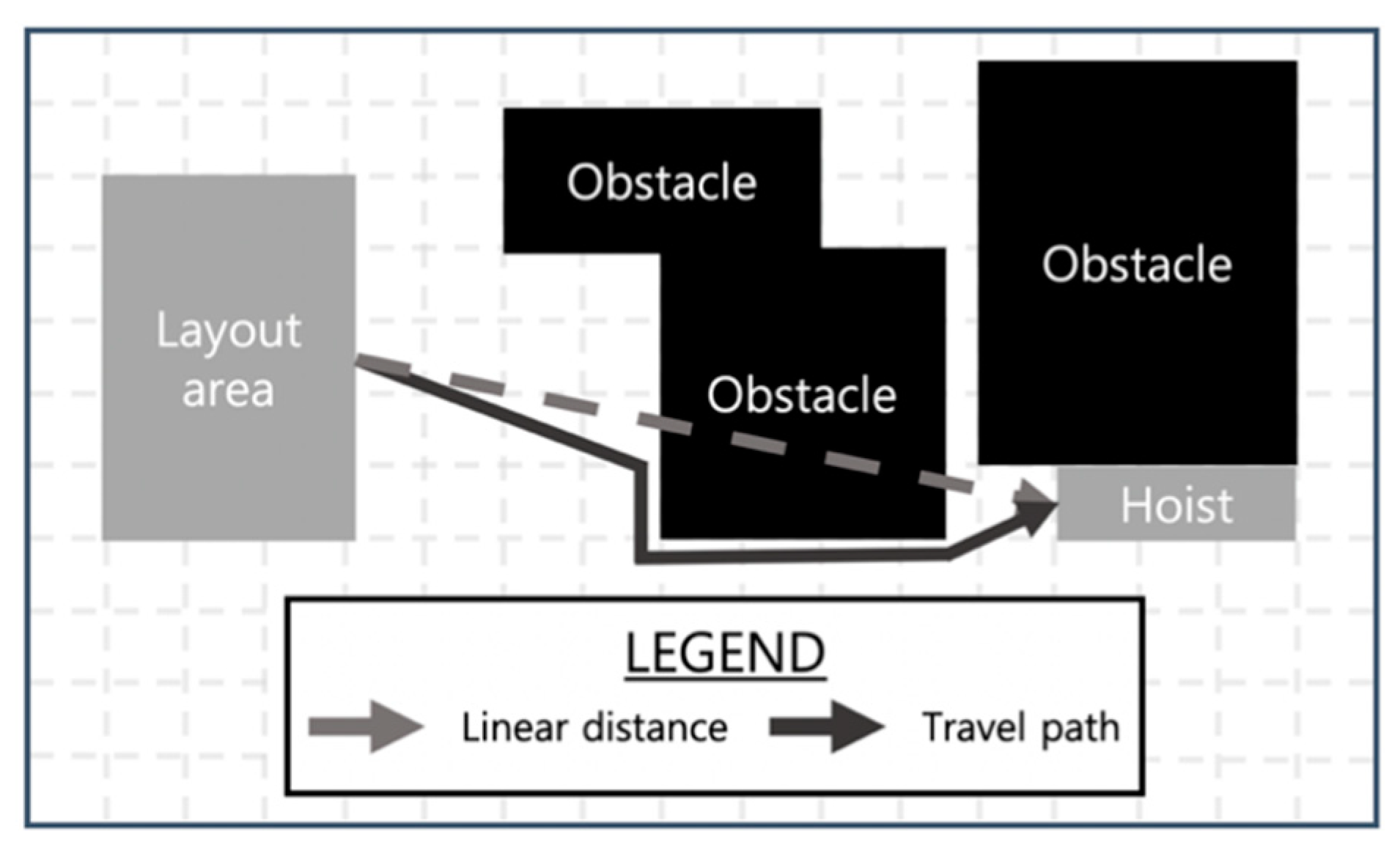
In addition, IF15 through IF20 have a direct impact on the travel distance of labor, equipment, and materials. Therefore, the distance should be calculated using the actual travel distance rather than the linear distance. Nevertheless, only the linear distance is used in most studies [36]. For example, in IF16, if the linear distance is used to calculate the distance between the laydown area outside the building and the closest hoist, then detours to avoid obstacles when moving from the laydown area to the hoist cannot be considered (Figure 7). This, in turn, leads to the incorrect layout of temporary facilities. In this connection, it is important to explore the actual path where real people or equipment are moving. Material types (e.g., heavy material, light material) and transport modes (e.g., person, forklift) should also be considered for estimating the movement [36]. For example, light material can be transported by labor and wheelbarrows regardless of the path. However, heavy material requires heavy equipment such as a forklift and can be transported only through paths with sufficient widths. Some algorithms, such as A* search algorithm [36] and Dijkstra’s algorithm [28], are notable and can be utilized to find the shortest travel path.
4.6. Visibility Constraint
Visibility constraints ensure visibility from temporary facilities to other objects or specific points on the site for management, safety, and security reasons. The visibility constraint instances identified in this study are summarized in Table 6.
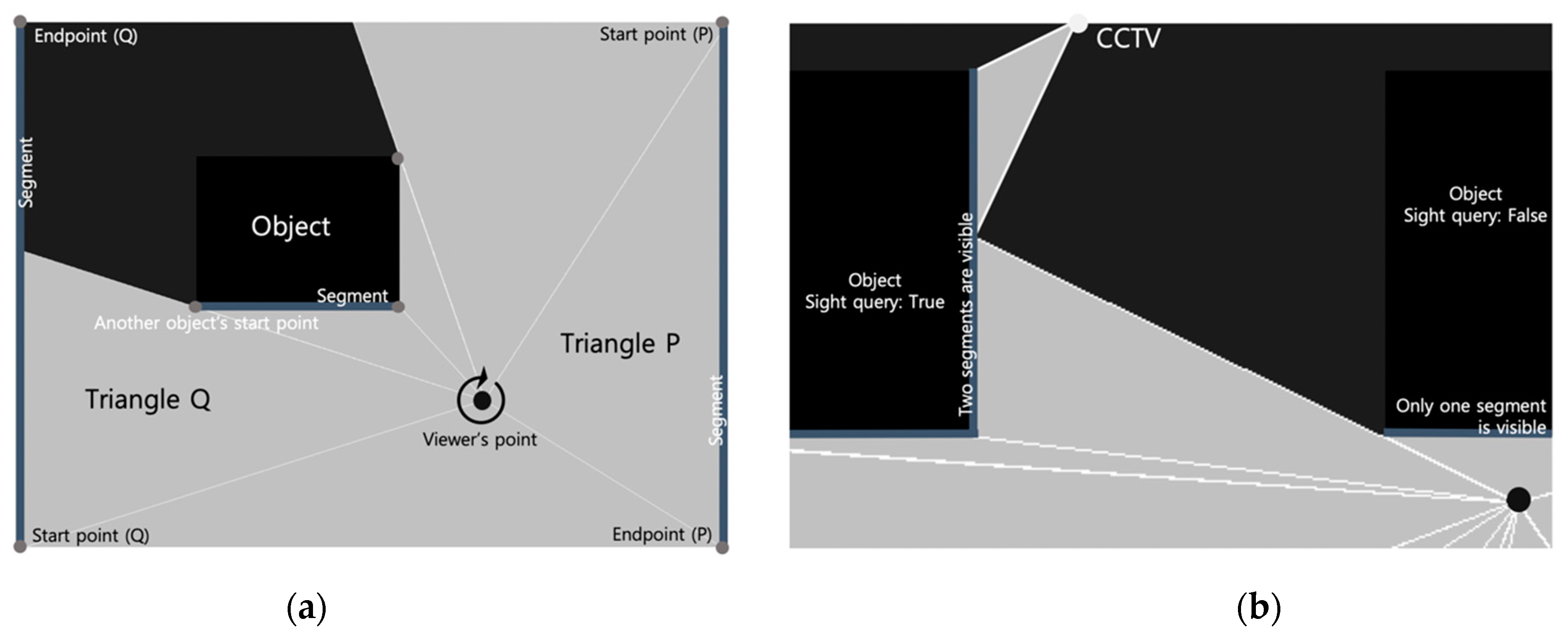
The visibility checking, that is, whether a subject is visible to viewers in space, can be performed using the raycasting approach. Specifically, visibility regions can be generated by three steps: first, sweep 360 degrees from the viewer’s point, projecting a light ray toward to start point and end point of all segments (site boundaries or site objects’ walls). Second, while sweeping, each time the start or end points of the segments closest to the viewer’s point are captured, a triangle consisting of vertices (the viewer’s point, start point, and end point) is filled as in Triangle P in Figure 8a. On the other hand, if the nearest segment is changed to another object’s segment before the end point of the original segment closest to the viewer’s point is captured, a triangle consisting of vertices (the viewer’s point, start point, and another object’s start point) is filled as in Triangle Q in Figure 8a. Third, iterate the second step until sweeping is completed. The set of these triangles is the visibility regions from the viewer’s point where the segment hidden from the viewer due to the presence of other objects is considered [46]. Furthermore, when a closed-circuit television (CCTV) is installed to cover the visibility, it should also be deemed a viewer that creates a visibility region. Once all visibility regions are set, actual checking of the visibility constraints can be made by implementing a sight query that returns a true value when at least two segments of the object are entirely visible without being blocked (Figure 8b).
5. Validation
The goal of this paper was to gather and classify constraints that are actually considered during the layout of the target temporary facilities for use in computational modeling of construction site layout planning. Therefore, as a validation study, three characteristics (i.e., clarity, substantiality, and comprehensiveness) of the CSLP constraints model were tested based on four actual CSLP cases with various uses and sizes (Table 7). Substantiality was tested through a comparison between the constraints actually considered in the cases and the constraints identified in this study. Clarity and comprehensiveness were tested through interviews with experts who participated in the cases. All experts had more than ten years of experience in the field of construction and had participated in more than two construction projects. Moreover, when temporary facilities are automatically laid out using a computer, construction site layout that cannot be applied in reality may be generated if the temporary facilities are located outside the site or overlap with other objects. To prevent this from occurring, the constraints RG1 and NO1, which must be included in CSLP, were omitted in the validation study.
First, the clarity of each constraint was measured by the experts who actually performed the surveyed CSLP projects. The clarity was evaluated on a 5-point Likert scale, and all constraints were found to obtain an average of 4.85 points (minimum: 4; maximum: 5; standard deviation: 0.27). This suggests that all identified constraints can be clearly understood by the construction site layout planners, and there will be little difficulty in transcribing the constraints in a computer-interpretable form.
Second, the substantiality of constraints was measured by asking whether each constraint was actually considered in multiple CSLP cases. Experts were asked to choose between O (considered at the site), △ (not considered at the site but worth considering), and X (never considered and not worth considering) for each constraint. When they thought some constraints were outside their expertise, they were asked to mark the constraints “NR” (not responded). The evaluation found that all constraints identified in this study could be considered O or △ in at least three CSLP cases. The finding means that the constraints identified in this study are substantial enough to be generally applied in CSLP of actual construction projects. However, depending on the project characteristics, there may be differences in the constraints considered by the planners. For example, regarding the IF8 constraints, it was confirmed that whether or not the tower crane can invade the road may depend on the level of permission of the administrative district. As another example, for VI2, it would be considered optimal if the office’s location is located where the site could be viewed as a whole, but if it is difficult due to the site conditions, there is also a possibility of using CCTV to solve this. These examples imply that these constraints are generally necessary, but sometimes it can be used as soft constraints depending on the nature of the construction projects.
Third, this study demonstrated the comprehensiveness of the typology model by explaining all identified constraints as instances of proposed constraint (sub)types. In addition, all respondents agreed that there were no additional constraints considered at CSLP. This suggests that this study presents a comprehensive typology model that can explain all constraints to be considered in the layout of temporary facilities.
6. Discussion
6.1. Evaluation Percentages by Constraint and Temporary Facility Types
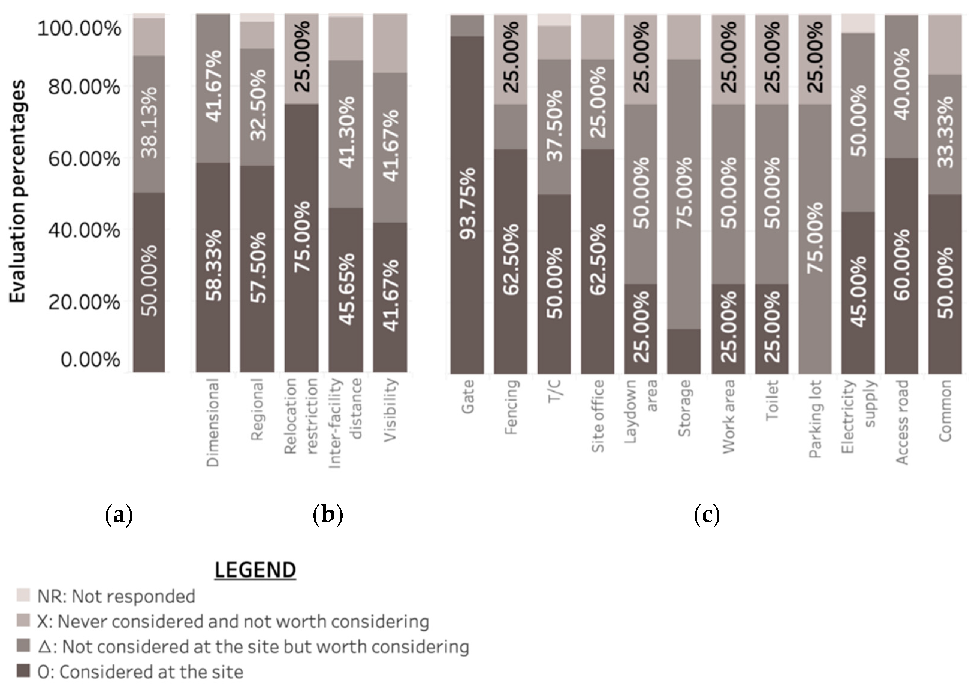
Figure 9 is a stacked bar graph showing how CSLP planners consider the constraints identified in this study when performing CSLP by types of constraints and temporary facility.
First of all, 88% of all constraints were considered or worth considering in actual CSLP cases. However, note that 43% of these constraints were not considered in reality. This may have been because some constraints pose difficulties in detailed inspections without the help of computers due to the complex relationship between objects (e.g., DI3, RG9, IF11, and VI3). For example, in checking DI3, the minimum width of the access road should be determined taking into account various factors simultaneously, such as the curvature of the road, surrounding obstacles, and the vehicle size. Insufficient consideration of these factors often leads to either narrow access roads that generate traffic issues on-site or unnecessarily wide access roads that reduce free areas for other facilities and logistics. Another reason might be that some constraints have a large number of objects that need to be checked, causing repetitions in evaluation (e.g., IF7 and VI3). For example, IF7 requires a planner to check separation distances between all objects on-site, and such repetition is time-consuming and even error-prone. Therefore, to increase the actual consideration rate of the constraints, automated and computer-assisted construction checking needs to be realized to complement current repetitive manual checking practices for various constraints.
As for constraint types, more than 90% of respondents said that the dimensional and regional-type constraints are to be considered, and more than half of them actually considered the constraints in their projects. It seems that the constraints have frequently been checked because these are closely related to civil complaints as well as smooth logistics and safety issues. Because the checking of these constraints still relies mostly on experience, intuition, and brainstorming of construction site layout planners, computer-based checking can help them review these constraints in an efficient and accurate way. Meanwhile, the percentage of actual consideration of inter-facility distance and visibility constraints was only 43% on average. This may be because they involve more than two objects in evaluation, which often requires complex or repetitive calculations. For example, the checking of VI3 can be quite complicated due to various factors such as the height and size of the objects. According to the interview, there were no cases in which a computer was used to examine the visibility. If the visibility checking and distance examination can be performed automatically using computer technologies, these types of constraints can actually be checked quickly, leading to quality improvement of construction site layout.
As for temporary facility types, more than 93% of respondents said that the constraints related to gates and access roads are worth considering, which is considerably higher than the percentage of other temporary facilities. However, the actual consideration rate of the access roads constraints was only 60%. This may be because gates often have a priority in CSLP due to their impact on materials and equipment logistics, traffic outside the site, and civil complaints. On the other hand, constraints of access roads (e.g., VI1 and DI3) often require vehicle movement information, which is difficult to track without the help of a computer, such as vehicle turning radius, vehicle width, and vehicle safety buffer zone [46]. Compared to other facilities, laydown areas, storages, work areas, toilets, and parking lots also have constraints that are worth considering but not actually considered in practice. Location of these facilities tends to be determined heuristically according to the situations of construction sites without systematic consideration of related constraints. In particular, the constraints of the parking lots were taken into account in no cases, although they could lead to improved worker productivity if assigned to a convenient location providing the shortest and safest path to the work area. Some experts argued that the main reason for this could be the low perceived importance of these facilities.
6.2. Constraint Checking for Optimizing Construction Site Layout
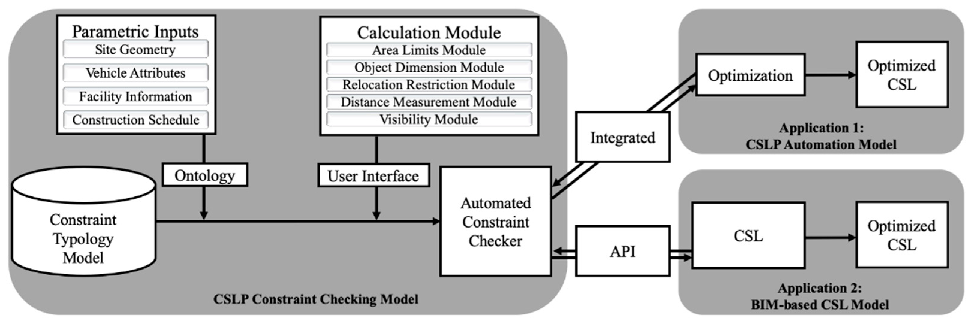
Construction site layout can be optimized with a level that can be used in actual construction projects if constraints of temporary facilities are identified comprehensively from real projects and classified into workable computer modeling approaches. In addition, it is possible to develop a system with a guided method through BIM-based interactions between humans and computers with the help of an automated constraint checker (Figure 10).
As mentioned before in Section 6.1, to identify the needed information for constraint compliance, required data such as complex relationships between objects or various variables (e.g., vehicles’ turning radius for checking access roads) should be specifically described based on ontology. Hence, it is necessary to build a custom ontology that captures needed model information that is used for constraint compliance. This ontology may include classes such as geometric information or relationship between objects of site elements, or classes that hold requirements for constraint check. In addition, to prevent the need to repeat the manual check of similar constraints multiple times for several temporary facilities, a calculation module for each constraint type should be created, and the data should be visually displayed to the user for easy access so that custom constraints created through them should be created easily by a user interface. Lastly, due to the nature of CSLP, a visualization tool that site planners can check and edit should be essential. This is necessary as a means of basic inspection, but this is also necessary because the location of temporary facilities tends to be heuristically tailored to the situation of the field without systematic consideration of related constraints.
Therefore, unlike construction site layout optimization systems suggested by many previous studies [6,24,27,34], the automated constraint checker consists of the constraints typology model (as a knowledge base), parametric inputs necessary for evaluation such as site geometry and vehicle attributes, and calculation modules for checking various types of constraints. As the typology model suggests the computational checking of constraints per type, all constraint instances are automatically checked once they are put into a type and related parametric inputs are provided. In addition, as the typology model functions as a knowledge base for construction site layout checking, an addition of constraints can be integrated easily into the model, which would increase the scalability of the automated constraint checker. The checker can be applied in two ways. First, it can be integrated into the optimization process of CSLP automation models to create a construction site layout that complies with all applied constraints. Second, it is possible to determine whether a construction site layout, represented in BIM, complies with all constraints through the use of API.
Ultimately, these applications can help to improve the practicality of the existing construction site layout models, and this, in turn, would lead to the minimization of human errors in the planning phase to make improvements in terms of cost and scheduling and industrial safety. To this end, the following further studies can be carried out:
- IFC model reinforcement for site object elements: To enable this model checker system, site objects and the relationships between the objects should be represented in a computer-interpretable form so that constraint checking algorithms can make use of them whenever they are needed. However, since they have not been sufficiently modeled in the IFC [15], further studies are needed to investigate site object modeling and reinforcing IFC accordingly.
- Development of a rule language: In order to enhance the accessibility of construction site layout planners to the automated constraint checker, research on a method to facilitate easier transcription is needed so that textual rules in a natural language can be intuitively applied to algorithms even without programming knowledge. This may require the development of an open-source rule language, which can support the planners to develop additional user-defined constraints.
7. Conclusions
This study contributes to the CSLP automation theories by providing a constraint typology model and suggesting computational modeling of each constraint type, which enables automated constraint checking for improving practicality of construction site layout optimization. The typology model was developed by applying the triangulation approach involving literature review, in-depth interviews with experts, and case studies. As a result, 42 constraint instances utilized in 11 temporary facilities were identified and mapped onto the following six constraint types:
- Dimensional constraints that are related to the size (length, width, area), shape, and direction of the temporary facilities to be laid out; although they can be easily checked through a comparison with the parameters of the temporary facility objects, additional computational modeling is often needed to determine reference values of the constraints themselves. This study identified three constraint instances for this type.
- Regional constraints that concern the region in which a temporary facility is allocated; the region includes the site boundaries and a specific enclosed area that exists at the site. This constraint is divided into three subtypes, i.e., boundary (one instances), inclusion area (four instances), and exclusion area (six instances) constraints. They can be modeled through a set of coordinate values occupied by the region and often require site geometry information for accurate evaluation.
- Relocation constraints that limit the number of relocations of the facilities during construction; they can be checked by using a binary variable whose value changes when relocation occurs in two consecutive phases. This study identified one constraint instance for this type.
- Non-overlap constraints that prevent physical overlap between temporary facilities and other objects; it is also possible to set the offset distance to allow a safety distance between the objects. This constraint type needs to be checked before inter-facility distance constraint checking because they are mandatory requirements for locating temporary facilities on site.
- Inter-facility distance constraints that limit the distance between temporary facilities and other objects for several reasons such as safety, security, and accessibility; this constraint is divided into four subtypes, i.e., min distance (12 instances), max(L) distance (two instances), max(T) distance (six instances), and min–max distance (three instances) constraints. The reference points for distance calculation should be set differently depending on the goal of constraints. In addition, travel path distance should be calculated based on estimation of the actual path that are affected by material types and transportation modes.
- Visibility constraints that examine the visibility from temporary facilities to other objects or a specific point on the site; this constraint can be checked using ray casting, which projects a light ray from the reference point and displays the visibility region. This study identified three constraint instances for this type.
This study is novel because it proposes a CSLP constraint typology model with clarity, substantiality, and comprehensiveness through the collection of the actual constraints required for the layout of major temporary facilities and classification of them according to the computational modeling approach. Findings of this study can be used for the construction site layout optimization process of most construction projects or in the check of compliance with the constraints of the existing BIM-based construction site layout model, thereby contributing to the CSLP automation and improvements in the practical applicability of the results. However, it also poses limitations in that the subjects for the collection of the constraints were limited. Further investigation of constraints from more cases with different characteristics, such as locations, uses, and sizes, would improve the model in terms of generality. Furthermore, it is needed to investigate the way each constraint (or a combination of constraints) affects construction site operation performances (e.g., time, safety, environment, quality, and costs). When planners are in a situation where multiple constraints are applied in the layout planning process, they can set a goal (e.g., performance) they want to prioritize and create a layout that can achieve it. For example, if time and cost are prioritized, an access road with a shorter length and minimum transportation cost can be created. If the focus is on a safe environment, vehicles or workers can work safely in areas where civil complaints probability are less. Therefore, it can be used to find an optimized layout for the planner’s intention in the trade-off process regarding the degree of performance. Development of the constraint typology model, along with continuous research on the aforementioned follow-up studies, would contribute to the deployment of CSLP automation models in practice. Such movement towards digital transformation of CSLP can help construction sites to have better layouts for people to work in a safer, more efficient, and more environmentally friendly way.
Author Contributions
Conceptualization, M.K. and T.W.K.; methodology, T.W.K.; validation, M.K.; formal analysis, M.K.; investigation, M.K.; data curation, M.K.; writing—original draft preparation, M.K.; writing—review and editing, H.-G.R. and T.W.K.; visualization, M.K.; supervision, T.W.K.; project administration, T.W.K.; funding acquisition, T.W.K. All authors have read and agreed to the published version of the manuscript.
Funding
This work was supported by Incheon National University Research Grant in 2020.
Institutional Review Board Statement
Not applicable.
Informed Consent Statement
Not applicable.
Data Availability Statement
The data presented in this study are available on request from the corresponding author (validation data). The data are not publicly available due to confidentiality agreement.
Conflicts of Interest
The authors declare no conflict of interest.
References
- Tommelein, B.I.D.; Member, A.; Levitt, R.E. Site-layout modeling: How can artificial intelligence help? J. Constr. Eng. Manag. 1993, 118, 594–611. [Google Scholar] [CrossRef]
- Sadeghpour, F.; Moselhi, O.; Alkass, S. A CAD-based model for site planning. Autom. Constr. 2004, 13, 701–715. [Google Scholar] [CrossRef]
- Thomas, H.R.; Ellis, R.D. Construction Site Management and Labor Productivity Improvement: How to Improve the Bottom Line and Shorten Project Schedules; American Society of Civil Engineers: Reston, VA, USA, 2017; ISBN 9780784480328. [Google Scholar] [CrossRef]
- Hegazy, T.M.; Elbeltagi, E. Simplified spreadsheet solutions: A model for site layout planning. Cost Eng. 2000, 42, 24–30. [Google Scholar]
- Dawood, N.; Marasini, R. Stockyard layout planning and management for the precast concrete products industry. Logist. Inf. Manag. 2001, 14, 328–337. [Google Scholar] [CrossRef]
- Mawdesley, M.J.; Al-jibouri, S.H.; Yang, H. Genetic algorithms for construction site layout in project planning. J. Constr. Eng. Manag. 2002, 128, 418–426. [Google Scholar] [CrossRef]
- El-Rayes, K.; Khalafallah, A. Trade-off between safety and cost in planning construction site layouts. J. Constr. Eng. Manag. 2005, 131, 1186–1195. [Google Scholar] [CrossRef] [Green Version]
- Elgendi, E.M.O. An Automated Dynamic Site Layout Planning System—A Case Study of Egypt; University of Salford: Manchester, UK, 2016. [Google Scholar]
- Tawfik, H.; Fernando, T. A simulation environment for construction site planning. Proc. Int. Conf. Inf. Vis. 2001, 199–204. [Google Scholar] [CrossRef]
- Gómez, A.; Fernández, Q.I.; De la García, D.F.; García, P.J. Using genetic algorithms to resolve layout problems in facilities where there are aisles. Int. J. Prod. Econ. 2003, 84, 271–282. [Google Scholar] [CrossRef]
- Sadeghpour, F.; Moselhi, O.; Alkass, S. Dynamic planning for site layout. Proc. Annu. Conf. Can. Soc. Civ. Eng. 2002, 2002, 575–579. [Google Scholar]
- Abourizk, S. Role of simulation in construction engineering and management. J. Constr. Eng. Manag. 2010, 136, 1140–1153. [Google Scholar] [CrossRef]
- Schwabe, K.; König, M.; Teizer, J. BIM applications of rule-based checking in construction site layout planning tasks. In Proceedings of the International Symposium on Automation and Robotics in Construction, Auburn, AL, USA, 18–21 July 2016; pp. 209–217. [Google Scholar] [CrossRef] [Green Version]
- Fathy, A.M. Genetic algorithms for two-phase construction dynamic site layout. RISK 2016 2016. [Google Scholar] [CrossRef]
- Schwabe, K.; Teizer, J.; König, M. Applying rule-based model-checking to construction site layout planning tasks. Autom. Constr. 2019, 97, 205–219. [Google Scholar] [CrossRef]
- Abdel-Fattah, A. Dynamic Site Layout Planning Model. Univ. Calg. 2013, 225. [Google Scholar] [CrossRef]
- Song, J.; Lee, J.-K.; Choi, J.; Kim, I. Deep learning-based extraction of predicate-argument structure (PAS) in building design rule sentences. J. Comput. Des. Eng. 2020, 7, 1–14. [Google Scholar] [CrossRef]
- Yeh, I.C. Construction-site layout using annealed neural network. J. Comput. Civ. Eng. 1995, 9, 201–208. [Google Scholar] [CrossRef]
- Elbeltagi, E.; Hegazy, T.; Eldosouky, A. Dynamic layout of construction temporary facilities considering safety. J. Constr. Eng. Manag. 2004, 130, 534–541. [Google Scholar] [CrossRef]
- Tam, C.M.; Thomas, K.L.; Tong, W.K.W.C. Genetic algorithm for optimizing supply locations around tower crane. J. Constr. Eng. Manag. 2002, 127, 315–321. [Google Scholar] [CrossRef]
- Tam, C.M.; Tong, T.K.L.; Leung, A.W.T.; Chiu, G.W.C. Site layout planning using nonstructural fuzzy decision support system. J. Constr. Eng. Manag. 2002, 128, 220–231. [Google Scholar] [CrossRef] [Green Version]
- Osman, H.M.; Georgy, M.E.; Ibrahim, M.E. A hybrid CAD-based construction site layout planning system using genetic algorithms. Autom. Constr. 2003, 12, 749–764. [Google Scholar] [CrossRef]
- Khalafallah, A.; El-Rayes, K. Minimizing Construction-Related Security Risks during Airport Expansion Projects. J. Constr. Eng. Manag. 2008, 9364, 333–341. [Google Scholar] [CrossRef]
- Zhou, F.; Abourizk, S.M.; AL-Battaineh, H. Optimisation of construction site layout using a hybrid simulation-based system. Simul. Model. Pract. Theory 2009, 17, 348–363. [Google Scholar] [CrossRef]
- Ning, X.; Lam, K.C.; Lam, M.C.K. Dynamic construction site layout planning using max-min ant system. Autom. Constr. 2010, 19, 55–65. [Google Scholar] [CrossRef]
- Ning, X.; Lam, K.C.; Lam, M.C.K. A decision-making system for construction site layout planning. Autom. Constr. 2011, 20, 459–473. [Google Scholar] [CrossRef]
- Yahya, M.; Saka, M.P. Construction site layout planning using multi-objective artificial bee colony algorithm with Levy flights. Autom. Constr. 2014, 38, 14–29. [Google Scholar] [CrossRef]
- Hammad, A.W.A.; Akbarnezhad, A.; Rey, D. A multi-objective mixed integer nonlinear programming model for construction site layout planning to minimise noise pollution and transport costs. Autom. Constr. 2016, 61, 73–85. [Google Scholar] [CrossRef]
- Abotaleb, I.; Nassar, K.; Hosny, O. Layout optimization of construction site facilities with dynamic freeform geometric representations. Autom. Constr. 2016, 66, 15–28. [Google Scholar] [CrossRef]
- Farmakis, P.M.; Chassiakos, A.P. Dynamic Multi-objective Layout Planning of Construction Sites. Procedia Eng. 2017, 196, 674–681. [Google Scholar] [CrossRef]
- Razavialavi, S.; Abourizk, S. Genetic Algorithm-Simulation Framework for Decision Making in Construction Site Layout Planning. J. Constr. Eng. Manag. 2017, 143, 1–13. [Google Scholar] [CrossRef]
- Hammad, A.W.A. A multi-objective construction site layout planning problem solved through integration of location and traffic assignment models integration of location and traffic assignment models. Constr. Manag. Econ. 2019, 38, 756–772. [Google Scholar] [CrossRef]
- Razavialavi, S. Construction Site Layout Planning Using Simulation. Univ. Alberta 2016. [Google Scholar] [CrossRef]
- Benjaoran, V.; Peansupap, V. Grid-based construction site layout planning with Particle Swarm Optimisation and Travel Path Distance. Constr. Manag. Econ. 2019, 38, 673–688. [Google Scholar] [CrossRef]
- Easa, S.M.; Hossain, K.M.A. New mathematical optimization model for construction site layout. J. Constr. Eng. Manag. 2008, 134, 653–662. [Google Scholar] [CrossRef]
- Kumar, S.S.; Cheng, J.C.P. A BIM-based automated site layout planning framework for congested construction sites. Autom. Constr. 2015, 59, 24–37. [Google Scholar] [CrossRef]
- Abune’meh, M.; El Meouche, R.; Hijaze, I.; Mebarki, A.; Shahrour, I. Optimal construction site layout based on risk spatial variability. Autom. Constr. 2016, 70, 167–177. [Google Scholar] [CrossRef]
- Yi, W.; Chi, H.L.; Wang, S. Mathematical programming models for construction site layout problems. Autom. Constr. 2018, 85, 241–248. [Google Scholar] [CrossRef]
- Zouein, P.P.; Tommelein, I.D. Dynamic layout planning using a hybrid incremental solution method. J. Constr. Eng. Manag. 1999, 125, 400–408. [Google Scholar] [CrossRef] [Green Version]
- Xu, J.; Liu, Q.; Lei, X. A fuzzy multi-objective model and application for the discrete dynamic temporary facilities location planning problem. J. Civ. Eng. Manag. 2016, 22, 357–372. [Google Scholar] [CrossRef]
- El-Rayes, K.; Said, H. Dynamic site layout planning using approximate dynamic programming. J. Comput. Civ. Eng. 2009, 23, 119–127. [Google Scholar] [CrossRef]
- Taylor, J.E.; Dossick, C.S.; Garvin, M. Meeting the burden of proof with case study research. J. Constr. Eng. Manag. 2011, 137, 303–311. [Google Scholar] [CrossRef]
- Sutt, J.; Irene, L.; Müürsepp, O. The Engineer’s Manual of Construction Site Planning; John Wiley & Sons: Hoboken, NJ, USA, 2013; ISBN 9781118556092. [Google Scholar]
- Schach, R.; Otto, J. Baustelleneinrichtung; Teubner: Wiesbaden, Germany, 2008; ISBN 9783658160654. [Google Scholar]
- Huang, C.; Wong, C.K. Optimisation of site layout planning for multiple construction stages with safety considerations and requirements. Autom. Constr. 2015, 53, 58–68. [Google Scholar] [CrossRef]
- Lin, J.J.C.; Yang, C.E.; Hung, W.H.; Kang, S.C. Accessibility evaluation system for site layout planning—A tractor trailer example. Vis. Eng. 2013, 1, 1–11. [Google Scholar] [CrossRef] [Green Version]
Figure 1.
Frequency of temporary facilities appeared in construction site layout planning (CSLP) automation papers.
Figure 1.
Frequency of temporary facilities appeared in construction site layout planning (CSLP) automation papers.

Figure 2.
Overview of research methods.

Figure 3.
CSLP constraints types and subtypes.

Figure 4.
Representation of grid cells and temporary facilities on site.

Figure 5.
Regional constraint: boundary (a), inclusion area (b), and exclusion area (c) constraints.
Figure 5.
Regional constraint: boundary (a), inclusion area (b), and exclusion area (c) constraints.

Figure 6.
Non-overlap constraint: (a) non-overlapping and (b) non-overlapping with offset constraints.
Figure 6.
Non-overlap constraint: (a) non-overlapping and (b) non-overlapping with offset constraints.

Figure 7.
Linear and travel path distance algorithms for inter-facility distance constraint.

Figure 8.
Checking visibility constraints: raycasting approach (a) and sight query algorithm (b).

Figure 9.
Evaluation percentages in overall (a), by constraint types (b), and by temporary facilities (c).
Figure 9.
Evaluation percentages in overall (a), by constraint types (b), and by temporary facilities (c).

Figure 10.
Applying a constraint checker for optimizing construction site layout.

Table 2.
Comments on constraints typology model and author responses.
| Comment Type Code | Comment Type Description | Number of Comments | % of Total | Model Modified |
|---|---|---|---|---|
| CT1 | Substantive comment that required modification has been provided | 23 | 29% | Yes |
| CT2 | Typo, format error, or word choice issue | 10 | 13% | Yes |
| CT3 | Authors disagreed with the comment for a valid reason | 6 | 8% | No |
| CT4 | Comment is out of context or has already been reflected in the context. | 35 | 45% | No |
| CT5 | Meaning of comment was not clear | 4 | 5% | No |
| Total | 78 | 100% | - |
Table 3.
Dimensional type constraints identified in this study.
| ID | Subtype | Facility | Constraints |
|---|---|---|---|
| DI1 | N/A | Access road | If there is a blind alley at the site (or in front of the gate), at least x(m) × y(m) of the access road is needed to make the vehicle rounding section. |
| DI2 | N/A | Access road | The width of a single/two-lane access road should be at least x(m)/y(m), respectively, considering vehicles used on the site. |
| DI3 | N/A | Access road | For the turning radius of the vehicle, the width of the road should be at least x(m) in a curved access road, taking into account the vehicles used on the site. |
Table 4.
Regional type constraints identified in this study.
| ID | Subtype | Facility | Constraints |
|---|---|---|---|
| RG1 | Boundary | Common | TFs should be laid out only inside the site. |
| RG2 | Exclusion area | Common | TFs should be placed only in an area that is more than x(m) away from the property line. |
| RG3 | Exclusion area | Common | For measures to prevent floods, TFs should be laid out in an area x(m) higher than ground level. |
| RG4 | Exclusion area | Electricity supply | Temporary transformers should be placed away from work areas where water is heavily used or low-lying areas where flooding is expected. |
| RG5 | Exclusion area | Electricity supply | Temporary transformers should be placed away from areas where many people come in and out. |
| RG6 | Exclusion area | Gate | The gate should be placed away from areas where civil complaints are expected. |
| RG7 | Exclusion area | Work area | The work area should be placed away from areas where civil complaints are expected. |
| RG8 | Inclusion area | Electricity supply | Temporary transformers are placed in an area inside x(m) from the location of the power receiving system approved by authority. |
| RG9 | Inclusion area | Electricity supply | Temporary transformers should be placed close to the area where the facility electric capacity is heavily used. |
| RG10 | Inclusion area | Gate | The gate should be placed in areas with less impact on vehicle flow on adjacent roads. |
| RG11 | Inclusion area | T/C | The tower crane should be placed in an area where there is a place for a mobile crane to be located while dismantling things using the mobile crane. |
Table 5.
Inter-facility distance constraints identified in this study.
| ID | Subtype | Facility | Constraints |
|---|---|---|---|
| IF1 | Min | Access road | All TFs should be separated at least x(m) from the access road. |
| IF2 | Min | Common | TFs should be separated at least x(m) from the structure. |
| IF3 | Min | Fencing | There should be at least x(m) separation distance between the fencing and the access road. |
| IF4 | Min | Fencing | The distance between the fencing and the TF should be at least x(m) apart. |
| IF5 | Min | Gate | The gate should be placed at least x(m) away from obstacles around the road so that they cannot interfere with entrance/exit through the gate. |
| IF6 | Min | Site office | The office should be separated at least x(m) from the structure to be built. |
| IF7 | Min | Storage | The storage should be separated at least x(m) from the structure to be built. |
| IF8 | Min | T/C | The radius of the tower crane should not invade adjacent ground or adjacent roads. |
| IF9 | Min | T/C | To prevent the risk of falling objects, certain TFs should be located outside the dangerous zone caused by the crane’s swing radius. |
| IF10 | Min | T/C | The distance between a tower crane and surrounding obstacles should be larger than the length(m) of the main jib with some offset. |
| IF11 | Min | T/C | The tower crane should reach all parts of the structure. |
| IF12 | Min | T/C | When the self-weight of the crane is greater than x(ton), the crane should be separated from the excavation pit by at least a safety distance of y(m). |
| IF13 | Max(L) | Elec. supply | The distance between the temporary transformer and the TF that consumes electricity cannot exceed x(m). |
| IF14 | Max(L) | Gate | The gate should be adjacent to the outside road. |
| IF15 | Max(T) | Laydown area | The distance between the outside laydown area and the edge of the nearest access road should be up to x(m). |
| IF16 | Max(T) | Laydown area | The outside laydown area should be within a maximum of x(m) from the nearest hoist. |
| IF17 | Max(T) | Parking lot | The outside parking lot should be located within a maximum of x(m) from the nearest gate. |
| IF18 | Max(T) | Site office | The first site office should be located within a maximum of x(m) from the gate. |
| IF19 | Max(T) | Toilet | The distance between the toilet and the work area should be x(m) or less. |
| IF20 | Max(T) | Work area | The relevant work areas should be located close to each other regardless of a change in time |
| IF21 | Min–max | Laydown area | The laydown area outside the building should be located within the radius of the crane. |
| IF22 | Min–max | T/C | Given the self-weight of the lifting object and the tip load of the crane, TFs associated with the use of the crane should be located within the radius of the crane. |
| IF23 | Min–max | T/C | When multiple cranes are used, adjacent cranes should have shared working area to distribute the lifting loads. |
Table 6.
Visibility constraints identified in this study.
| ID | Subtype | Facility | Constraints |
|---|---|---|---|
| VI1 | N/A | Access road | Drivers should ensure visibility of at least x(m) on single-lane roads and at least y(m) on two-lane roads. |
| VI2 | N/A | Site office | The office should be located in a place where the entire site can be viewed. |
| VI3 | N/A | Storage | The storage should be in a location visible from the security office. |
Table 7.
Project profiles used in validation study.
| Case 1 | Case 2 | Case 3 | Case 4 | |
|---|---|---|---|---|
| Use | Apartment (residential) | Apartment-style factory | Residential- commercial complex | Commercial facilities |
| Construction cost | USD 223M | USD 160M | USD 144M | USD 122M |
| Site area | 56,863 m2 | 33,000 m2 | 19,196 m2 | 14,997 m2 |
| Buildings | 9 buildings | 1 building | 4 buildings | 2 buildings |
| Structure | RC | PC + RC | RC | RC |
| Stories | 37 | 13 | 40 | 33 |
Publisher’s Note: MDPI stays neutral with regard to jurisdictional claims in published maps and institutional affiliations. |
© 2021 by the authors. Licensee MDPI, Basel, Switzerland. This article is an open access article distributed under the terms and conditions of the Creative Commons Attribution (CC BY) license (http://creativecommons.org/licenses/by/4.0/).
Share and Cite
MDPI and ACS Style
Kim, M.; Ryu, H.-G.; Kim, T.W. A Typology Model of Temporary Facility Constraints for Automated Construction Site Layout Planning. Appl. Sci. 2021, 11, 1027. https://0-doi-org.brum.beds.ac.uk/10.3390/app11031027
AMA Style
Kim M, Ryu H-G, Kim TW. A Typology Model of Temporary Facility Constraints for Automated Construction Site Layout Planning. Applied Sciences. 2021; 11(3):1027. https://0-doi-org.brum.beds.ac.uk/10.3390/app11031027
Chicago/Turabian StyleKim, Minguk, Han-Guk Ryu, and Tae Wan Kim. 2021. "A Typology Model of Temporary Facility Constraints for Automated Construction Site Layout Planning" Applied Sciences 11, no. 3: 1027. https://0-doi-org.brum.beds.ac.uk/10.3390/app11031027
Note that from the first issue of 2016, this journal uses article numbers instead of page numbers. See further details here.