
Study on Time Reversal Maximum Ratio Combining in Underwater Acoustic Communications
by
Anbang Zhao
1,2,3,4,5, 
Caigao Zeng
1,2,3,
Juan Hui
1,2,3,*,
Keren Wang
1,2,3 and
Kaiyu Tang
1,2,3 1
Acoustic Science and Technology Laboratory, Harbin Engineering University, Harbin 150001, China
2
Key Laboratory of Marine Information Acquisition and Security, Harbin Engineering University, Ministry of Industry and Information Technology, Harbin 150001, China
3
College of Underwater Acoustic Engineering, Harbin Engineering University, Harbin 150001, China
4
National Key Laboratory of Science and Technology on Underwater Acoustic Antagonizing, China State Shipbuilding Corporation Systems Engineering Research Institute, Beijing 100036, China
5
College of Information Science and Technology, Tibet University, Lhasa 850000, China
*
Author to whom correspondence should be addressed.
Appl. Sci. 2021, 11(4), 1509; https://0-doi-org.brum.beds.ac.uk/10.3390/app11041509
Submission received: 7 January 2021
/
Revised: 28 January 2021
/
Accepted: 5 February 2021
/
Published: 7 February 2021
(This article belongs to the Special Issue Underwater Acoustic Communications and Networks)
Abstract
:Time reversal (TR) can achieve temporal and spatial focusing by exploiting spatial diversity in complex underwater environments with significant multipath. This property makes TR useful for underwater acoustic (UWA) communications. Conventional TR is realized by performing equal gain combining (EGC) on the single element TR output signals of each element of the vertical receive array (VRA). However, in the actual environment, the signal-to-noise ratio (SNR) and the received noise power of each element are different, which leads to the reduction of the focusing gain. This paper proposes a time reversal maximum ratio combining (TR-MRC) method to process the received signals of the VRA, so that a higher output SNR can be obtained. The theoretical derivation of the TR-MRC weight coefficients indicates that the weight coefficients are only related to the input noise power of each element, and are not affected by the multipath structure. The correctness of the derivation is demonstrated with the experimental data of the long-range UWA communications conducted in the South China Sea. In addition, the experimental results illustrate that compared to the conventional TR, TR-MRC can provide better performance in terms of output SNR and bit error rate (BER) in UWA communications.
1. Introduction
Underwater acoustic (UWA) channels are considered one of the most challenging wireless communication channels [1,2]. Significant multipath causes time delay spread and severe distortion on the communication signals, resulting in inter-symbol interference (ISI). Acoustic propagation loss and marine environmental noise reduce the signal-to-noise ratio (SNR) of the signals, thereby leading to high bit error rate (BRE) and degrading communication performance.
Time reversal (TR) has the properties of temporal and spatial focusing, corresponding to phase conjugation technology in the frequency domain [3]. The temporal focusing can suppress the multipath spreads of the signals and mitigate the ISI. The spatial focusing capability can obtain the spatial gain of the array, achieve a high output SNR, and thereby improve the communication performance. TR is divided into two types, active [4,5,6] and passive [7,8,9,10,11], from the perspective of implementation. To achieve active TR, a two-way transmission and reception need to be established, while in the passive mode, only a one-way propagation is required and then the TR is realized at the receiving end through signal processing means. Thus, passive TR is more practical and widely used in UWA communications. Passive TR communication was first proposed by Dowling [12], and it was demonstrated by a shallow water communication experiment based on a 14-element vertical receive array (VRA) [9]. In practice, there are still some residual ISI after TR combining. References [1,13,14,15] used a single-channel decision feedback equalizer [16] to eliminate the residual ISI after TR combining, thereby significantly improving the performance of TR communications. The above-mentioned TR used equal gain combining (EGC) [17] to combine the single element TR output signals of each array element. However, in the actual marine environment, both the SNR and noise power of each element are not consistent so that time reversal equal gain combining (TR-EGC) is not the best choice. In this case, we propose a time reversal maximum ratio combining (TR-MRC) method, which uses maximum ratio combining (MRC) [17,18] to combine the TR output signals of each element, so as to further improve the performance of TR communications in terms of output SNR and BRE. Generally, the weight coefficients of conventional MRC are calculated by estimating the signal amplitudes and noise power [17,18]. This paper proves through theoretical derivation that the weight coefficients of TR-MRC are only related to the received noise power of each array element, so there is no need to estimate the amplitudes of the signals, which greatly simplifies the calculation of the weight coefficients and makes the TR-MRC method more practical. Finally, we use the experimental data of long-range pattern time delay shift coding (PDS) [19,20,21] UWA communications conducted in the South China Sea to investigate the performance of TR-MRC.
This paper is organized as follows. Section 2 introduces the basic theory of TR-MRC, and analyzes the focusing gain and derives the weight coefficients. In Section 3, the communications experiment is described, and the experimental results are discussed to analyze the performance of TR-MRC. Section 4 summarizes the conclusions.
2. Theory of TR-MRC
2.1. Principles of TR
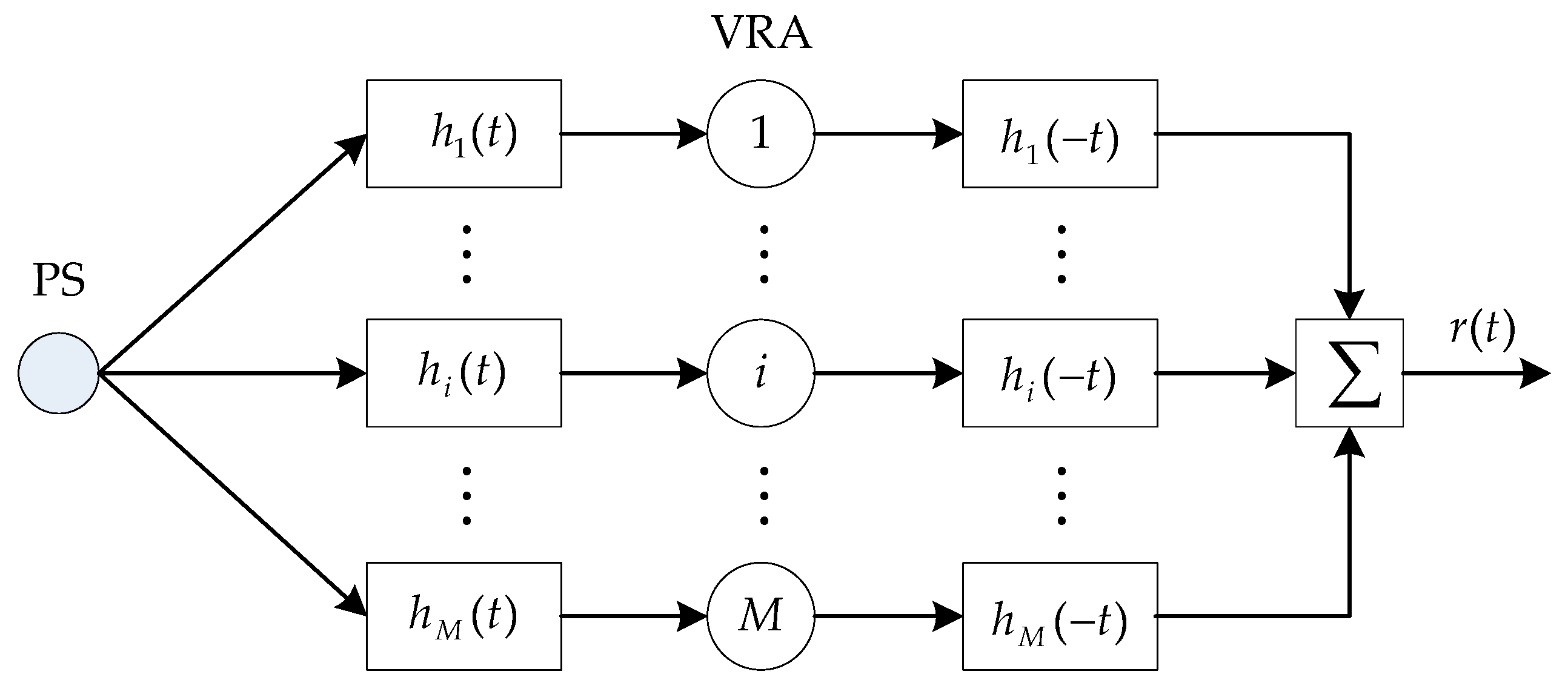
TR can adaptively match the UWA channels without any prior knowledge of the environment to achieve temporal and spatial focusing. Figure 1 shows the block diagram of a conventional TR combining. The received signals of the M-element VRA are first processed using the single element TR, and then they are combined by EGC method, so that the original signal transmitted from the probe source (PS) is recovered.
When a known signal is transmitted from a PS through the ocean channel, the signal received by the ith receiver of the VRA can be expressed as:
where:
is the channel impulse response (CIR), is the number of the paths between the PS and the ith receiver, and are the amplitude and time delay of the jth path, and is the received noise.
Firstly, the received signal of each element is subjected to a single element TR processing, that is, the received signal is convolved with the time-reversed channel . This processing makes the multipath signals superimpose coherently at the same time, while the noises superimpose incoherently with different time delays. It can be seen that TR achieves temporal focusing. Therefore, the TR output signal of each array element can be written as:
where:
where is the amplitude of the signal component and is the TR output noise.
Then the output signals of each receiver are combined using the EGC method to obtain the final output signal:
It can be seen from Equation (5) that after TR combining, all the multipath signals received by the VRA are coherently superimposed to achieve spatial focusing, while the noises are incoherently superimposed, so the output SNR is improved. However, in the actual marine environment, the SNRs and noise power of the TR outputs of the receivers at different depths are different. In this case, the spatial focusing gain obtained by combining the TR output signals of each element using the EGC method is not the best. Therefore, this paper proposes using the MRC method to combine the TR output signals, and then Equation (5) can be rewritten as:
where is the TR-MRC weight coefficient.
2.2. Focusing Gain and Weight Coefficients of TR-MRC
The input SNR of the received signal of a single receiver is defined as the ratio of the strongest multipath signal power to the noise power. For the convenience of calculation, we assume that the noise is Gaussian white noise, which is uncorrelated and statistically independent at any two different moments. In addition, it can be considered that the noises received by different array elements are also uncorrelated and statistically independent. According to Equation (1), the input SNR of the ith receiver can be obtained as:
where is the signal power of , is the variance of and denotes the received noise power, and represents the maximum value in the set.
After single element TR processing is performed on the signal of each element, the output SNR of a single array element can be calculated as:
where is the variance of and represents the output noise power of a single element TR. Since the noise in Equation (4) is uncorrelated and statistically independent at any two different moments, the output noise power of the single element TR can be calculated as:
Incorporating Equations (4) and (9) into Equation (8), we can get the output SNR of a single element TR as:
Therefore, combining Equation (7) with (10), the focusing gain of a single element TR can be obtained as:
Equation (11) shows that the temporal focusing gain of a single element TR depends on the complexity of the multipath, and the more complex the multipath, the better the focusing performance.
According to Equation (6), the final output SNR of the VRA is:
The partial derivative of Equation (12) can be calculated as:
Let , then we can get the weight coefficients as follows:
where:
For the weight coefficients of all the array elements, is an invariant that does not affect the ratio between the weight coefficients. Thus, in Equation (14) can be omitted, and the weight coefficients can be abbreviated as:
Incorporating Equation (16) into Equation (12), the output SNR of TR-MRC can be obtained as:
where is the average output SNR of the array elements. At this point, the spatial focusing gain of the VRA is optimized, namely:
We normalize the weight coefficients and get the real TR-MRC weight coefficients:
The above derivation of the weight coefficients of TR-MRC shows that the MRC weight coefficients of a time reversal mirror (TRM) are only related to the input noise of each array element, and have nothing to do with the multipath structure. In addition, the deduced result simplifies the calculation of the TR-MRC weight coefficients. In general, the conventional method calculates the MRC weight coefficients by estimating the amplitude of the signal component and the power of the noise component in the TR outputs of each array element, where the signal amplitude is estimated using the maximum likelihood method. However, the method proposed in this paper does not need to estimate the signal amplitude, but only needs to estimate the input noise power of each array element. Especially in an underwater environment with low SNR, the estimation of noise power is simpler and more accurate than the estimation of signal amplitude. In summary, the proposed method is simple and practical; moreover, it can output a higher SNR.
3. UWA Communications Experiment
3.1. Experimental Setup
In January 2015, a long-range PDS UWA communications experiment was conducted in the South China Sea. The experimental sea area was relatively flat with a depth of 84 m. The receiving end was a 32-element VRA with 1.5 m spacing, which was deployed spanning the water column from 20 to 66.5 m. The position of the VRA remained unchanged, and the communication distance was changed only by changing the position of the PS. The sound source was deployed at the depth of 40 m when it was approximately 50 km away from the VRA, and the sound source was setup at 50 m deep when it was approximately 80 km away from the VRA. The sound velocity profiles measured during the experiment are shown in Figure 2 along with the depth coverage of the VRA and the depths of the PS. The measurement interval of the sound velocity profiles was 6 h. During the experiment, the sound source was working at a bandwidth of 300 Hz (500–800 Hz) with a source level of 186 dB re 1 μPa. The transmitted signal included a probe signal and the data stream was encoded using pattern time delay shift coding. The probe signal was a linear frequency modulation (LFM) signal with a pulse width of 60 ms, each pattern code was a 32 ms LFM signal, and the width of the encoding time window was 48 ms. Each pattern code carried 4 bits of information, and the data rate was 50 bit/s.
3.2. Experimental Results
Due to some failures in the VRA, only the signals received by the first 24 elements located at the depth of 20–54.5 m are processed. The CIRs corresponding to each element of the VRA obtained from the data of the 50 km communication experiment are displayed in Figure 3. Figure 3a shows the CIRs before TR processing. It can be clearly observed that the multipath structure of each channel is very complicated, and the delay spread is about 60 ms, which will result in ISI and degrade the quality of the communication signals. Figure 3b shows the CIRs after TR processing. Obviously, the multipath structure is improved and the energy of each path is temporal focused after TR processing. In addition, the output signals of the array elements are self-synchronized, which facilitates the subsequent combining.
Figure 4 shows the performance of single element TR processing. Figure 4a shows the processing results of the 50 km UWA communication data. The input SNR of each receiver element varies greatly, ranging from −6.3 to 1.3 dB, with an average value of −2.1 dB; the output SNR ranges from 0.3 to 7.1 dB with an average value of 4.9 dB; the temporal focusing gain ranges from 3.9 to 8.9 dB with an average value of 7.0 dB. Figure 4b shows the processing results of the 80 km UWA communication data. The input SNR of each receiver element ranges from −9.0 to −2.3 dB, with an average value of −6.3 dB; the output SNR ranges from −2.7 to 3.1 dB with an average value of 1.1 dB; the temporal focusing gain ranges from 4.8 to 8.4 dB with an average value of 7.3 dB. The processing results show that the temporal focusing property of TR can increase the SNR of the signal, thereby improving the performance of UWA communications.
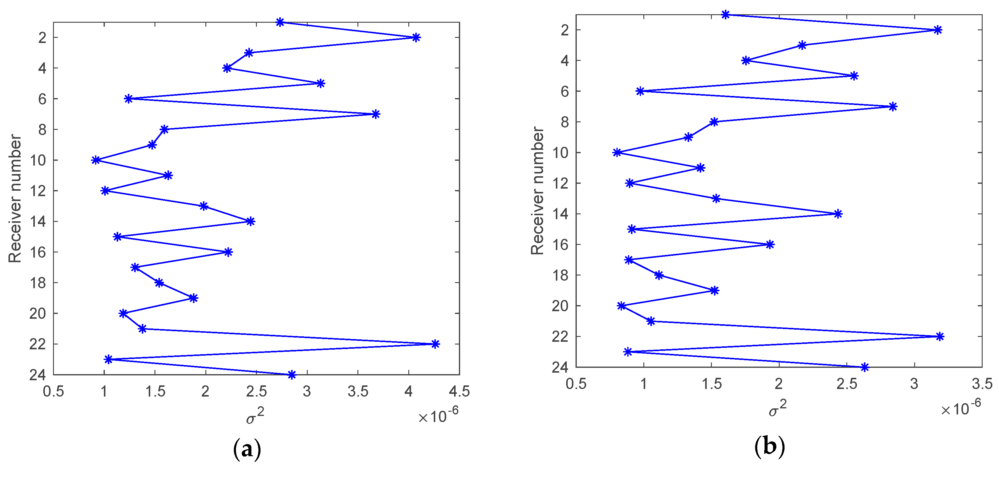
It can be considered that during the communication period, the noise power remains basically unchanged, so the data without information signal is intercepted, and its variance is calculated as the estimate of the noise power. The received noise power of the VRA is illustrated in Figure 5, where Figure 5a,b are the received noise power calculated from the data of 50 km and 80 km communications respectively. The received noise power measured in the two communications varies with the depth of the receivers, but the variation trends are basically the same due to the constant position of the VRA.
Since the SNR and noise power of the TR output signals of each array element are different, the spatial focusing gain of EGC is not the best. This paper proposes combining the TR output signals using the MRC method. Figure 6 illustrates the weight coefficients of TR-MRC calculated using different methods. Obviously, the weight coefficients calculated by the method proposed in this paper are basically consistent with those calculated by the conventional method, and those weight coefficients have a reciprocal relationship with the received noise power illustrated in Figure 5, indicating that the TR-MRC weight coefficients are only related to the received noise power of each array element while having nothing to do with the multipath. This verifies the correctness of the derivation of the TR-MRC weight coefficients, which means that the proposed method can be applied to TR communications.
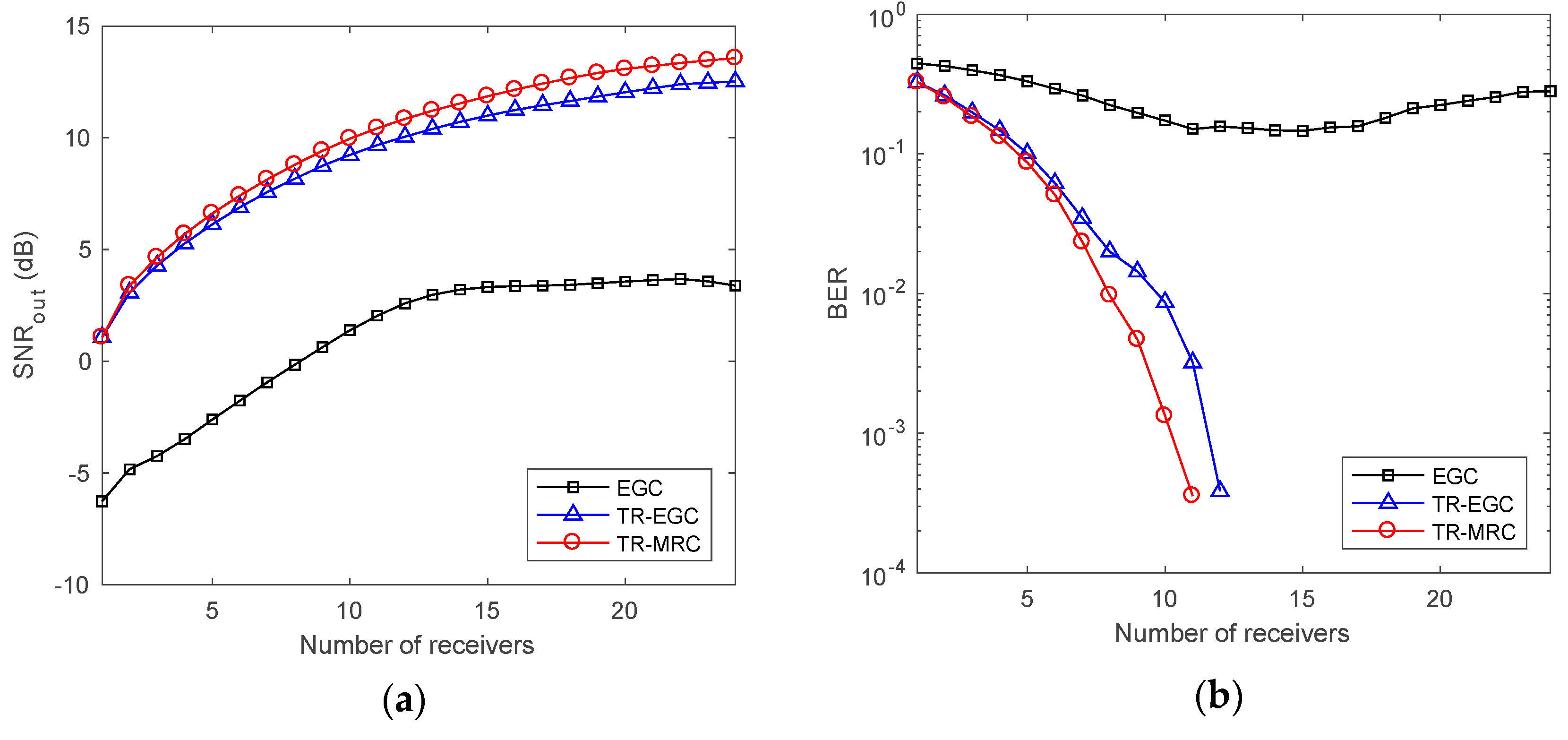
Figure 7 and Figure 8 show the performance of different TR combining approaches in the 50 km and 80 km UWA communications respectively. The output SNR and BER displayed in the figures are the mean values of the output results of the vertical arrays composed of adjacent elements at different depths. Figure 7a and Figure 8a show the output SNR of the VRA as a function of the number of receiver elements. It can be observed that TR processing significantly improves the output SNR of the VRA, and the output SNR gradually increases with the number of receivers, but the increasing speed gradually slows down. In addition, the output SNR of TR-MRC proposed in this paper is higher than that of the conventional TR-EGC. Figure 7b and Figure 8b show the communication BER as a function of the number of receivers. We can see that the BER is very high without using TR processing, while it rapidly decreases after TR processing, and the BER of TR-MRC decreases faster than the conventional TR-EGC. The results of the two communications indicate that the performance of TR-MRC is better than that of the conventional TR-EGC.
4. Conclusions
UWA channels are characterized by significant multipath, which leads to ISI and degrades the communication performance. TR has temporal and spatial focusing capability, where temporal focusing reduces the ISI, while spatial focusing mitigates channel fading and achieves a high SNR. This capability makes TR useful in UWA communications, especially in an undersea environment with significant multipath. Conventional TR is achieved by combining the single element TR outputs using the EGC method. Nevertheless, in the actual ocean environment, the SNR and noise power of the TR outputs of each array element are different, which makes the EGC method not the best choice. Therefore, this paper proposes using the TR-MRC method, which combines the TR output signals using the MRC method. The TR-MRC weight coefficients are theoretically deduced, and the deduction result indicates that the weight coefficients are only related to the received noise power of each array element and have nothing to do with the channel multipath structure, which means that the proposed method is simple and practical in TR communications. In January 2015, a long-range PDS communications experiment using a VRA was conducted in the South China Sea. The data rate was 50 bit/s with a 300 Hz bandwidth, and the communication distance was 50 km and 80 km respectively. The data processing results show that the TR-MRC weight coefficients calculated by the proposed method are consistent with those calculated by the conventional method, verifying the correctness of the weight coefficients derived in this paper. In addition, experimental results illustrate that the performance of TR-MRC is better than the conventional TR-EGC in terms of output SNR and BER, demonstrating the reliability of TR-MRC in UWA communications. As we all know, when there is relative motion between the transmitting end and the receiving end, the UWA channel changes rapidly, which will seriously degrade the communication performance. Therefore, next we will study the application of the proposed method in mobile TR communications.
Author Contributions
Conceptualization and methodology, A.Z. and C.Z.; validation, A.Z. and J.H.; formal analysis, C.Z. and K.W.; investigation, A.Z. and C.Z.; data curation, K.T.; writing—original draft preparation, review and editing, C.Z.; supervision and project administration, A.Z.; funding acquisition, A.Z. and J.H. All authors have read and agreed to the published version of the manuscript.
Funding
This research was funded by National Key Laboratory of Science and Technology on Underwater Acoustic Antagonizing (Grant No. SSDKKFJJ20180202), Science and Technology on Sonar Laboratory (Grant No. 614210902011906), and Acoustic Science and Technology Laboratory (Grant No. SSJSWDZC2020).
Institutional Review Board Statement
Not applicable.
Informed Consent Statement
Not applicable.
Data Availability Statement
The data presented in this study are available on request from the corresponding author.
Conflicts of Interest
The authors declare no conflict of interest.
References
- Song, H.C.; Hodgkiss, W.S.; Kuperman, W.A.; Stevenson, M.; Akal, T. Improvement of time-reversal communications using adaptive channel equalizers. IEEE J. Ocean. Eng. 2006, 31, 487–496. [Google Scholar] [CrossRef] [Green Version]
- Song, H.C. An overview of underwater time-reversal communication. IEEE J. Ocean. Eng. 2016, 41, 644–655. [Google Scholar] [CrossRef]
- Yang, T.C. Temporal resolutions of time-reversed and passive-phase conjugation for underwater acoustic communications. IEEE J. Ocean. Eng. 2003, 28, 229–245. [Google Scholar] [CrossRef]
- Edelmann, G.F.; Akal, T.; Hodgkiss, W.S.; Kim, S.; Kuperman, W.A.; Song, H.C. An initial demonstration of underwater acoustic communication using time reversal. IEEE J. Ocean. Eng. 2002, 27, 602–609. [Google Scholar] [CrossRef] [Green Version]
- Edelmann, G.F.; Song, H.C.; Kim, S.; Hodgkiss, W.S.; Kuperman, W.A.; Akal, T. Underwater acoustic communication using time reversal. IEEE J. Ocean. Eng. 2005, 30, 852–864. [Google Scholar] [CrossRef]
- Song, H.C.; Roux, P.; Hodgkiss, W.S.; Kuperman, W.A.; Akal, T.; Stevenson, M. Multiple-input-multiple-output coherent time reversal communications in a shallow water acoustic channel. IEEE J. Ocean. Eng. 2006, 31, 170–178. [Google Scholar] [CrossRef]
- Han, X.; Yin, J.W.; Du, P.Y.; Zhang, X. Experimental demonstration of underwater acoustic communication using bionic signals. Appl. Acoust. 2014, 78, 7–10. [Google Scholar] [CrossRef]
- Luan, Y.F.; Yan, S.F.; Qin, Y.; Xu, L.J. Doppler Estimation Using Time Reversal Mirror for Underwater Acoustic Time-varying Multipath Channel. In Proceedings of the 2017 IEEE International Conference on Signal Processing, Communications and Computing (ICSPCC), Xiamen, China, 22–25 October 2017. [Google Scholar] [CrossRef]
- Rouseff, D.; Jackson, D.R.; Fox, W.L.J.; Jones, C.D.; Ritcey, J.A.; Dowling, D.R. Underwater acoustic communication by passive-phase conjugation: Theory and experimental results. IEEE J. Ocean. Eng. 2001, 26, 821–831. [Google Scholar] [CrossRef]
- Yang, T.C. Differences between passive-phase conjugation and decision-feedback equalizaer for underwater acoustic communications. IEEE J. Ocean. Eng. 2004, 29, 472–487. [Google Scholar] [CrossRef]
- Shimura, T.; Ochi, H.; Song, H.C. Experimental demonstration of multiuser communication in deep water using time reversal. J. Acoust. Soc. Am. 2013, 134, 3223–3229. [Google Scholar] [CrossRef] [PubMed] [Green Version]
- Dowling, D.R. Acoustic pulse compression using passive phase-conjugate processing. J. Acoust. Soc. Am. 1994, 95, 1450–1458. [Google Scholar] [CrossRef]
- Song, H.C.; Hodgkiss, W.S.; Kuperman, W.A.; Higley, W.J.; Raghukumar, K.; Akal, T.; Stevenson, M. Spatial diversity in passive time reversal communications. J. Acoust. Soc. Am. 2006, 120, 2067–2076. [Google Scholar] [CrossRef] [Green Version]
- Song, H.C. Time reversal communication with a mobile source. J. Acoust. Soc. Am. 2013, 134, 2623–2626. [Google Scholar] [CrossRef] [PubMed]
- Song, H.C.; Hodgkiss, W.S. Self-synchronization and spatial diversity of passive time reversal communication. J. Acoust. Soc. Am. 2015, 137, 2974–2977. [Google Scholar] [CrossRef] [PubMed]
- Yang, T.C. Correlation-based decision-feedback equalizer for underwater acoustic communications. IEEE J. Ocean. Eng. 2005, 30, 865–880. [Google Scholar] [CrossRef]
- Brennan, D.G. Linear diversity combining techniques. Proc. IRE 1959, 47, 1075–1102. [Google Scholar] [CrossRef]
- Hu, S.Q.; Zhou, T.H.; Chen, W.B. Performance analysis and simulation of maximum ratio combining in underwater laser communication. Chin. J. Lasers 2016, 43, 1206003. [Google Scholar] [CrossRef]
- Hui, J.Y.; Liu, L.; Feng, H.H.; Liu, H. A study on pattern time delay shift coding underwater acoustic communication. Chin. J. Acoust. 1999, 18, 105–120. [Google Scholar] [CrossRef]
- Zhao, A.B.; Zeng, C.G.; Hui, J.; Ma, L.; Bi, X.J. Experimental Demonstration of Long-Range Underwater Acoustic Communication Using a Vertical Sensor Array. Sensors 2017, 17, 1516. [Google Scholar] [CrossRef] [PubMed] [Green Version]
- Yin, J.W.; Yang, S.; Yao, D.D.; Zhang, X. Study of underwater acoustic communication based on vector pattern time delay shift coding. In Proceedings of the OCEANS 2010 MTS/IEEE SEATTLE, Seattle, WA, USA, 20–23 September 2010. [Google Scholar] [CrossRef]
Figure 1.
Block diagram of TR combining.

Figure 2.
The sound speed profiles measured during the experiment along with the depth coverage of the VRA and the depths of the probe source.
Figure 2.
The sound speed profiles measured during the experiment along with the depth coverage of the VRA and the depths of the probe source.

Figure 3.
The channel responses received by the VRA from the PS at 40 m depth and 50 km range. (a) Before TR processing; (b) After TR processing.
Figure 3.
The channel responses received by the VRA from the PS at 40 m depth and 50 km range. (a) Before TR processing; (b) After TR processing.

Figure 4.
Performance of single element TR processing: input SNR, output SNR and temporal focusing gain. (a) 50 km UWA communication; (b) 80 km UWA communication.
Figure 4.
Performance of single element TR processing: input SNR, output SNR and temporal focusing gain. (a) 50 km UWA communication; (b) 80 km UWA communication.

Figure 5.
The received noise power of each array element. (a) 50 km UWA communication; (b) 80 km UWA communication.
Figure 5.
The received noise power of each array element. (a) 50 km UWA communication; (b) 80 km UWA communication.

Figure 6.
The TR-MRC weight coefficients calculated using different methods. (a) 50 km UWA communication; (b) 80 km UWA communication.
Figure 6.
The TR-MRC weight coefficients calculated using different methods. (a) 50 km UWA communication; (b) 80 km UWA communication.

Figure 7.
Performance of 50 km UWA communication as a function of the number of receivers. (a) Output SNR; (b) BER. Note: EGC means using EGC without TR processing.
Figure 7.
Performance of 50 km UWA communication as a function of the number of receivers. (a) Output SNR; (b) BER. Note: EGC means using EGC without TR processing.

Figure 8.
Performance of 80 km UWA communication as a function of the number of receivers. (a) Output SNR; (b) BER.
Figure 8.
Performance of 80 km UWA communication as a function of the number of receivers. (a) Output SNR; (b) BER.

Publisher’s Note: MDPI stays neutral with regard to jurisdictional claims in published maps and institutional affiliations. |
© 2021 by the authors. Licensee MDPI, Basel, Switzerland. This article is an open access article distributed under the terms and conditions of the Creative Commons Attribution (CC BY) license (http://creativecommons.org/licenses/by/4.0/).
Share and Cite
MDPI and ACS Style
Zhao, A.; Zeng, C.; Hui, J.; Wang, K.; Tang, K. Study on Time Reversal Maximum Ratio Combining in Underwater Acoustic Communications. Appl. Sci. 2021, 11, 1509. https://0-doi-org.brum.beds.ac.uk/10.3390/app11041509
AMA Style
Zhao A, Zeng C, Hui J, Wang K, Tang K. Study on Time Reversal Maximum Ratio Combining in Underwater Acoustic Communications. Applied Sciences. 2021; 11(4):1509. https://0-doi-org.brum.beds.ac.uk/10.3390/app11041509
Chicago/Turabian StyleZhao, Anbang, Caigao Zeng, Juan Hui, Keren Wang, and Kaiyu Tang. 2021. "Study on Time Reversal Maximum Ratio Combining in Underwater Acoustic Communications" Applied Sciences 11, no. 4: 1509. https://0-doi-org.brum.beds.ac.uk/10.3390/app11041509
Note that from the first issue of 2016, this journal uses article numbers instead of page numbers. See further details here.