Article

Entropy Generation and MHD Convection within an Inclined Trapezoidal Heated by Triangular Fin and Filled by a Variable Porous Media

1
Mechanical and Maintenance Engineering Department, School of Applied Technical Sciences, German Jordanian University, Amman 11180, Jordan
2
Mathematics Department, Faculty of Science, Northern Border University, Arar 73222, Saudi Arabia
3
Department of Mathematics, Faculty of Science, King Khalid University, Abha 62529, Saudi Arabia
*
Author to whom correspondence should be addressed.
Submission received: 12 December 2020 / Revised: 13 February 2021 / Accepted: 16 February 2021 / Published: 23 February 2021
(This article belongs to the Special Issue Nanofluids Application in Heat Transfer)

Abstract

:
Analyses of the entropy of a thermal system that consists of an inclined trapezoidal geometry heated by a triangular fin are performed. The domain is filled by variable porosity and permeability porous materials and the working mixture is Al2O3-Cu hybrid nanofluids. The porosity is varied exponentially with the smallest distance to the nearest wall and the permeability is depending on the particle diameter. Because of using the two energy equations model (LTNEM), sources of the entropy are entropy due to the transfer of heat of the fluid phase, entropy due to the fluid friction and entropy due to the porous phase transfer of heat. A computational domain with new coordinates (ξ,η) is created and Finite Volume Method (FVM) in case of the non-orthogonal grids is used to solve the resulting system. Various simulations for different values of the inclination angle, Hartmann number and alumina-copper concentration are carried out and the outcomes are presented in terms of streamlines, temperature, fluid friction entropy and Bejan number. It is remarkable that the increase in the inclination angle causes a diminishing of the heat transfer rate. Additionally, the irreversibility due to the temperature gradients is dominant near the heated fins, regardless of the values of the Hartmann number.

1. Introduction

Various industrial applications depend on the properties and nature of porous media. Thermal insulation, grain stocking and drying processes, the petroleum reservoir, compacted beds for the chemical industry and geophysical systems are good examples of these applications. This importance of these materials makes researchers focus on understanding their nature and properties [1,2,3,4,5]. In fact, the first category of porous medium investigations is concerned with situations where the properties (porosity, permeability and thermal conductivity) of the medium are constants [6,7,8,9,10]. Moreover, the presence of nanoparticles inside a thermal application solvent is receiving increasing attention as it allows one to control the performance in terms of heat transfer and entropy [11,12,13]. Therefore, researchers are targeting the analysis of situations where the two (porous materials and nanofluids) interact. Recent trends of such studies can be found in Ahmed [14] who discussed nanofluids motion in an inclined geometry filled with anisotropic porous elements. His outcomes mentioned that an increase in nanoparticles concentration by 4% results in an enhancement of the maximum temperature of the liquid by 12.27%. A porous medium with constant properties was considered by Rashed et al. [15] as a flow medium within a rectangular domain filled by nanofluids. The thermal dispersion impacts are of interest in this study. Their findings refer to a support in the values of the Nusselt (Nu) coefficient given as the Brownian parameter is growing. The two-energy model (LTNEM) in case of the constants porosity and permeability is used by Ahmed [16] to survey non-Darcy flow within trapezoidal geometries. The flow is due to the presence of a triangular fin that is located at the bottom. The domain is divided into nanofluid layer and porous layer. The outcomes uncovered that variations of the Neild number from 1 to 1000 results in an enhancement in the Nu coefficient by 95.6% at the value of the thermal conductivity ratio K r = 0.1 . The second category of porous media studies is focused on the variable properties of the medium, i.e., variable porosity, variable permeability and variable thermal conductivity. Examples of these studies are those of Al-Weheibi et al. [17], Abelman et al. [18], Saif et al. [19], Nithiarasu et al. [20], EL-Kabeir et al. [21] and Amiri and Vafai [22]. In all the mentioned studies, the porosity is varied exponentially with the smallest distance to the nearest wall and the permeability depends on the particle diameter.
On the other side, the dynamical behaviors of nanofluids within irregular geometries (trapezoidal, triangle, wavy, etc.) have been examined by various investigators in recent years. Treatments of such domains may be made using the body-fitted method, i.e., converting the complex real physical model into a rectangular computational model. While cavities with regular shapes and fins have been studied extensively in many research works, such as [23,24,25], non-regular geometries have received less focus and the aforementioned method is effective in simulations of the transfer of heat problems concerning them. The real coordinates ( x , y ) are expressed as functions in new coordinates ( ξ , η ) , and based on these functions, all the partial derivatives of the dependent variables are transformed into the new coordinates [26,27]. Alsabery et al. [28] used a trapezoidal geometry as a flow domain to discuss the transfer of heat by Darcian nanofluid flow. They considered that the domain is inclined and divided into two layers (porous layer and nanofluid layer). They noted a remarkable enhancement in the rate of heat transfer in the case of silver–water mixture. Alsabery et al. [29] discussed a trapezoidal domain that is divided into nanofluid porous layer and non-Newtonian fluid layer. Visualization of the heat lines within the system is of interest. Their results reveal that for fixed values of the power-law index (n = 0.7), activity of the mixture flow is enhanced as the Prandtl number grows. Nanofluids flow within triangular domains heated from inside/outside (two heating modes) is examined by Ahmed et al. [30]. The geometry is filled by copper as nanoparticles and includes heated/cooled fins with a variable length. The outcomes disclose that the boost in the height of the fins augments the transfer of heat rate. Additionally, these irregular geometries with various thermal conditions have been handled by different scientific researchers [31,32,33,34,35]: particularly, magneto-convective flow of nanofluids confined open trapezoidal enclosures by Miroshnichenko et al. [36] and Astanina et al. [37]. Finally, it should be noted that many research articles that deal with different shapes and geometries along with many different nanofluids and hybrid nanofluids for conventional fluids or rarefied gases under the influence of many parameters can be found in [38,39,40,41,42].
As stated previously, using triangular fins within the containers as controlling factors for the nanofluids flows and the variable properties of the porous medium have not been considered widely. Thus, the main objective of this simulation is to study the magnetohydrodynamic hybrid nanofluid flow in trapezoidal containers heated by triangular fins. Unusually, the magnetic field is in a horizontal direction while the flow domain is inclined. The properties of the porous medium, namely, the porosity and permeability, as well as values of the Da, are considered as variables. Entropy analyses in the case of the two-energy model (LTNEM) are examined. The real physical domain is transformed to a rectangular computational domain, then the finite volume method based on non-orthogonal grids is applied to solve the resulting system. The novelty significance of the current study appears in the following points:
  • Using an irregular flow domain heated by irregular fin that was not presented before.
  • Properties of the porous medium are considered variables and this assumption makes the work more attractive to readers.
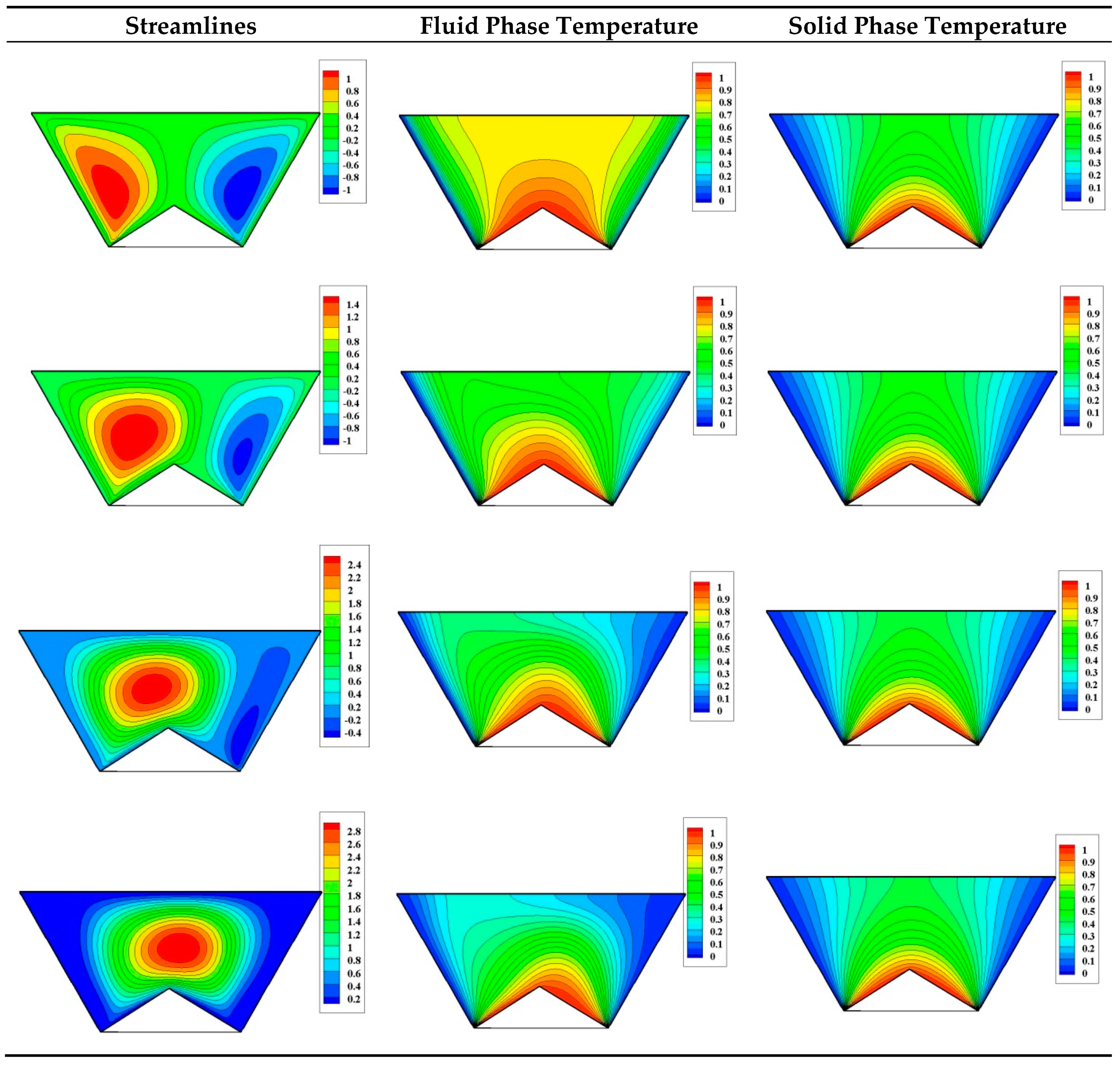
  • Physically, the local thermal non-equilibrium state (two-energy equations model) is more realistic than the local thermal equilibrium case.
  • Most of the published works in this field consider the magnetic field as inclined and the geometry as non-inclined, and hence, the formulation of the governing system when the magnetic force is horizontal and the geometry is inclined is unusual and novel.
  • Analyses of the second law of thermodynamics for such kinds of complex geometries (triangular fin within a trapezoidal enclosure) have not been presented before.
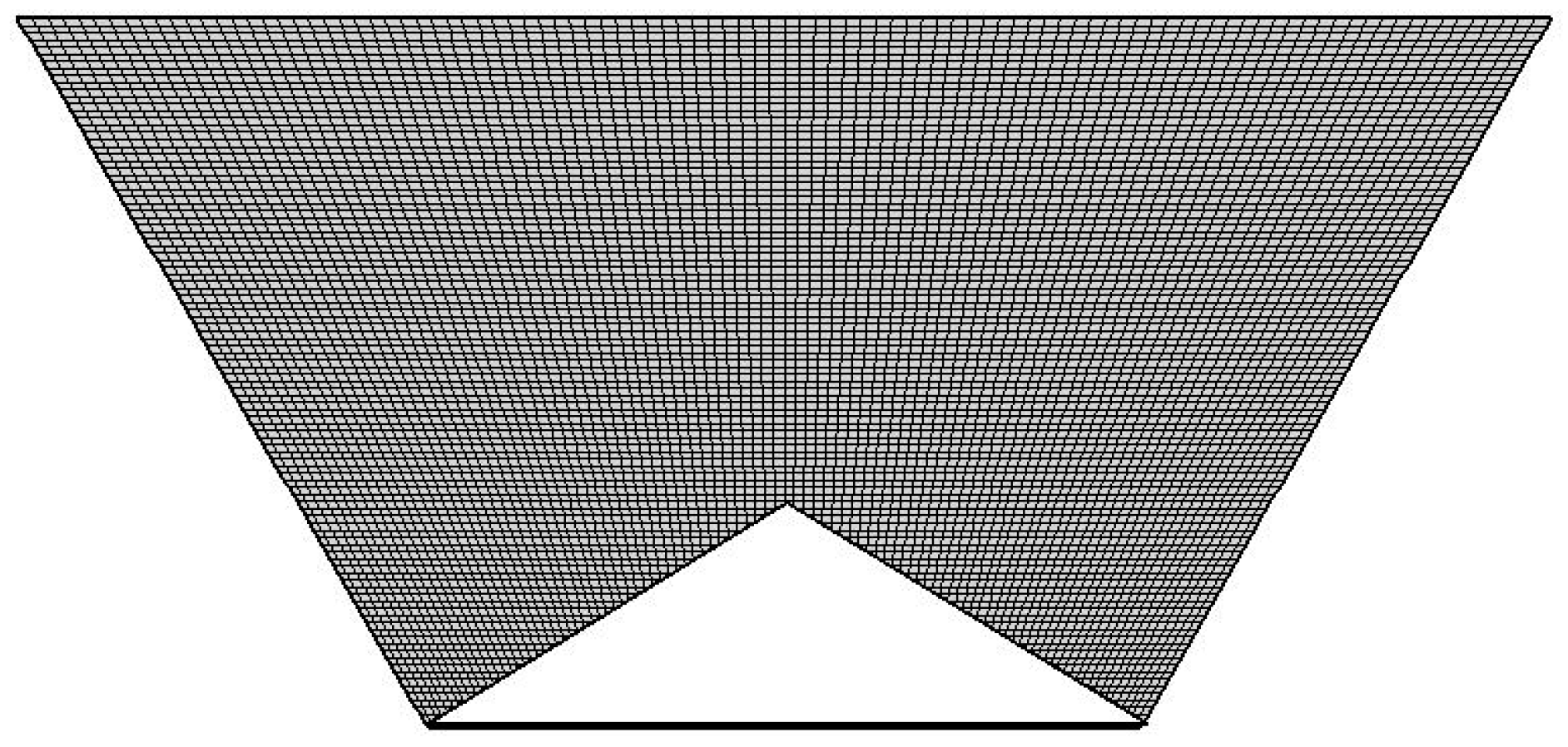
  • The numerical methodology which depends on mapping between the real–irregular domain and regular–rectangular computational domain has received less focus.
  • Finally, various practical applications for the current simulations can be found, e.g., air conditioning systems in buildings, furnace and home heating, electronic equipment cooling, drying foods and double pane windows.

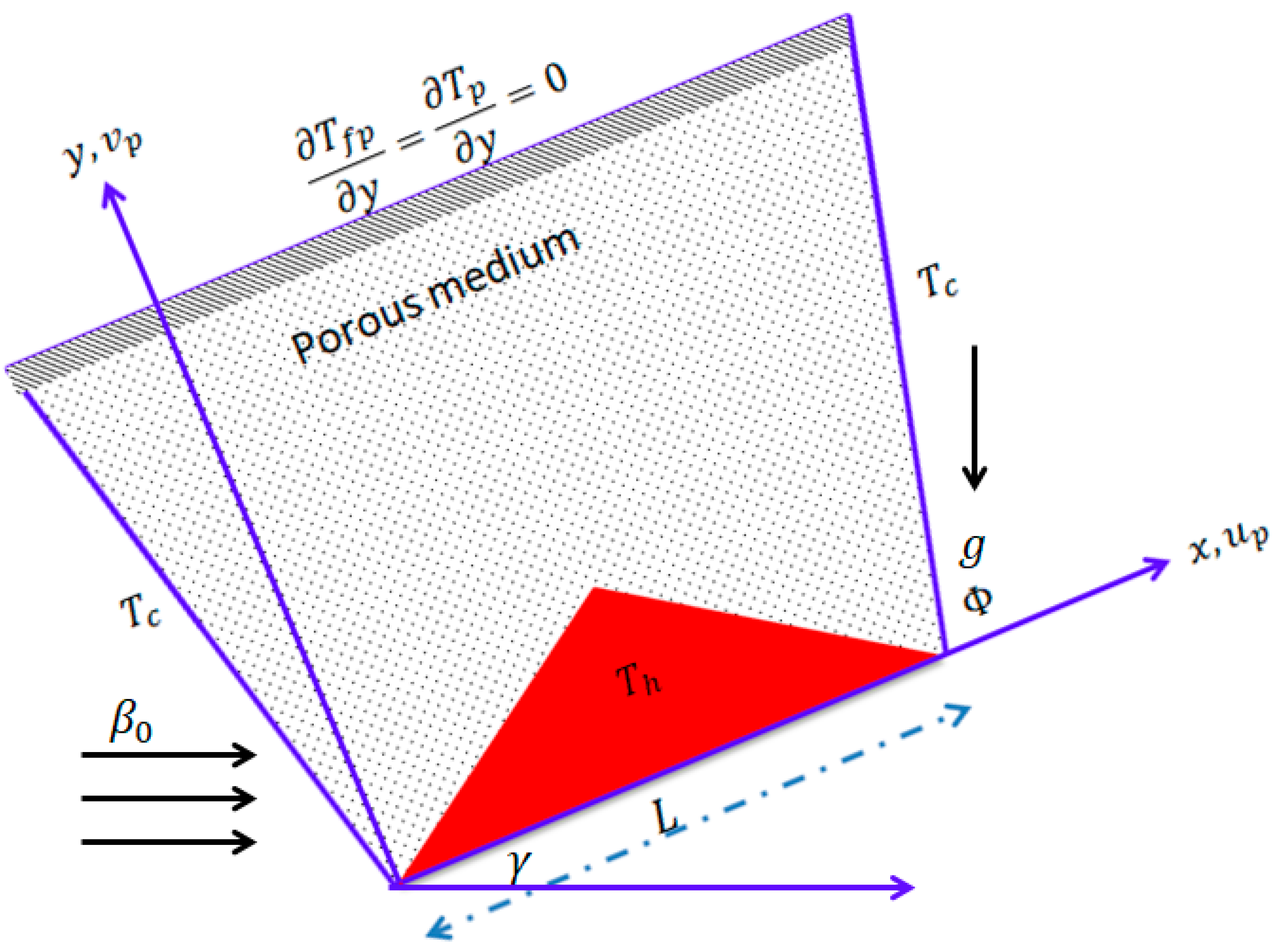
2. Formulation of the Problem

A horizontal magnetic field with strength β 0 is influencing on an inclined trapezoidal domain heated by a triangular fin, as illustrated in Figure 1. The inclined walls of the containers are referred to with a low temperature T c while the upper wall is insulated. The inclination angle is γ and the gravity and magnetic vectors are, respectively, ( g sin γ ,   g cos γ ) , ( β 0 cos γ ,   β 0 sin γ ) . The trapezoidal angle is Φ and the geometry is filled by a variable properties porous medium. The non-equilibrium thermal model between the hybrid nanofluid and porous phases is valid. The mixture consists of alumina and copper nanoparticles suspended in a base fluid (water). Properties of the nanoparticles and water are given in Table 1. In addition, the porous elements are considered as a compacted spheres bed. Therefore, the model proposed by Ergun [43] for permeability is introduced. One of the features of this model is that the permeability depends on the particle size (particle diameter d p ) and the porosity of the medium ε . It is expressed as:
K = d p 2 ε 3 150 ( 1 ε ) 2
In addition, the variable porosity of the medium is taken as a function of the particle size d p and the smallest distance to the nearest wall | y | . This relation is given as:
( y ) = ε ( 1 + a 1 exp [ a 2 | y | d p ] )
Values of the empirical constants a 1 and a 2 are introduced by Cheng and Hsu [44] as 1.4 and 5, respectively, and the value of ε is considered as 0.36. Using this correlation, the porosity near the bottom wall is equal to 0.864 and this value decreases exponentially as the distance from the bottom wall is increased. The D a is also considered a variable in this study.
                            D a ( y ) = K ( y ) L 2 = d p 2 ε 3 150 ( 1 ε ) 2 1 L 2
When all these assumptions are taken into account, the two-energy model governing this physical case is given as:
u p x + v p y = 0
ρ h n f ε u p t + ρ h n f ε [ u p ( u p ε ) x + v p ( u p ε ) y ] = p x + μ e f f ε ( 2 u p x 2 + 2 u p y 2 ) μ e f f K u p C F ρ h n f K u p 2 + v p 2 u p + ( ρ β ) h n f ( T f p T c ) g sin γ σ h n f β 0 2 ε ( v p sin γ cos γ + u p sin 2 γ )
ρ h n f ε v p t + ρ h n f ε   [ u p ( v p ε ) x + v p ( v p ε ) y ] = p y + μ e f f ε ( 2 v p x 2 + 2 v p y 2 ) μ e f f K v p C F ρ h n f K u p 2 + v p 2   v p + ( ρ β ) h n f ( T f p T c ) g cos γ σ h n f β 0 2 ε ( u p sin γ cos γ + v p cos 2 γ )
ε ( ρ c p ) h n f T f p t + ( ρ c p ) h n f ( u p T f p x + v p T f p y ) = ε k h n f ( 2 T f p x 2 + 2 T f p y 2 ) + h ( T p T f p )
( 1 ε ) ( ρ c p ) p T p t = ( 1 ε ) k p ( 2 T p x 2 + 2 T p y 2 ) + h ( T f p T p )
The symbols in Equations (4)–(8) are the velocity fields u p , v p , the temperature for the hybrid nanofluid/solid phase T f p , T p , the porosity ε , the permeability K , the electrical conductivity σ h n f , the thermal conductivity k h n f , the independent variables (Cartesian coordinates and time) x , y ,   t and the gravity acceleration g . In addition, the following dimensionless quantities are submitted:
( U p , V p ) = ( u p ,   v p ) L α f ,   ( θ f p ,   θ p ) = (   T f p ,   T p ) T c Δ T ,   Δ T = (   T f p ,   T p ) h T c ) , ( X L , Y L ) = ( x , y )   ,   P = L 2 ρ n f   α f 2 p ,     τ = α f L 2   t
Substituting Equation (9) into Equations (4)–(8), the following combined dimensionless system is given:
U p X + V p Y = 0
1 ε U p τ + 1 ε   [ U p ( U p ε ) X + V p ( U p ε ) Y ] = P X + P r 1 ε μ h n f μ f ρ f ρ h n f [ 2 U p X 2 + 2 U p Y 2 ] [ P r D a ( Y ) μ h n f μ f ρ f ρ h n f + C f D a ( Y ) U p 2 + V p 2 ] U p + R a P r ( ρ β ) h n f ( ρ β ) f   ρ f ρ h n f θ f p   s i n γ σ h n f σ f ε ρ f ρ h n f H a 2 P r ( V p sin γ cos γ + U p sin 2 γ )
1 ε V p τ + 1 ε 2 [ U p ( V p ε ) X + V p ( V p ε ) Y ] = P Y + P r 1 ε μ h n f μ f ρ f ρ h n f [ 2 V p X 2 + 2 V p Y 2 ] [ P r D a ( Y ) μ h n f μ f ρ f ρ h n f + C f D a ( Y ) U p 2 + V p 2 ] V p + R a P r ( ρ β ) h n f ( ρ β ) f ρ f ρ h n f θ f p cos γ σ h n f σ f ε ρ f ρ h n f H a 2 P r ( U p sin γ cos γ + V p cos 2 γ )
ε   θ f p τ + ( U p θ f p X + V p θ f p Y ) = ε [ α h n f α f ( 2 θ f p X 2 + 2 θ f p Y 2 ) + ( ρ c p ) f ( ρ c p ) h n f H ( θ p θ f p ) ]
( 1 ε ) θ p τ α r ( 1 ε ) [ ( 2 θ p X 2 + 2 θ p Y 2 ) + H K r ( θ f p θ p ) ] = 0
The subjected conditions to the boundaries of the geometry are:
τ 0 : Y = 0 ,   0 X 1 ,   U p = V p = 0 ,   θ f p Y = θ p Y = 0 τ 0 : Y = 1 ,   1 tan Φ X 1 + tan Φ ,   U p = V p = 0 ,   θ f p Y = θ p Y = 0 τ 0 : X + Y tan Φ = 0 ,   0 Y 1 ,   U p = V p = 0 ,   θ f p = θ p = 0 τ 0 : X Y tan Φ = 1 ,   0 Y 1 ,   U p = V p = 0 ,   θ f p = θ p = 0
On the inner fin:
θ f p = θ p = 1
In Equations (10)–(15), Pr = ν f α f is the Prandtl number, R a = β f   g   ( T h T c ) L 3 α f ν f is the Raleigh number, D a = K L 2 is the Darcy number, H = h L 2 ε   k f is the Nield number and K r = ε   k f   ( 1 ε ) k p is the thermal conductivity ratio.

2.1. Correlations of the Hybrid Nanofluids

Correlations of the hybrid nanofluids were presented recently by Ahmed [45]. Following this investigation, the density, heat capacitance, thermal expansion, thermal diffusivity, thermal conductivity, dynamic viscosity and electrical conductivity are, respectively:
ρ h n f = ϕ A l 2 O 3 ρ A l 2 O 3 + ϕ C u ρ C u + ( 1 ϕ ) ρ b f
( ρ C p ) h n f = ϕ A l 2 O 3 ( ρ C p ) A l 2 O 3 + ϕ C u ( ρ C p ) C u + ( 1 ϕ ) ( ρ C p ) b f
( ρ β ) h n f = ϕ A l 2 O 3 ( ρ β ) A l 2 O 3 + ϕ C u ( ρ β ) C u + ( 1 ϕ ) ( ρ β ) b f
α h n f = k h n f ( ρ C p ) h n f
k h n f k b f = ( ( ϕ A l 2 O 3 k A l 2 O 3 + ϕ C u k C u ) ϕ + 2 k b f + 2 ( ϕ A l 2 O 3 k A l 2 O 3 + ϕ C u k C u ) 2 ϕ k b f ) × ( ( ϕ A l 2 O 3 k A l 2 O 3 + ϕ C u k C u ) ϕ + 2 k b f ( ϕ A l 2 O 3 k A l 2 O 3 + ϕ C u k C u ) + ϕ k b f ) 1
μ h n f = μ b f ( 1 ( φ A l 2 O 3 + φ C u ) ) 2.5
σ h n f σ b f = 1 + 3 ( ( φ A l 2 O 3 σ A l 2 O 3 + φ C u σ C u ) σ b f ( φ A l 2 O 3 + φ C u ) ) ( ( φ A l 2 O 3 σ A l 2 O 3 + φ C u σ C u ) φ σ b f + 2 ) ( ( φ A l 2 O 3 σ A l 2 O 3 + φ C u σ C u ) σ b f ( φ A l 2 O 3 + φ C u ) )

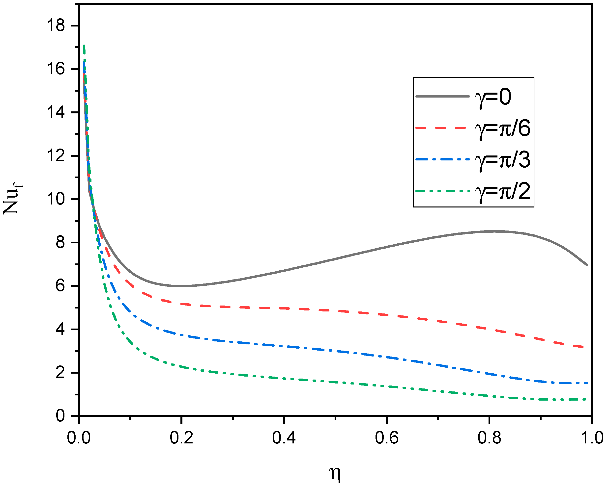
2.2. Heat Transfer Coefficient

The heat transfer rate is calculated at both the left and right walls. Since these walls are inclined, these quantities are given as:
For the fluid phase:
( N u f ) L = k h n f k f [ θ f p X sin Φ + θ f p Y cos Φ ]
( N u f ) R = k h n f k f [ θ f p X sin Φ + θ f p Y cos Φ ]
For the solid phase:
( N u s ) L = θ p X sin Φ + θ p Y cos Φ
( N u s ) R = θ p X sin Φ + θ p Y cos Φ

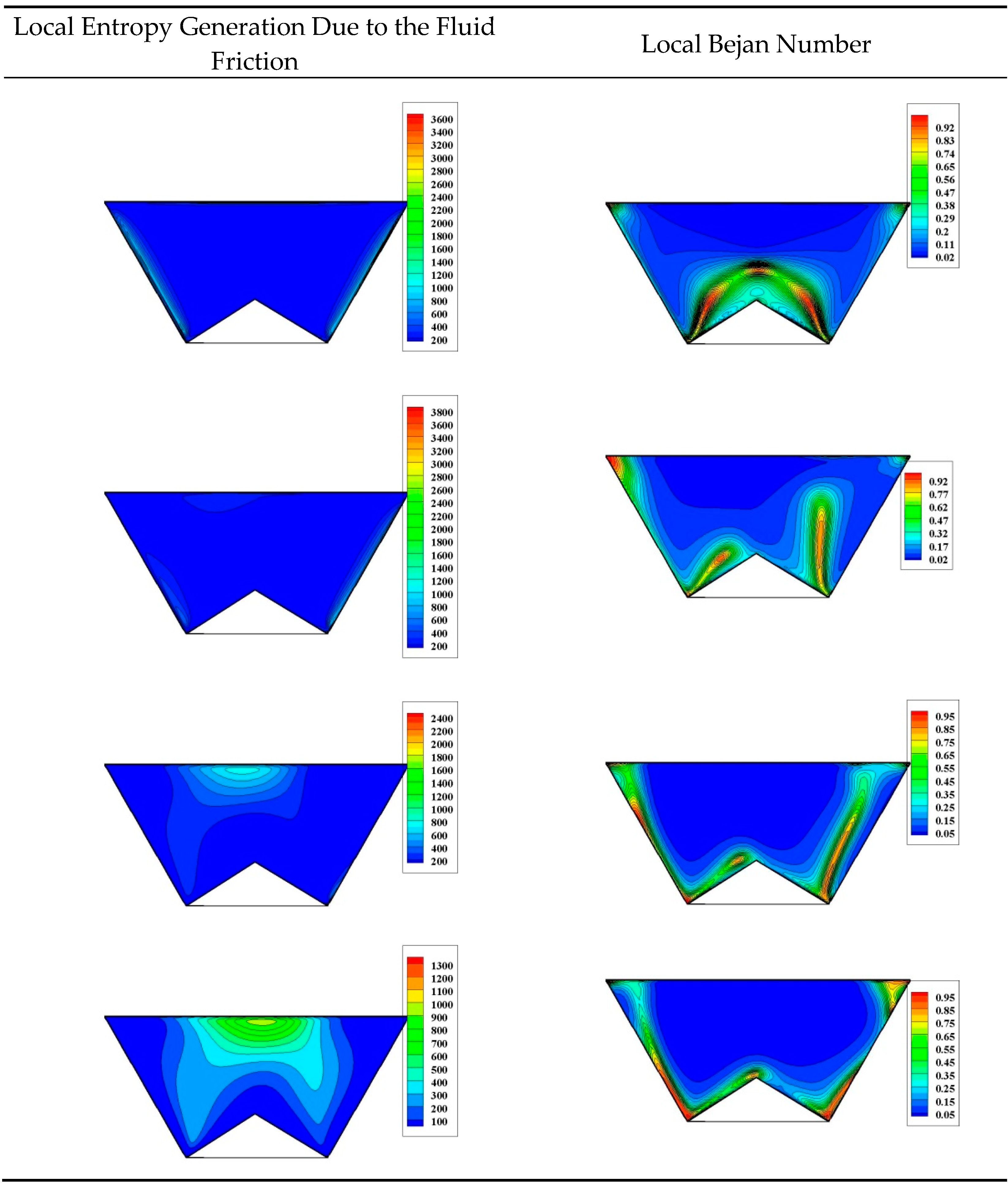
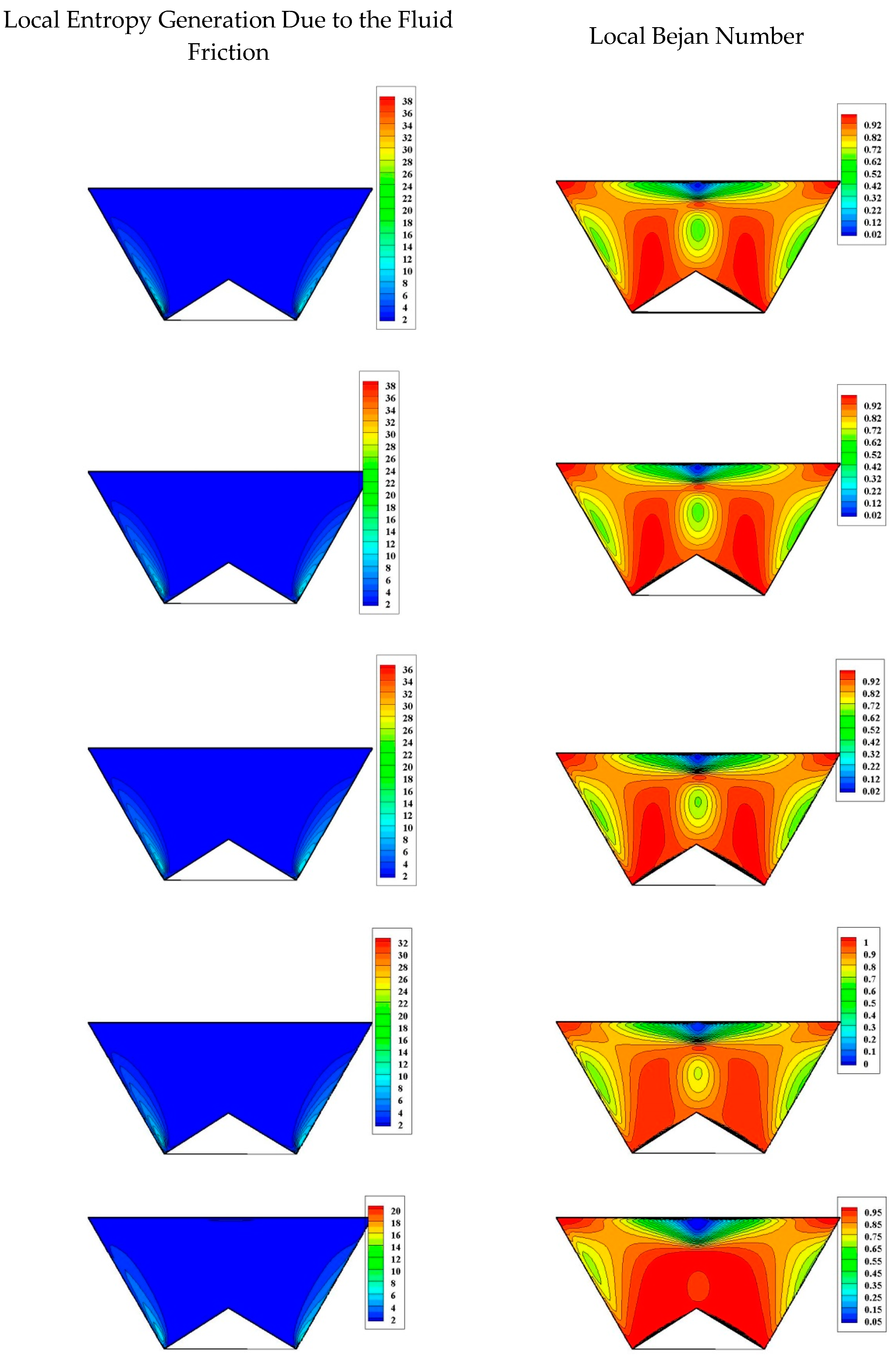
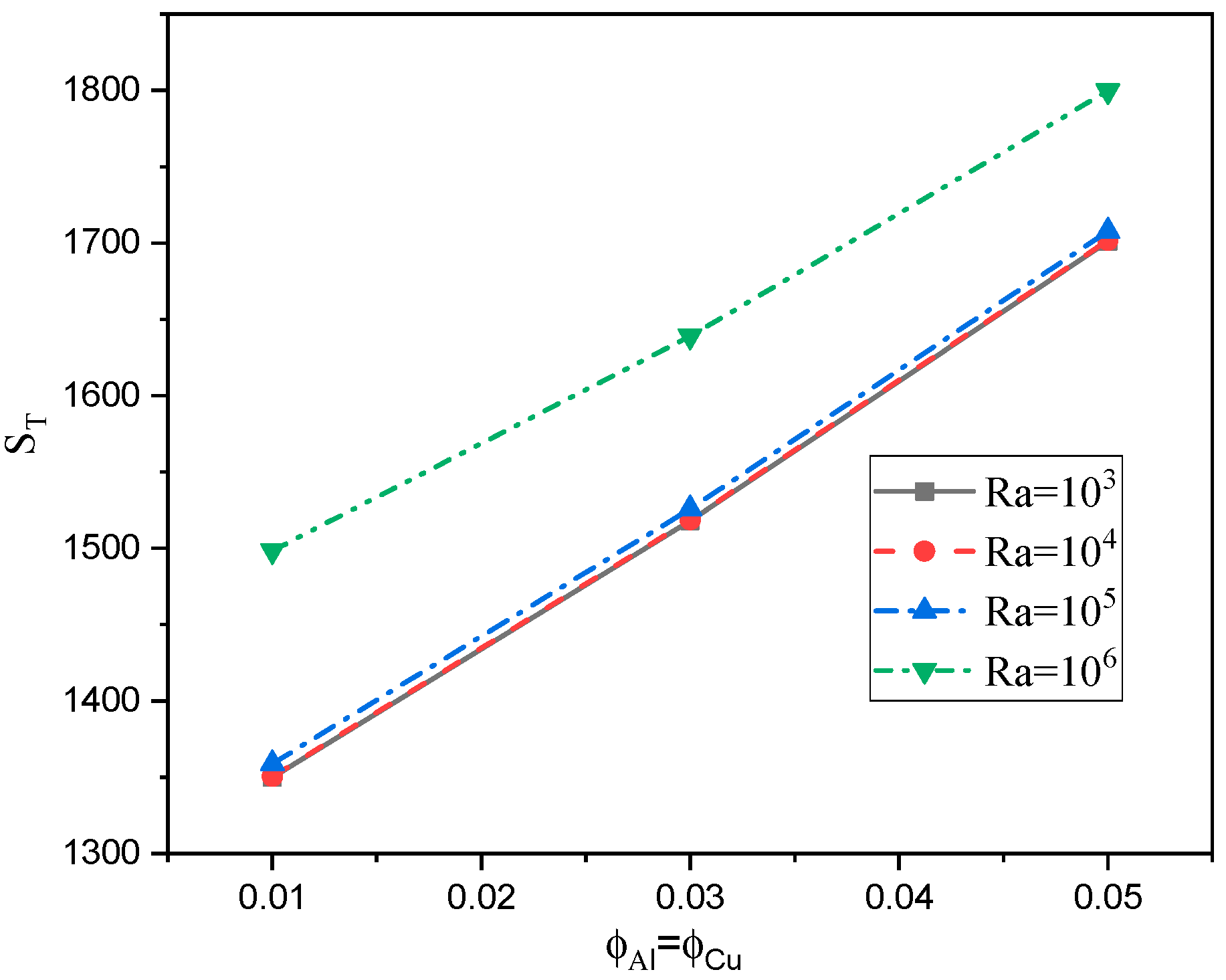
2.3. Entropy Generation Analysis

The entropy equations can be written in the following form:
s f = k h n f T 0 2 ( T f p ) 2 + μ h n f T 0   K ( y )   ( V V ) + μ h n f T 0 ( τ i j : V ) + σ h n f T 0 | V B | 2 + h ( T p T f p ) 2 T 0 2
s p = k p T 0 2 ( T p ) 2 + h ( T p T f p ) 2 T 0 2
where T 0 = T h + T c 2 , using the dimensionless variables and the characteristics of entropy
S 0 = k f ( Δ T ) 2 L 2 T 0 2 ) ,   S 0 p = k p ( Δ T ) 2 L 2 T 0 2
In the above equation, Θ = μ f T 0 k 0 ( α f H Δ T ) 2 is the ratio of the irreversibility distribution. In addition, the local and average Bejan number (Be) is expressed as:
Using the dimensionless quantities, the entropy generation is given as:
S f = k h n f k f [ ( θ f p X ) 2 + ( θ f p Y ) 2 ] + Θ μ h n f μ f [ 1 D a ( Y ) ( U p 2 + V p 2 ) + 2 ( U p X ) 2 + 2 ( V p Y ) 2 + ( U p Y + V p X ) 2 ] + Θ σ h n f σ f H a 2 ( U p sin γ V p cos γ ) 2 + ε H ( θ p θ f p ) 2
S p = [ ( θ p X ) 2 + ( θ p Y ) 2 ] + K r ( 1 ε ) H ( θ p θ f p ) 2
The total dimensionless entropy generation is the sum of these components (Buonomo et al. [46]), and it is written as:
S t o t a l = S f + S p
The entropy generation due to the entire domain can be obtained by integrating the previous component over the entire domain as:
S T = Ω   S T   d Ω
S f = Ω   S f   d Ω
S T s = Ω   S p   d Ω
S t o t a l   = Ω   S t o t a l   d Ω
The local Be is the ratio between the local entropy generation due to the transfer of heat (sum of the entropy generation due to the heat transfer for the fluid phase and for the solid phase) and the entropy generation due to the fluid friction; thus, it can be expressed as:
B e = k h n f k f [ ( θ f p X ) 2 + ( θ f p Y ) 2 ] + [ ( θ p X ) 2 + ( θ p Y ) 2 ] + H ( θ p θ f p ) 2 ( ε + K r ( 1 ε ) ) S t o t a l
Here, it should be mentioned that the ratio of the irreversibility distribution Θ is fixed at 10 4 for all the computations and this value is selected according to Ilis et al. [47].

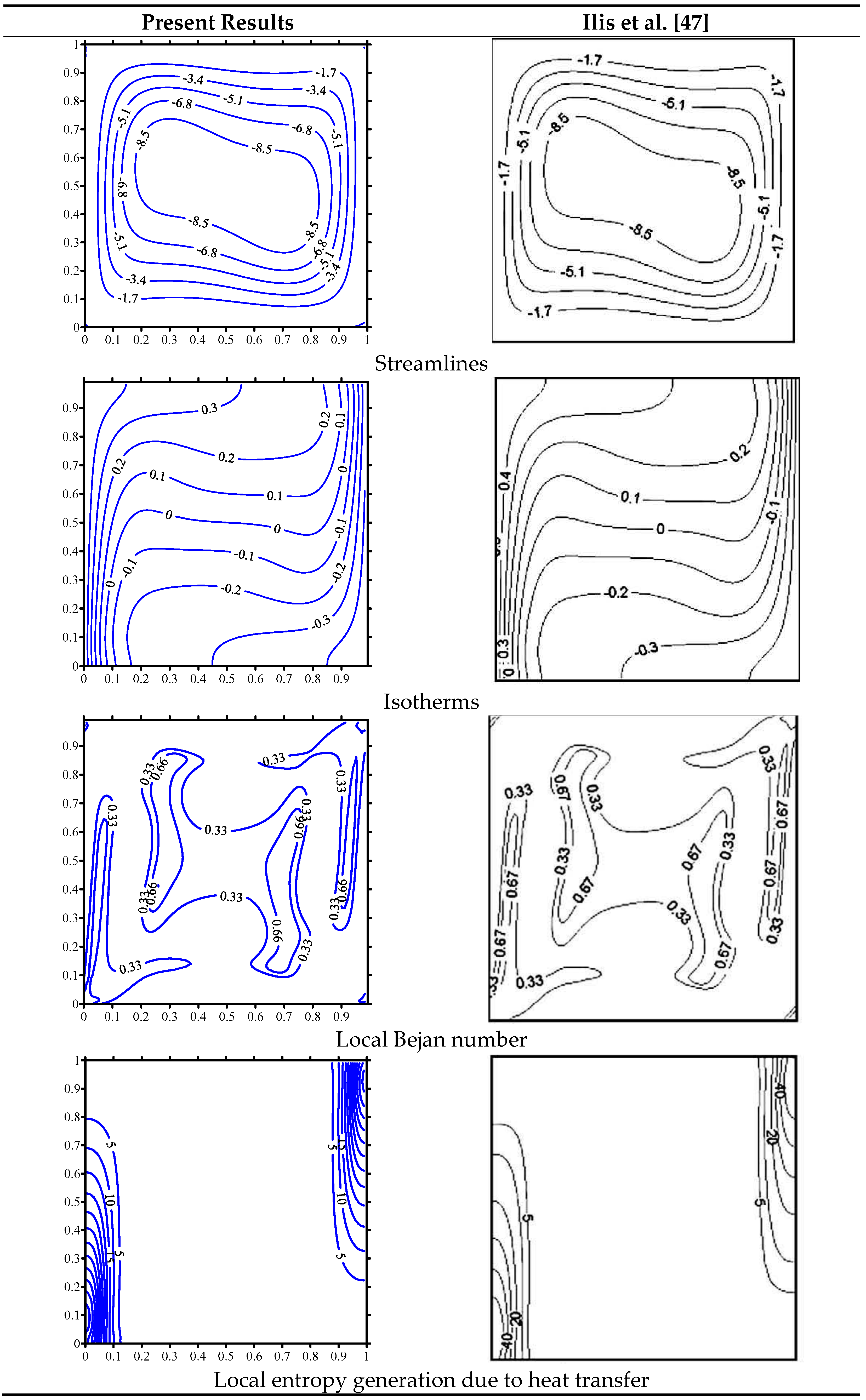
3. Numerical Treatments

The numerical treatments used to solve the governing equations are the non-orthogonal grids FVM. The real physical domain ( X , Y ) is converted to a rectangular domain ( ξ , η ) using the following functions:
ξ = X + Y cot Φ 1 + 2 Y cot Φ , η = Y A .
Using (32), the advection terms are given as:
( U Ω ) X + ( V Ω ) Y = 1 J * [ ξ ( Ω U * ) + η ( Ω V * ) ] ,
where
U * = β 11 U + β 21 V ,
V * = β 22 V + β 12 U ,
β 11 = Y η ,   β 12 = Y ξ ,
β 21 = X η ,   β 22 = X ξ .
Similar, the diffusive terms are expressed as:
X [ Γ * Ω X ] + Y [ Γ * Ω Y ] = 1 J * ξ [ Γ * α 11 Ω ζ + Γ * α 12 Ω η ] + 1 J * η [ Γ * α 22 Ω η + Γ * α 12 Ω ζ ]
In Equation (38), α 11 , α 22 are expressed as:
α 11 = α * J * = X η 2 + Y η 2 J * = β 21 2 + β 11 2 J * ,
α 22 = γ * J * = X ζ 2 + Y ζ 2 J * = β 12 2 + β 22 2 J * .
The upwind scheme is used to discretize the transformed convective terms while the diffusive terms are treated using the central differences scheme. The alternating direction implicit method (ADI) is introduced to solve the obtained algebraic system. The iterative technique is employed until the convergence criterion ( 10 6 ) is fullfiled. Additionally, after many grid tests being made (as it is presented in Table 2), the grid size 101 × 101 was found suitable for all computations. Further, Figure 2 shows the mesh used in all computations, which consists of 101 × 101 nodes.
Figure 3 illustrates a comparison between the current code results and the results obtained by Ilis et al. [47] for the case of a square cavity in which the left wall is kept at a hot temperature, the right wall is kept at a cold temperature while the lower and upper walls of the cavity are considered adiabatic. The comparison is implemented for the case where R a = 10 5 ,   P r = 0.71 , Θ = 10 4 . Contours for the streamlines, isotherms, local Bejan number and local entropy generation due to heat transfer are constructed. Comparison shows a very good agreement between contours resulted from the current code to those presented in Ilis et al. [47].

4. Discussion of Results

Figure 4 elucidates the streamlines and isotherms of the liquid phase and the isotherms of the porous phase for the cases where R a = 10 6 ,   H a = 15 ,   H = 0.1 ,   ϕ A l = ϕ C u = 1 % ,   Φ = π 3 and different inclination angles. As far as the streamlines are concerned, plots show a formation of two symmetric cells for an inclination angle of zero. The cell on the left hand side starts to dominate the region as the inclination angle increases. This is mainly due to the buoyancy forces. For the isotherms related to the fluid phase, plots show a formation of a hot thermal region near the fin. Moreover, plots show that for an inclination angle of zero, isotherms are symmetric throughout the centerline of the cavity with a maximum area covered by higher values of isotherms. As the angle increases, distortion of the isotherms happens as they shift counter clockwise. Additionally, it is obvious that as the inclination angle increases, less area of the domain is covered by higher values of the isotherms. Finally, the graph shows that for the porous phase, symmetric isotherms are observed for all inclination angles. Furthermore, as the inclination angle increases, the impact on the temperature distribution is very minimal as the porous temperature is not coupled with the velocity fields.
Figure 5 illustrates features of the local entropy generation due to the fluid friction and local B e for the variation of the inclination angle γ ( γ = 0 , π 6 , π 3 , π 2 ) at R a = 10 6 ,   H a = 15 ,   H = 0.1 ,   ϕ A l = ϕ C u = 1 % ,   Φ = π 3 . The graph shows that the Sf decreases as the γ increases. The local entropy generation for γ equals zero appears to have the maximum values near the side walls. As the γ increases, this maximum value takes place at the upper wall of the cavity. Moreover, the graph shows that for γ , B e less than 0.5 contours occupies most of the domain of the cavity; this is mainly due to the friction. Additionally, Be contours greater than 0.5 are observed at or near the sidewalls of the cavity as well as the fin walls. For these cases where B e is greater than 0.5, the entropy generation is mainly due to the transfer of heat.
Figure 6 represents features of the streamlines and temperature distribution for the fluid phase and porous phase for the variation of the Hartmann number H a ( H a = 0 , 15 , 25 , 50 , 100 ) at R a = 10 5 ,   H = 0.1 ,   ϕ A l = ϕ C u = 1 % ,   Φ = π 3 , γ = 0 . The graph shows a formation of two symmetric cells inside the cavity as far as the streamlines are concerned. The intensity of the streamlines decreases as H a increases. The magnetic field will suppress the flow and consequently lower values of the streamlines are observed by increasing H a . Moreover, the hot thermal regions are observed near the fin walls for both the fluid and porous temperature distributions. Finally, the graph shows a slight change in the temperature distributions with H a .
Figure 7 represents features of the local entropy generation due to the fluid friction and local Be for the variation of the Hartmann number H a ( H a = 0 , 15 , 25 , 50 , 100 ) at R a = 10 5 ,   H = 0.1 ,   ϕ A l = ϕ C u = 1 % ,   Φ = π 3 , γ = 0 . The graph shows that Sf decreases as H a increases. Moreover, it is noted from B e contours and for all cases of H a that the local entropy generation is dominated by the thermal component near the fin walls and at the corners of the cavity; while it is dominated by the friction at a small portion of the top wall of the cavity.
Variations of the local Nu for the cases where nanoparticle volume fraction ϕ A l = ϕ C u = 1 % at   H a = 15 ,   H = 0.1 ,   γ = π 6 ,   Φ = π 3 and different R a are plotted in Figure 8. The graph shows that as the γ decreases, Nu decreases. This is because as the angle increases, the thermal boundary layers near the inclined walls decrease. This will result in a reduction in the transfer of heat rate, and consequently, lower Nu is achieved.
Figure 9 presents profiles of the local Nu for the variation of the Ra and nanoparticle volume fraction ϕ A l = ϕ C u at   H a = 15 ,   H = 0.1 ,   γ = π / 6 ,   Φ = π 3 . The graph shows that as R a increases, the Nu increases. This is mainly due to the fact that as R a increases, the dominant mode of transfer of heat becomes convection, and consequently, higher Nu is given. Moreover, the graph shows that as the s   ϕ increases for the case of R a = 10 4 and R a = 10 5 , better Nu is achieved. As ϕ increases, better effective conductivity is achieved and consequently better transfer of heat. At R a = 10 6 , the activity of the hybrid nanofluids flow is much affected by the increase in ϕ A l , ϕ C u . In this case, the overall viscosity is augmented, and thus, the convective process and likewise the Nu are decreased.
In Figure 10, profiles of the entropy generation due to the transfer of heat of the hybrid nanofluid phase in the entire domain for the variation of the Ra and nanoparticle volume fraction ϕ A l = ϕ C u at   H a = 15 ,   H = 0.1 ,   γ = π 6 ,   Φ = π 3 are constructed. The graph shows that as R a increases, the ST increases. Moreover, the graph shows that as the ϕ increases, ST increases as well. Higher volume fraction is associated with better conductivity and hence a higher entropy generation due to heat is achieved.
Figure 11 shows profiles of the total entropy generation in the entire domain for the variation of the Ra and nanoparticle volume fraction ϕ A l = ϕ C u at   H a = 15 ,   H = 0.1 ,   γ = π / 6 ,   Φ = π 3 . The graph shows that the Stotal increases as Ra increases. Furthermore, the graph shows for the cases of R a = 10 4 and R a = 10 5 , as ϕ increases, the Stotal increases. Finally, the graph shows that for the case where R a = 10 6 , as the ϕ increases, the Stotal increases. This is mainly because the entropy generation due to the heat increases with the volume fraction while the entropy generation due to friction decreases.
Figure 12 illustrates profiles of the entropy generation due to the transfer of heat of the solid phase in the entire domain for the variation of the Ra and nanoparticle volume fraction ϕ A l = ϕ C u at   H a = 15 ,   H = 0.1 ,   γ = π / 6 ,   Φ = π 3 . The graph shows that the STS increases as R a increases. Additionally, the graph shows that as the ϕ increases, the STS decreases. Physically, the increase in the concentration of the nanoparticles ( ϕ A l ,   ϕ C u ) enhances the temperature gradients for the fluid phase which results in a diminishing in the temperature gradients of the solid phase, and hence S T s is reduced.
Figure 13 demonstrates profiles of the Sf in the entire domain for the variation of the Ra and nanoparticle volume fraction ϕ A l = ϕ C u at   H a = 15 ,   H = 0.1 ,   γ = π / 6 ,   Φ = π 3 . The graph shows that as R a increases, t Sf increases. Moreover, for low Ra values, the entropy generation is almost constant with the ϕ ; while this value decreases as the ϕ increases at Ra= 106. In fact, high values of R a ( R a = 10 6 ) make the velocity fields more affected by variations of ϕ . In addition, an increase in ϕ augments the overall viscosity which in turn decreases the gradients of the velocity, and hence, the total entropy is reduced.

5. Conclusions

Magneto convection within the trapezoidal enclosures heated by triangular fins and filled by variable properties porous media has been carried out. The Darcy number is varied from a point to another in the flow domain based on a variable porosity of the medium. The magnetic force is taken in the horizontal direction while the geometry is inclined. The LTNEM occurs between the porous medium and the worked fluid. The hybrid nanofluid that consists of water, copper and alumina is assumed to be a worked fluid. The FVM in the case of the non-orthogonal grids is used to solve the governing equations. The main findings of this simulation are:
1
The irreversibility due to the transfer of heat is dominant along the fin boundary in the case of a horizontal domain, while in the case of a vertical geometry, it is dominant near the boundaries of the trapezoidal.
2
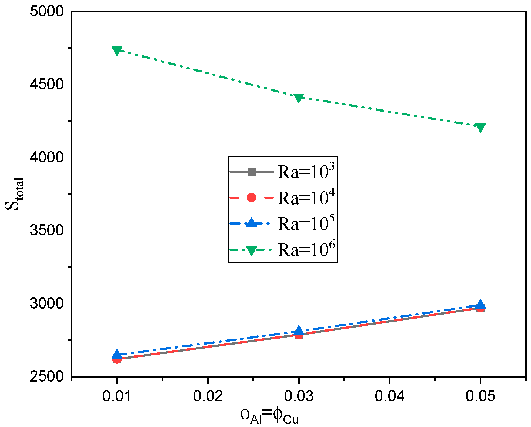
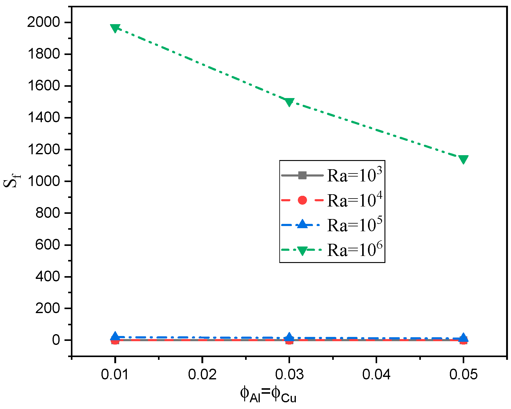
Activity of the hybrid nanofluid as well as the fluid friction entropy are diminished as the H a grows.
3
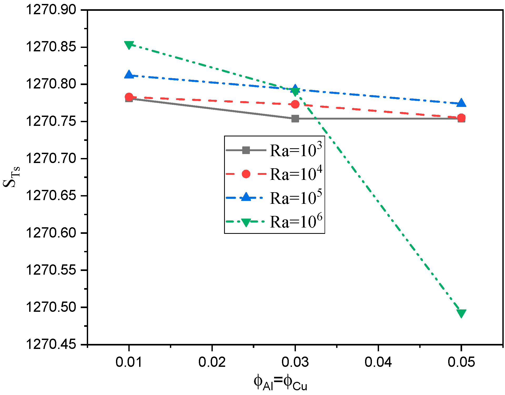
The transfer of heat entropy is augmented as the concentration of the nanoparticles is boosted.
The increase in the γ reduces the Nusselt number while it increases as the Rayleigh number or the volume fraction parameter are growing.
4
From the obtained results, it is recommended to use a non-inclined irregular domain to enhance the heat transfer rate. Additionally, the variable-properties porous medium is more realistic than the porous medium with constant properties.
5
It is recommended to use hybrid nanofluids for enhancement of the heat transfer instead of mono nanofluids.

Author Contributions

Conceptualization: A.A., Z.A.S.R., S.E.A. and W.A.-K.; Investigation, W.A.-K.; Methodology, A.A., Z.A.S.R., S.E.A. and W.A.-K.; Project administration, W.A.-K.; Writing—original draft, A.A., Z.A.S.R., S.E.A. and W.A.-K.; Writing—review & editing, A.A., M.A., S.E.A. and W.A.-K. All authors have read and agreed to the published version of the manuscript.

Funding

This research received no external funding.

Institutional Review Board Statement

Not applicable.

Informed Consent Statement

Not applicable.

Data Availability Statement

Not applicable.

Conflicts of Interest

The authors declare no conflict of interest.

Abbreviation

Nomenclature
A Aspect ratio
B e Bejan number
c p Specific heat capacity ( J   kg 1     K 1 )
C f Inertial coefficient
D a Darcy number
d p Solid particles diameter (m)
g Gravity acceleration ( m   s 2 )
h Heat-transfer coefficient [ W   m 3 K 1 ]
H a Hartmann number
k Thermal conductivity ( W   m 1   K 1 )
K Porous medium permeability ( m 2 )
K r Thermal conductivity ratio
L Bottom wall length ( m )
N u Nusselt number
P Pressure ( N   m 2 )
P r Prandtl number
R a Rayleigh number
S T Entropy generation due to the heat transfer
S f Entropy generation due to the fluid friction
S t o t a l Total entropy
t Time ( s )
T Temperature   ( K )
( u p , v p ) Dimensional velocity component ( ms 1 )
( U p , V p ) Dimensionless velocity component
( x , y ) Cartesian coordinates (m)
( X , Y ) Dimensionless Cartesian coordinates
Greek Symbols
α Thermal diffusivity ( m 2   s 1 )
β Coefficient of thermal expansion ( K 1 )
γ Inclination angle of the cavity vector
τ Dimensionless time
θ Dimensionless temperature
μ Dynamic viscosity ( kg   m 1     s 1 )
ν Kinematic viscosity ( m 2   s 1 )
ρ Density ( kg   m 3     )
ϕ Solid volume fraction
Φ Trapezoidal angle
σ Electrical conductivity
ε Porosity
( ξ , η ) Coordinates of the rectangular domain
Subscripts
effEffective
f Fluid
P Porous medium
h n f Hybrid Nanofluid
h Hot
f p Fluid phase
p Porous phase
C Cold

References

  1. Weber, J.E. The boundary-layer regime for convection in a vertical porous layer. Int. J. Heat Mass Transf. 1975, 18, 569–573. [Google Scholar] [CrossRef]
  2. Burns, P.; Chow, L.; Tien, C. Convection in a vertical slot filled with porous insulation. Int. J. Heat Mass Transf. 1977, 20, 919–926. [Google Scholar] [CrossRef]
  3. Walker, K.L.; Homsy, G.M. Convection in a porous cavity. J. Fluid Mech. 1978, 87, 449–474. [Google Scholar] [CrossRef]
  4. Bejan, A. On the boundary layer regime in a vertical enclosure filled with a porous medium. Lett. Heat Mass Transf. 1979, 6, 93–102. [Google Scholar] [CrossRef]
  5. Prasad, V.; Kulacki, F.A. Natural Convection in a Rectangular Porous Cavity with Constant Heat Flux on One Vertical Wall. J. Heat Transf. 1984, 106, 152–157. [Google Scholar] [CrossRef]
  6. Seki, N.; Fukusako, S.; Inaba, H. Heat transfer in a confined rectangular cavity packed with porous media. Int. J. Heat Mass Transf. 1978, 21, 985–989. [Google Scholar] [CrossRef]
  7. Prasad, V.; Kulacki, F.A.; Keyhani, M. Natural convection in porous media. J. Fluid Mech. 1985, 150, 89–119. [Google Scholar] [CrossRef]
  8. Cheng, P. Heat Transfer in Geothermal Systems. Adv. Heat Transf. 1979, 14, 1–105. [Google Scholar] [CrossRef]
  9. Slattery, J.C. Two-phase flow through porous media. AIChE J. 1970, 16, 345–352. [Google Scholar] [CrossRef]
  10. Poulikakos, D.; Bejan, A. The departure from Darcy flow in natural convection in a vertical porous layer. Phys. Fluids 1985, 28, 3477–3484. [Google Scholar] [CrossRef]
  11. Mohamed, A.B.; Hdidi, W.; Tlili, I. Evaporation of Water/Alumina Nanofluid Film by Mixed Convection Inside Heated Vertical Channel. Appl. Sci. 2020, 10, 2380. [Google Scholar] [CrossRef] [Green Version]
  12. Shah, Z.; OAlzahrani, E.; Dawar, A.; Alghamdi, W.; Zaka Ullah, M. Entropy Generation in MHD Second-Grade Nanofluid Thin Film Flow Containing CNTs with Cattaneo-Christov Heat Flux Model Past an Unsteady Stretching Sheet. Appl. Sci. 2020, 10, 2720. [Google Scholar] [CrossRef] [Green Version]
  13. Shah, Z.; Dawar, A.; Kumam, P.; Khan, W.; Islam, S. Impact of Nonlinear Thermal Radiation on MHD Nanofluid Thin Film Flow over a Horizontally Rotating Disk. Appl. Sci. 2019, 9, 1533. [Google Scholar] [CrossRef] [Green Version]
  14. Ahmed, A.S. FEM-CBS algorithm for convective transport of nanofluids in inclined enclosures filled with anisotropic non-Darcy porous media using LTNEM. Int. J. Numer. Methods Heat Fluid Flow 2020, 31, 570–594. [Google Scholar] [CrossRef]
  15. Rashed, Z.Z.; Ahmed, S.E.; Raizah, Z.A.S. Thermal dispersion and buongiorno’s nanofluid model effects on natural convection in an inclined rectangular enclosure partially filled with heat generating porous medium. J. Porous Media 2020, 23, 341–361. [Google Scholar] [CrossRef]
  16. Ahmed, S.E. Non-Darcian natural convection of a nanofluid due to triangular fins within trapezoidal enclosures partially filled with a thermal non-equilibrium porous layer. J. Therm. Anal. Calorim. 2020, 1–16. [Google Scholar] [CrossRef]
  17. Al-Weheibi, S.M.; Rahman, M.M.; Saghir, M.Z. Impacts of Variable Porosity and Variable Permeability on the Thermal Augmentation of Cu–H2O Nanofluid-Drenched Porous Trapezoidal Enclosure Considering Thermal Nonequilibrium Model. Arab. J. Sci. Eng. 2019, 45, 1237–1251. [Google Scholar] [CrossRef]
  18. Abelman, S.; Parsa, A.B.; Sayehvand, H.-O. Nanofluid flow and heat transfer in a Brinkman porous channel with variable porosity. Quaest. Math. 2018, 41, 449–467. [Google Scholar] [CrossRef]
  19. Saif, R.S.; Muhammad, T.; Sadia, H. Significance of inclined magnetic field in Darcy–Forchheimer flow with variable porosity and thermal conductivity. Phys. A Stat. Mech. Its Appl. 2020, 551, 124067. [Google Scholar] [CrossRef]
  20. Nithiarasu, P.; Seetharamu, K.; Sundararajan, T. Natural convective heat transfer in a fluid saturated variable porosity medium. Int. J. Heat Mass Transf. 1997, 40, 3955–3967. [Google Scholar] [CrossRef]
  21. El-Kabeir, S.M.M.; El-Hakiem, M.A.; Rashad, A.M. Natural Convection from a Permeable Sphere Embedded in a Variable Porosity Porous Medium Due to Thermal Dispersion. Nonlinear Anal. Model. Control 2007, 12, 345–357. [Google Scholar] [CrossRef]
  22. Amiri, A.; Vafai, K. Analysis of dispersion effects and non-thermal equilibrium, non-Darcian, variable porosity incompressible flow through porous media. Int. J. Heat Mass Transf. 1994, 37, 939–954. [Google Scholar] [CrossRef]
  23. Al-Kouz, W.; Kiwan, S.; Alshare, A.; Hammad, A.; Ammar, A. Two-Dimensional Analysis of Low Pressure Flows in the Annulus Region between Two Concentric Cylinders with Solid Fins. Jordan J. Mech. Ind. Eng. 2016, 10, 253–261. [Google Scholar]
  24. Al-Kouz, W.; Alshare, A.; Kiwan, S.; Al-Muhtady, A.; Alkhalidi, A.; Saadeh, H. Two-dimensional analysis of low-pressure flows in an inclined square cavity with two fins attached to the hot wall. Int. J. Therm. Sci. 2018, 126, 181–193. [Google Scholar] [CrossRef]
  25. Al-Kouz, W.; Al-Muhtady, A.; Owhaib, W.; Al-Dahidi, S.; Hader, M.; Abu-Alghanam, R. Entropy Generation Optimization for Rarified Nanofluid Flows in a Square Cavity with Two Fins at the Hot Wall. Entropy 2019, 21, 103. [Google Scholar] [CrossRef] [Green Version]
  26. Mahapatra, T.R.; Saha, B.C.; Pal, D. Magnetohydrodynamic double-diffusive natural convection for nanofluid within a trapezoidal enclosure. Comput. Appl. Math. 2018, 37, 6132–6151. [Google Scholar] [CrossRef]
  27. Li, J.; Yu, B.; Wang, M. Benchmark solutions for two-dimensional fluid flow and heat transfer problems in irregular regions using multigrid method. Adv. Mech. Eng. 2015, 7. [Google Scholar] [CrossRef]
  28. Alsabery, A.; Chamkha, A.; Saleh, H.; Hashim, I.; Chanane, B. Darcian Natural Convection in an Inclined Trapezoidal Cavity Partly Filled with a Porous Layer and Partly with a Nanofluid Layer. Sains Malays. 2017, 46, 803–815. [Google Scholar] [CrossRef]
  29. Alsabery, A.; Chamkha, A.; Hussain, S.; Saleh, H.; Hashim, I. Heatline visualization of natural convection in a trapezoidal cavity partly filled with nanofluid porous layer and partly with non-Newtonian fluid layer. Adv. Powder Technol. 2015, 26, 1230–1244. [Google Scholar] [CrossRef]
  30. Ahmed, S.E.; Mansour, M.A.; Rashad, A.M.; Salah, T. MHD natural convection from two heating modes in fined triangular enclosures filled with porous media using nanofluids. J. Therm. Anal. Calorim. 2019, 139, 3133–3149. [Google Scholar] [CrossRef]
  31. Ahmed, S.E. Natural Convection of Dusty Hybrid Nanofluids in Diverging–Converging Cavities Including Volumetric Heat Sources. J. Therm. Sci. Eng. Appl. 2020, 13. [Google Scholar] [CrossRef]
  32. Mansour, M.A.; El-Aziz, M.M.A.; Mohamed, R.A.; Ahmed, S.E. Thermal nonequilibrium modeling of unsteady natural convection in trapezoidal enclosures in the presence of thermal radiation: Effect of exponential variation of boundary conditions. Spec. Top. Rev. Porous Media Int. J. 2011, 2, 323–333. [Google Scholar] [CrossRef]
  33. Al-Mudhaf, A.F.; Rashad, A.; Ahmed, S.E.; Chamkha, A.J.; El-Kabeir, S. Soret and Dufour effects on unsteady double diffusive natural convection in porous trapezoidal enclosures. Int. J. Mech. Sci. 2018, 140, 172–178. [Google Scholar] [CrossRef]
  34. Ahmed, S.E.; Raizah, Z.A.S. Natural Convection Flow of Nanofluids in a Composite System with Variable-Porosity Media. J. Thermophys. Heat Transf. 2018, 32, 495–502. [Google Scholar] [CrossRef]
  35. Ahmed, S.E.; Hussein, A.K.; Mansour, M.A.; Raizah, Z.A.; Zhang, X. MHD mixed convection in trapezoidal enclosures filled with micropolar nanofluids. Nanosci. Technol. Int. J. 2018, 9, 343–372. [Google Scholar] [CrossRef]
  36. Miroshnichenko, I.V.; Sheremet, M.A.; Oztop, H.F.; Al-Salem, K. MHD natural convection in a partially open trapezoidal cavity filled with a nanofluid. Int. J. Mech. Sci. 2016, 119, 294–302. [Google Scholar] [CrossRef]
  37. Astanina, M.S.; Sheremet, M.A.; Oztop, H.F.; Abu-Hamdeh, N. MHD natural convection and entropy generation of ferrofluid in an open trapezoidal cavity partially filled with a porous medium. Int. J. Mech. Sci. 2018, 136, 493–502. [Google Scholar] [CrossRef]
  38. Al-Kouz, W.; Alshare, A.; Alkhalidi, A.; Kiwan, S. Two dimensional analysis of low pressure flows in the annulus region between two concentric cylinders. SpringerPlus 2016, 5. [Google Scholar] [CrossRef] [PubMed] [Green Version]
  39. Abu-Libdeh, N.; Redouane, F.; Aissa, A.; Mebarek-Oudina, F.; Almuhtady, A.; Jamshed, W.; Al-Kouz, W. Hydrothermal and Entropy Investigation of Ag/MgO/H2O Hybrid Nanofluid Natural Convection in a Novel Shape of Porous Cavity. Appl. Sci. 2021, 11, 1722. [Google Scholar] [CrossRef]
  40. Al-Kouz, W.; Saleem, K.B.; Chamkha, A. Numerical investigation of rarefied gaseous flows in an oblique wavy sided walls square cavity. Int. J. Heat Mass Transf. 2020, 116, 104719. [Google Scholar] [CrossRef]
  41. Al-Kouz, W.G.; Kiwan, S.; Alkhalidi, A.; Sari, M.; Alshare, A. Numerical study of heat transfer enhancement for low-pressure flows in a square cavity with two fins attached to the hot wall using AL2O3-air nanofluid. Strojniški Vestnik-J. Mech. Eng. 2018, 64, 26–36. [Google Scholar]
  42. Zahri, M.; Al-Kouz, W.; Rehman, K.U.; Malik, M. Thermally magnetized rectangular chamber optimization (TMRCO) of partially heated continuous stream: Hybrid meshed case study. Case Stud. Therm. Eng. 2020, 22, 100770. [Google Scholar] [CrossRef]
  43. Ergun, S. Fluid flow through packed columns. Chem. Eng. Prog. 1952, 48, 89–94. [Google Scholar]
  44. Cheng, P.; Hsu, C. Fully-developed, forced convective flow through an annular packed-sphere bed with wall effects. Int. J. Heat Mass Transf. 1986, 29, 1843–1853. [Google Scholar] [CrossRef]
  45. Ahmed, S.E. Caputo fractional convective flow in an inclined wavy vented cavity filled with a porous medium using Al2O3–Cu hybrid nanofluids. Int. Commun. Heat Mass Transf. 2020, 116, 104690. [Google Scholar] [CrossRef]
  46. Buonomo, B.; Manca, O.; Lauriat, G. Forced convection in micro-channels filled with porous media in local thermal non-equilibrium conditions. Int. J. Therm. Sci. 2014, 77, 206–222. [Google Scholar] [CrossRef]
  47. Ilis, G.G.; Mobedi, M.; Sunden, B. Effect of aspect ratio on entropy generation in a rectangular cavity with differentially heated vertical walls. Int. Commun. Heat Mass Transf. 2008, 35, 696–703. [Google Scholar] [CrossRef] [Green Version]
Figure 1. Schematic diagram of the current model.
Applsci 11 01951 g001
Figure 2. Mesh generation of the current geometry.
Applsci 11 01951 g002
Figure 3. Comparisons of the streamlines, isotherms, local Bejan number and local entropy generation due to heat transfer with those of Ilis et al. [47] P r = 0.71 ,   R a = 10 5 ,   φ 1 = 10 4 .
Applsci 11 01951 g003
Figure 4. Features of the streamlines and temperature distributions for the fluid phase and porous phase for the variation of the inclination angle γ ( γ = 0 , π 6 , π 3 , π 2 ) at R a = 10 6 ,   H a = 15 ,   H = 0.1 ,   ϕ A l = ϕ C u = 1 % ,   Φ = π 3 .
Applsci 11 01951 g004
Figure 5. Features of the local entropy generation due to the fluid friction and local Bejan number for the variation of the inclination angle γ ( γ = 0 , π 6 , π 3 , π 2 ) at R a = 10 6 ,   H a = 15 ,   H = 0.1 ,   ϕ A l = ϕ C u = 1 % ,   Φ = π 3 .
Applsci 11 01951 g005
Figure 6. Features of the streamlines and temperature distribution for the fluid phase and porous phase for the variation of the Hartmann number   H a ( H a = 0 , 15 , 25 , 50 , 100 ) at R a = 10 5 ,   H = 0.1 ,   ϕ A l = ϕ C u = 1 % ,   Φ = π 3 , γ = 0 .
Applsci 11 01951 g006
Figure 7. Features of the local entropy generation due to the fluid friction and local Bejan number for the variation of the Hartmann number   H a ( H a = 0 , 15 , 25 , 50 , 100 ) at R a = 10 5 ,   H = 0.1 ,   ϕ A l = ϕ C u = 1 % ,   Φ = π 3 , γ = 0 .
Applsci 11 01951 g007
Figure 8. Profiles of the Nuf for the variation of the inclination angle γ ( γ = 0 , π 6 , π 3 , π 2 ) at R a = 10 6 ,   H a = 15 ,   H = 0.1 ,   ϕ A l = ϕ C u = 1 % ,   Φ = π 3 .
Applsci 11 01951 g008
Figure 9. Profiles of the Nuf for the variation of the Rayleigh number and nanoparticle volume fraction ϕ A l = ϕ C u at   H a = 15 ,   H = 0.1 ,   γ = π / 6 ,   Φ = π 3 .
Applsci 11 01951 g009
Figure 10. Profiles of the ST of the nanofluid phase in the entire domain for the variation of the Rayleigh number and nanoparticle volume fraction ϕ A l = ϕ C u at   H a = 15 ,   H = 0.1 ,   γ = π / 6 ,   Φ = π 3 .
Applsci 11 01951 g010
Figure 11. Profiles of the Stotal in the entire domain for the variation of the Rayleigh number and nanoparticle volume fraction ϕ A l = ϕ C u at   H a = 15 ,   H = 0.1 ,   γ = π / 6 ,   Φ = π 3 .
Applsci 11 01951 g011
Figure 12. Profiles of the STS of the solid phase in the entire domain for the variation of the Rayleigh number and nanoparticle volume fraction ϕ A l = ϕ C u at   H a = 15 ,   H = 0.1 ,   γ = π / 6 ,   Φ = π 3 .
Applsci 11 01951 g012
Figure 13. Profiles of the Sf in the entire domain for the variation of the Rayleigh number and nanoparticle volume fraction ϕ A l = ϕ C u at   H a = 15 ,   H = 0.1 ,   γ = π / 6 ,   Φ = π 3 .
Applsci 11 01951 g013
Table 1. Properties of the components of the hybrid nanofluid.
PropertyH2OCuAl2O3
ρ997.189333970
Cp4179385765
k0.61340140
β21 × 10-51.67 × 10-50.85 × 10⁻⁵
σ0.055.96 × 1071 × 10-10
Table 2. Grid independency test at R a = 10 5 ,   H = 0.1 ,   H a = 10 ,   ϕ A l = ϕ C u = 1 % ,   Φ = π 3 , γ = 0 .
Grid Size ( N u f ) a v ( N u s ) a v
31 × 31 1.3964002.751032
41 × 41 1.2978732.877911
61 × 61 1.9356343.034790
81 × 81 1.9645313.125698
101 × 101 1.9934293.196916
121 × 121 2.0219423.259058
Publisher’s Note: MDPI stays neutral with regard to jurisdictional claims in published maps and institutional affiliations.

