
Seismic Performance of LRS-FRP–Concrete–Steel Tubular Double Coupling Beam

Guangdong Provincial Key Laboratory of Durability for Marine Civil Engineering, Shenzhen University, Shenzhen 518000, China
*
Author to whom correspondence should be addressed.
Appl. Sci. 2021, 11(5), 2024; https://0-doi-org.brum.beds.ac.uk/10.3390/app11052024
Submission received: 3 February 2021
/
Revised: 20 February 2021
/
Accepted: 21 February 2021
/
Published: 25 February 2021
(This article belongs to the Special Issue Structural Performances of Concrete Composite Members: Experimental, Theoretical, Numerical Approaches II)
Abstract
:To improve the ductility and seismic performance of a double coupling beam, the authors applied a polyethylene terephthalate (PET) sheet and steel tube to form fiber-reinforced polymer (FRP)–concrete–steel double-skin tubular (DST) composite coupling beams. A low-cyclic reversed experimental program was carried out which factored in the member form, steel tube diameter, and construction methods. The results indicate that the ductility and energy dissipation performance of double coupling beams—whether wrapped with a PET-FRP sheet or surrounded by an FRP–concrete–steel DST composite system—is a substantial improvement over the traditional reinforced-concrete double coupling beam (RC-DCB). The ductility coefficient and accumulated energy dissipation of the DST-DCB members improved above 170% and 2300%, respectively. These percentages compare to the RC-DCB and are based on the rupture of a PET-FRP sheet. The results are similar to those of the large rupture strain double coupling beam (LRS-DCB). Meanwhile, the external wrapped PET-FRP sheet does not affect the initial stiffness and peak strength of the RC-DCB. Relatively, the inner steel tube will improve the initial stiffness, yielding strength, and peak strength. DST-DCB members still have considerable deformability after 85% of peak strength since the external PET-FRP sheet provided an effective constraint effect on the core concrete and the inner steel tube could bear excellent shear deformation.
1. Introduction
Shear wall structures and frame-shear wall structures are widely used in high-rise buildings. As an important structural member of these structures, the coupling beam is usually designed as the energy-dissipating member that produces a plastic hinge after yielding, making it the first line of defense for anti-seismic energy dissipation. Under the action of seismic load, the coupling beam will yield and fail, and act as energy dissipation, to avoid the premature failure of the wall limb. Due to the characteristics of the small span-height ratio and large stiffness of the connected shear wall, the coupling beam is prone to brittle shear failure. To improve the mechanical behavior of the coupling beam, scholars have developed many strategies since the 1970s. The research plans generally focus on improving the following three aspects: new reinforcement forms [1,2], steel–concrete composite members [3], and using high-performance concrete [4]. However, these strategies are not ideal for improving the ductility or energy consumption of the coupling beam [4], and some of them even limit the thickness of the beam.
With the development and application of fiber-reinforced polymer (FRP) in civil engineering, Teng et al. developed a new type of hybrid FRP-concrete-steel double-skin tubular (DST) composite member in 2004 [5,6], which consists of an external FRP tube, internal steel tube, and reinforced concrete (RC) in the sandwich. Different components in the system work well together. The outer FRP tube has a good restraint effect on the sandwich concrete, which improves the strength, plasticity, and toughness of concrete. At the same time, the confined concrete can also prevent the buckling of the internal steel tube. This type of composite member presents excellent anti-seismic performance, ductility, and corrosion resistance. In 2006, Yu et al. [7] researched the flexural mechanical behavior of hybrid glass FRP (GFRP)–concrete–steel beams. They found this DST-GFRP composite beam to have excellent flexural capability and ductility, especially when the inner steel tube is reasonably offset toward the tensile zone. However, the bonding behavior between concrete and its steel tube interface needs to be improved. The test results indicate that interface slippage would result in obvious load fluctuations—even sudden drops, which is a threat to structural safety. The research carried out by Idris and Ozbakaloglu [8,9] shows that the bond behavior could be improved significantly by using mechanical connectors. Meanwhile, the novel composite system presented in this article also presents good ductility under cyclic loading, and the ductility performance of the composite beam would not be significantly weakened by the inner steel tube filled with concrete.
Moreover, the compressive behaviors of FRP-concrete steel double-skin tubular columns under both monotonic and cyclic loads have also been investigated by some scholars [10,11,12,13,14,15,16,17,18]. Except for the good ductility and anti-seismic performance, [13,14] also indicated that the ductility could be improved by filling concrete at both ends of the inner steel tube, while [19,20] recommended using a stiffener-reinforced steel tube. For the compressive behavior of large rupture strain FRP (LRS-FRP), the rupture strain was usually larger than 5% (as in the case of a polyethylene terephthalate, PET) wrapped concrete-steel column, some researchers [21,22,23] have also reported that the corresponding composite system has a good bearing capacity and ductility, with an ultimate compressive strain in some cases reaching up to 15%. Notably, Wang et al.’s [24] test results show that the failure mode of the composite column tends to be a brittle failure when using ultra-high-performance fiber-reinforced concrete instead of traditional concrete.
As just mentioned, the application of an FRP-concrete-steel DST composite member is mainly concentrated in the RC column and beam. For this type of coupling beam with a small span-height RC member, the corresponding research is rarely reported. Based on the excellent performance of the DST system on the flexural behavior of composite beams and the great ductility performance of DST composite columns, the authors applied LRS-FRP to the DST double coupling beam to form an LRS-FRP-concrete-steel DST composite coupling beam. In which, the double coupling beam not only facilitates the arrangement of pipeline lines but also significantly reduces the internal force of the coupling beam and improves the seismic performance of the coupling beam. However, it has an unavoidable disadvantage of rapid degradation of stiffness and bearing capacity at a later stage [25]. This paper features the authors’ quasi-static low-cycle reversed loading experimental program carried out to research the bearing capacity, ductility, and energy dissipation of LRS-FRP-concrete-steel DST double coupling beams.
2. Materials and Methods
2.1. Specimen Design
A total of five coupling beams were manufactured and tested by considering the cross-section form, diameter of the inner steel tube, and construction technology. As shown in Figure 1, the geometry of the coupling beam is 200 mm in width, 900 mm in length, and 600 mm in height. Figure 2 illustrates the brief manufacturing processes of specimens. The control specimen is one double RC double coupling beam (RC-DCB). The specimen, LRS-DCB, is one double RC coupling beam wrapped with one PET sheet. The difference between RC-DCB and LRS-DCB is the extra wrapped PET sheet. The details of these two specimens are illustrated in Figure 1a. The other three coupling beams are LRS-FRP-concrete-steel DST double coupling beams, as shown in Figure 1b, the differences between them are the diameter of the inner steel tube and the manufacturing method. Thus, DST-DCB-89 is one double coupling beam with an inner steel tube of 89 mm diameter and wrapped with one PET-FRP sheet; DST-DCB-76 is one double coupling beam with an inner steel tube of 76 mm diameter and wrapped with one PET-FRP sheet; DST-DCB-89P is one precast double coupling beam, as shown in Figure 2, with an inner steel tube of 89 mm diameter and wrapped with one PET-FRP sheet. The details of all specimens are listed in Table 1.
2.2. Material Property
The materials used in this test program include concrete, polyethylene terephthalate (PET) FRP sheets, steel bars, and steel tubes. The average compressive strength of concrete was 20.2 MPa, determined by testing three cylinders with a diameter of 150 mm and a height of 300 mm based on the test code of China GB50152-2012T [26]. According to the Chinese code GB50010-2016 [27], the modulus of elasticity of concrete is taken as 30GPa. The material properties of PET-FRP are listed in Table 2 and Figure 3, in which the coupon tested data were obtained by the axial tensile test of five specimens with a width of 25 mm based on the test code of American society for testing and materials (ASTM) D3039-2015 [28]. The material properties of reinforcement and steel tube are tested based on China’s code GB/T 228-2010 [29] and illustrated in Table 3 and Figure 3.
2.3. Test Setup
2.3.1. Loading Equipment and Scheme
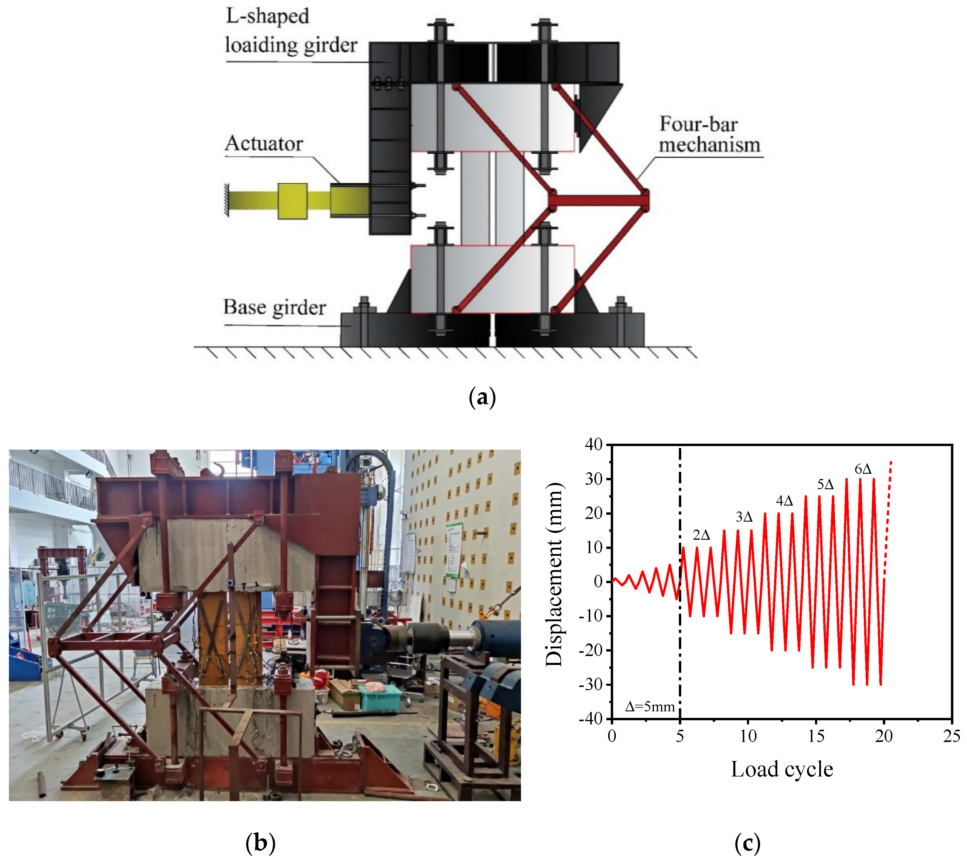
Figure 4 illustrates the test setup for the quasi-static low-cycle reversed loading experiment. To make sure the loading scheme replicates the real situation of the coupling beam, as shown in Figure 4a,b, the equipment consists of four parts that were designed, fabricated, and applied in the test. Notably, the coupling beam was rotated 90° and erected along the longitudinal axis of the specimen. From this point, the coupling beam was connected with the bottom foundation and top L-shaped loading girder through a four-bar mechanism. The top L-shaped girder transmitted the load from the 500 kN hydraulic servo-system to the coupling beam. In addition, the four-bar mechanism can ensure that the horizontal force applied in the loading process is always in the loading plane and remains horizontal. Meanwhile, the four-bar mechanism can prevent torsion from occurring in the top steel beam due to the failure of the ends of the coupling beam under large deformation.
The displacement control was adopted during the whole testing process illustrated in Figure 4c according to the following actions:
- One relatively small cyclic horizontal force was applied to the coupling beam to check whether the loading equipment, instrumentation, and acquisition equipment were working properly.
- The horizontal displacement of each cycle was set to increase by 1 mm in each turn until loading to 5 mm.
- The amplitude was then set to 5 mm and cycled three times under each displacement level.
- The specimen was examined and considered to be invalid until its ultimate bearing capacity dropped below 85% of the maximum bearing capacity or the wrapped PET-FRP sheet ruptured.
2.3.2. Data Measurement
The recorded data are mainly used for analysis of the hysteretic curve, shear and longitudinal deformation of the double coupling beam, and the anti-seismic performance of the DST coupling beam. The horizontal force V and displacement Δ were recorded by the dynamic acquisition box produced by DEWEsoft DAQ software ver. X2 SP. This system can present the real-time force-displacement curve, which helps to accurately determine changes in force and displacement.
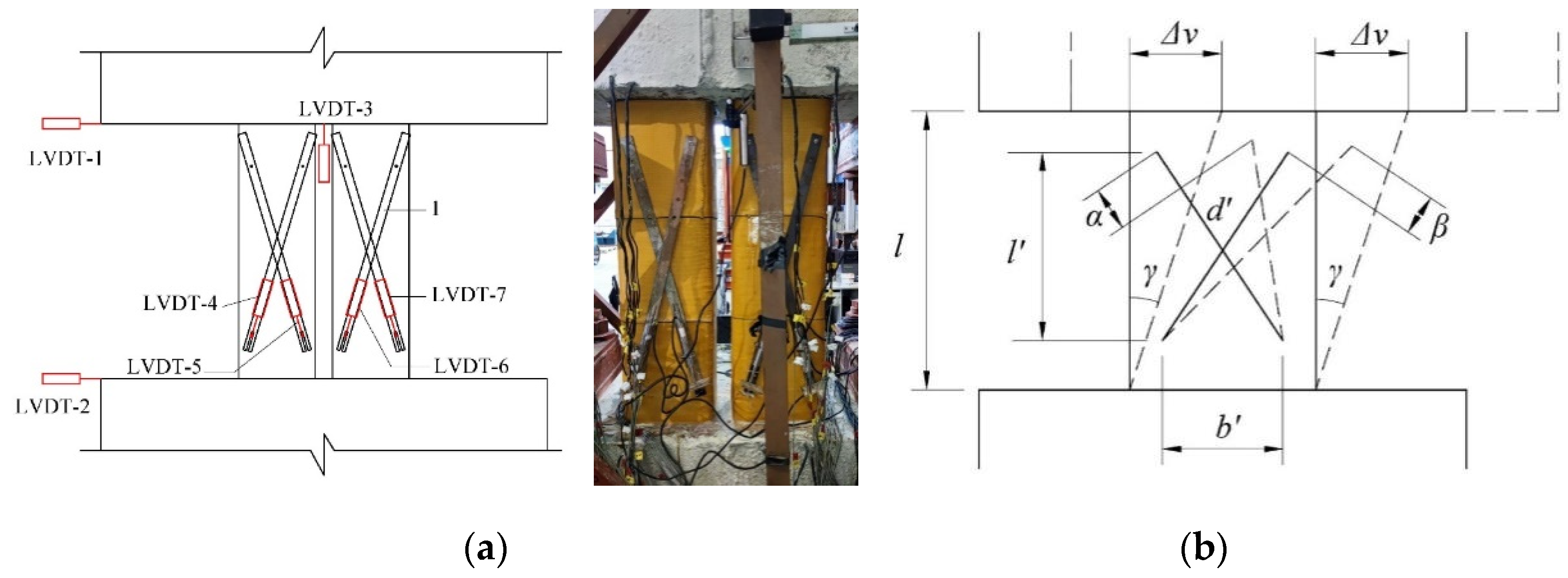
Strain gauges 5 mm in length were used to measure the strains of steel bars and PET sheet. Figure 5 illustrates the strain gauge locations. Figure 6 shows the horizontal deformation of the composite system, which was recorded by two linear variable differential transformer displacement sensors (LVDT, LVDT-1, and LVDT-2 in Figure 6a). The longitudinal deformation was recorded by LVDT-3. The shear deformation of the coupling beam, as illustrated in Figure 6b, was obtained by transforming the test data from LVDT4–7 (as illustrated in Figure 6a) by calculating Equation. (1).
where Δv and l are the shear deformation and initial length of the coupling beam, respectively; γ is the deflection angle between the initial and real-time state of the coupling beam, which can be calculated as γ = d′(α + β)/(2l′b′). As illustrated in Figure 6, d′ is the initial length of LVDT, while l′ and b′ are the initial projection lengths of the LVDTs in the corresponding direction. Finally, α and β are the length change of two LVDTs.
Δv = γl
3. Results and Discussion
3.1. Failure Modes
The failure modes of the specimens are shown in Figure 7. Notably, only the failure behavior of specimen DST-DCB-89 appears in Figure 7 due to the similarity of the failure modes in each of the three coupled beams with inner steel tubes. Three different kinds of failure modes are illustrated in Figure 7. Compared to cross diagonal cracks observed in specimen RC-DCB (Figure 7a), specimen LRS-DCB was noticeably strengthened with the PET-FRP wrap as evidenced by the appearance of more flexural cracks and fewer shear cracks at both ends. Relatively speaking, specimen DST-DCB-89 presented one main bending crack in the plane perpendicular to the force direction and yet the concrete was crushed.
As for the control specimen RC-DCB, some shear cracks were generated one by one before the longitudinal reinforcements yielded. Then, one small bending crack was generated after longitudinal bar yield. Finally, with the deformation increase, the spalling of concrete resulted in a sudden drop in bearing capacity.
The damage processes of the other specimens during testing were similar to each other. With the extra wrapped PET-FRP material, no obvious shear crack appeared during the testing process. As shown in Figure 7b,c, the location of the observed first crack was at the junction of the coupling beam and end block. Then all these specimens reached the peak strength. With the deformation increase, the horizontal cracks were generated near the end of the coupling beam.
After artificially removing the PET-FRP jacket and concrete, the specimens LRS-DCB and DST-CB-89 presented two different failure modes in Figure 7. In Figure 7b, many cracks are shown as generated at the plastic hinge areas at both ends of the specimen LRS-DCB. Furthermore, one main crack appeared at the junction of the beam and on the end block. Figure 7c shows serious concrete crushing and local buckling of the steel tube occurring in those specimens with inner steel tubes. The primary analysis concluded that the local buckling of the inner tube invalidated any blame on the constraining effect to concrete provided by the PET-FRP material; then, concrete started crushing as the deformation increased. When the crushed concrete filled the gap and the deformation increased, the constraining effect of the PET-FRP sheet controlled the attenuation of the bearing capacity.
3.2. Hysteretic Curve
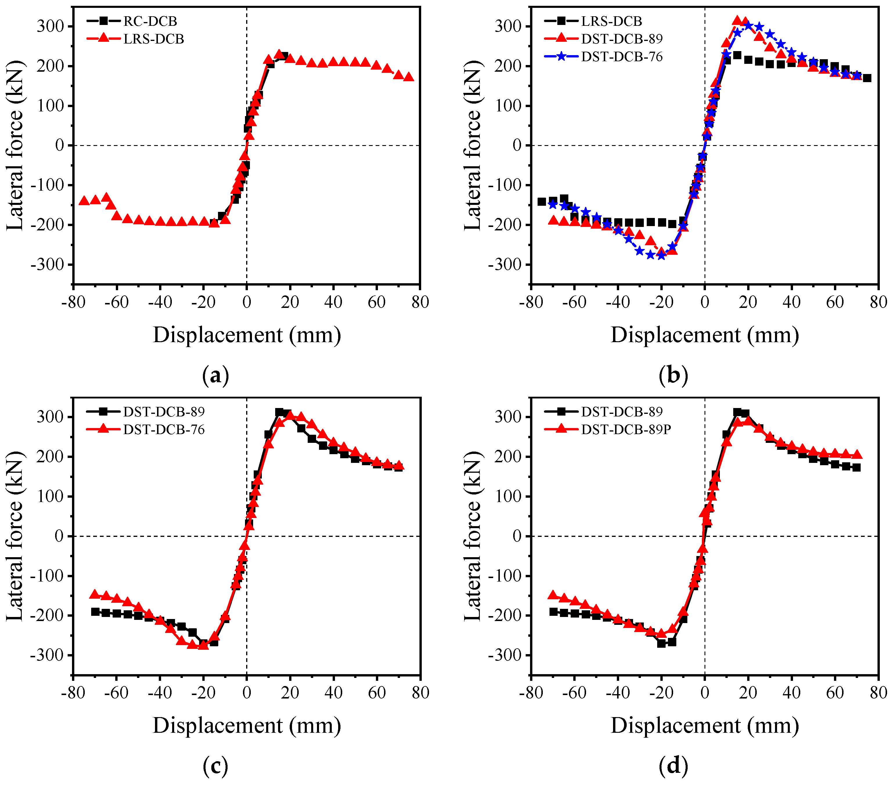
The load-displacement curves of all coupling beams under low-cyclic reversed loading, namely hysteretic curves, which could reflect the seismic performance of members, such as the ductility, energy dissipation, and stiffness degeneration. Usually, the plumper the hysteretic curve is, the better the energy dissipation and the better the seismic performance. As illustrated in Figure 8, those curves of specimens with a double coupling beam (DCB) wrapped with LRS-FRP or consisting of double skin tubular (DST) beams, which are wider and have better ductility than the control DCB specimen.
Since there is no obvious yielding point in the envelope curves of all specimens, the yielding point of these members is determined by the method reported by Park [30]. As illustrated in Figure 9, which shows the point set corresponding to the 75% peak strength at point B. Then, point A is the intersection of the OB extension line and the horizontal line corresponding to the peak strength. Finally, we can define the interaction of the load-displacement curve and the perpendicular line passing through point A near the displacement axial as the yielding point (point Y in Figure 9). The calculated yield strength and corresponding deformation of the specimens are listed in Table 4.
For the control specimen RC-DCB, as shown in Figure 8a, the force increases elastically before a crack generates. With the deformation increase, the cumulative damage expands and the stiffness degrades gradually. The specimen reaches the yielding stage when the longitudinal reinforcement yields. Then the load bearing capacity of the specimen can hardly be further improved. With the shear cracks generating and developing, the stiffness of the specimen is further reduced. Before the occurrence of shear failure, the load dropped suddenly, which also resulted in the ultimate lateral deformation being very small relative to the other strengthened specimens.
Compared to the control RC-DCB, as illustrated in Figure 8, Figure 9 and Figure 10, and Table 4, the ductility of the specimen LRS-DCB improved significantly. The ultimate lateral deformation increased 284% although its peak bearing capacity was similar to that of the RC-DCB specimen. Figure 10 shows that the pre-peak stage of LRS-DCB is almost the same as that of RC-DCB. This means that according to a lower Young’s modulus of the PET-FRP material, a constraining stiffness develops but is not able to further improve the core RC beam’s bearing capability in the initial stage. However, the bearing capacity presents a relatively stable state after a slight reduction. This indicates that with the deformation increase the constraint effect provided by the LRS-FRP composite jacket makes a great contribution toward maintaining the bearing capacity and improving the ductility of the coupling beam. For the cycling behavior of LRS-DCB, it presents an obvious pinching phenomenon, i.e., the LRS-DCB specimen needs only a small lateral force to restore its original position after the force unloads to zero. Notably, the well-known ultra-high rupture strain of the PET-FRP material could provide relatively high constraint stress to the core concrete in the stage of large deformation. In this case, even its Young’s modulus is relatively much lower than that of traditional CFRP. Meanwhile, the existing experiments and theories [31] indicate that the compressive and shear strength of concrete could be improved due to its effective multi-axial constraining stress. This makes it possible to maintain its bearing capacity even under large deformation. However, the large lateral deformation is also accompanied by concrete damage. This damage also results in the reduction of tension and shear strength. After measuring the lateral deformation, go back to zero. The bearing capacity contributed by concrete changes from compression to shear. The concrete damage and the slippage between steel bar and concrete resulted in the pinching phenomenon.
Relatively, the hysteretic curves of the specimens DST-DCB-89, DST-DCB-76, and DST-DCB-89P illustrated in Figure 8 are similar to each other except for some details. Compared to the specimen, LRS-DCB, as shown in Figure 8, Figure 10, and Table 4, the yield stress, peak stress, ultimate stress, and corresponding deformation of DST-DCB-89, DST-DCB-76, and DST-DCB-89P improved significantly: (1) the yielding stress of these three specimens improved by 41%, 37%, and 27%, respectively. Meanwhile, the corresponding lateral deformation improved by 20%, 31%, and 20%, respectively; (2) the peak stress of these three specimens improved by 39%, 38%, and 27%, respectively. The corresponding lateral deformation improved by 8%, 23%, and 23%, respectively; (3) the ultimate stress was based on 85% of the peak strength of these three specimens improved by 18%, 17%, and 8%, respectively. The corresponding lateral deformation decreased by 71%, 115%, and 121%, respectively. Moreover, the ductility coefficient of specimens LRS-DCB, DST-DCB-89, DST-DCB-76, and DST-DCB-89P improved by 292%, 42%, 65%, and 82%, respectively, based on the 85% peak strength compared to the control specimen.
Compared to the peak stress and ultimate stress of those DST-DCB specimens, we determined that the the bearing capacity enhancement was mainly caused by the embedded steel tube. As the lateral deformation and cycle times increase, the bearing capacity also increases until the inner steel tube buckling due to insufficient support inside. Compared to the LRS-DCB specimen, the force of those three specimens with DST dropped rapidly at first and then stabilized. However, as shown in Figure 10 and Table 4, the strengths of the four specimens are similar to each other when the wrapped PET-FRP sheet ruptures, indicating that the wrapped PET-FRP jacket’s constraint effect could effectively prevent further reduction of the bearing capacity. Hence, the enhanced strength of those DST-DCB specimens could act as energy storage for the specimen design. As shown in Table 4, the deformation of DST-DCB-89, DST-DCB-76, and DST-DCB-89P corresponding to the PET-FRP rupture improved by 300%, 253%, and 300%, respectively, compared to the control specimen. These results are similar to those recorded for the LRS-DCB specimen. Meanwhile, compared to the control specimen the ductility coefficient of the LRS-DCB, DST-DCB-89, DST-DCB-76, and DST-DCB-89P specimens improved by 292%, 232%, 171%, and 233%, respectively, based on the rupture of the PET-FRP sheet. This indicates that the ductility of DCBs can be improved greatly by the external PET-FRP wrapping or in the form of a DST composite member.
Moreover, the hysteretic part of these curves is relatively wider than those of specimens DCB and LRS-DCB. The reason is that the steel tube could contribute to both shear and compression except for the concrete and reinforcement, which allows the component to absorb more energy under repeated loading. Compared to those curves in Figure 8c–e, the pinching phenomenon of specimen DST-DCB-79 is more prominent than specimens DST-DCB-89 and DST-DCB-89P. Notably, the prefabricated component has similar properties to the cast-in-place component.
3.3. Shear Deformation
The shear deformations of all specimens are illustrated in Figure 11. Compared to the control double coupling beam, the shear deformations corresponding to the ultimate strength of the specimens LRS-DCB and DST coupling beams are improved significantly. This means the wrapping PET-FRP sheet and inner steel tube make a great contribution to the shear ductility of the coupling beam.
The results shown in Figure 11 indicate that the corresponding shear deformations of those DST beam specimens are slightly larger than that of the LRS-DCB specimen. Meanwhile, as the diameter of the inner steel tube decreases, the corresponding shear deformation increases. However, compared to the results in Figure 8 and Figure 11, it is evident that the ratio between the shear deformation and total deformation of the specimens LRS-DCB, DST-DCB-89, DST-DCB-76, and DST-DCB-89P is 21%, 58%, 61%, and 49%, respectively. The flexural deformation of LRS-DCB is better than that of the DST coupling beams. Notably, the reason the shear deformation of the LRS-DCB specimen decreased before reaching the ultimate state, as shown in Figure 11b, is that the bending cracks at both ends of the LRS-DCB specimen (Figure 7b) resulted in a decrease in the recorded data by the linear variable differential transformers (LVDTs).
4. Seismic Performance
The mechanical behavior of the concrete members under low cyclic reversed loading is one of the important methods used to evaluate their seismic performance. The following four parameters, namely strength degradation, stiffness degradation, ductility performance, and energy dissipation, were analyzed to investigate the seismic performance of the composite coupling beams.
4.1. Strength Degradation
Three reverse cycles were carried out under each displacement level. With the cycle increase, the corresponding bear capacity of the specimen decreases. Usually, the coefficient of strength degradation λi is used to reflect the degree of strength reduction, which can be calculated as follows [32]:
where j is the number of main cycles starting from the skeleton curve; i is the number of sub-cycle at each main cycle j; corresponds to the strength on the skeleton curve, and is the strength at sub-cycle i.
Figure 12 represents all specimens by showing the coefficient of strength degradation decreasing when the cycles increased under constant deformation. Relatively speaking, the phenomenon between these coefficients presents an obvious difference based on the deformation increase.
For the RC-DCB, specimen only two displacement levels were carried out due to the ductility shortcoming. Meanwhile, the coefficient only exhibited a monotone decreasing phenomenon with the displacement increase due to the damage accumulation.
For the other four specimens, as shown in Figure 12b–e, the coefficient tends to decrease first and then increase. Compared to the specimens embedded with a steel tube, the coefficient of the LRS-DCB specimen even shows two troughs, which also reflect the difference between the two systems: (1) the first trough indirectly reflects the peak strength of the LRS-DCB specimen. Before this trough, the damage accumulation of the LRS-DCB specimen was mainly caused by concrete, the concrete–steel interface, and yielding of reinforcement, which is similar to that of the RC-DCB specimen because the PET-FRP constraint had not been activated. After that, the further damage of concrete was limited by the increasing constraint stress provided by the PET-FRP material, which resulted in the value of the coefficient recovered. However, the constraint stiffness decreased when the strain of PET-FRP material reached the second stage in Figure 3a, then the damage accumulation during the subsequent cycles increased again. (2) Relatively speaking, there is only one trough in those specimens embedded with steel tubes. Notice that the values of λi corresponding to the trough of LRS-DCB are similar to each other, which means that the relatively larger coefficients corresponding to the trough of the DST-DCB specimens were caused by the slippage of the concrete-tube interface and the buckling of the steel tube. After that, the constraint effect provided by the steel tube and PET-FRP sheet limited the further damage of concrete, which resulted in the decrease of the coefficient. Unlike the performance of LRS-DCB, the coefficient tends to show a monotone increase after the trough. This indicates that the state of the specimens tends to be stable.
4.2. Stiffness Degradation
The stiffness reflects the ability of the member to resist deformation under loading. The stiffness of specimens reduces with the fracture of concrete, the cracking of LRS-FRP, the buckling of steel tubes, and slippages between steel and concrete. The secant stiffness was used to analyze the stiffness degradation of specimens, which can be calculated with Equation (3).
where, +Fj and −Fj are the positive and negative strength corresponding to the current maximum positive deformation +Xj and the maximum negative deformation +Xj, respectively.
The normalized stiffness is the stiffness ratio between each main cycle Kj and the first cycle K1. The normalized stiffness of all specimens is illustrated in Figure 13. Compared to the control specimen RC-DCB, the stiffness of the other strengthened specimens dropped slightly slower in the initial stage due to the effect of the external wrapped PET-FRP sheet or the inner steel tube. Since the limited constraint effect is provided by the PET-FRP material, the normalized stiffness of the LRS-DCB specimen dropped faster than those with embedded steel tubes in the initial stage. With the deformation increase, the increasing confined stress limited the stiffness degradation, which caused the slope of the curves to flatten out. The initial stiffness of the DST-CB specimens was mainly controlled by the inner steel tube, which dropped at a slower rate than that of the LRS-DCB specimen. With the increase of deformation, the inner steel tube yielded, and the PET-FRP material constraint effect controlled the stiffness degradation of the specimens.
4.3. Energy Dissipation
Energy dissipation performance reflects the energy consumption capacity of components under earthquake action. Usually, the fuller the hysteretic curve is, the stronger the energy dissipation performance, and the better the seismic performance. Under repeated loading, the member absorbs external energy during loading and releases energy during unloading. The subtraction of the energy during the cycle is defined as energy dissipation, as shown in Figure 14, which is equal to the area surrounded by the hysteresis loop. The equivalent viscous damping coefficient, ξeq calculate with Equation (4), and the cumulative energy dissipation, ΣS, can be used to evaluate the energy dissipation capacity of members in an earthquake.
As shown in Figure 15a, the cumulative energy dissipation has shared similarities before yielding. The DCB specimen yields first resulting in cumulative energy dissipation, which increased faster than the others. The total cumulative energy dissipation of the LRS-DCB specimen and the DST-DCB coupling beams were improved significantly relative to the DCB control specimen. Compared to the control specimen, the cumulative energy dissipation of the LRS-DCB, DST-DCB-89, DST-DCB-76, and DST-DCB-89P specimens corresponding to Δu improved by 2019%, 376%, 496%, and 500%, respectively. Moreover, the cumulative energy dissipation of the LRS-DCB, DST-CB-89, DST-CB-76, and DST-CB-89P specimens corresponding to Δu,frp improved by 2352%, 2877%, 2345%, and 2660%, respectively, compared to the control specimen. This indicates that the energy dissipation performance of the coupling beam could be greatly improved by wrapping one PET-FRP sheet. The DST composite system also presents excellent energy dissipation. In addition, the results indicate that the tube’s diameter has a slight positive effect on the energy dissipation behavior of the coupling beam.
On the other hand, compared to the control specimen, the equivalent viscous damping coefficients of the other four specimens are similar to each other when the displacement is less than 10 mm. The strengthened PET-FRP sheet delays concrete damage and steel bar yielding, which results in the coefficient of the control specimen being larger than that of the other four specimens. Then, the concrete damage results in the coefficients of the DCB and LRS-DCB specimens increasing faster than the coefficient of the DST coupling beams. With the deformation increase, the constraint effect provided by the PET-FRP sheet controlled any further concrete damage, and the coefficient of the LRS-DCB specimen became stable. Relatively speaking, the coefficients of those DST coupling beams tend to attain a linear increase with the deformation increase. The main reason for this is that the constraint effect provided by the PET-FRP sheet and inner steel tube decreased the early damage of concrete.
5. Conclusions
In this paper, a PET-FRP sheet and steel tube were applied to form FRP-concrete-steel double-skin tubular (DST) composite coupling beams. The seismic performance was tested on three types of double coupling beams (DCBs) (namely RC-DCB, LRS-DCB, and DST-DCB), through an experimental program. The following conclusions were drawn:
- The ductility and energy dissipation performance of the double coupling beams either wrapped with a PET-FRP sheet or consisting of an FRP-concrete-steel DST composite system is improved significantly compared to the traditional RC-DCB. The ductility coefficient and accumulate energy dissipation of the DST-DCB members based on the rupture of the PET-FRP sheet are similar to that of the LRS-DCB, which improved above 170% and 2300%, respectively, compared to the RC-DCB.
- The external wrapped PET-FRP sheet does not affect the initial stiffness and peak strength of the RC-DCB. However, under the same conditions, the inner steel tube will improve the initial stiffness, yielding strength, and peak strength.
- The DST double coupling beams still have considerable deformability after 85% of peak strength has been distributed since the external PET-FRP sheet was able to provide an effective constraint effect on the core concrete and the inner steel tube allowing it to bear excellent shear deformation. The improved strength of the DST-CB can now serve as energy storage for the double coupling beam.
What should be mentioned here is that, due to the limited number of test specimens, some parameters were not considered. For example, the influence of steel pipe diameter-thickness ratio on the seismic performance of the composite structure, which could be analyzed by using the finite element method. However, the numerical method in reference [33] indicated that the finite element model should use a reliable three-dimensional constitutive model for the concrete, which needs to fully consider the unique characteristics of PET-FRP confined concrete. Furthermore, based on the test and finite element analysis, the equations for predicting the bearing capacity of the LRS-FRP-concrete-steel DST double coupling beams could also be further researched.
Author Contributions
Conceptualization, Y.Z.; methodology, L.S.; validation, B.H. and C.C.; formal analysis, Z.Z., B.H. and C.C.; investigation, Z.Z., Y.L. and Y.Z.; resources, Y.Z.; writing—original draft preparation, Z.Z. and Y.L.; writing—review and editing, Y.Z. and L.S.; visualization, Z.Z. and Y.L.; funding acquisition, L.S. and Y.Z.; project administration, Y.Z. and L.S. All authors have read and agreed to the published version of the manuscript.
Funding
This research was funded by the National Natural Science Foundation of China (Grants No. 51778371, 51878414 and 51978412), the National Key Research and Development Project of China (2018YFE0125000), the Shenzhen City’s basic research project (JCYJ20190808154805456), and the Guangdong Provincial Key Laboratory of Durability for Marine Civil Engineering (SZU, 2020B1212060074).
Institutional Review Board Statement
Not applicable.
Informed Consent Statement
Not applicable.
Data Availability Statement
The data presented in this study are available on request from the first author and corresponding authors.
Conflicts of Interest
The authors declare no conflict of interest.
References
- Park, R.; Paulay, T. Reinforced Concrete Structures; John Wiley and Sons: New York, NY, USA, 1975. [Google Scholar]
- Tegos, I.; Penelis, G. Seismic Resistance of Short Columns and Coupling Beams Reinforced with Inclined Bars. ACI Struct. J. 1988, 85, 82–88. [Google Scholar]
- Subedi, N.K.; Baglin, P.S. Plate reinforced concrete beams: Experimental work. Eng. Struct. 1999, 21, 232–254. [Google Scholar] [CrossRef]
- Zhang, H.Z.; Zhang, R.J.; Huang, C.K. Experimental study of shear resistance of steel fiber reinforced high-strength concrete coupling beams. China Civil. Eng. J. 2007, 40, 15–22. (In Chinese) [Google Scholar]
- Teng, J.G.; Yu, T.; Wong, Y.L. Hybrid FRP-concrete-steel double-skin tubular columns: Stub column tests, International Conference on Steel and Composite Structures [ICSCS]. In Proceedings of the Second International Conference on Steel & Composite Structures, Seoul, Korea, 2–4 September 2004. [Google Scholar]
- Teng, J.G.; Yu, T.; Wong, Y.L.; Dong, S.L. Hybrid FRP–concrete–steel tubular columns: Concept and behavior. Constr. Build. Mater. 2007, 21, 846–854. [Google Scholar] [CrossRef]
- Yu, T.; Wong, Y.L.; Teng, J.G.; Dong, S.L.; Lam, E.S.S. Flexural Behavior of Hybrid FRP-Concrete-Steel Double-Skin Tubular Members. J. Compos. Constr. ASCE 2006, 10, 443–452. [Google Scholar] [CrossRef] [Green Version]
- Idris, Y.; Ozbakkaloglu, T. Flexural behavior of FRP-HSC-steel composite beams. Thin Wall. Struct. 2014, 80, 207–216. [Google Scholar] [CrossRef]
- Idris, Y.; Ozbakkaloglu, T. Flexural behavior of FRP-HSC-steel double skin tubular beams under reversed-cyclic loading. Thin Wall. Struct. 2015, 87, 89–101. [Google Scholar] [CrossRef]
- Han, L.H.; Tao, Z.; Liao, F.Y.; Xu, Y. Tests on cyclic performance of FRP–concrete–steel double-skin tubular columns. Thin Wall. Struct. 2010, 48, 430–439. [Google Scholar] [CrossRef]
- Li, L.J.; Fang, S.; Fu, B.; Chen, H.D.; Geng, M.S. Behavior of hybrid FRP-concrete-steel multitube hollow columns under axial compression. Constr. Build. Mater. 2020, 253, 119159. [Google Scholar] [CrossRef]
- Yu, T.; Zhang, B.; Cao, Y.B.; Teng, J.G. Behavior of hybrid FRP-concrete-steel double-skin tubular columns subjected to cyclic axial compression. Thin Wall. Struct. 2012, 61, 196–203. [Google Scholar] [CrossRef]
- Ozbakkaloglu, T.; Idris, Y. Seismic Behavior of FRP-High-Strength Concrete–Steel Double-Skin Tubular Columns. J. Struct. Eng. 2014, 140, 04014019. [Google Scholar] [CrossRef]
- Zhang, B.; Teng, J.G.; Yu, T. Experimental behavior of hybrid FRP–concrete–steel double-skin tubular columns under combined axial compression and cyclic lateral loading. Eng. Struct. 2015, 99, 214–231. [Google Scholar] [CrossRef]
- Zhou, Y.; Liu, X.; Xing, F.; Li, D.; Wang, Y.; Sui, L. Behavior and modeling of FRP-concrete-steel double-skin tubular columns made of full lightweight aggregate concrete. Constr. Build. Mater. 2017, 139, 52–63. [Google Scholar] [CrossRef]
- Xiong, Z.; Deng, J.; Liu, F.; Li, L.; Feng, W. Experimental investigation on the behavior of GFRP-RAC-steel double-skin tubular columns under axial compression. Thin Wall. Struct. 2018, 132, 350–361. [Google Scholar] [CrossRef]
- Xiong, Z.; Cai, Q.; Liu, F.; Li, L.; Long, Y. Dynamic performance of RAC-filled double-skin tubular columns subjected to cyclic axial compression. Constr. Build. Mater. 2020, 248, 118665. [Google Scholar] [CrossRef]
- Zeng, J.J.; Lv, J.F.; Lin, G.; Guo, Y.C.; Li, L.J. Compressive behavior of double-tube concrete columns with an outer square FRP tube and an inner circular high-strength steel tube. Constr. Build. Mater. 2018, 184, 668–680. [Google Scholar] [CrossRef]
- Peng, K.; Yu, T.; Hadi, M.N.S.; Huang, L. Compressive behavior of hybrid double-skin tubular columns with a rib-stiffened steel inner tube. Compos. Struct. 2018, 204, 634–644. [Google Scholar] [CrossRef]
- Huang, L.; Zhang, S.S.; Yu, T.; Peng, K.D. Circular hybrid double-skin tubular columns with a stiffener-reinforced steel inner tube and a large-rupture-strain FRP outer tube: Compressive behavior. Thin Wall. Struct. 2020, 155, 106946. [Google Scholar] [CrossRef]
- Yu, T.; Zhang, S.; Huang, L.; Chan, C. Compressive behavior of hybrid double-skin tubular columns with a large rupture strain FRP tube. Compos. Struct. 2017, 171, 10–18. [Google Scholar] [CrossRef] [Green Version]
- Zeng, J.J.; Ye, Y.Y.; Guo, Y.C.; Lv, J.F.; Ouyang, Y.; Jiang, C. PET FRP-concrete-high strength steel hybrid solid columns with strain-hardening and ductile performance: Cyclic axial compressive behavior. Compos. Part B Eng. 2020, 190, 107903. [Google Scholar] [CrossRef]
- Zeng, L.; Li, L.; Xiao, P.; Zeng, J.; Liu, F. Experimental study of seismic performance of full-scale basalt FRP-recycled aggregate concrete-steel tubular columns. Thin Wall. Struct. 2020, 151, 106185. [Google Scholar] [CrossRef]
- Wang, W.; Wu, C.; Liu, Z. Compressive behavior of hybrid double-skin tubular columns with ultra-high performance fiber-reinforced concrete (UHPFRC). Eng. Struct. 2019, 180, 419–441. [Google Scholar] [CrossRef]
- Choi, Y.; Hajyalikhani, P.; Chao, S. Seismic performance of innovative RC coupling beam—Double-Beam coupling beam. Aci Struct. J. 2018, 115, 113–125. [Google Scholar] [CrossRef]
- Ministry of Housing and Urban-Rural Development of the People’s Republic of China. Standard for Test Method of Concrete Structures (GB50152-2012T); China Architecture and Building Press: Beijing, China, 2012.
- Ministry of Housing and Urban-Rural Development of the People’s Republic of China. Code for Design of Concrete Structures (GB50010-2016); China Architecture and Building Press: Beijing, China, 2015.
- ASTM Committee D30. Standard Test Method for Tensile Properties of Polymer Matrix Composite Materials (ASTM-D3039); American Society for Testing and Materials International: West Conshohocken, PA, USA, 2015.
- General Administration of Quality Supervision, Inspection and Quarantine of the People’s Republic of China. Metallic Materials-Tensile Testing-Part I: Method of Test at Room Temperature (GB/T228.1-2010); Standards Press of China: Beijing, China, 2010.
- Park, R. Evaluation of ductility of structural assemblages from laboratory testing. Bull. N. Z. Natl. Soc. Earthq. Eng. 1989, 22, 155–166. [Google Scholar] [CrossRef]
- Cusatis, G.; Pelessone, D.; Mencarelli, A. Lattice discrete particle model (LDPM) for failure behavior of concrete. I: Theory. Cem. Concr. Comp. 2011, 33, 881–890. [Google Scholar] [CrossRef]
- Hou, W.; Xu, S.; Ji, D.; Li, Q.; Zhang, P. Seismic performance of steel plate reinforced high toughness concrete coupling beams with different steel plate ratios. Compos. Part B Eng. 2019, 159, 199–210. [Google Scholar] [CrossRef]
- Yu, Y.; Samali, B.; Zhang, C.; Askari, M. Hysteresis modeling for cyclic behavior of concrete-steel composite joints using modified CSO. Steel Compos. Struct. 2019, 33, 277–298. [Google Scholar]
Figure 1.
Specimen design: (a) large rupture strain double coupling beam (LRS-DCB); (b) double-skin tubular double coupling beam (DST-DCB).
Figure 1.
Specimen design: (a) large rupture strain double coupling beam (LRS-DCB); (b) double-skin tubular double coupling beam (DST-DCB).

Figure 2.
Specimen manufacture: (a) steel tubes and formwork; (b) integral cast in place; (c) prefabrication of coupling beam; (d) polyethylene terephthalate fiber-reinforced polymer (PET-FRP) strengthening.
Figure 2.
Specimen manufacture: (a) steel tubes and formwork; (b) integral cast in place; (c) prefabrication of coupling beam; (d) polyethylene terephthalate fiber-reinforced polymer (PET-FRP) strengthening.

Figure 3.
Tensile stress-strain curve of materials: (a) PET sheet; (b) steel tubes.

Figure 4.
Test setup and loading scheme: (a,b) test setup; (c) cyclic loading scheme.

Figure 5.
Locations of strain gauges: (a) for longitudinal steel bar; (b) for PET sheet.

Figure 6.
Diagrammatic sketch of shear deformation (a) locations of LVDTs; (b) calculation sketch of shear deformation.
Figure 6.
Diagrammatic sketch of shear deformation (a) locations of LVDTs; (b) calculation sketch of shear deformation.

Figure 7.
Failure modes of specimens: (a) reinforced-concrete double coupling beam (RC-DCB); (b) LRS-DCB; (c) DST-DCB-89.
Figure 7.
Failure modes of specimens: (a) reinforced-concrete double coupling beam (RC-DCB); (b) LRS-DCB; (c) DST-DCB-89.

Figure 8.
Hysteretic curves of all specimens: (a) RC-DCB; (b) LRS-DCB; (c) DST-DCB-89; (d) DST-DCB-76; (e) DST-DCB-89P.
Figure 8.
Hysteretic curves of all specimens: (a) RC-DCB; (b) LRS-DCB; (c) DST-DCB-89; (d) DST-DCB-76; (e) DST-DCB-89P.

Figure 9.
Park’s method for the yielding point.

Figure 10.
Analysis of the skeleton curves: (a) RC-DCB vs. LRS-DCB; (b) LRS-DCB vs. DST-DCB-89 vs. DST-DCB-76; (c) DST-DCB-89 vs. DST-DCB-76; (d) DST-DCB-89 vs. DST-DCB-89P.
Figure 10.
Analysis of the skeleton curves: (a) RC-DCB vs. LRS-DCB; (b) LRS-DCB vs. DST-DCB-89 vs. DST-DCB-76; (c) DST-DCB-89 vs. DST-DCB-76; (d) DST-DCB-89 vs. DST-DCB-89P.

Figure 11.
Analysis of shear deformation: (a) DCB; (b) LRS-DCB; (c) DST-DCB-89; (d) DST-DCB-76; (e) DST-DCB-89P.
Figure 11.
Analysis of shear deformation: (a) DCB; (b) LRS-DCB; (c) DST-DCB-89; (d) DST-DCB-76; (e) DST-DCB-89P.


Figure 12.
Strength degradation of all specimens: (a) DCB; (b) LRS-DCB; (c) DST-DCB-89; (d) DST-DCB-76; (e) DST-DCB-89P.
Figure 12.
Strength degradation of all specimens: (a) DCB; (b) LRS-DCB; (c) DST-DCB-89; (d) DST-DCB-76; (e) DST-DCB-89P.

Figure 13.
Stiffness degradation: (a) secant stiffness; (b) normalized stiffness.

Figure 14.
Sketch for the calculation of equivalent viscous damping coefficient.

Figure 15.
Analysis of energy dissipation: (a) cumulative energy dissipation; (b) equivalent viscous damping coefficients.
Figure 15.
Analysis of energy dissipation: (a) cumulative energy dissipation; (b) equivalent viscous damping coefficients.


Table 1.
Details of specimens.
| No. | PET ply | Longitudinal Reinforcement | Stirrup | Geometry of Steel Tube | Construction |
|---|---|---|---|---|---|
| RC-DCB | - | 4 ϕ 18 | ϕ 8@75 1 | - | Cast |
| LRS-DCB | One | 4 ϕ 18 | ϕ 8@75 | - | Cast |
| DTS-DCB-89 | One | 4 ϕ 18 | - | ϕ 89 × 3.5 × 1900 | Cast |
| DTS-DCB-76 | One | 4 ϕ 18 | - | ϕ 76 × 3.5 × 1900 | Cast |
| DTS-DCB-89P | One | 4 ϕ 18 | - | ϕ 89 × 3.5 × 1900 | Precast |
1 The symbol ϕ expresses the diameter; the symbol @ expresses the space between two stirrups; PET-Polyethylene terephthalate.
Table 2.
Material properties of PET.
| Elastic Modulus 1 E (GPa) | Ultimate Tensile Strain εf (%) | Ultimate Tensile Strength ff (MPa) | ||||||||
|---|---|---|---|---|---|---|---|---|---|---|
| E1 | E2 | Manu. 2 | Mean | SD | Manu. | Mean | SD | Manu. | ||
| Mean | SD | Mean | SD | |||||||
| 18.53 | 0.86 | 8.84 | 0.21 | 10.7 | 9.78 | 0.005 | 9–11 | 872.39 | 21.54 | 810 |
1E1 and E2 are the tangent modulus of two stages; Mean and SD is the average and standard deviation of five specimens; 2 Manu. is the data reported by the manufacturer.
Table 3.
Material properties of reinforcement.
| Material | No. | fy2 (MPa) | Mean (MPa) | SD | fu3 (MPa) | Mean (MPa) | SD | es4 (%) | Mean (%) | SD | E5 (GPa) | Mean (GPa) | SD |
|---|---|---|---|---|---|---|---|---|---|---|---|---|---|
| Steel tube | ϕ 76-1 1 | 359 | 354 | 9.54 | 458 | 450 | 12.74 | 12.8 | 16.6 | 4.13 | 178 | 173 | 15.53 |
| ϕ 76-2 | 360 | 456 | 16.1 | 156 | |||||||||
| ϕ 76-3 | 343 | 435 | 21.0 | 186 | |||||||||
| ϕ 89-1 | 361 | 354 | 9.45 | 431 | 424 | 11.02 | 17.0 | 16.9 | 0.06 | 182 | 188 | 6.56 | |
| ϕ 89-2 | 357 | 429 | 16.9 | 187 | |||||||||
| ϕ 89-1 | 343 | 411 | 16.9 | 195 | |||||||||
| Steel bar | ϕ 18-1 | 451 | 453 | 4.73 | 608 | 607 | 1.00 | 18.3 | 19.5 | 1.99 | 211 | 219 | 6.81 |
| ϕ 18-2 | 449 | 607 | 21.8 | 224 | |||||||||
| ϕ 18-3 | 458 | 606 | 18.4 | 221 | |||||||||
| ϕ 8-1 | 457 | 471 | 14.00 | 538 | 555 | 16.50 | 20.5 | 19.0 | 1.50 | 230 | 230 | 0.58 | |
| ϕ 8-2 | 485 | 571 | 17.5 | 229 | |||||||||
| ϕ 8-3 | 471 | 555 | 19.0 | 230 |
1 the symbol ϕ expresses the diameter; the first numbers, for example, 76, express the inner diameter of the tube or the diameter of reinforcement; the second numbers, namely 1, 2, and 3, express the number of specimens in each group; 2 fy is the yielding strength; 3 fu is the ultimate tensile strength; 4 es is the elongation; 5 E is the elastic modulus.
Table 4.
Test results of all specimens.
| No. | Vy1 (kN) | Δy 2 (mm) | Vp1 (kN) | Δp 2 (mm) | Vu1 (kN) | Δu 2 (mm) | μu3 | Vu,frp1 (kN) | Δu,frp 2 (mm) | μu,frp3 | |||
|---|---|---|---|---|---|---|---|---|---|---|---|---|---|
| Test | Mean | Test | Mean | ||||||||||
| RC-DCB | Positive | 205.7 | 11.24 | 224.9 | 17.18 | 224.9 | 17.18 | 1.53 | 1.58 | ||||
| Negative | −163.2 | −9.34 | −195.7 | −15.29 | −195.7 | −15.29 | 1.64 | ||||||
| LRS-DCB | Positive | 215.3 | 10.43 | 227.4 | 14.95 | 193.3 | 63.55 | 6.10 | 6.19 | 193.3 | 63.55 | 6.10 | 6.19 |
| Negative | −186.3 | −9.74 | −198.2 | −15.01 | −168.4 | −61.14 | 6.28 | −168.4 | −61.14 | 6.28 | |||
| DST-DCB- 89 | Positive | 277.7 | 11.93 | 312.3 | 14.96 | 265.5 | 26.27 | 2.20 | 2.24 | 176.2 | 65.06 | 5.45 | 5.25 |
| Negative | −241.2 | −12.84 | −270.4 | −20.03 | −229.8 | −29.22 | 2.28 | −193.2 | −64.90 | 5.05 | |||
| DST-DCB- 76 | Positive | 262.4 | 13.01 | 301.5 | 20.06 | 256.3 | 34.73 | 2.67 | 2.60 | 179.7 | 64.83 | 4.98 | 4.28 |
| Negative | −243.9 | −13.92 | −277.4 | −20.00 | −235.7 | −35.04 | 2.52 | −180.9 | −49.84 | 3.58 | |||
| DST-DCB-89P | Positive | 253.7 | 11.93 | 287.9 | 19.940 | 244.7 | 31.31 | 2.62 | 2.88 | 203.2 | 70.08 | 5.87 | 5.27 |
| Negative | −216.2 | −12.81 | −247.5 | −20.06 | −210.4 | −40.30 | 3.14 | −166.1 | −59.73 | 4.66 | |||
1Vy and Vp are the yield strength and peak strength of the specimens, respectively; Vu is the ultimate strength based on the 85% of peak strength of the specimens; Vu,frp is the ultimate strength based on the rupture of FRP; 2 Δy, Δp, Δu, and Δu,frp are the deformation corresponding to Vy, Vp, Vu, and Vu,frp, respectively; 3 μu = Δu/Δy and μu,frp = Δu,frp/Δy are the corresponding ductility factors.
Publisher’s Note: MDPI stays neutral with regard to jurisdictional claims in published maps and institutional affiliations. |
© 2021 by the authors. Licensee MDPI, Basel, Switzerland. This article is an open access article distributed under the terms and conditions of the Creative Commons Attribution (CC BY) license (http://creativecommons.org/licenses/by/4.0/).
Share and Cite
MDPI and ACS Style
Sui, L.; Liu, Y.; Zhu, Z.; Hu, B.; Chen, C.; Zhou, Y. Seismic Performance of LRS-FRP–Concrete–Steel Tubular Double Coupling Beam. Appl. Sci. 2021, 11, 2024. https://0-doi-org.brum.beds.ac.uk/10.3390/app11052024
AMA Style
Sui L, Liu Y, Zhu Z, Hu B, Chen C, Zhou Y. Seismic Performance of LRS-FRP–Concrete–Steel Tubular Double Coupling Beam. Applied Sciences. 2021; 11(5):2024. https://0-doi-org.brum.beds.ac.uk/10.3390/app11052024
Chicago/Turabian StyleSui, Lili, Yanlei Liu, Zhongfeng Zhu, Biao Hu, Cheng Chen, and Yingwu Zhou. 2021. "Seismic Performance of LRS-FRP–Concrete–Steel Tubular Double Coupling Beam" Applied Sciences 11, no. 5: 2024. https://0-doi-org.brum.beds.ac.uk/10.3390/app11052024
Note that from the first issue of 2016, this journal uses article numbers instead of page numbers. See further details here.