
Composite Error-Based Intelligent Adaptive Sliding Mode Control for Uncertain Bilaterally Symmetrical Hybrid Robot with Variational Desired Trajectories


Abstract
:Featured Application
Abstract
1. Introduction
2. Dynamic Modeling and Problem Formulation
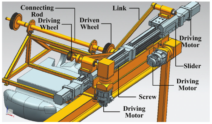
2.1. Robot Description
2.2. Dynamic Modeling
2.3. Problem Formulation
- A.
- The tracking errors of UBSHR’s active joints are defined as follows:in which and , and and are, respectively, the desired position and actual position for the hybrid robot’s ith slider and jth driving wheel. To guarantee the synchronization performance of UBSHR’s active joints, the tracking errors of the active joints should meet synchronous control theory as follows:
- B.
- The tracking errors of UBSHR’s end-effector are defined as follows:where , (i = 1, 2) and ,(i = 1, 2) denote the desired and actual pose. To improve the synchronization performance of UBSHR’s end-effector, the control objective can be described as follows:
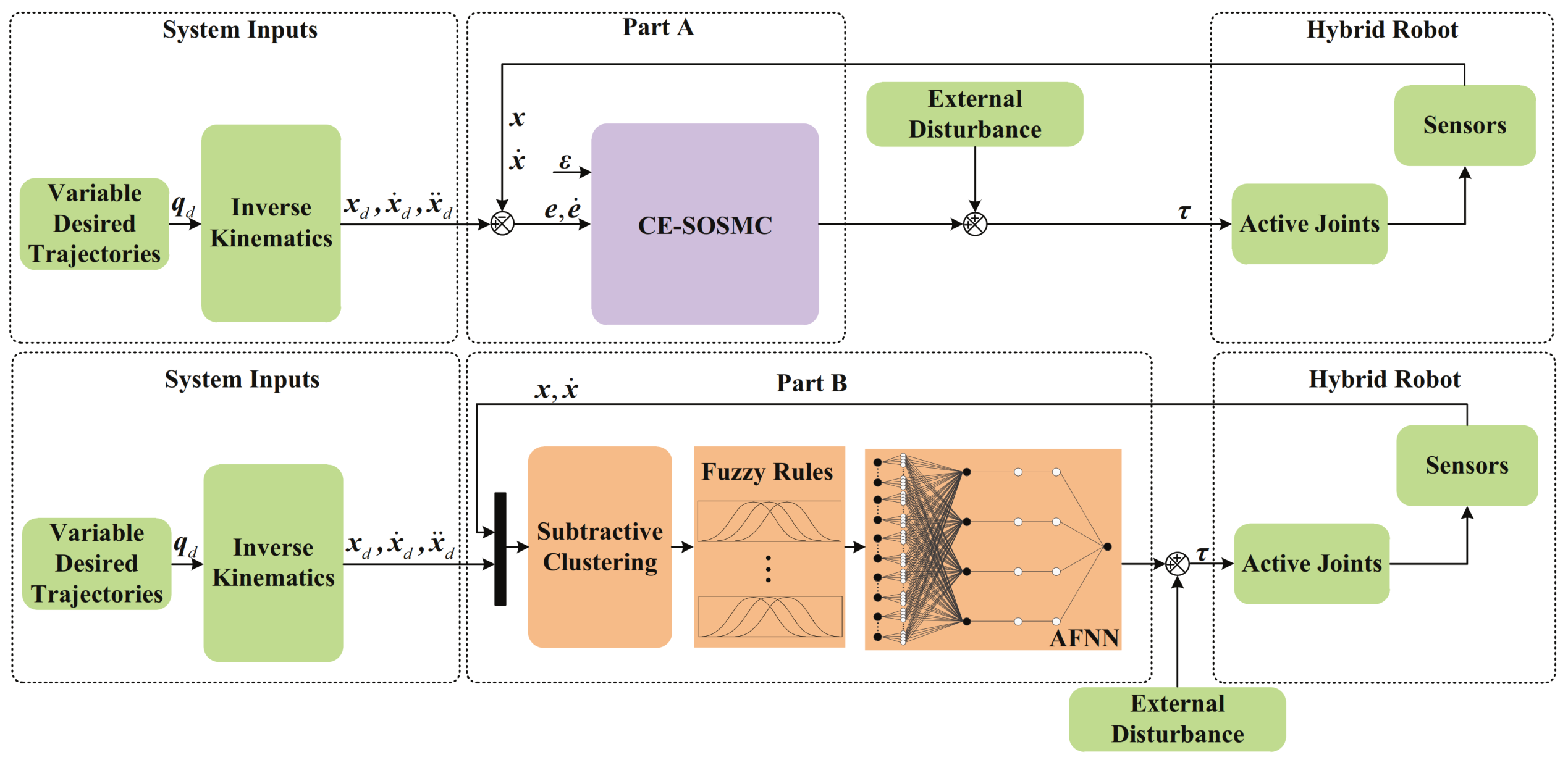
3. Controller Design
3.1. The Design of CE-SOSMC
3.2. The Design of SC-AFNN
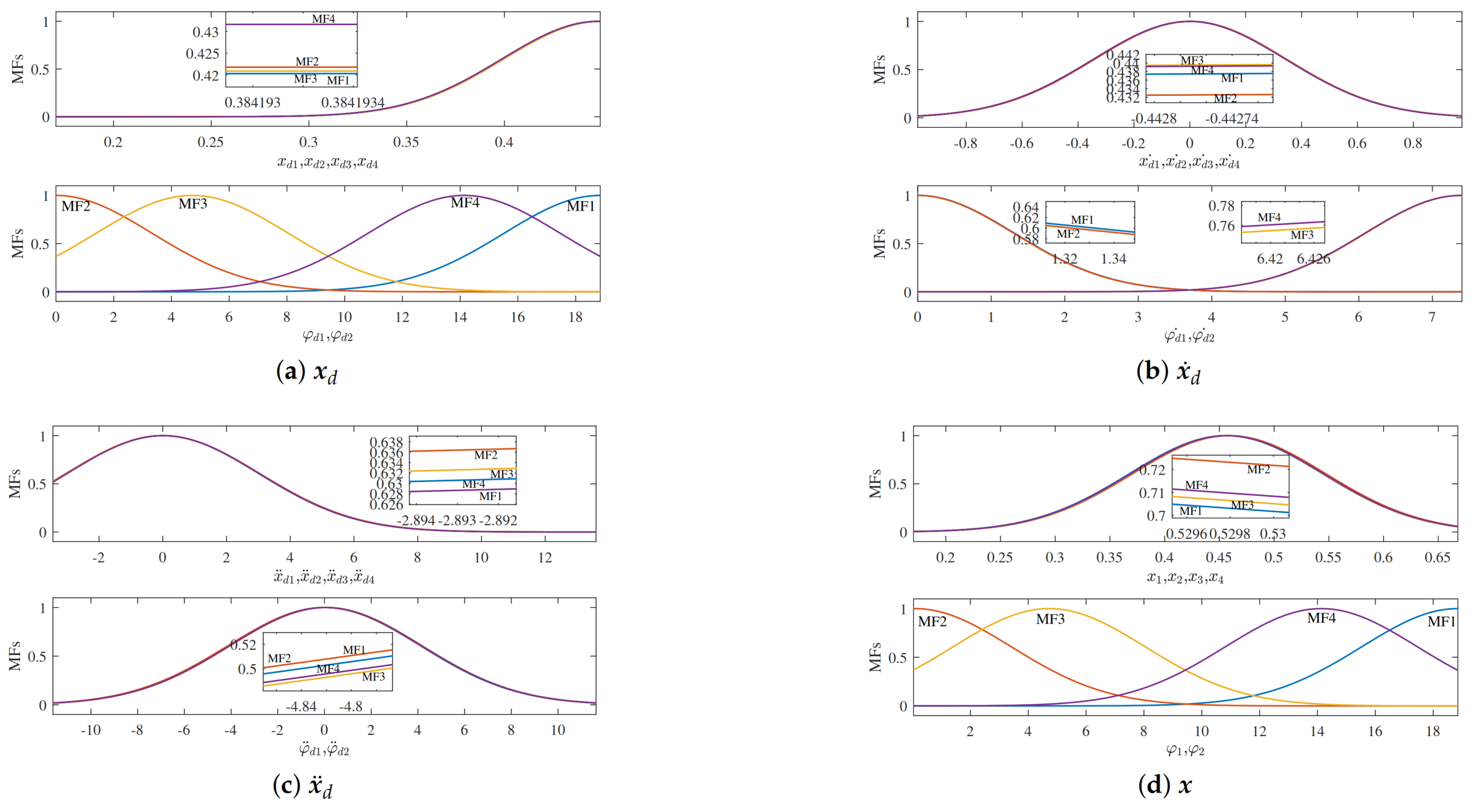
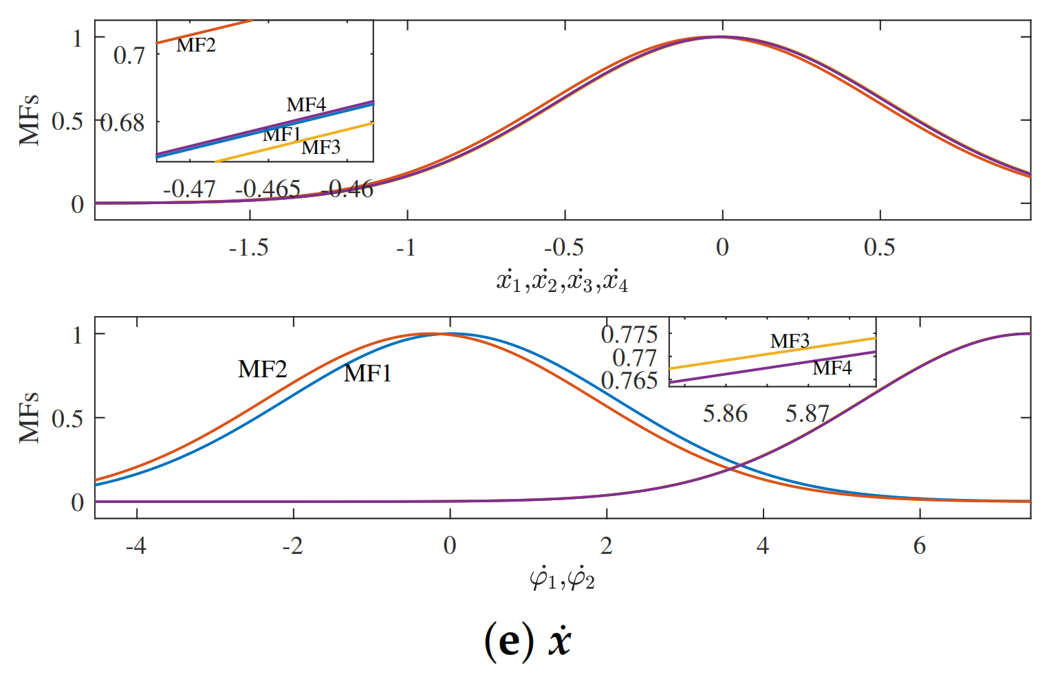
3.2.1. Fuzzy Rules Generation
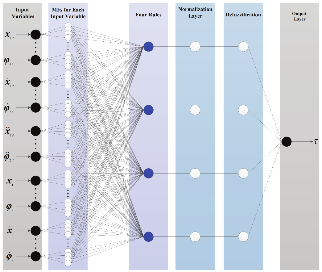
3.2.2. SC-AFNN Construction
- (1)
- ;
- (2)
- , when ;
- (3)
- , when .
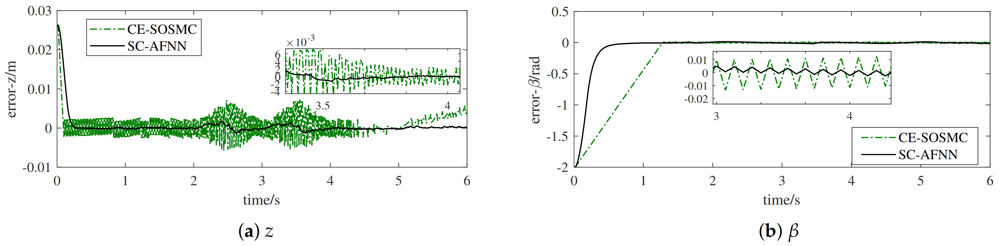
4. Simulations
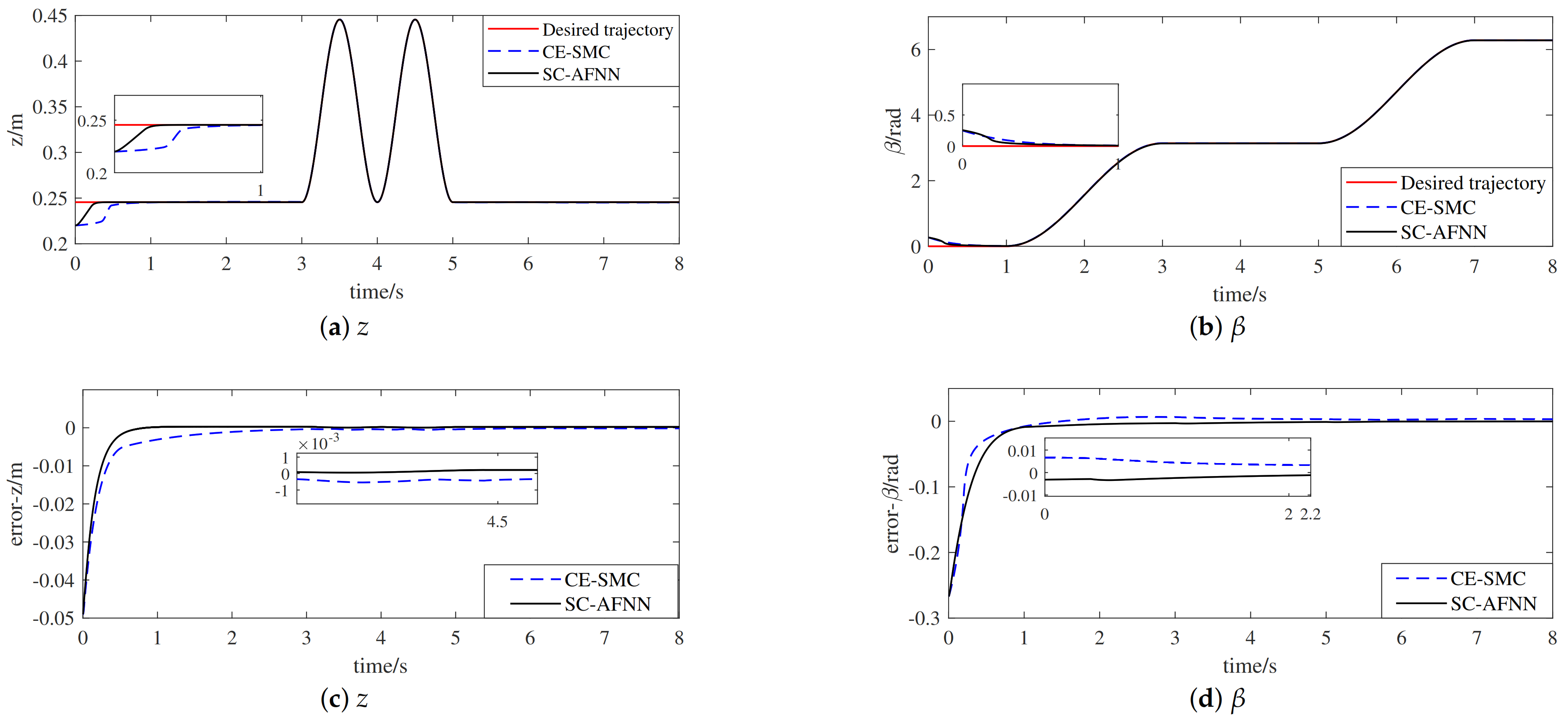
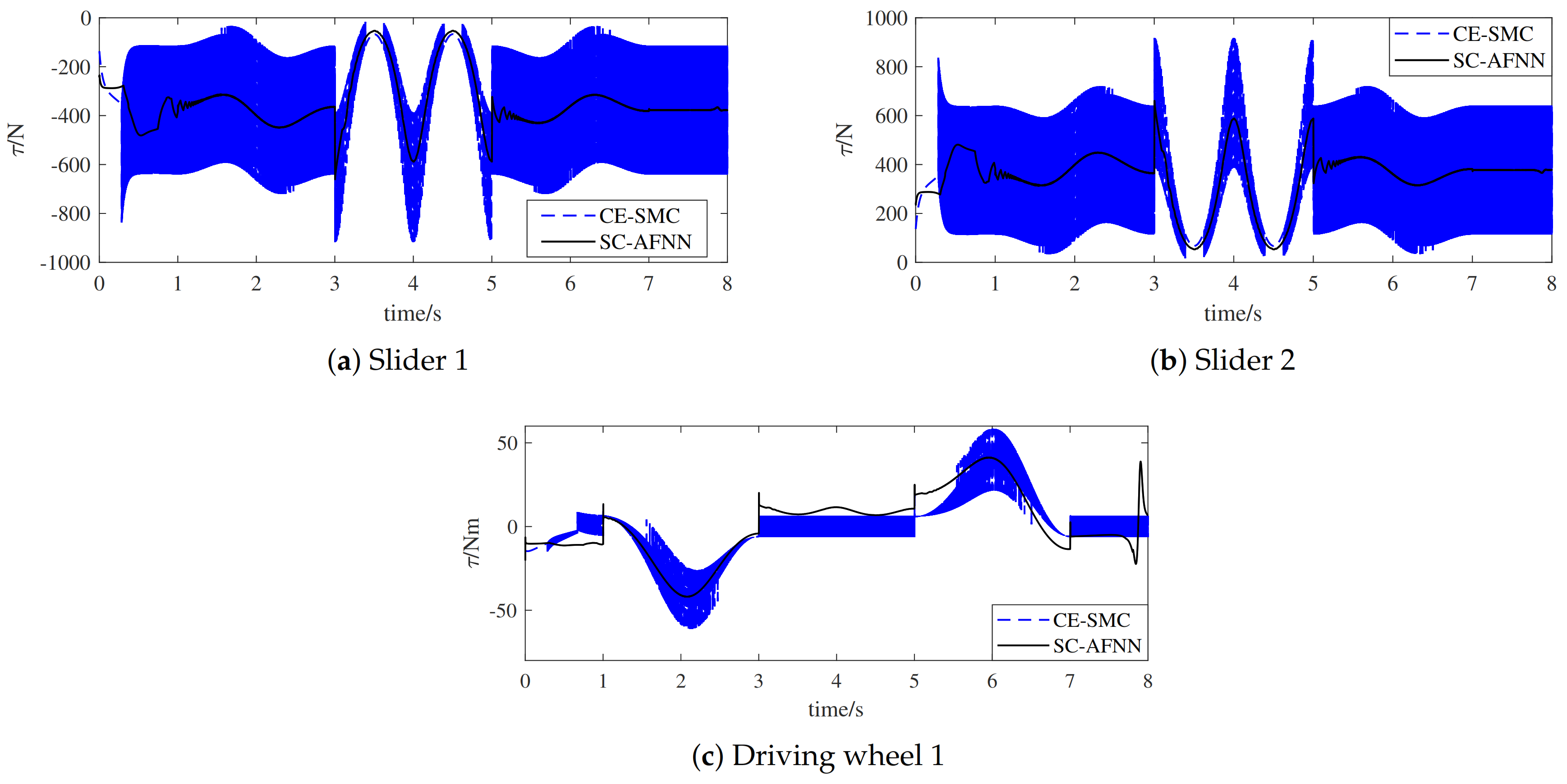
4.1. Case 1
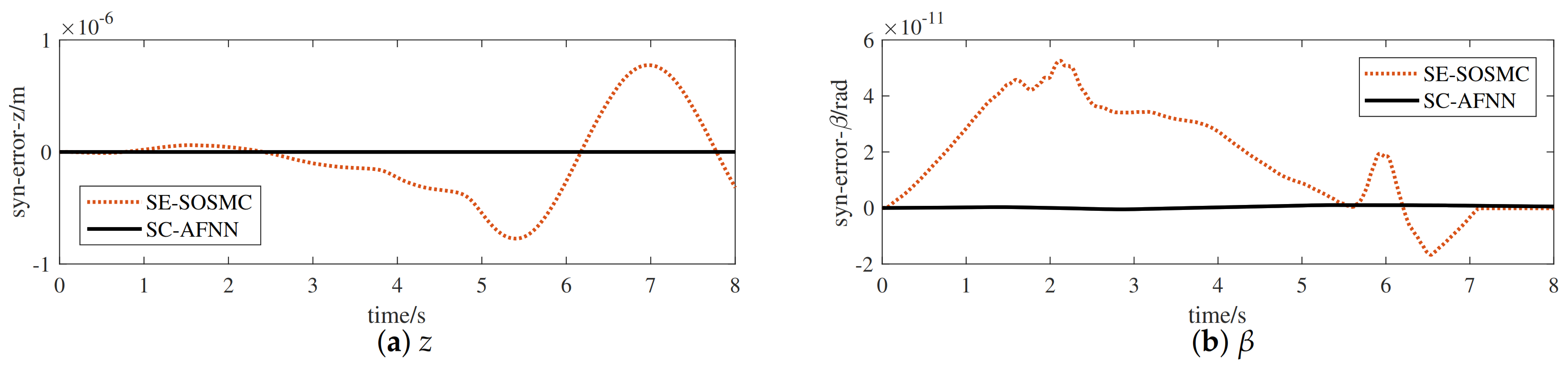
4.2. Case 2
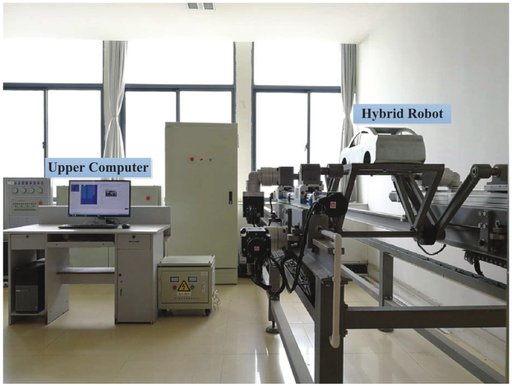
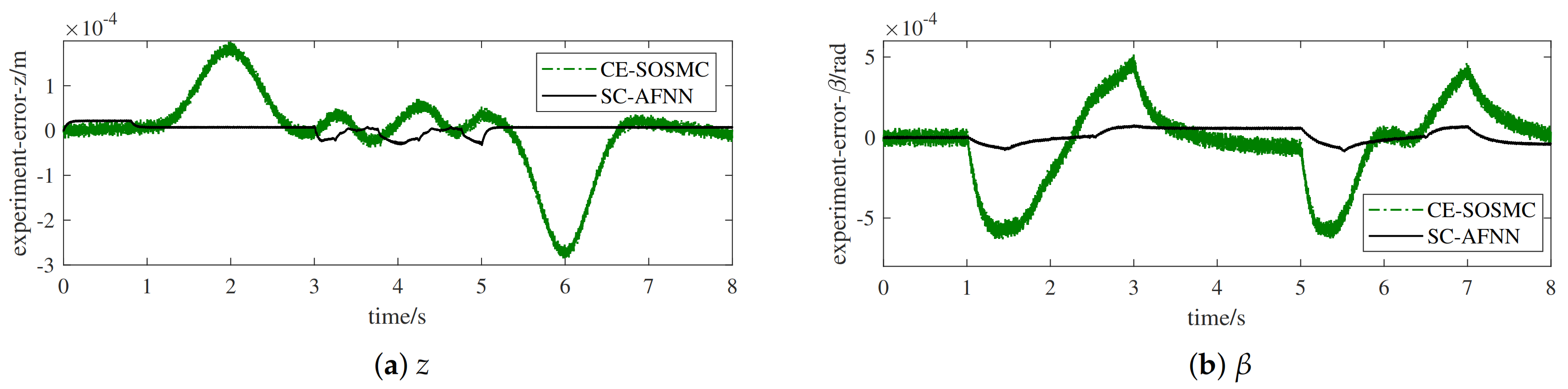
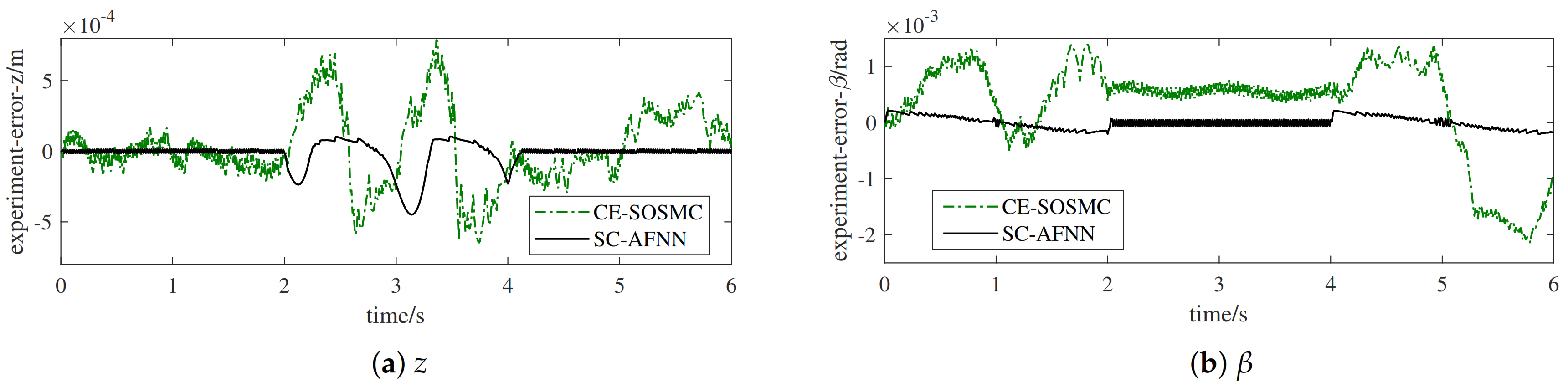
5. System Experiments
5.1. Control System Construction
5.2. Experimental Results
6. Conclusions
- (1)
- A novel composite error considering the synchronization errors and tracking errors of a UBSHR’s end-effector was defined. The CE-SOSMC was realized combined with the SOSMC method to solve the uncertainty problem and the synchronization problem simultaneously. The relationship of asymptotic convergence among the novel composite error, tracking errors, and synchronization errors was stated. Strict theoretical proof of the stability of CE-SOSMC was presented.
- (2)
- AFNN was introduced, and subtractive clustering in conjunction with evolutionary algorithm was applied for constructing fuzzy rule base with fewer rules automatically. Based on the fuzzy rule base, the SC-AFNN was further constructed to realize self-learning and self-adjusting of control rules and control parameters to conquer the flexible control problem of active adaption to different technological requirements without artificially adjusting the control parameters or switching the hardware system. The asymptotic stability of SC-AFNN was analyzed.
- (3)
- Compared with the existing synchronization error, the defined composite error could ensure the synchronization performance not only of active joints but also of the end-effector. Compared with the existing SMC method based on linear sliding mode surface, the presented SOSMC method possesses superiorities such as small chattering, non-singularity, and fast convergence rate. Compared with the existing control methods for systems with definite desired trajectories, the proposed SC-AFNN can track variational desired trajectories for hybrid robots.
- (4)
- Simulation and experimental researches were carried out to further validate the validity of the developed SC-AFNN method.
Author Contributions
Funding
Institutional Review Board Statement
Informed Consent Statement
Data Availability Statement
Conflicts of Interest
References
- Wu, J.; Chen, X.L.; Wang, L.P.; Liu, X.J. Dynamic load-carrying capacity of a novel redundantly actuated parallel conveyor. Nonlinear Dyn. 2014, 78, 241–250. [Google Scholar] [CrossRef]
- Xie, F.G.; Liu, X.J.; You, Z.; Wang, J.S. Type synthesis of 2T1R-type parallel kinematic mechanisms and the application in manufacturing. Robot. CIM-Int. Manuf. 2014, 30, 1–10. [Google Scholar] [CrossRef]
- Xu, F.X.; Liu, X.H.; Chen, W.; Zhou, C.; Cao, B.W. Improving handling stability performance of four-wheel steering vehicle based on the H2/H infinity robust control. Appl. Sci. 2019, 9, 857. [Google Scholar]
- Jagannathan, S.; Lewis, F.L. Robust backstepping control of robotic systems using neural networks. J. Intell. Robot. Syst. 1998, 23, 105–128. [Google Scholar] [CrossRef]
- Doan, Q.V.; Le, T.D.; Vo, A.T. Synchronization full-order terminal sliding mode control for an uncertain 3-DOF planar parallel robotic manipulator. Appl. Sci. 2019, 9, 1756. [Google Scholar] [CrossRef] [Green Version]
- Ding, S.H.; Liu, L.; Zheng, W.X. Sliding mode direct yaw-moment control design for in-wheel electric vehicles. IEEE Trans. Ind. Electron. 2017, 64, 6752–6762. [Google Scholar] [CrossRef]
- Wang, Y.Y.; Gu, L.Y.; Xu, Y.H.; Cao, X.X. Practical tracking control of robot manipulators with continuous fractional-order nonsingular terminal sliding mode. IEEE Trans. Ind. Electron. 2016, 63, 6194–6204. [Google Scholar] [CrossRef]
- Gao, G.Q.; Wu, X.T.; Cao, Y.Y.; Fang, Z.M. Synchronized sliding mode control of a hybrid mechanism for automobile electro-coating conveying. Electr. Mach. Control 2017, 21, 113–120. [Google Scholar]
- Gao, G.Q.; Zhang, M.C. Control of a novel hybrid conveying mechanism for electro-coating of automobile bodies. In Proceedings of the 2017 36th Chinese Control Conference, Dalian, China, 26–28 July 2017; pp. 4841–4846. [Google Scholar]
- Gao, G.Q.; Ye, M.Y.; Zhang, M.C. Synchronous robust sliding mode control of a parallel robot for automobile electro-coating conveying. IEEE Access 2019, 7, 85838–85847. [Google Scholar] [CrossRef]
- Feng, Y.; Han, X.; Wang, Y.; Yu, X. Second-order terminal sliding mode control of uncertain multivariable systems. Int. J. Control 2007, 80, 856–862. [Google Scholar] [CrossRef]
- Yi, S.C.; Zhai, J.Y. Adaptive second-order fast nonsingular terminal sliding mode control for robotic manipulators. ISA Trans. 2019, 90, 41–51. [Google Scholar] [CrossRef]
- Wang, Y.Y.; Zhu, K.W.; Yan, F.; Chen, B. Adaptive super-twisting nonsingular fast terminal sliding mode control for cable-driven manipulators using time-delay estimation. Adv. Eng. Softw. 2019, 128, 113–124. [Google Scholar] [CrossRef]
- Liang, Y.W.; Xu, S.D.; Liaw, D.C. A study of T-S model-based SMC scheme with application to robot control. IEEE Trans. Ind. Electron. 2008, 55, 3964–3971. [Google Scholar] [CrossRef]
- Lu, X.G.; Liu, M.; Liu, J.X. Design and optimization of interval type-2 fuzzy logic controller for delta parallel robot trajectory control. Int. J. Fuzzy Syst. 2017, 19, 120–206. [Google Scholar] [CrossRef]
- Xu, S.; Ou, Y.S.; Duan, J.H.; Wu, X.Y.; Feng, W.; Liu, M. Robot trajectory tracking control using learning from demonstration method. Neurocomputing 2019, 338, 249–261. [Google Scholar] [CrossRef]
- Moezi, S.A.; Rafeeyan, M.; Zakeri, E.; Zare, A. Simulation and experimental control of a 3-RPR parallel robot using optimal fuzzy controller and fast on/off solenoid valves based on the PWM wave. ISA Trans. 2016, 61, 265–286. [Google Scholar] [CrossRef]
- Rong, H.J.; Zhao, G.S. Direct adaptive neural control of nonlinear systems with extreme learning machine. Neural Comput. Appl. 2013, 22, 577–586. [Google Scholar] [CrossRef]
- Wu, Y.X.; Huang, R.; Li, X.; Liu, S. Adaptive neural network control of uncertain robotic manipulators with external disturbance and time-varying output constraints. Neurocomputing 2019, 323, 108–116. [Google Scholar] [CrossRef]
- Wu, L.L.; Zhao, P.Y.; Li, Y.Y.; Chen, Y.H. Optimal design of adaptive robust control for the delta robot with uncertainty: Fuzzy set-based approach. Appl. Sci. 2020, 10, 3472. [Google Scholar] [CrossRef]
- Yoo, B.K.; Ham, W.C. Adaptive control of robot manipulator using fuzzy compensator. IEEE Trans. Fuzzy Syst. 2000, 8, 186–199. [Google Scholar]
- Chiu, S.L. Fuzzy model identification based on cluster estimation. J. Intell. Robot. Syst. 1994, 2, 267–278. [Google Scholar] [CrossRef]
- ATakagi, T.; Sugeno, M. Fuzzy identification of systems and its applications to modeling and control. IEEE Trans. Syst. Man. Cybern. 1985, 15, 116–132. [Google Scholar] [CrossRef]
- Jang, J.S.R.; Sun, C.T.; Mizutani, E. Neuro-fuzzy and soft computing, a computational approach to learning and machine intelligence. IEEE Trans. Automat. Contr. 1997, 42, 1482–1484. [Google Scholar] [CrossRef]
- Gao, Y.; Er, M.J.; Yang, S. Adaptive control of robot manipulators using fuzzy neural networks. IEEE Trans. Ind. Electron. 2001, 48, 1274–1278. [Google Scholar]
- Gao, G.Q.; Chen, T.P.; Fang, Z.M. Dynamic modeling of a novel mechanism for automobile electro-coating conveying. J. Mech. Eng. 2016, 52, 8–16. [Google Scholar] [CrossRef]
- Shang, W.W.; Cong, S.; Zhang, Y.X.; Liang, Y.Y. Active joint synchronization control for a 2-DOF redundantly actuated parallel manipulator. IEEE Trans. Contr. Syst. Technol. 2009, 17, 416–423. [Google Scholar] [CrossRef]
- Yang, H.; Fu, Y.T.; Zhang, K.P.; Li, Z.Q. Speed tracking control using an ANFIS model for high-speed electric multiple unit. Control Eng. Pract. 2014, 23, 57–65. [Google Scholar] [CrossRef]
- Sun, Z.Q. Fuzzy-neural network and its application to system modeling and controls. J. Nanjing Univ. Chem. Technol. 2000, 22, 1–6. [Google Scholar]


| CE-SMC | SC-AFNN | ||
|---|---|---|---|
| Steady-state reaching time | z (s) | 1.24 | 0.38 |
| (s) | 1.26 | 1.04 | |
| Maximum tracking error | z ( m) | 5.18 | 2.20 |
| ( rad) | 6.55 | 3.08 |
| CE-SOSMC | SC-AFNN | ||
|---|---|---|---|
| Steady-state reaching time | z (s) | 2.08 | 0.26 |
| (s) | 1.36 | 0.72 | |
| Maximum tracking error | z ( m) | 72.05 | 14.45 |
| ( rad) | 14.01 | 7.88 | |
| RMSE | - | 0.54 | 0.30 |
| Maximum Tracking Error | RMSE | |||
|---|---|---|---|---|
| z ( m) | ( rad) | () | ||
| Desired trajectory 1 | CE-SOSMC | 28.64 | 63.15 | 2.60 |
| SC-AFNN | 3.05 | 8.65 | 0.47 | |
| Desired trajectory 2 | CE-SOSMC | 79.04 | 214.68 | 9.62 |
| SC-AFNN | 22.95 | 21.05 | 1.44 | |
Publisher’s Note: MDPI stays neutral with regard to jurisdictional claims in published maps and institutional affiliations. |
© 2021 by the authors. Licensee MDPI, Basel, Switzerland. This article is an open access article distributed under the terms and conditions of the Creative Commons Attribution (CC BY) license (http://creativecommons.org/licenses/by/4.0/).
Share and Cite
Qin, Q.; Gao, G. Composite Error-Based Intelligent Adaptive Sliding Mode Control for Uncertain Bilaterally Symmetrical Hybrid Robot with Variational Desired Trajectories. Appl. Sci. 2021, 11, 2613. https://0-doi-org.brum.beds.ac.uk/10.3390/app11062613
Qin Q, Gao G. Composite Error-Based Intelligent Adaptive Sliding Mode Control for Uncertain Bilaterally Symmetrical Hybrid Robot with Variational Desired Trajectories. Applied Sciences. 2021; 11(6):2613. https://0-doi-org.brum.beds.ac.uk/10.3390/app11062613
Chicago/Turabian StyleQin, Qiuyue, and Guoqin Gao. 2021. "Composite Error-Based Intelligent Adaptive Sliding Mode Control for Uncertain Bilaterally Symmetrical Hybrid Robot with Variational Desired Trajectories" Applied Sciences 11, no. 6: 2613. https://0-doi-org.brum.beds.ac.uk/10.3390/app11062613