Article

Fast, Accurate, and Reliable Detection of Damage in Aircraft Composites by Advanced Synergistic Infrared Thermography and Phased Array Techniques

by
Janardhan Padiyar M.
1,*,
Luca Zanotti Fragonara
1,*,
Ivan Petrunin
1,
Joao Raposo
1,
Antonios Tsourdos
1,
Iain Gray
1,
Spyridoyla Farmaki
2,
Dimitrios Exarchos
2,
Theodore E. Matikas
2 and
Konstantinos G. Dassios
2,3,*
1
School of Aerospace, Transport and Manufacturing, Cranfield University, Cranfield MK43 0AL, UK
2
Department of Materials Science & Engineering, University of Ioannina, 45110 Ioannina, Greece
3
Department of Chemical Engineering, University of Patras, 26504 Patras, Greece
*
Authors to whom correspondence should be addressed.
Submission received: 21 December 2020 / Revised: 28 January 2021 / Accepted: 5 February 2021 / Published: 19 March 2021
(This article belongs to the Special Issue Novel Approaches for Structural Health Monitoring II)

Abstract

:

Featured Application

The synergistic non-destructive method has been developed in the framework of automated inspections of aircraft composite structures.

Abstract

This paper presents an advanced methodology for the detection of damage in aircraft composite materials based on the sensor fusion of two image-based non-destructive evaluation techniques. Both of the techniques, phased-array ultrasonics and infra-red thermography, are benchmarked on an aircraft-grade painted composite material skin panel with stringers. The sensors systems for carrying out the inspections have been developed and miniaturized for being integrated on a vortex-robotic platform inspector, in the framework of a larger research initiative, the Horizon-2020 ‘CompInnova’ project.

1. Introduction

New-generation wide-body civilian aircrafts, such as Dreamliner Boeing 787 and Airbus A350 series, are manufactured from Carbon Fiber Reinforced Polymers (CFRPs) composites at a much higher percentage than compared to narrow-body aircrafts; relevant outer parts include their wing skins and fuselage skins. During aircraft service, thin-walled fuselage and wing skin surfaces are primarily prone to impact damages throughout their lifetime [1]. Impact damages can be caused by different threats, like human-induced defects, such as paint shop-prone tool drop, runway debris, ground hail, in-flight hail, and bird impacts. Impact damages are classified as Barely Visible Impact Damage (BVID) and Visible Impact Damage (VID), which may or may not cause full penetrations. Even though BVID’s cause considerable sub-surface damage, the identification of their location is particularly challenging under typical lighting conditions while using conventional manual visual Non-Destructive Testing (NDT) [2]. Nondestructive testing (NDT) methods are currently the most efficient means of aircraft inspection for identifying superficial, or otherwise undetectable by conventional visual inspection, damages and flaws [3]. Damage detection in aircraft is primarily linked to human lives and secondarily to equipment protection; hence, it must be efficient and reliable to the maximum degree possible in eliminating fatal consequences on the structure that can cause massive human life loss. To that end, an extreme effort is continuously invested towards the improvement of aircraft inspection worthiness and the development of reliable, automated, and synergistic techniques for capturing barely visible damage on aircraft. Currently, manual point-to-point inspection using conventional ultrasonic transducer and line-by-line Phased Array (PA) wheel probe [4] are used as a fundamental quantitative method, as per schedule-based maintenance for in-service inspections of composite skin surfaces. Such inspections are tactical and categorized in A-, C-, and D- checks, depending on the level of detail with respect to the aircraft age, hours in service, and the number of landing/take-off cycles. D-checks are the most thorough, involving a series of extremely detailed inspections of the fuselage skin and wing skin surfaces, requiring a minimum defect detectability of 6 × 6 mm, and carried out approximately every six years. For an aircraft, like an Airbus A320-200, a D-check can last up to six weeks and cost up to $1.8 million [5]. The automation of in-service NDT inspections can lead to reduced cost, by an increase in the availability of aircraft [6]. Consequently, there is both research and industrial interest in reducing the time and cost of aircraft maintenance, especially during C and D-checks maintenance, which involves detailed NDT inspection. The automation of slower point-to-point ultrasonic inspection has received considerable attention in the oil and gas sectors, for tank and pipe inspection; a substantial number of mature solutions based on magnetic adhesion mobile robots have been suggested. There are only a few automated solutions for in-service inspection of aircraft using conventional ultrasonic transducers, like the MAUS-V system based on Cartesian scanners and flexible tracks with suction pads as adhesion [7,8,9]. Moreover, the application of these scanners is limited by the length of the scanner arms and it needs to be moved and fixed sequentially to cover a large area, thus increasing the time that is required for inspection.
When compared to the point-to-point inspection method, full-field inspection NDT methods, such as infrared thermography (IRT) and shearography, have the inherent advantage of being non-contact and can scan large areas for defects in composites without the need for couplant agents. In recent years, full-field non-contact IRT has proved to be effective in detecting impact damages in aircraft CFRP composites, while new thermographic methodologies are constantly being improved at both the hardware level and post-processing stages to offer improved defect characterization [10,11,12,13,14,15]. IRT is rapid, contactless, and accurate, and it allows for automation for minimal operator involvement, hence offering the potential for minimization of human error. It operates on the principle of the thermo-mechanical coupling under the thermoelastic effect, wherein a change in the stress field in the material is related to a change in temperature [16]. Hence, collection and analysis, by passive IRT, of thermal energy dissipated from material under stress, provides information of its internal mechanical state [17]. For stress-free materials with pre-existing internal damages, such as the case of fuselage and wing skin of grounded aircraft undergoing inspection, active thermography is used in order to identify damage by capturing and analyzing the thermal energy dissipated from the surface while it is being thermally excited by an external thermal energy source. Independent of the technique used (active or passive IRT), the severer the damage in the material, the more intense the thermographic fingerprint of the damaged area, which appears on a thermogram as warmer or brighter color than pristine/unaffected areas. IRT is particularly applicable to composite materials, which are currently trending to replace more than 50% of the metallic aircraft fuselage and wing parts [18,19]. The technique has been highly successful in assessing the delamination damage typical of impact incidents that are found in aircraft-grade composites [20,21]. Most importantly, the technique is extremely versatile, as it can operate as stand-alone or complementary to other inspection methods [22,23]. The impact damage detectability of IRT depends on the thickness of the material, shape, dimensions, type of damage, and camera hardware sensitivity [24]. Although few previous studies have investigated combined the IRT and PA methods to characterize impact damages in CFRP composites [25,26,27,28], measurements in such studies have been performed with heavy equipment, which is unsuitable for deployment in the field and robotic applications or related to different engineering domains [29]. Moreover, automated in-service inspection of aircraft using combined PA and IRT methods have received little attention.
The limitations in available IRT techniques restricted their ability to perform fast and, at the same time, reliable quantitative inspections [30]. The recent development of an advanced variant of IRT, termed Pulsed Phase-informed Lock-in Thermography (PPI-LT), lifted this limitation [20]. As a two-step approach, PPI-LT relies on the fast initial assessment of defect presence, by pulsed-phase thermography (PPT) and the subsequent quantitative investigation of the area by lock-in thermography (LT). However, although PPI-LT can be particularly rapid and effective in imaging a wide material area (depending on sensor resolution and the instantaneous field of view-IFOV) from afar in a single acquisition and detecting the presence of defects therein, it is not equally powerful in the accurate quantitative assessment of the defects’ full geometrical and dilatational characteristics, under rapid wide-area mode. In other words, although rapid IRT could be used to scan a whole aircraft fuselage for damage in a cost-effective manner, the collected data would not contain sufficient defect sizing and depth profiling information for a reliable repair. Phased Array, on the other hand, is a slower and extremely accurate technique requiring contact-full and coupling; it is particularly powerful in achieving high-resolution three-dimensional (3D) geometrical assessment of superficial and subsurface defects. Although it would not cost-effectively scan a whole aircraft, it could provide extremely detailed information on size, shape, and depth profiling of a defect at a known fixed location.
The present paper reports the development of a novel synergistic strategy for the fast, accurate, and reliable detection, with full geometrical representation of damage in aircraft composites, by the sequential application of PPI-LT and PA. The strategy is suitable for automated inspection of impact damage in composite aircrafts and it consists of two sequential inspection steps: firstly, the entire composite structure of the aircraft is rapidly inspected with a newly-developed state-of-the-art, compact, and powerful IRT module operating under PPI-LT mode with custom control and analysis software (presented in [20]) mounted on a Vortex Robotic (VR)) platform to detect, identify, and mark all of the impact damage locations. In the next step, a newly developed PA module that explained in subsequent section is mounted on the VR platform and high-resolution scanning pursues on locations identified by IRT as a suspect of damage presence, for full dilatational and dimensional characterization of damage. The wheeled robot based on a negative pressure-based actuation method using EDF motors was developed for climbing and traversing over the surface of aircraft [31,32] with an NDT module as a payload. The strategy lifts the current trade-off between speed and reliability of aircraft inspection by utilizing IRT as a fast initial indicator of damage presence, over which thorough inspection by PA may ensue. Hence, by taking advantage of the wide non-contact area and reliability of thermal imaging, it is no more required to scan the complete structure by detailed and time-consuming PA inspection, but only damage-suspect areas. This maximizes the efficiency of the inspection while proving to be highly cost-effective. The strategy and individual VRP-mountable synergistic modules form part of a revolutionary fully automated NDT inspection solution offering an unprecedented reduction of aircraft inspection time and cost and increase of defect detection reliability in commercial aircraft, in the context of an ongoing Future and Emerging Technologies (FET) European Commission Horizon 2020 research project [33,34].

2. Material and Methods

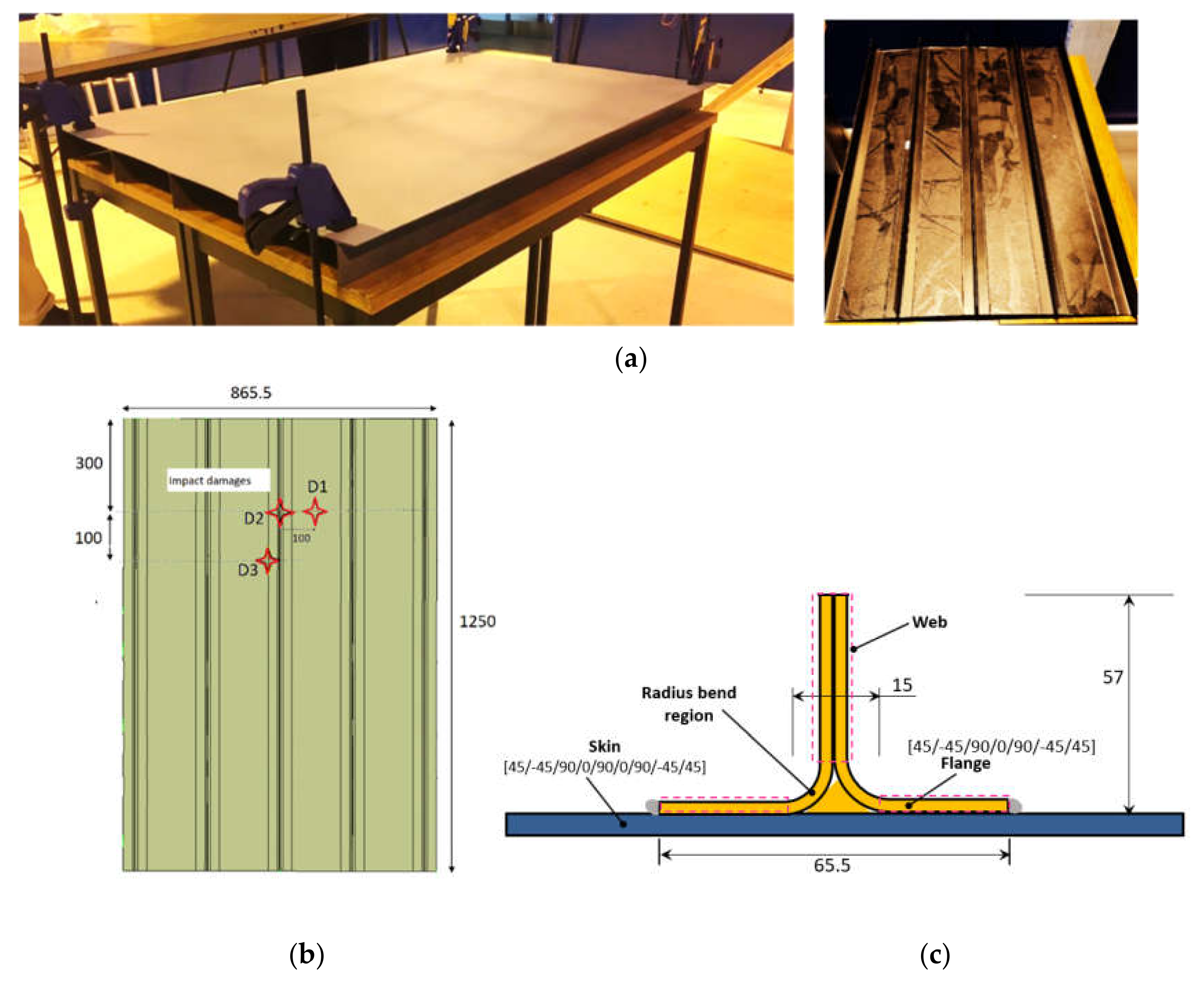
2.1. Description of Materials and Specimens

The benchmarking of the synergistic PLI-LT/PA strategy was performed on aircraft-grade composite of different scales: initially on composite coupons of material UD pre-preg IMS-977-2 having layup of [45/−45/90/0/90/0/90/−45/45] and [45/−45/90/0/90/0/90/−45/45]2s and two flat laminates, and subsequently one curved laminate of same material as coupons and [45/−45/90/0/90/0/90/−45/45] layup. All of the laminates carried artificially BVID inflicted using a gas gun; the coupons carried BVID of variable dimensions due to the varying of the impact energies in an impact drop tower.
A stringer stiffened composite panel representative of the aircraft structure with dimensions of 1250 x 865.5 mm2 was prepared by stacking carbon-fiber prepreg DeltaTech T800S-150-DT120-35 with the symmetric [45/−45/90/0/90/0/90/−45/45] sequence; T-shape stringer stacking followed a [45/−45/90/0/90/−45/45] sequence was also manufactured. The schematic of Figure 1 presents the skin with attached stringer geometry, dimensions, and layup sequence. A copper-mesh layer was integrated in the stacking sequence to account for the lighting-strike protection system typical of commercial and military aircraft. The mesh, DEXMET 2Cu6-100FA, an expanded film of copper of a thickness of 0.051 mm and a cavity area of 76%, Long Way Measurement (LWM) of 2.54 mm, was the second ply in the laminate and it resided just below the top GFRP ply, at an approximate depth of 0.18 mm. Autoclave co-curing at 120 °C and 6 bars of pressure for 90 min., of the skin with attached stringers pursued, as per prepreg manufacturer specifications. Finally, the external surface of the panel was finished using the same aircraft-grade paint as the coupons. Three barely visible impact damages, termed D1, D2, and D3, were inflicted equally in number locations on the panel while using a gas gun; the schematic of Figure 1b shows their exact positions. D1 was inflicted on the skin region between stringers, D2 on a skin region just above a stringer foot bond area, and D3 on a skin region just above a stringer. Neither damages produced observable surface dents on the skin. Figure 1c shows a view of the panel’s rear face with stringers. Thermographic and ultrasonic inspection was performed with the IRT and PA modules that were mounted on prototype VR platforms to perform automated operation on this panel.

2.2. Experimental Setup Details—IRT

A state-of-the-art IRT module was developed and presented previously to account for extreme compactness and lightweight required for automated inspection on a VR platform [20]. In brief, the module consisted of two main parts: a microbolometer shutterless longwave infrared (LWIR) sensor, the spectral response of 7–14 µm, made of resistive amorphous silicon in aluminum housing that was equipped with a lens with a ratio of F/1.25, a focal length of 16.7 mm, wide field of view of 37.5°, and manual focus end piece, and a 300 W halogen lamp excitation source housed in a bell-shaped reflector with IR-filtering eyepiece to block IR reflections from hitting back to the sensor. The sensor offered advanced technical specifications, including thermal sensitivity (noise equivalent temperature difference, NETD) of less than 50 mK, resolution of 640 × 480 pixel, time-to-image of less than 1 s, and a frame capture rate adjustable between 9 Hz and 120 Hz.
The module was assembled by mounting the sensor and source on an autoclave-cured carbon fiber reinforced polymer (CFRP) plate. Figure 2a presents the module face, while Figure 2b demonstrates it mounted on the VR platform. The lens protruded from the plate by 20 mm while the lamp position in the reflector was recessed by 30 mm from the plate. The dimensions of the sensor and the complete module were 30 × 30 × 45 mm3 and 200 × 150 × 100 mm3, respectively. The optimization of the module height (distance of plate from the surface under examination) was performed under the condition of IFOV maximization while maintaining full thermographic information from the surface. The IFOV should be maximum for the corresponding scanned area to be as wide as possible, which minimizes the acquisition timescale requirement for the whole aircraft structure. Based on this, a module height of 400 mm from the surface provided a optimal field of view of 320 × 240 mm2. Indicatively, a much smaller field-of-view of 200 × 150 mm2 was measured at a module eight of 250 mm. Most importantly, the respective weights of sensor and complete module, 70 g and 407 g, are indicative of the compactness and maneuverability offered, which makes them ideal for the targeted field application and mounting method. Prior to the start of IRT inspection, the lens end piece was focused on the surface under examination and a sensor calibration procedure, where the following involved exposure of the sensor to uniformly hot and cold surfaces, in sequence. During the initial phase of PPI-LT, the lock-in frequency was selected after the identification of the thermogram associated with the maximum contrast among those that were collected at various frequencies. In the second step, the surface within the field of view was analyzed in detail by locking thermography at the selected frequency.
A dedicated Graphical User Interface (GUI) was developed to allow for sensor control, thermogram acquisition, analysis, and communication with the VR platforms. The software offered functions for adjusting capture frame rate, calibrating, commencing, and ending PPI-LT, displaying live thermographic information, recording, analyzing, and post-processing thermograms, automatically detecting defects by pattern recognition, performing non-uniformity corrections of the IR sensor, thermogram analysis and post-processing, and many others. All of the thermograms were analyzed in the phase domain.

2.3. Experimental Setup and PA Module

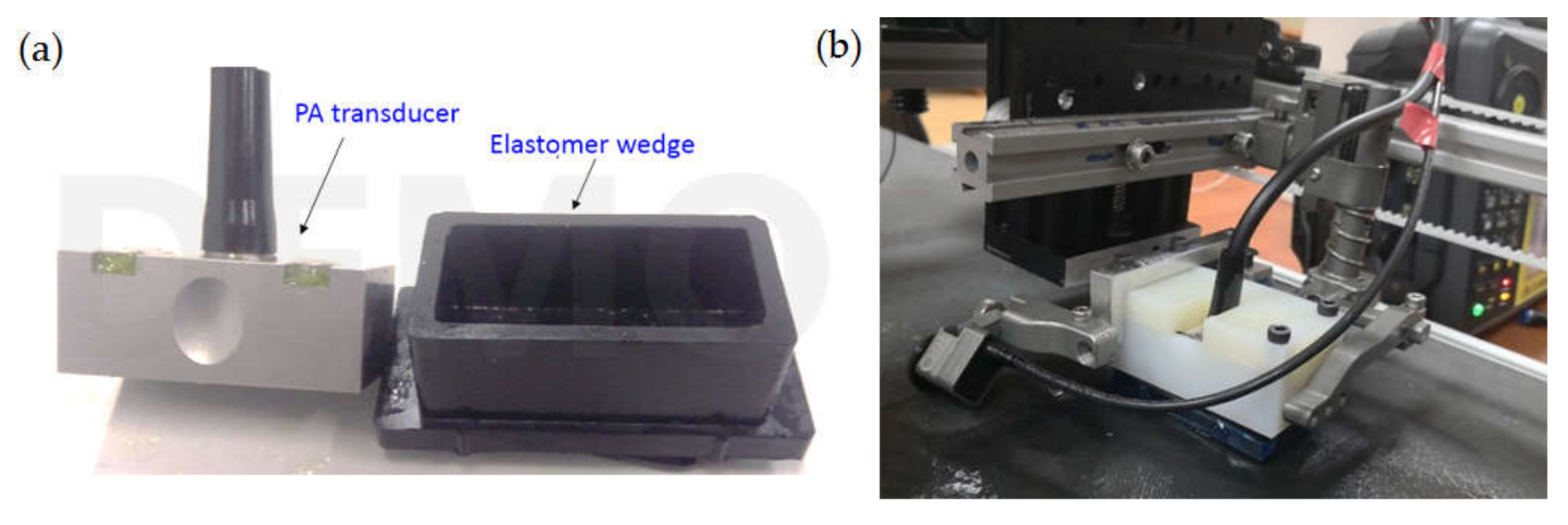
2.3.1. PA Module Development

In general, the ultrasonic NDT module for automated scanning of a curved structure consists of a suitable ultrasonic transducer, with an efficient wedge to transfer ultrasonic wave from the transducer into the specimen material, a positioning fixture with a different degree of freedom suitable for either flat and curved surface, an encoder for capturing position data, highly efficient couplant distribution system and control system for interfacing between the scanner, and the data acquisition hardware for data storage and scanning control. Because of the technical requirements of the vortex robot design [31,32], the NDT module payload was limited 1 kg along with a restriction of relying on any free-flowing water or a local immersion coupling techniques in proximity of the robot to avoid potential sparking of the EDF motor or electronics damage. These requirements invalidate the use of different types of local immersion based wedges, including membrane based wedges. Based on these requirements, and a suitable PA module was designed and developed, as discussed in the following subsections.

PA Transducer

A linear array 10 MHz 64 element transducer with −6 dB level bandwidth between 7.8 and 11 MHz was used for the inspection. The fusleage skin thickness is between 1 to 3 mm. Inspection with a higher frequency transducer gives a higher axial resolution in the thickness direction of the material being inspected, but the corresponding signal to noise ratio is lower, due to higher structural noise and higher sensitivity to the surface when compared to a lower frequency transducer [21].

Wedge

An ultrasonic inspection typically requires the use of free-flowing water, a film of water, local immersion, or ultrasonic gel as a coupling medium between the transducer and surface under inspection. The restriction of existing methods of couplant usage by VR platform requirements was addressed by developing a new wedge of elastomer material that is similar to a wheel probe roller material [4], which has low attenuation, low acoustic impedance, and lower couplant requirements. The wedge thickness was optimized for a 10 MHz PA transducer that is based on ultrasonic beam characteristics, near-field length, and attenuation in the elastomer material. The elastomer wedge and transducer are enclosed in a light-weight nylon holder for the PA transducer-wedge assembly, as shown in Figure 3. A miniature encoder for capturing positional data is also clamped to the nylon holder.

Mist Couplant Delivery

During automated phased array inspection, the prerequisite requirement for reliable ultrasonic data collection is to ensure that the wedge is in contact with the surface along with uniform couplant distribution on the surface. The spray of water is a sufficient form of couplant for the elastomer wedge on a flat surface. However, the fuselage of the aircraft is curved, smooth, and painted, which results in any sprayed water droplets to coalesce and drip down the surface. It was seen experimentally that fine mist of water instead of spray using a appropriate nozzle ensures uniform distribution of mist on the surface under any orientation during inspection. A self-priming micro-diaphragm pump was used to generate a fine mist of water using a nozzle with an orifice of 0.1 mm instead of spray during the inspection. The pump outlet was controlled by a flow control valve through a TEE connector to reduce the flow rate and provide a 50 PSI constant pressure water for generating a fine mist. The other end of TEE was connected to a hose to recirculate the extra water back to the water reservoir. It was observed that fine mist adheres to the painted surface, irrespective of the surface’s orientation. The mist is uniformly distributed with less than 2 mL of water consumed, for a scan area of the size of a coupon 150 × 100 mm, thus minimizing the amount of couplant water near the VR.

Positioning Device

For maximum signal amplitude during the reception, the PA transducer-wedge assembly must maintain both normal incidence to the surface and constant contact between the wedge and inspected surface, throughout the scan in all orientations (vertical, horizontal, and inverted). This requirement is achieved by the customization of a spring-loaded positioning fixture with three degrees of freedom (one vertical and two rotations) suitable for flat and curved surfaces. This gimbaled probe holder also ensures adherence in the case of the inspection of curved surfaces (e.g., aircraft fuselage).

2.3.2. PA Inspection Procedure

The experimental inspection procedure consisted of an initial benchmarking of NDT characterization of low-velocity impact damages on composite coupons of two different thicknesses and laminates. The PA hardware consisted of a multi-channel pulse-receiver Sonatest (16:64) VEO+ series with simultaneous emission and reception along each channel and 16 active channels. This pulse-receiver is operated under a normal incidence pulse-echo configuration to excite the 10 MHz 64 element linear array PA transducer with a square pulse of a maximum permissible voltage of 70 V with eight active apertures. Prior to PA scanning, the hardware is pre-loaded with a specific PA configuration file, having information regarding material velocity, time-gain compensation, and scanning parameters. The receiver gain and range are set, as per the thickness of the component under inspection. These scans were performed by mounting the PA module on a simple X-Y-Z manipulator.

2.3.3. PA Inspection Data Post-Processing

During measurements, full waveform ultrasonic data were recorded and stored at 125 MHz sampling frequency. The proprietary raw data file format of PA data was converted to neutral Comma Separated Values (CSV) format and an initial auto error-check was carried out for any missing A-scans in the data, due to an error in the encoder movement during scanning. Impact damage affects both the amplitude of ultrasonic reflections and their time of arrival from the damaged region. The Time-of-Flight (ToF) C-scan was generated with an ad hoc software suite in order to show the lateral extent of the impact damage. Before generating the C-scan image, each A-scans requires signal amplification, known as time-gain compensation, time-domain alignment of the A-scans, followed by ToF extraction of the first maximum peak after the front surface echo. Hilbert transform was used to find the maximum echo after the dead-zone, and maximum echo is time-tracked for the damage-depth information based on a specified threshold in each A-scan [35]. Furthermore, time-domain alignment of all A-scans is initially essential to account for delays in the arrival of the ultrasonic reflection from the top surface of the specimen due to composite surface flatness variations. This correction avoids C-scans images with false positives depth scale. It was observed that the time-domain alignment of all A-scans during post-processing is better than the digital floating-gate manually set in the PA hardware to track the front surface echo during data acquisition. The ImageJ software measures the damage area from the processed C-scan images.

3. Results and Discussion

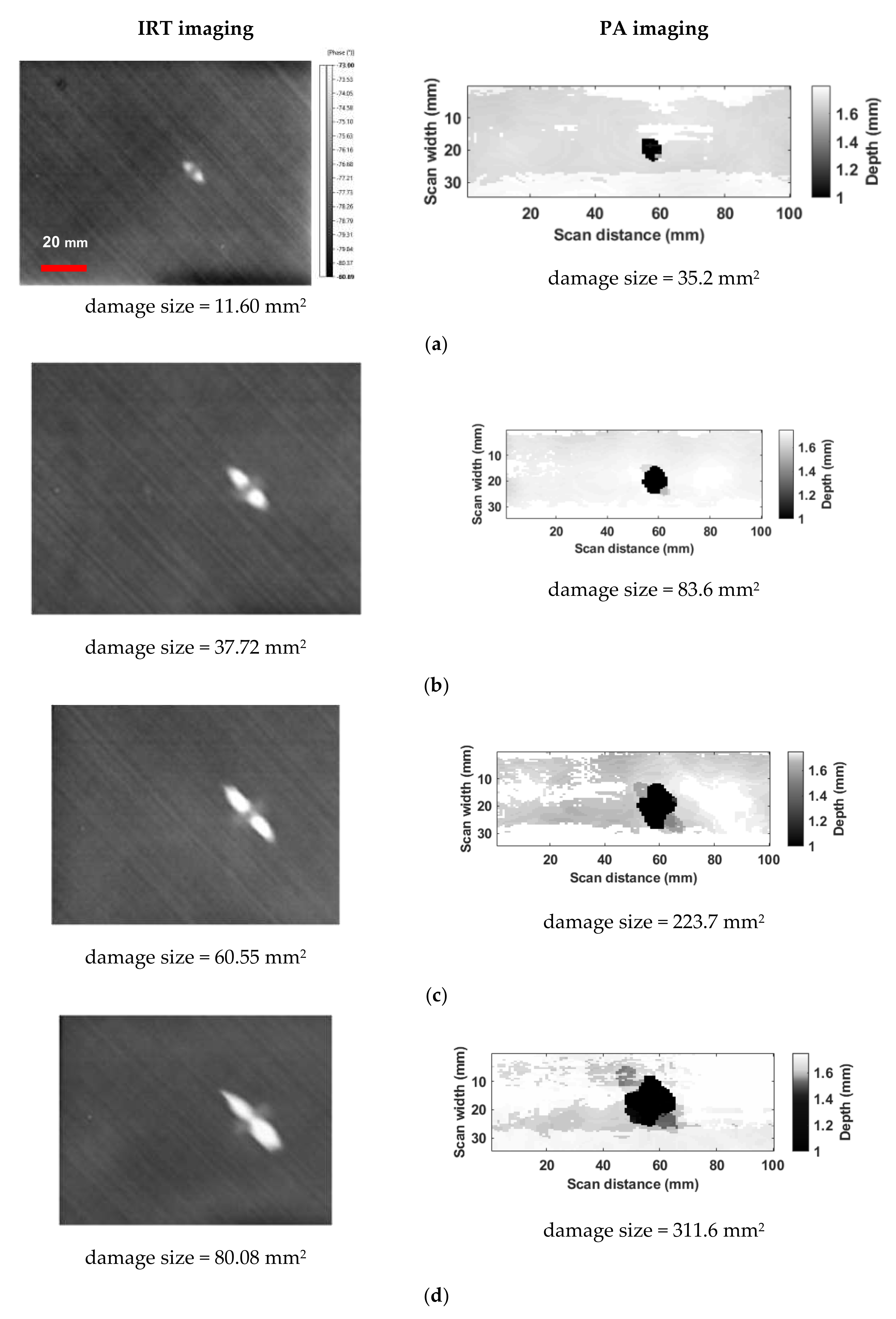
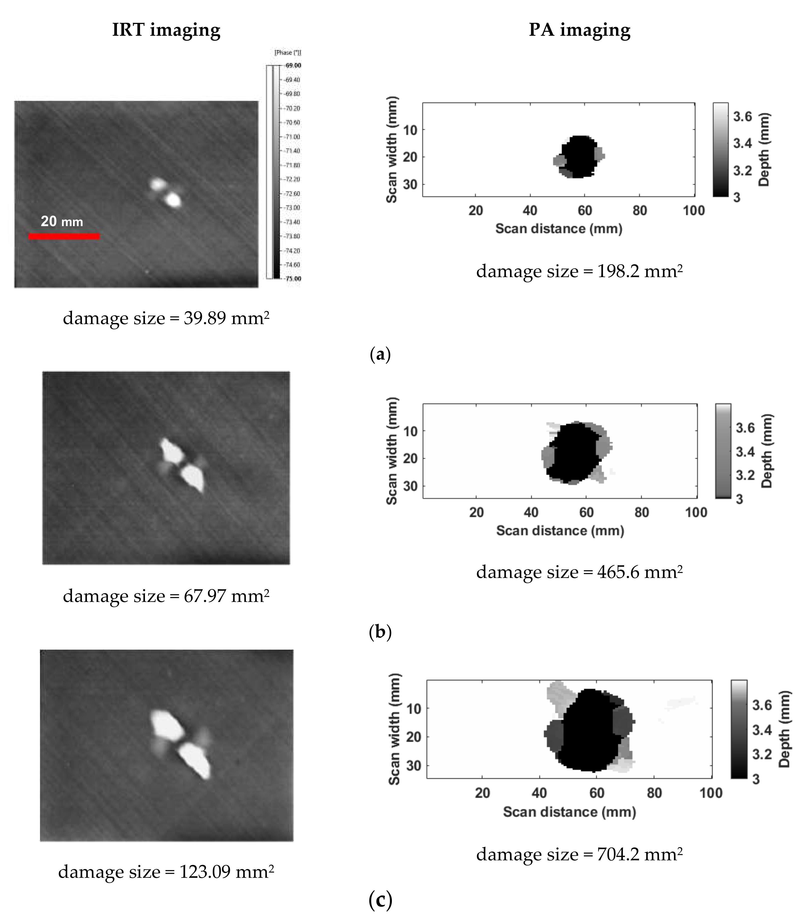
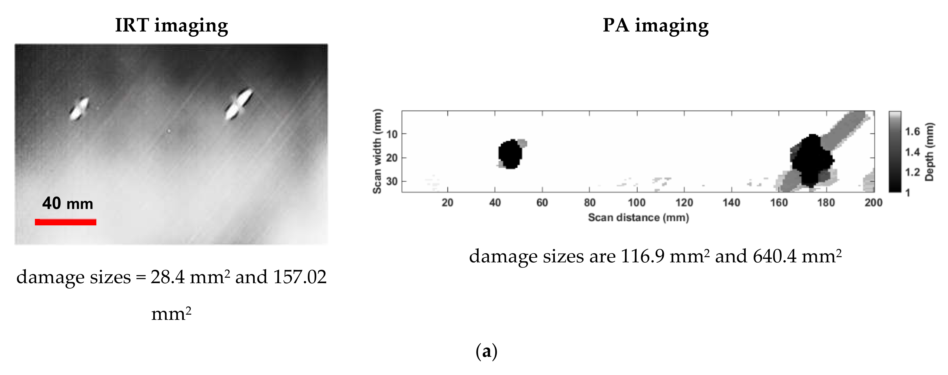
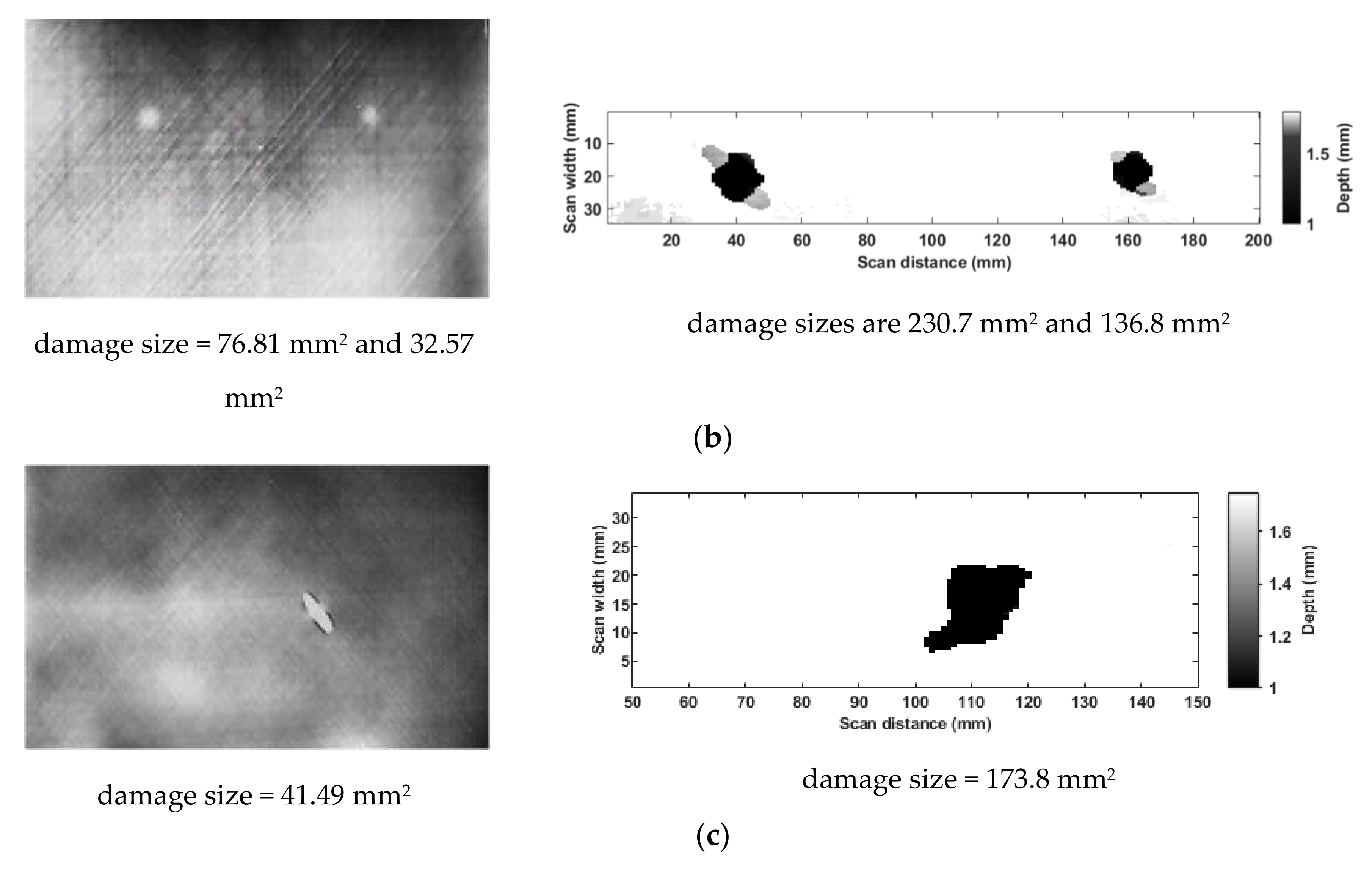
3.1. Results of Manual IRT and PA Inspection on Coupons and Laminates

The synergistic PPI-LT/PA strategy minimizes the timescale that is required for reliable aircraft inspection by the preferential application of PA inspection, for thorough damage characterization, only to areas previously identified with damage presence by rapid wide-area IRT. Under this concept, PPI-LT and PA were used in succession to fast scan the composite and indicate areas that require further PA inspection. Figure 4, Figure 5 and Figure 6 report pairs of successive results of IRT-identified and PA-quantified damaged areas on 9- and 18-layer composite coupons and laminates, respectively, for different levels of impact energy. All of the thermograms (figures on the left-hand side) are in the phase domain and they include relevant length and phase scale bars; the bars in the first thermogram of each subset are common for the rest, in the same subset. The C-scan image’s horizontal scale represents the scan-axis, along which the C-scans were recorded with a resolution of 1 mm. The vertical scale represents the index resolution of 0.6 mm, which is also the pitch between the PA transducer elements. The grayscale color bar that is shown in the C-scan images represents ToF of the maximum peak echo of the received signal from the material‘s entire thickness except the dead-zone. The inverse ‘gray’ color-pallet with custom color-bar facilitates straightforward damage discrimination using an image processing routine in ‘ImageJ’ software. The calculated damage area provides a close estimation of the extent of the damage. Figure 4 compares the infrared thermograms and PA images from nine-layer composite coupons impacted with energies of 2.5 J (a), 4 J (b), 8 J (c), and 12 J (d). IRT and by PA also capture damage in composite coupons of 18-layers in Figure 5, for impact energies of 8 J (a), 12 J (b), and 20 J (c). In Figure 6, thermographic and subsequent PA investigation is presented for composite laminates that are impacted with different energies.
By observation of the thermographic results that are presented in Figure 4, Figure 5 and Figure 6, it is concluded that damage is captured with exceptional precision by the developed PPI-LT approach and sensor in all types of specimens. It is interesting to note that the technique not only assesses the presence of damage, but it can represent its main geometrical features, such as shape and orientation, as documented by the high contrast area corresponding to damage in −45° laminas in the thermograms. In certain cases, such as Figure 5b,c, the barely visible dent produced at the site of impaction is also visible (dark circular mark at the damage center). The increasing extent of damage with increasing impact energy is efficiently assessed by IRT. Hence, it entails that the developed PPI-LT approach and sensor can not only identify damage presence, but can also provide its basic dilatational characteristics.
Observing PA C-scan images of impact damages that are presented in Figure 4, Figure 5 and Figure 6, the following general observations can be derived: the impact damage size increases with impact energy, and damage tends to propagate along the 45° to fiber direction. In all coupons, the impact damage shows large sub-surface damage, with little or no external indication of the impact. Hence, it is vital to carry out detailed NDT inspections on the composite aircraft’s external surface during heavy maintenance. In all coupons and laminates, IRT imaging shows the good detectability of damage, but the damage area is consistently smaller in size when compared to C-scan. This is because, under the rapid mode requirement of the target application, IRT is used as a fast initial indicator of damage presence; hence, PPI-LT does not offer the resolution that is required for performing full damage analysis. On the other hand, low-speed selective PA on IRT-identified areas only offers the added high-resolution feature that is required for this. In higher thickness coupons, IR thermograms exhibit lower sensitivity on impact damage, even though PA detects large sub-surface damage. These results indicate the importance of impact damage detection and the need for 100% inspection. However, adopting the proposed inspection strategy, 100% detailed inspection of the whole structure using thorough, but also time-consuming, PA can be avoided. This is also brought forward by comparison of the timescales that are required for the full acquisition of a specified surface area, by the two techniques. While PPI-LT is imaging, the whole 320 × 240 mm2 area under the optimal IFOV is done in approximately 60 s, the corresponding timescale requirement for full PA acquisition of the same surface must be carried out using the unidirectional raster scan approach of about ten line-scans taking about 4 min. with added complexity of VR forward and backward locomotion. This observation highlights the added value of the synergistic approach towards the rapid, but, at the same time, accurate, damage detection in aircraft composites.

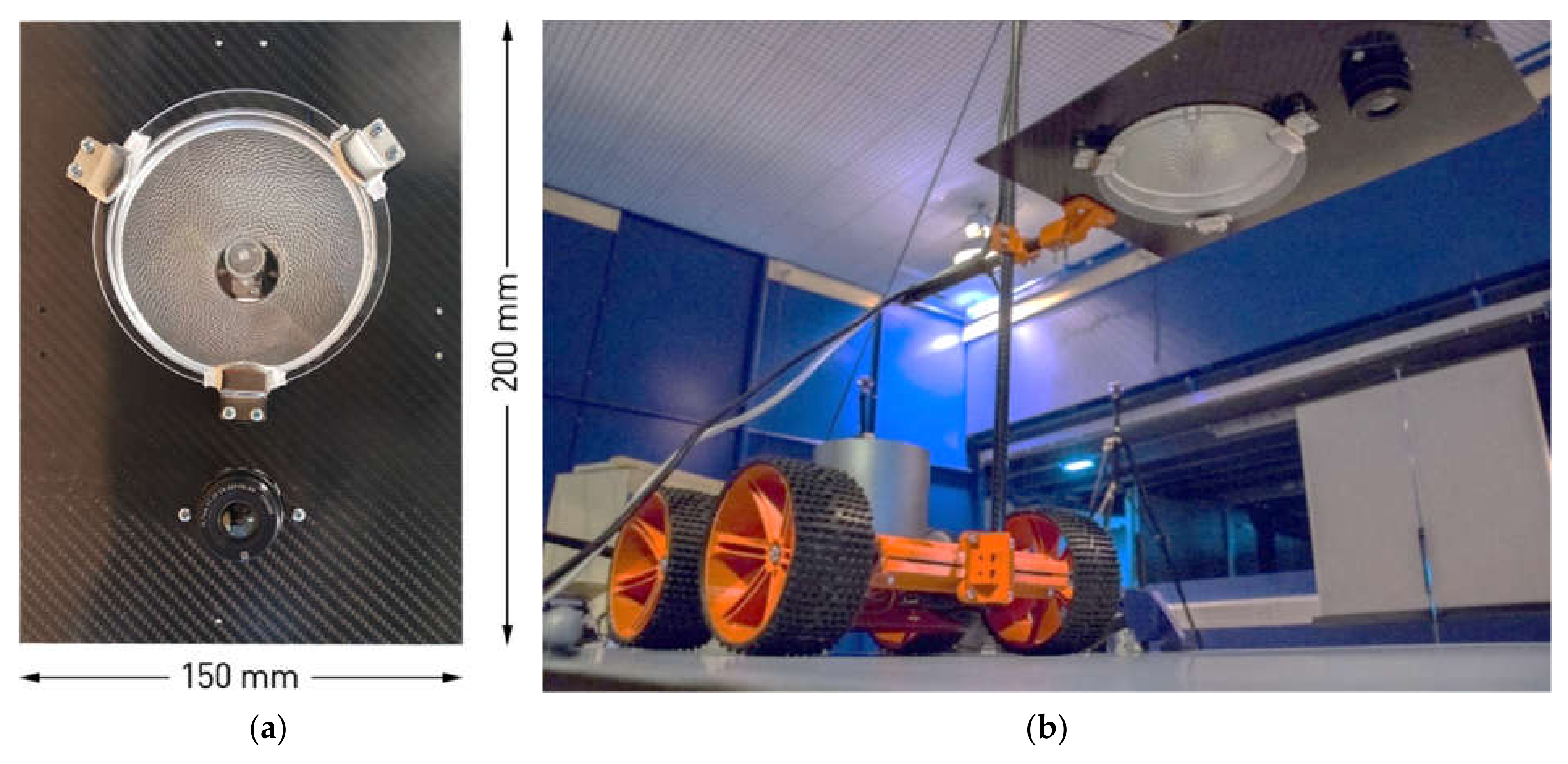
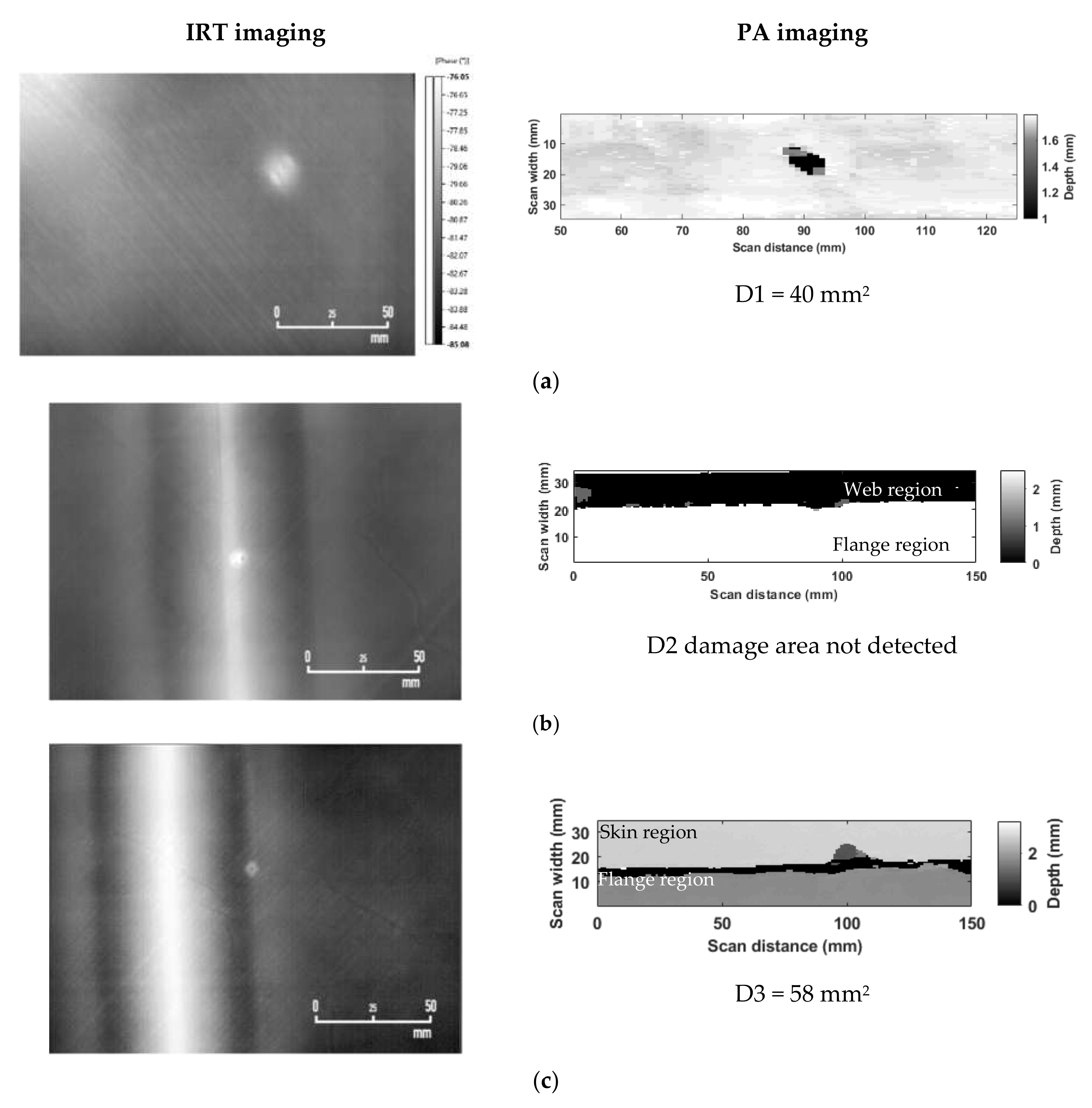
3.2. Automated IRT and PA Inspection on Stiffened Panel

The stiffened panel was initially scanned by PPI-LT for rapid wide-area identification of damage location, after which PA inspection was pursued. This primmer task was undertaken with the IRT module that was integrated on the VRP, as seen in Figure 2b as a lab-scale demonstration of the envisioned fully automated NDT solution for rapid and reliable damage inspection in aircraft. The thermographic assessment of damage locations is presented in the left-hand side part of Figure 7. Therein, all three impact damages of the stiffened panel are observed to have been positively identified by the PPI-LT technique. Moreover, the extent of damage appears to be greater in the skin region D1, in the absence of back face stiffening, and smaller in the stiffened area, D3. It is interesting to note that the thermographic signal that was acquired from the stiffened panel did not appear to be deteriorated, when compared to previous findings, as a consequence of the presence, 0.2 mm below the surface, of the copper mesh lighting-protection lamina. Such behavior can be rationalized by the consideration of the small LWM dimension of the mesh with respect to the scanned area, which may lead to a uniformly higher background thermographic signal throughout the specimen, practically masked within the phase scale of thermographs containing high-contrast damage areas. The damaged locations that were identified by IRT were subsequently processed by PA.
Hence, in the next step, the PA module was integrated on to the vortex robot for automated scanning of the stiffened panel. Initially, the PA hardware was pre-loaded with a configuration file with all of the PA inspection parameters, as mentioned earlier; subsequently, PA hardware control was handed over to the robot. The robot interfaces with PA hardware through a custom-developed communication controller to control the PA data acquisition, storage, and water-pump operation for delivering water mist as couplant at the foot of the transducer. The robot then moves to the designated target area on the stiffened panel, around the damages (D1, D2, and D3), and it sequentially performs separate PA line scans. Each line-scans are of fixed 150 mm length and a width of 34.5 mm. The right-hand side graphs of Figure 7 represent the results of the assessment of impact damages on the stiffened panel performed by the PA module mounted on the VRP. The impact damage ‘D1’ on the skin region is well detected, as shown in Figure 5a. However, damage ‘D2’ exactly on the web region is not detected, but the damage ‘D3’ is partially detected. as shown in Figure 7. The thickness of the skin and flange region in the stiffened panel is 1.6 mm and 2.1 mm Figure 5b, c, respectively. At the T-junction region formed by the intersection of both the flanges, there is no backwall reflection of the ultrasonic waves due to the geometric curvature and web width, and, hence, the small damage ‘D2’ imaging was not successful. Furthermore, it was observed that, on the back-face of the panel, at the transition region between the skin and flange of the stringer, there is an accumulation of excess resin and, hence, at this region there is no reflection of the ultrasonic waves for a short width of 3–5 mm. Because to this reason, the damage ‘D3’ is partially masked, as shown in Figure 5c.
It is important to highlight that, provided the surface under examination is IRT/PA-active and of adequate surface smoothness, as in the case of large number of composite engineering surfaces, no other parameter of the proposed strategy appears to impose significant limitations on the type and nature of surfaces that can be inspected. This unfolds an exciting potential for the expansion of this strategy to automated inspection of other types of surfaces and industrial applications, such as defect detection in wind turbine blades and composite storage tanks. To that end, the imaging results of the present study indicate that the synergistic NDT approach and developed modules are suitable for automated inspection on a VRP. However, further considerations need to be addressed that require additional experimental investigations in order to prove the suitability of the modules for inspection on the curved stiffened composite structure that is representative of the fuselage skin of aircraft and other surfaces.

4. Conclusions

A synergistic strategy that was based on infrared thermography and phased array was presented for the rapid and, at the same time, accurate and reliable detection of damage in aircraft composites. Therein, a newly developed powerful IRT variant, termed PPI-LT, was adopted for the initial rapid, wide-area scanning of the structure for the identification and localization of damages. A thorough dilatational characterization of damages is pursued by the preferential application of an advanced PA inspection approach, only to areas previously identified as damage suspected by IRT. The synergistic strategy minimizes the timescale that is required for reliable aircraft inspection, as it eliminates the requirements of scanning the complete structure by detailed and time-consuming PA inspection. This lifts the current trade-off between speed and reliability of aircraft inspection and unravels the unprecedented potential for reduction of airplane accidents and inspection timescales, while, at the same time, maximizing the airworthiness and cost-effectiveness of tactical inspections, such as C-checks and D-checks. The strategy also offers highly reliable damage data for improved aircraft performance and effective repair. Most importantly, both of the inspection techniques were developed for field measurements, with custom state-of-the-art lightweight modules mountable on vortex robot platforms for fully automated NDT inspection of aircraft in the context of a Future and Emerging Technologies (FET) Horizon 2020 research project (Compinnova).
The strategy was successfully benchmarked across full-spec aircraft composite coupons, on selected case-study laminates with typical damages and repaired sections on a real aircraft composite panel with artificially induced barely visible impact damages (BVID). The panel was equipped with standard counter-lighting strike copper-mesh lamina and stiffening stringers on the back-face. The specimens and panels were finished in aircraft-grade paint. All of the impact-inflicted damages were successfully captured by IRT and further characterized by PA ultrasonic. The smallest defect identified by the resolution-limiting step of the approach, fast initial PPI-LT, was of the order of 35.2 mm2 and met current FFA specifications for minimum defect detectability in tactical C- and D-checks.
It is important to highlight that, provided a smooth and IRT/PA-active surface, no other part of the proposed strategy imposes significant limitations on the type and nature of the inspected surfaces, which unfolds the potential for expansion to other types of engineering and industrial applications.

Author Contributions

Conceptualization, J.P.M., L.Z.F., I.P., K.G.D.; methodology, J.P.M., S.F., D.E.; software, I.P., L.Z.F., D.E.; validation, J.P.M., S.F., D.E.; formal analysis, J.P.M., S.F.; resources, A.T., I.G., T.E.M., K.G.D.; data curation, S.F., D.E.; writing—original draft preparation, J.P.M., K.G.D.; writing—review and editing, J.P.M., L.Z.F., K.G.D.; supervision, J.P.M, I.P., L.Z.F. project administration, J.R., I.G., K.G.D.; funding acquisition, I.G., T.E.M., K.G.D. and A.T. All authors have read and agreed to the published version of the manuscript.

Funding

This research was fully funded by the European Union’s H2020 Framework Program, call FET-OPEN under REA grant agreement number 665238: CompInnova. http://compinnova.net/.

Institutional Review Board Statement

Not applicable.

Informed Consent Statement

Not applicable.

Acknowledgments

We would like to thank Spyridon Psarras and George Sotiriadis from the research team of V. Kostopoulos, Laboratory of Applied Mechanics and Vibrations, University of Patras, Greece for manufacturing composite coupons and laminates and Jose Carregado of Optimal Structural Solutions, Portugal for processing and providing the stiffened composite panel. We would also like to thank the wider CompInnova consortium for the support in carrying out this research.

Conflicts of Interest

The authors declare no conflict of interest.

References

  1. Wenk, L.; Bockenheimer, C. Structure health monitoring. Airbus Tech. Mag. 2014, 54, 23–29. [Google Scholar]
  2. Morteau, E.; Faivre, V. Damage tolerant composite fuselage sizing. Airbus Tech. Mag. 2011, 48, 15–19. [Google Scholar]
  3. Avdelidis, N.P.; Hawtin, B.C.; Almond, D.P. Transient thermography in the assessment of defects of aircraft composites. Ndt E Int. 2003, 36, 433–439. [Google Scholar] [CrossRef]
  4. Freemantle, R.J.; Hankinson, N.; Brotherhood, C.J. Rapid phased array ultrasonic imaging of large area composite aerospace structures. Insight—Non-Destr. Test. Cond. Monit. 2005, 47, 129–132. [Google Scholar] [CrossRef]
  5. Ackert, S.P. Evaluation & Insights of Commercial Aircraft Maintenance Programs. Available online: http://www.aircraftmonitor.com/research-reports.html (accessed on 18 February 2021).
  6. Fernandez, R.F.; Keller, K.; Robins, J. Design of a system for Aircraft Fuselage Inspection. In Proceedings of the 2016 IEEE Systems and Information Engineering Design Symposium (SIEDS), Charlottesville, VA, USA, 29–29 April 2016; IEEE: Piscataway, NJ, USA, 2016; pp. 283–288. [Google Scholar]
  7. Katnam, K.B.; Da Silva, L.F.M.; Young, T.M. Bonded repair of composite aircraft structures: A review of scientific challenges and opportunities. Prog. Aerosp. Sci. 2013, 61, 26–42. [Google Scholar] [CrossRef]
  8. Dragan, K.; Synaszko, P. In-Service Flaw Detection and Quantification in the Composite Structures of Aircraft. Fatigue Aircr. Struct. 2009, 2009, 37–41. [Google Scholar] [CrossRef]
  9. TecFlex Scanner. Available online: http://www.tecscan.ca/products/manual-scanners/tecflex-scanner/ (accessed on 18 February 2021).
  10. Liang, T.; Ren, W.; Tian, G.Y.; Elradi, M.; Gao, Y. Low energy impact damage detection in CFRP using eddy current pulsed thermography. Compos. Struct. 2016, 143, 352–361. [Google Scholar] [CrossRef] [Green Version]
  11. Meola, C.; Boccardi, S.; Carlomagno, G.M.; Boffa, N.D.; Ricci, F.; Simeoli, G.; Russo, P. Impact damaging of composites through online monitoring and non-destructive evaluation with infrared thermography. Ndt E Int. 2017, 85, 34–42. [Google Scholar] [CrossRef]
  12. Katunin, A.; Dragan, K.; Dziendzikowski, M. Damage identification in aircraft composite structures: A case study using various non-destructive testing techniques. Compos. Struct. 2015, 127, 1–9. [Google Scholar] [CrossRef]
  13. Bates, D.; Smith, G.; Lu, D.; Hewitt, J. Rapid thermal non-destructive testing of aircraft components. Compos. Part. B Eng. 2000, 31, 175–185. [Google Scholar] [CrossRef]
  14. Meola, C.; Carlomagno, G.M.; Squillace, A.; Vitiello, A. Non-destructive evaluation of aerospace materials with lock-in thermography. Eng. Fail. Anal. 2006, 13, 380–388. [Google Scholar] [CrossRef]
  15. Wu, D.; Salerno, A.; Malter, U.; Aoki, R.; Kochendorfer, R.; Kachele, P.K.; Woithe, K.; Pfister, K.; Busse, G. Inspection of aircraft structural components using lock-in thermography. In Proceedings of the 1996 International Conference on Quantitative InfraRed Thermography; QIRT Council, Stuttgart, Germany, 2–5 September 1996. [Google Scholar]
  16. Myriounis, D.P.; Kordatos, E.Z.; Hasan, S.T.; Matikas, T.E. Crack-Tip Stress Field and Fatigue Crack Growth Monitoring Using Infrared Lock-In Thermography in A359/SiCp Composites. Strain 2011, 47, e619–e627. [Google Scholar] [CrossRef]
  17. Chrysochoos, A.; Dupre, J.C. An infrared set-up for continuum thermomechanics. In Proceedings of the 1992 International Conference on Quantitative InfraRed Thermography; QIRT Council, Paris, France, 7–9 July 1992. [Google Scholar]
  18. Ciampa, F.; Mahmoodi, P.; Pinto, F.; Meo, M. Recent Advances in Active Infrared Thermography for Non-Destructive Testing of Aerospace Components. Sensors 2018, 18, 609. [Google Scholar] [CrossRef] [Green Version]
  19. Hellard, G. Composites in Airbus—A Long Story of Innovations and Experiences. In Proceedings of the Global Investment Forum, Geneva, Switzerland, 2–3 June 2016; pp. 1–26. [Google Scholar]
  20. Farmaki, S.; Exarchos, D.A.; Tragazikis, I.K.; Matikas, T.E.; Dassios, K.G. A Novel Infrared Thermography Sensing Approach for Rapid, Quantitative Assessment of Damage in Aircraft Composites. Sensors 2020, 20, 4113. [Google Scholar] [CrossRef]
  21. Meola, C.; Boccardi, S.; Carlomagno, G.M. A quantitative approach to retrieve delamination extension from thermal images recorded during impact tests. Ndt E Int. 2018, 100, 142–152. [Google Scholar] [CrossRef]
  22. Kordatos, E.Z.; Exarchos, D.A.; Stavrakos, C.; Moropoulou, A.; Matikas, T.E. Infrared thermographic inspection of murals and characterization of degradation in historic monuments. Constr. Build. Mater. 2013, 48, 1261–1265. [Google Scholar] [CrossRef]
  23. Meola, C.; Boccardi, S.; Carlomagno, G.M.; Boffa, N.D.; Monaco, E.; Ricci, F. Nondestructive evaluation of carbon fibre reinforced composites with infrared thermography and ultrasonics. Compos. Struct. 2015, 134, 845–853. [Google Scholar] [CrossRef]
  24. Schmutzler, H.; Alder, M.; Kosmann, N.; Wittich, H.; Schulte, K. Degradation monitoring of impact damaged carbon fibre reinforced polymers under fatigue loading with pulse phase thermography. Compos. Part. B Eng. 2014, 59, 221–229. [Google Scholar] [CrossRef]
  25. Gaudenzi, P.; Bernabei, M.; Dati, E.; De Angelis, G.; Marrone, M.; Lampani, L. On the evaluation of impact damage on composite materials by comparing different NDI techniques. Compos. Struct. 2014, 118, 257–266. [Google Scholar] [CrossRef]
  26. Dionysopoulos, D.; Fierro, G.-P.M.; Meo, M.; Ciampa, F. Imaging of barely visible impact damage on a composite panel using nonlinear wave modulation thermography. Ndt E Int. 2018, 95, 9–16. [Google Scholar] [CrossRef]
  27. Quattrocchi, A.; Freni, F.; Montanini, R. Comparison between air-coupled ultrasonic testing and active thermography for defect identification in composite materials. Nondestruct. Test. Eval. 2021, 36, 97–112. [Google Scholar] [CrossRef]
  28. Duan, Y.; Zhang, H.; Maldague, X.P.V.; Ibarra-Castanedo, C.; Servais, P.; Genest, M.; Sfarra, S.; Meng, J. Reliability assessment of pulsed thermography and ultrasonic testing for impact damage of CFRP panels. Ndt E Int. 2019, 102, 77–83. [Google Scholar] [CrossRef]
  29. Quattrocchi, A.; Freni, F.; Montanini, R. Air-coupled ultrasonic testing to estimate internal defects in composite panels used for boats and luxury yachts. Int. J. Interact. Des. Manuf. 2020, 14, 35–41. [Google Scholar] [CrossRef]
  30. Deane, S.; Avdelidis, N.P.; Ibarra-Castanedo, C.; Zhang, H.; Nezhad, H.Y.; Williamson, A.A.; Mackley, T.; Maldague, X.; Tsourdos, A.; Nooralishahi, P. Comparison of Cooled and Uncooled IR Sensors by Means of Signal-to-Noise Ratio for NDT Diagnostics of Aerospace Grade Composites. Sensors 2020, 20, 3381. [Google Scholar] [CrossRef]
  31. Andrikopoulos, G.; Nikolakopoulos, G. Vortex Actuation via Electric Ducted Fans: An Experimental Study. J. Intell. Robot. Syst. 2019, 95, 955–973. [Google Scholar] [CrossRef] [Green Version]
  32. Andrikopoulos, G.; Papadimitriou, A.; Brusell, A.; Nikolakopoulos, G. On Model-based adhesion control of a vortex climbing robot. In Proceedings of the 2019 IEEE/RSJ International Conference on Intelligent Robots and Systems (IROS), The Venetian Macau, Macau, China, 3–8 November 2019; IEEE: Piscataway, NJ, USA. [Google Scholar]
  33. Gray, I.; Padiyar, M.J.; Petrunin, I.; Raposo, J.; Zanotti Fragonara, L.; Kostopoulos, V.; Loutas, T.; Psarras, S.; Sotiriadis, G.; Tzitzilonis, V.; et al. A novel approach for the autonomous inspection and repair of aircraft composite structures. In Proceedings of the 18th European Conference on Composite Materials (ECCM), Athens, Greece, 25–28 June 2018; pp. 24–28. [Google Scholar]
  34. CompInnova. CompInnova: An Advanced Methodology for the Inspection and Quantification of Damage on Aerospace Composites and Metals using an Innovative Approach. Available online: http://compinnova.net/.
  35. Mohammadkhani, R.; Zanotti Fragonara, L.; Padiyar, M.J.; Petrunin, I.; Raposo, J.; Tsourdos, A.; Gray, I. Improving Depth Resolution of Ultrasonic Phased Array Imaging to Inspect Aerospace Composite Structures. Sensors 2020, 20, 559. [Google Scholar] [CrossRef] [Green Version]
Figure 1. Stiffened composite flat panel (a) finished external surface clamped for infrared thermography/Phased Array (IRT/PA) inspection and panel rear face (b) schematic of barely visible impact damages (BVID) locations on the panel front face (c) T-stringer configuration.
Applsci 11 02778 g001
Figure 2. IRT module (a) dimensions and arrangement and (b) mounted on the prototype Vortex Robot Platform developed by Luleå University of Technology [31,32] for automated aircraft skin inspection of BVID by Pulsed Phase-informed Lock-in Thermography (PPI-LT).
Applsci 11 02778 g002
Figure 3. The PA module components (a) PA transducer and bespoke low attenuation elastomer wedge (b) customized spring-loaded positioning-fixture carrying the PA transducer and wedge in light weight Nylon enclosure and screw-clamped encoder.
Applsci 11 02778 g003
Figure 4. Detection of damage by rapid PPI-LT (thermograms, left column) and subsequent high-resolution characterization by PA imaging (right column) for nine-layer coupons with different impacted energies: (a) 2.5 J, (b) 4 J, (c) 8 J, and (d) 12J.
Applsci 11 02778 g004
Figure 5. Detection of damage by rapid PPI-LT (thermograms, left column) and subsequent high-resolution characterization by PA imaging (right column) for 18-layers coupons with different impact energies: (a) 8 J, (b) 12 J, and (c) 20 J.
Applsci 11 02778 g005
Figure 6. Detection of damage by rapid PPI-LT (thermograms, left column) and subsequent high-resolution characterization by PA imaging (right column) on flat laminates (9 layers) with estimated impact energies (a) 4.5 J (b) 5.5 J and a curved laminate with estimated impact (c) 4.5 J.
Applsci 11 02778 g006aApplsci 11 02778 g006b
Figure 7. Comparison of IRT and PA imaging for the impact damages (D1, D2, and D3) on the stiffened panel collected using the IRT and PA module on the robot. (a) Skin region (b) web (T junction) region and (c) boundary of the skin-flange region.
Applsci 11 02778 g007
Publisher’s Note: MDPI stays neutral with regard to jurisdictional claims in published maps and institutional affiliations.

