
The Integration of Earthwork Design Review and Planning Using UAV-Based Point Cloud and BIM


1
Department of Civil Engineering, Korea National University of Transportation, Chungju-si 27469, Korea
2
Department of Civil and Environmental Engineering, Hanyang University, Seoul 04763, Korea
3
School of Architectural, Civil, Environment and Energy Engineering, Kyungpook National University, Daegu 41566, Korea
4
Department of Environmental Landscape Architecture Engineering, Cheongju University, Cheongju-si 28503, Korea
*
Authors to whom correspondence should be addressed.
Appl. Sci. 2021, 11(8), 3435; https://0-doi-org.brum.beds.ac.uk/10.3390/app11083435
Submission received: 24 January 2021
/
Revised: 11 March 2021
/
Accepted: 17 March 2021
/
Published: 12 April 2021
(This article belongs to the Special Issue Application of Geographic Information System and Building Information Modelling)
Abstract
:Featured Application
Construction engineering in earthwork operation.
Abstract
Earthwork is seemingly guesswork, but it requires a high level of accuracy and precise planning. Differences between earthwork design and finishing levels cause project delays and cost overrun due to the time-consuming nature of earthwork re-work. Therefore, error-free earthwork planning and design review is a key to the success of earthwork projects. This study utilized an integrated approach of an unmanned aerial vehicle (UAV)-based point cloud and BIM (Building Information Modeling) to verify the design and to operate the earthwork planning. The integrated approach was proposed and applied to a 420 square meters housing construction project to review an original earthwork design and create an earthwork plan for excavator work. As a result, errors in earthwork design that caused by inaccurate initial DEM was revealed, thus the earthwork design was revised with a UAV-based point cloud map. Additionally, the integrated approach was able to generate an explicit task sequence for an excavator.
1. Introduction
Earthwork is an essential work for construction. Almost every construction project involves an earthwork activity, and it is considered one of the most demanding operations in terms of cost [1]. Because of the sheer size of a construction site and for the efficiency of the work, most of the earthwork operation uses heavy equipment such as excavators, graders, dozers, rollers, dump trucks, etc. Despite the massive size of the equipment, their required work precision is, however, remarkably high. For example, a trench excavation for rainwater drainage must meet 1 in 80 gradients, which is equivalent to 1.25 cm in 1 m. Accordingly, an excavator inevitably must employ much trial-and-error work until the finishing level meets the requirement [2]. Accordingly, any misalignment of earthwork to the design specification can result in significant project delays and cost overrun due to the time-consuming nature of earthwork re-work.
The re-work is often caused by errors, and there are mainly two kinds of errors that occur during the earthwork: faulty design and non-optimized and inefficient earthwork planning. First, design check and verification in earthwork are necessary because the current earthwork design heavily relies on the digital elevation map (DEM) from the government or official source, and it tends not to be accurate due to outdated and often depreciated maps, and changes in the terrain itself through weathering over time. Additionally, the scale of a map for earthwork design usage is 1:5000 and the contour lines of the DEM are not good enough for centimeter-level of precision [3]. The 1:5000 scale is widely used for small housing projects during the initial design stage. The DEM is publicly available via ngii.gov.kr (National Geographic Information Institute of Korea), where DEMs are managed for public use. In this sense, surveying must be carried out repeatedly during earthwork construction to compensate for such inherent errors and faults in the DEM and earthwork design, and the frequent surveying interrupts ongoing tasks that impact the overall equipment productivity.
Second, earthwork planning is also subjected to inefficient and heavily rely on the trial-and-error process. The earthwork planning method in practice is to generate equipment’s working plan without excessive and unnecessary tasks. For example, the distance between cut and fill must remain the shortest as possible considering the moving costs and the accessibility of equipment and so on, and many studies on optimal excavation planning strategy have long been discussed, and have suggested that the use of BIM (Building Information Modeling) and 3-dimensional terrain bring about more accurate and robust construction planning [4,5,6].
To cope with such drawbacks in earthwork planning and design review, in recent years, there has been growing interest in the deploying of UAVs (unmanned aerial vehicles) in construction sites to rapidly and more precisely acquire terrain information by incorporating high precision RTK (Real-Time Kinematic) GNSS (Global Navigation Satellite System), photogrammetry, optical cameras and meta-data (e.g., focal length, field of view, etc.). The benefits of UAV-based terrain modeling have been well studied; not only the modeling time is very fast [5,7], but the quality of the model in terms of position error is well maintained as compared to LiDAR, also known as the robotic total station (RTS). A UAV-based survey that includes 2D or 3D orthmosaic maps, 3D models, thermal map, photogrammetry, multispectral map, etc., that enable us to take a glimpse of construction progress at a rapid rate as compared to the traditional total station-based survey. At each stage of the construction process, high-resolution digital terrain models can be overlaid and compared with planned earthwork 3D design, and spatial discrepancies between plan and actual earthwork can be identified.
As the UAV deployment may increase the accuracy and efficiency of earthwork design, what is unknown is the link between the earthwork design process and equipment operation. Although UAV-based design review may resolve the issue of design, the goal of earthwork construction for practitioners’ perspectives is that they want to maximize their profit as they are adopting the new technologies. It is still true that the traditional GNSS surveying or total station methods can detect errors in earthwork design; however, what is different from the traditional approach is that UAVs have the capability of creating a site map on the fly and increase the efficiency of the design review process. As addressed in previous studies, further research that can exploit the result of UAV-based point cloud should be proposed, and considering the practical goal of the earthwork is cost-saving, and considering that the most of cost in earthwork is for equipment such as excavator, dump truck, and so on, with the help of UAV [8].
Although the earthwork design (i.e., shaping original ground to finishing grade) and planning (i.e., determining equipment combinations and its work sequences) are highly interconnected and mutually rely on each other, there is a notable paucity of studies that seek to connect earthwork design review and planning using advanced technologies. Up to now, there have been no attempts to link the earthwork planning sequence. Some evidence suggests that BIM can play an important role to optimize earthwork planning [9], while further work using BIM and UAV-based point cloud is still required to confirm this finding. And comparatively few studies have examined the usability and efficacy of implementing UAV in earthwork design. However, to be able to fully implement the UAV-based design intervention, a seamless integration toward earthwork planning is essential considering that most of the earthwork process is performed by heavy machinery.
This study set out to gain further understanding of UAV-based 3D point cloud map and BIM in the construction industry by seamlessly integrating the earthwork design review and earthwork planning. This study incorporated real data from a housing construction project in Korea to prove the feasibility of the integration process of UAV-based 3D point cloud map acquisition to BIM-based earthwork planning using Autodesk Civil 3D and an excavator task planning strategy. The housing project includes 2D cut and fill earthwork and building pad design. Design verification through UAV photogrammetry, earthwork allocation, excavator implementation, etc. To illustrate the process of the integration of earthwork design review and planning with UAV-based 3D map, this study adopted a task planning strategy that is previously developed by our research team [1], to gain an insight into whether the proposed integrated process is feasible. The task planning strategy employs a Complete Coverage Path Planning (CCPP) algorithm for the operation of an excavator, and it generates a sequence of excavation areas while considers work environments such as the location of the entrance, moving distance, the geometry of the terrain, etc.
The overall structure of this paper takes the form of 5 sections. Section 2 gives a review of the trends of earthwork design review, UAV, and BIM. Section 3 describes the study area, research methodologies on how the design review and planning process can be improved using UAV-based point cloud data as well as BIM; then the results, discussion, and conclusion will follow.
2. Literature Review
2.1. Overview of Design Review and Need of UAV
During the lifecycle of a facility, it passes through different stages like planning, designing, construction, operation, and maintenance. During the design stage, it is important to review the design and carry out different design analyses so that the final design fairly meets the client’s requirements. In this stage, different issues in the design are evaluated upon requirements and corrected in the design review before going into construction which helps the construction team as they don’t have to commit changes. Accurate and reliable techniques should be applied in the design review to emit errors and get excellence in the accuracy of the project. This demands new techniques in the construction industry to check the feasibility of the project at the design stage rather than changing the design at the construction time which leads to an increase in the project cost and time. The BIM technique was used by Chen et al. [10] in the design review process for clash detection, design evaluation, and optimization of the building design based on the evaluation that helps error minimization at the design stage. In the same way, earthworks also have the problem of accuracy and need design review techniques. Large volumes of earth are moved during earthwork, which is a significant part of the project. Exact quantities of this volume should be calculated at the design stage for an accurate estimation of the project cost. For this, achieving an accurate terrain model is important for the site design because the terrain model is compared with the design site to calculate the final quantities. A high-resolution digital elevation model is necessary to be achieved that directly affects these estimates. Many techniques can be used to get DEM as a reference for earthwork but the unmanned aerial vehicle (UAV) can be used as a choice for accurate mapping of the terrain [9]. UAV provides detailed photogrammetry of the ground that can be used to get accurate earthwork quantities in the design review.
2.2. Overview of UAVs and Benefits
Over the past years, automation and information techniques are changing the construction industry and improving processes involved at different construction stages. Surveyors are using mostly robotic total station (RTS) and GNSS for surveying purposes. However, surveying with such methods takes time and these are labor-intensive approaches, while UAVs are considered to be a reliable and accurate approach for surveying applications. Researchers are showing their interest in UAVs because of their capabilities in many domains like volume calculation of stockpiles [11], managing disaster and emergency [12], forestry and agriculture [13], etc. They are also used by many researchers in civil engineering for infrastructure monitoring and inspection for bridges and roads [14,15,16], monitoring soil erosion [17], construction of 3D building [18] and surveying of earthwork project [4], etc. UAV has become a rapidly developing method for surveying. Photogrammetry is used to get features of the images and geometries are created with accuracy. It seems that UAV should be used also for earthwork projects in the design review to create a surface for measuring volume. Incorrect information in terrain for construction projects creates problems and has a negative impact on productivity. However, the implementation of UAV in the design review process will increase the accuracy of the project and reduce the problem associated with actual terrain elevations that affect estimation.
2.3. Factors That Affect UAV Accuracy
Despite the capabilities of UAV in surface modeling, there are a lot of factors that affect the accuracy of UAV. Using UAV for getting ground imagery needs control points at the ground as a reference for post-processing and there are many factors that affect the accuracy of UAV like GCPs (Ground Control Points), image overlapping rates, earth surface materials, flight height from the ground surface and camera used for taking images, etc. [19,20]. UAVs follow the photogrammetry process and output after the processing is from the point cloud and the position of each point affects the accuracy of the measurement taken from the point cloud. The flight height from the ground affects the ground sampling distance which is the center-to-center distance between two pixels measured on the surface. More center-to-center distance reduces the pixels of the image, which results in low resolution that affects the accuracy of the measurement. During the image processing, the material of the surface has impact on the quality of the output models. The overlapping of these images should be more to have more common area that increases its accuracy. All these factors should be kept in balance to get high accuracy because each one of them can affect spatial accuracy, but GCP is the most influential factor [19].
2.4. Design Review for Earthwork
Earthwork design includes calculation of the quantities of cut and fills, balancing of these quantities, slopes or grades of site, and planning to move these materials. Earthwork design should be reviewed at the design stage to minimize errors in these required elements and get an accurate estimation. The site for the earthwork is designed at specific elevations which are compared with the terrain model and the volume of cut and fill are calculated. The cost of the earthwork depends on an accurate estimation of these quantities. It seems that the DEM process has high importance in earthwork and its measurement process should be accurate to use as a reference plane. DEM generation with GNSS and UAV was compared by Duque et al. [9] to use it as a reference plane which concludes better accuracy of UAV. This study has focused to increase the use of UAV at the beginning stages in the road earthwork and its comparison with other most common methods (i.e., GNSS) in the construction in terms of accuracy leads to consider UAV a better option for surveying earthwork. Using UAV for volume calculation is an efficient and reliable option [11]. UAVs have become a rapidly developing method for surveying applications and need the attention of industry experts in the design process. An experimental evaluation of the UAV for terrain modeling was performed and the UAV was considered as a cost-effective and time-saving solution [21]. It has been formulated by researchers that UAV performance is better than other techniques in terms of its accurate DEM generation that will help to calculate earth volumes [5,8,9]. However, the earthwork process also includes hauling distance to move these volumes and pathways for the movement of the equipment. The UAV scope for these elements needs to enhance by integrating them with other techniques.
2.5. Integration of Point Cloud and BIM
The integration of different sensors with UAV technology increases its application. Most of the application was focused to increase UAV mapping, detection of affected areas after a disaster, detection of the ground object, etc. UAV was integrated with the geological map to increase geomatics application in geology [22]. A machine learning algorithm was applied in integration with high-resolution imagery from the UAV to detect damage and undamaged roofs after a disaster [23]. These detection algorithms and sensor technology with UAVs help in finding information on terrain that can be used for different purposes. The literature shows that the UAV has automated the process of modeling and reconstruction of facilities in integration with other sensors and detection algorithm based on artificial intelligence and machine learning. However, the integration of UAVs and BIM for earthwork design review and earthwork planning has not been discussed by researchers in detail. The application of UAVs and BIM in earthwork is limited to capturing terrain information and getting a point cloud. These point cloud data are used for further estimation of earthwork. Point cloud from the laser scanner and UAV was integrated by [5] to develop a hybrid scanning method to increase the accuracy of the terrain. Such studies help in increasing the accuracy of the terrain which improves estimates of cut and fill. However, UAV and BIM integration for earthwork planning are still not studied by researchers. Earthwork begins at the start of a construction project and its characteristics are different than other major activities that come after. Delay in this stage could affect the rest of the major activities and therefore the decision taken by the construction managers in earthwork planning is more important and has a greater impact on the overall project performance. To make the earthwork planning more efficient, a new design pipeline based on advanced techniques should be adopted. Integration of earthwork design review and planning may increase the efficiency of earthwork operation.
3. Study Area and Methods
3.1. Study Area
A small housing building project in Cheonan, located in the southern area of Gyeonggi province, situated 130 km apart from southern Seoul, was selected as a study area. The project has 420 square meters of the total construction site and 85 square meters of the building site (Figure 1). The northern part of the site was sloppy, and several trees were planted along a driveway. An access road was stretched through the west, and the driveway connects the site and the access road. The goal of the earthwork in this project is to provide a flat building site while considering the balance between the amount of cut and fill as well as rainwater drainage, because the northern part of the site is high ground (i.e., cut zone), and the cut must allocate to the southern-east area (i.e., fill zone).
3.2. Earthwork Design and Data Acquisition
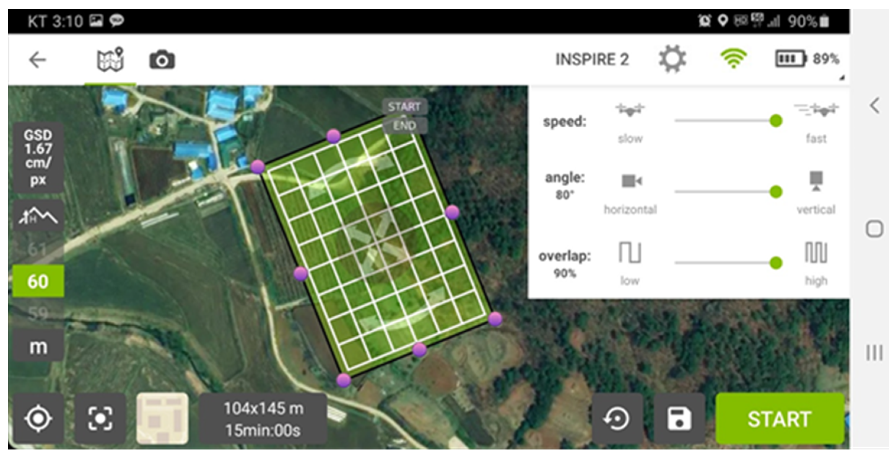
The initial design was created by architectural designers based on the digital elevation map (DEM) from the National Geographic Information Institute (NGII) [24] which is officially managing DEMs for public use. As shown in Figure 1a, the draft of the site design was created (see red line). The DEM was created by aerial survey in 2005, and it has not been updated since, therefore, design review is essential prior to be constructed. In the initial stage of housing design, architects concede the DEM was conducted as a primary source unless on-site mapping (because the DEM from NGII is the only available source). The difference between the actual terrain and the DEM is typically corrected during construction. As we mentioned previously, there are several ways to verify the design. This study employed a UAV to create topographic digital terrain model. A quadcopter UAV, DJI’s Inspire 2 was used to acquire aerial pictures of the site [25] that attached with a gimbal and camera, Zenmuse X4S [26], and Pix4DmapperUAV based photogrammetry was used [27]. Ground Sample Distance (GSD) was 1.77 cm/px (flight height was 60 m).
Ten ground control points (GCPs) were installed to increase the accuracy of the point cloud. The installation of the GCPs was carried out according to a guideline [28] and were easily accessible to personnel and located evenly at the target site as shown in Figure 1b. The latitude and longitude coordinates of each ground reference point were measured using the real-time kinematic-Global Positioning System (RTK-GPS) and the altitude was directly measured since even RTK GPS has low reliability on the altitude estimation. Leica Geosystem’s GS18T was used for surveying. According to the specification, measurement accuracy during network RTK is Hz 8 mm + 0.5 ppm/V 15 mm + 0.5 ppm. The coordinate of the GCPs is shown in Table 1, and the coordinate was based on the Bessel ellipsoid and Transverse Mercator (TM) Korean Central Belt projections, and altitude was the result of direct level measurements using RTS. Figure 2 shows the flowchart of GCP marking. First, every UAV flight must obey the Act on Promotion of Utilization of Drones and Creation of Infrastructure Therefor [29]. In this regard, a UAV pilot must check the no-fly zone (e.g., military-related areas, near the airport, etc.) before take-off to make sure that the flight path stays out of the restricted areas. Second, GCPs (ground control points) were acquired via RTK (real-time kinematic) GPS as well as leveling using a total station. The location of the GCPs was shown in Table 1. Lastly, the GCPs were properly marked on the surface [28].
To acquire the point cloud, aerial photography using UAVs was carefully planned during the planning phase. An aerial photography plan was established to prevent the collisions of UAVs, include all sites, and ensure the quality of data by considering the presence of obstacles, flight altitude, long corridor, flight time, optimal route, and light during UAV take-off and landing. Figure 3 shows the results of the flight plan considering the presence of obstacles, flight altitude, long corridor, flight time, etc. It was able to cover the entire site with one flight and flew at an altitude of 60 m above the mountainous area. At the time of aerial photography, the weather was clear, and it flew in relatively stable flight conditions with a wind speed of 2.6 m/s and a temperature of 24 °C. The flight time zone used the minimum shadow time across the site around 3 p.m., and the overlap of the picture was set at 90% longitudinal and 90% lateral. The original earthwork design was established based on the DEM from the NGII. Considering the inaccuracy of the DEM, verification of the original ground was conducted using UAV-based point cloud as well as Autodesk Civil 3D. The accuracy of the UAV-based point cloud map was not analyzed since acquiring ground-truth data was not on our scope of the study, however, this study strictly followed a standard UAV flight procedure as mentioned earlier (e.g., number of GCPs, location of GCPs, flight settings, etc.), the accuracy of the map that created from this study is up to 0.01 m in x and y-direction, and 0.04 m in z-direction [30].
3.3. Integration of Earthwork Design Review and Planning
Once the design review is completed, design revision was carried out by an earthwork engineer, the result of the design review (i.e., changes in design) may significantly result in the construction equipment operation. For example, if the elevation of the DEM is lower than the actual level, the earthwork pad (i.e., finishing ground) should be changed. This study adopted a task planning strategy developed by [1] so that the finishing ground model can further be incorporated. A complete coverage path planning (CCPP) algorithm was used to create a path of the excavator and its work sequence. The complete coverage path planning is the sequence of maneuvers consisting of a predefined number of line segments and arcs that will be employed to generate the total coverage path. For example, a CCPP can be applied when a domestic cleaning robot sweeps the entire floor, the lawnmower cuts the grass on a yard, a tractor harvest crops, or a drone flies over terrain for photogrammetry, and also for excavator digs that and shape sites. Therefore, in this study, CCPP was adopted to represent the task planning strategy to plan an earthwork.
4. Results
4.1. Earthwork Design Review
The main purpose of the design review is to check whether or not the initial design applies to the site. Two digital terrain models were compared, and the difference between the DEM and UAV-based 3D point cloud map is approximately 70 cm. Due to the elevation discrepancy, the earthwork volume of the initial design was imbalanced; the cut volume was 816.7 cubic meters and the fill volume was 102.25 cubic meters. After raising the building pad from 75.0 m to 75.7 m, the cut and fill volumes were changed to 481.21 cubic meters and 349.54 cubic meters, respectively (see Figure 4a,b). Eventually, by reviewing and revising the building pad, the earthwork balance between the cut and fill was significantly reduced by 82%. Figure 4c shows the as-built model of the design. Figure 5 shows the drainage flow of the site. Because the northern part of the site has a higher ground level, the main drainage pipe was buried along the access road (see Figure 1b), with the installed drainage duct wrapped around the bottom of the slope.
4.2. Integrating Earthwork Design and Planning
To establish an operational plan for the earthwork equipment based on the complementary design, the most commonly-used cell-based ground segmentation was carried out. To this end, the earthwork design function of Autodesk Civil 3D was used to generate a square cell of 3 m in size and calculate the volume between the original ground and the finishing ground, respectively, to fill and cut volume. Based on these calculations, this study determined that it would be correct to proceed with the earthwork in two stages. The first was to transport the soil on the north side to the finishing ground, and the second was to transport the soil piled up in the center to the junction area and the south side. Figure 6a shows the result of the earthwork construction plan of the Civil 3D, and it only shows the cut and fills the volume of each cell.
Considering the design of the earthwork plan in a way that minimizes the overall earthwork balance and earthwork haulage distance, the yellow shaded cut-off zone (phase 1) shall be moved to the left and upper left, and the blue shaded cut-off zone (phase 2) shall be moved to the lower left as shown in Figure 5. Based on the general principle of the earthwork planning strategy, and in order to develop a more specific earthwork plan, this study generated cells spaced 3 m apart to further refine the area as shown in Figure 6b. The earthwork construction plan was set to move soil from A-zone to B-zone, and from C-zone to D-zone, respectively. The cut volume of the A-zone is 59.63 cubic meters, and upper part of the C-zone is 96.37 cubic meters, and the lower part of the C-zone is 279.97 cubic meters. The fill volume of the B-zone is 155.59 cubic meters, and D-zone is 166.754 cubic meters. The total cut and fill volume of the earthwork site are shown in Table 2, and Figure 7.
After the BIM software generates the cut and fill grid map and division of phases, the basic work environment information (e.g., entrance, the shape of each phase, grid size, etc.) must be imported to the CCPP software for the operation level of earthwork plan (i.e., the equipment work sequence) The earthwork construction plan from Civil 3D can be exported as csv files and the data can be connected to the CCPP algorithm. As shown in Figure 8, the geometric shape of each phase was imported from BIM. Considering the amount of earthwork volume and the scheduled construction period, it was agreed that the earthworks only had to be completed within 14 days after discussing with an owner. In this study, a 5.9-ton excavator with a 0.18 cubic meter bucket was employed. Although the excavator is relatively small, the size of the site is small as well, so the excavator was able to work within two weeks with the sole operation of the excavator, and the actual construction period was 11 days. A dozer blade (2 by 0.338 m) was attached in front of the excavator so that excavated soil could be moved by using the blade.
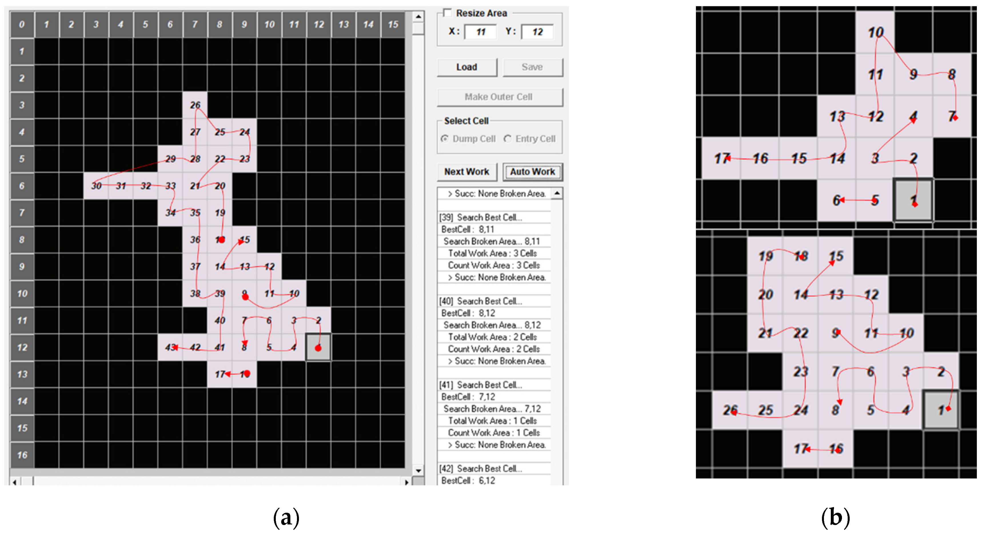
In order to perform the excavation and fill operations, it is necessary to generate a sequence of operations of excavators based on a 3 m cell that takes into account the separation of the work areas of the first and second stages and the working radius of the excavator. In this regard, we used the developed CCPP software [1] and generated a coverage path plan for zone C in phase 2. The CCPP software is able to produce near-optimal earthwork planning (i.e., travel sequences for an excavator) and is believed to be helpful when a single excavator is employed in a relatively small site. The coverage path plan was divided into two sections when the C zone was viewed as one and worked in two. The reason why zone C is divided into upper and lower sections is that the soil at the top may travel through zone A to the left of stage 1. In all cases, the starting point was to start at the lower right corner, where the amount of cutting was relatively high. When combined, as shown in Figure 8, we create a path to work by gradually moving the volume from right to left. When the coverage path plan was created by dividing the C zone into two zones, zone 1 and zone 2, a path was created to move soil to the left, similar to the previous case.
This pattern was similarly shown in coverage path planning in zone A. However, the plan was to start from the lower left corner, which is the boundary between cut and fill, due to the lack of slope and earthwork in A area A was planned. As shown in Figure 9, the cutting part on the right side of Cell 10 to Cell 19 produced the result of working on a continuous path from Cell 1 to Cell 9.
5. Discussions
This study set out to gain further understanding of UAV-based 3D map usage in the construction industry by seamlessly integrating the earthwork design review and earthwork planning. This study incorporated the real data from a housing construction project in Korea to prove the feasibility of the integration process of UAV-based 3D map acquisition to earthwork planning. In terms of the earthwork design review, altitude errors occurred at most points. It is suspected that it is probably caused by weathering. In fact, the site is located at the edge of the mountain and has a high slope in the north, so it is believed that many soils have been swept away through the slope due to rain or snow melting. Therefore, the earthwork calculated from the actual design was over-estimated, in turn, the fill volume was under-estimated. The National Geographic Information Institute (NGII) of Korea provides DEM for public use, and the DEM must be regularly updated by local governments. The update frequency, however, depends on the local government’s budget situation, so, in some rural areas where a sufficient budget is not available to have outdated DEM, it could be up to 10 years. To mitigate such a discrepancy, UAV-based mapping should be conducted prior to the initial design. Although it is always common for field engineers to make immediate and on-the-fly decisions on earthwork equipment plans and specific work sequences, there have never been any studies reviewed from the design stage to the work sequences of the earthwork equipment. Based on the actual construction site case, it is confirmed that the UAV, BIM, and earthwork equipment task planning process could be integrated into a single pipeline, and it could contribute to reducing construction costs and duration in that it could solve problems such as redesign and reconstruction due to design errors. Additionally, these findings might help us to develop an automated earthwork planning system.
6. Conclusions
The goal of this work is to improve the existing earthwork review and planning procedures by simultaneously utilizing UAV-based point clouds, BIM, and earthwork equipment task strategy (CCPP). First, we obtain a reliable terrain model using UAV-based point cloud mapping, which makes it difficult to identify design errors right before the construction survey and modify the earthwork design by converging and reviewing new terrain models and housing project design data using BIM software. To this extent, UAV utilization in earthworks was conducted based on the second-most changed design drawings in this study, and the results were used to establish the operation plan of earthworks equipment. It has been true that the prior research so far has only been based on earthwork analysis, so it is not very useful for earthworks controllers or equipment drivers who actually work in earthworks. Considering that almost all the earthwork is covered by earthwork equipment, the UAV and BIM integration process proposed in this study is expected to be highly practical in methods and procedures that extend from UAVs to construction equipment operations.
Despite these promising results, questions remain. Further research is needed to gain a better understanding of the automated earthwork systems. First, practical implications are hard to achieve in that it is highly likely that the construction of the work plan and sequence will not be carried out as originally planned, as the ground is excavated and frequently changed by the judgment of the excavator operator. In particular, considering that many construction equipment manufacturers have recently made efforts to develop autonomous driving equipment incorporating technologies such as LiDAR and object recognition, process integration studies such as this study must precede. If SLAM (simultaneous localization and mapping) technologies using LiDAR are activated in the future, we believe that technologies that can generate work plans closer to real-time will be developed, and research and development in the related fields are necessary. Despite many implications, the most important limitation lies in the fact that this study has been conducted on a relatively small construction site so that it adds further caution regarding the generalizability of these findings. Notwithstanding these limitations, the study will be of interest to earthwork field engineers and site designers, and it illustrates how traditional earth-work design can be improved using state-of-the-art technologies such as UAV, BIM, and advanced algorithms.
Author Contributions
Conceptualization, J.K. and S.L.; methodology, J.K., S.L., J.S. and H.S.C.; validation, J.K., S.L. and D.-E.L.; formal analysis, J.K.; investigation, J.S.; writing—original draft preparation, J.K. and S.L.; writing—review and editing, J.K. All authors have read and agreed to the published version of the manuscript.
Funding
This work was supported by the National Research Foundation of Korea (NRF) grant funded by the Korea government (MEST) (No. NRF-2019R1A2C2006577), and ERC (No. NRF-2018R1A5A1025137).
Institutional Review Board Statement
Not applicable.
Informed Consent Statement
Not applicable.
Data Availability Statement
Not relevant.
Acknowledgments
This work was supported by the National Research Foundation of Korea (NRF) grant funded by the Korea government (MSIT) (No. NRF-2018R1A5A1025137).
Conflicts of Interest
The authors declare no conflict of interest.
References
- Kim, J.; Lee, D.; Seo, J. Task Planning Strategy and Path Similarity Analysis for an Autonomous Excavator. Autom. Constr. 2020, 112, 103108. [Google Scholar] [CrossRef]
- FHWA Maintenance of Drainage Features for Safety. Available online: https://safety.fhwa.dot.gov/local_rural/training/fhwasa09024/ (accessed on 18 January 2021).
- Vaze, J.; Teng, J.; Spencer, G. Impact of DEM Accuracy and Resolution on Topographic Indices. Environ. Model. Softw. 2010, 25, 1086–1098. [Google Scholar] [CrossRef]
- Siebert, S.; Teizer, J. Mobile 3D Mapping for Surveying Earthwork Projects Using an Unmanned Aerial Vehicle (UAV) System. Autom. Constr. 2014, 41, 1–14. [Google Scholar] [CrossRef]
- Kwon, S.; Park, J.W.; Moon, D.; Jung, S.; Park, H. Smart Merging Method for Hybrid Point Cloud Data Using UAV and LIDAR in Earthwork Construction. Procedia Eng. 2017, 196, 21–28. [Google Scholar] [CrossRef]
- Kim, S.-K.; Seo, J.; Russell, J.S. Intelligent Navigation Strategies for an Automated Earthwork System. Autom. Constr. 2012, 21, 132–147. [Google Scholar] [CrossRef]
- Goessens, S.; Mueller, C.; Latteur, P. Feasibility Study for Drone-Based Masonry Construction of Real-Scale Structures. Autom. Constr. 2018, 94, 458–480. [Google Scholar] [CrossRef]
- Raza, H.; Tanoli, W.; Lee, S.; Seo, J. Flexible Earthwork BIM Module Framework for Road Project. In Proceedings of the 34th International Symposium on Automation and Robotics in Construction (ISARC), Taipei, Taiwan, 28 June–1 July 2017; pp. 410–415. [Google Scholar] [CrossRef] [Green Version]
- Akgul, M.; Yurtseven, H.; Gulci, S.; Akay, A.E. Evaluation of UAV- and GNSS-Based DEMs for Earthwork Volume. Arab. J. Sci. Eng. 2018, 43, 1893–1909. [Google Scholar] [CrossRef]
- Li, J.; Hou, L.; Wang, X.; Wang, J.; Guo, J.; Zhang, S.; Jiao, Y. A Project-Based Quantification of BIM Benefits. Int. J. Adv. Robot. Syst. 2014, 11, 123. [Google Scholar] [CrossRef]
- Raeva, P.L.; Filipova, S.L.; Filipov, D.G. Volume computation of a stockpile—A study case comparing gps and uav measurements in an open pit quarry. Int. Arch. Photogramm. Remote Sens. Spat. Inf. Sci. 2016, XLI-B1, 999–1004. [Google Scholar] [CrossRef] [Green Version]
- Ameri, B.; Meger, D.; Power, K.; Gao, Y. Uas Applications: Disaster & Emergency Management. In Proceedings of the ASPRS 2009 Annual Conference, Baltimore, MD, USA, 9–13 March 2009; pp. 45–55. [Google Scholar]
- Saari, H.; Pellikka, I.; Pesonen, L.; Tuominen, S.; Heikkilä, J.; Holmlund, C.; Mäkynen, J.; Ojala, K.; Antila, T. Unmanned Aerial Vehicle (UAV) Operated Spectral Camera System for Forest and Agriculture Applications. Remote Sens. Agric. Ecosyst. Hydrol. XIII 2011, 8174, 81740H. [Google Scholar] [CrossRef]
- Duque, L.; Seo, J.; Wacker, J. Bridge Deterioration Quantification Protocol Using UAV. J. Bridge Eng. 2018, 23, 1–12. [Google Scholar] [CrossRef]
- Chen, S.; Laefer, D.F.; Mangina, E.; Zolanvari, S.M.I.; Byrne, J. UAV Bridge Inspection through Evaluated 3D Reconstructions. J. Bridge Eng. 2019, 24, 1–15. [Google Scholar] [CrossRef] [Green Version]
- Tan, Y.; Li, Y. UAV Photogrammetry-Based 3D Road Distress Detection. ISPRS Int. J. Geo-Inf. 2019, 8, 409. [Google Scholar] [CrossRef] [Green Version]
- D’Oleire-Oltmanns, S.; Marzolff, I.; Peter, K.D.; Ries, J.B. Unmanned Aerial Vehicle (UAV) for Monitoring Soil Erosion in Morocco. Remote Sens. 2012, 4, 3390–3416. [Google Scholar] [CrossRef] [Green Version]
- Xie, F.; Lin, Z.; Gui, D.; Lin, H. Study on Construction of 3D Building Based on Uav Images. ISPRS-Int. Arch. Photogramm. Remote Sens. Spat. Inf. Sci. 2012, XXXIX-B1, 469–473. [Google Scholar] [CrossRef] [Green Version]
- Cheng, J.C.P.; Deng, Y. An Integrated BIM-GIS Framework for Utility Information Management and Analyses. Comput. Civ. Eng. 2015, 2015, 667–674. [Google Scholar] [CrossRef]
- Julge, K.; Ellmann, A.; Köök, R. Unmanned Aerial Vehicle Surveying for Monitoring Road Construction Earthworks. Balt. J. Road Bridge Eng. 2019, 14, 1–17. [Google Scholar] [CrossRef]
- Hudzietz, B.P.; Saripalli, S. An Experimental Evaluation of 3D Terrain Mapping With an Autonomous Helicopter. ISPRS-Int. Arch. Photogramm. Remote Sens. Spat. Inf. Sci. 2012, XXXVIII-1/C22, 137–142. [Google Scholar] [CrossRef] [Green Version]
- Piras, M.; Taddia, G.; Forno, M.G.; Gattiglio, M.; Aicardi, I.; Dabove, P.; Russo, S.L.; Lingua, A. Detailed Geological Mapping in Mountain Areas Using an Unmanned Aerial Vehicle: Application to the Rodoretto Valley, NW Italian Alps. Geomat. Nat. Hazards Risk 2017, 8, 137–149. [Google Scholar] [CrossRef]
- Pi, Y.; Nath, N.D.; Behzadan, A.H. Convolutional Neural Networks for Object Detection in Aerial Imagery for Disaster Response and Recovery. Adv. Eng. Inform. 2020, 43, 101009. [Google Scholar] [CrossRef]
- NGII Integrated Map. Available online: http://map.ngii.go.kr/ms/map/NlipMap.do (accessed on 11 March 2021).
- DJI. DJI’s Inspire 2. Available online: https://www.dji.com/inspire-2 (accessed on 11 March 2021).
- DJI. Zenmuse X4S. Available online: https://www.dji.com/zenmuse-x4s (accessed on 11 March 2021).
- Pix4D. Pix4Dmapper. Available online: https://www.pix4d.com/product/pix4dmapper-photogrammetry-software (accessed on 11 March 2021).
- Pix4D Ground Control Points: Why Are They Important? Available online: /blog/why-ground-control-points-important (accessed on 11 March 2021).
- Korea Legislation Research Institute Act on Promotion of Utilization of Drones and Creation of Infrastructure Therefor. Available online: https://elaw.klri.re.kr/kor_service/lawView.do?hseq=53139&lang=ENG (accessed on 11 March 2021).
- Tomaštík, J.; Mokroš, M.; Surový, P.; Grznárová, A.; Merganič, J. UAV RTK/PPK Method—An Optimal Solution for Mapping Inaccessible Forested Areas? Remote Sens. 2019, 11, 721. [Google Scholar] [CrossRef] [Green Version]
Figure 1.
(a) The initial DEM of the building site (red dotted line is the boundary of the site); (b) location of the ground control points.
Figure 1.
(a) The initial DEM of the building site (red dotted line is the boundary of the site); (b) location of the ground control points.

Figure 2.
Flowchart of the ground control point (GCP) marking.

Figure 3.
The UAV’s flight path setting; a screenshot of the Pix4D app.

Figure 4.
The results of design review: (a) initial design; (b) revised design; (c) after construction (yellow: existing terrain, grey: building pad).
Figure 4.
The results of design review: (a) initial design; (b) revised design; (c) after construction (yellow: existing terrain, grey: building pad).

Figure 5.
Drainage flow of the site.

Figure 6.
Earthwork construction map: (a) fill and cut volume calculation; (b) zone division based on more detailed (3 m grid map based zone).
Figure 6.
Earthwork construction map: (a) fill and cut volume calculation; (b) zone division based on more detailed (3 m grid map based zone).

Figure 7.
Division of the section of the earthwork site.

Figure 8.
Earthwork planning results of C-zone: (a) fill and cut volume calculation; (b) zone-division based on more detailed (3 m grid map based zone).
Figure 8.
Earthwork planning results of C-zone: (a) fill and cut volume calculation; (b) zone-division based on more detailed (3 m grid map based zone).

Figure 9.
Path planning result of A zone.


Table 1.
Coordinates of the ground control points.
| GCPs | Northing (m) | Easting (m) | Elevation (m) |
|---|---|---|---|
| 1 | 354,794.355 | 211,658.751 | 72.34 |
| 2 | 354,788.336 | 211,653.043 | 71.959 |
| 3 | 354,736.735 | 211,687.548 | 75.175 |
| 4 | 354,723.373 | 211,703.816 | 74.206 |
| 5 | 354,768.343 | 211,679.642 | 74.979 |
| 6 | 354,756.908 | 211,664.313 | 73.835 |
| 7 | 354,747.569 | 211,677.045 | 75.791 |
| 8 | 354,757.486 | 211,692.782 | 78.496 |
| 9 | 354,740.068 | 211,698.525 | 75.993 |
| 10 | 354,751.823 | 211,686.751 | 75.958 |
Table 2.
Cut and fill volumes for each area.
| Classification | Cut (m3) | Fill (m3) | Net (m3) |
|---|---|---|---|
| Phase 1 | 58.77 | 138.096 | 79.326 |
| Phase 2 | 205.74 | 139.491 | 66.249 |
| Access road | 0.86 | 17.901 | 17.041 |
| Slope area | 165.6 | 25.263 | 140.337 |
| Total | 430.97 | 320.751 | 110.219 |
Publisher’s Note: MDPI stays neutral with regard to jurisdictional claims in published maps and institutional affiliations. |
© 2021 by the author. Licensee MDPI, Basel, Switzerland. This article is an open access article distributed under the terms and conditions of the Creative Commons Attribution (CC BY) license (https://creativecommons.org/licenses/by/4.0/).
Share and Cite
MDPI and ACS Style
Kim, J.; Lee, S.; Seo, J.; Lee, D.-E.; Choi, H.S. The Integration of Earthwork Design Review and Planning Using UAV-Based Point Cloud and BIM. Appl. Sci. 2021, 11, 3435. https://0-doi-org.brum.beds.ac.uk/10.3390/app11083435
AMA Style
Kim J, Lee S, Seo J, Lee D-E, Choi HS. The Integration of Earthwork Design Review and Planning Using UAV-Based Point Cloud and BIM. Applied Sciences. 2021; 11(8):3435. https://0-doi-org.brum.beds.ac.uk/10.3390/app11083435
Chicago/Turabian StyleKim, Jeonghwan, Soomin Lee, Jongwon Seo, Dong-Eun Lee, and Hee Seon Choi. 2021. "The Integration of Earthwork Design Review and Planning Using UAV-Based Point Cloud and BIM" Applied Sciences 11, no. 8: 3435. https://0-doi-org.brum.beds.ac.uk/10.3390/app11083435
Note that from the first issue of 2016, this journal uses article numbers instead of page numbers. See further details here.