
Automatic Electromechanical Perturbator for Postural Control Analysis Based on Model Predictive Control


Abstract
:1. Introduction
2. Materials and Methods
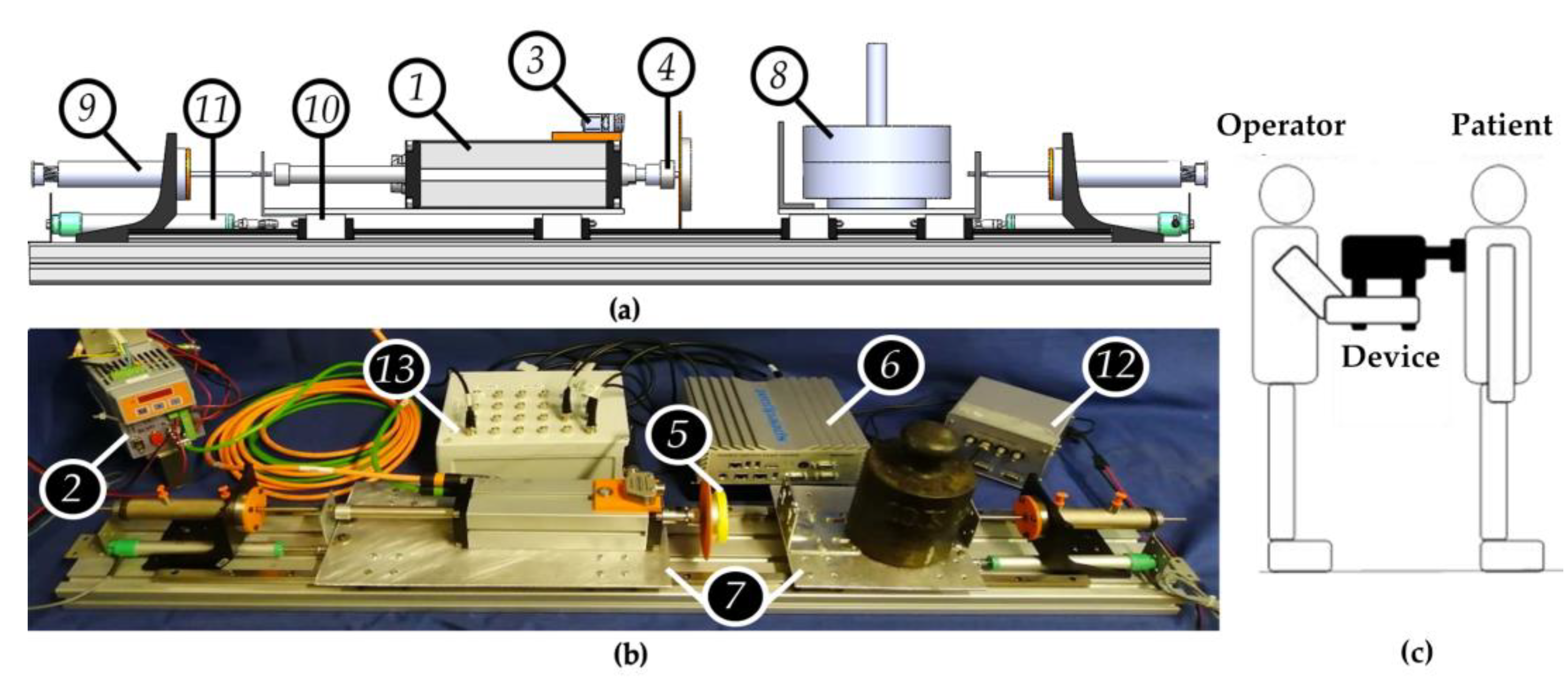
2.1. Test-Bench and Automatic Perturbator Architecture
2.2. Model and Control System Design
- Idle: the actuator’s rod remains still in the retracted position;
- Approach: the piston nears the target body following a constant speed reference signal. It is triggered by the occurrence of the start command delivered by the operator;
- Strike: the actuator meets the target body and force reference control is issued. It is triggered by a 2.5 N threshold on the load cell signal;
- Retraction: the actuator’s rod returns to the retracted position with constant speed after having completed or failed to enact the strike phase.
2.3. Simulations and Experimentation
- R1: rectangular reference signal of 50 N with 75 ms duration (reference FI = 3.75 Ns);
- R2: rectangular reference signal of 50 N with 250 ms duration (reference FI = 12.5 Ns).
3. Results
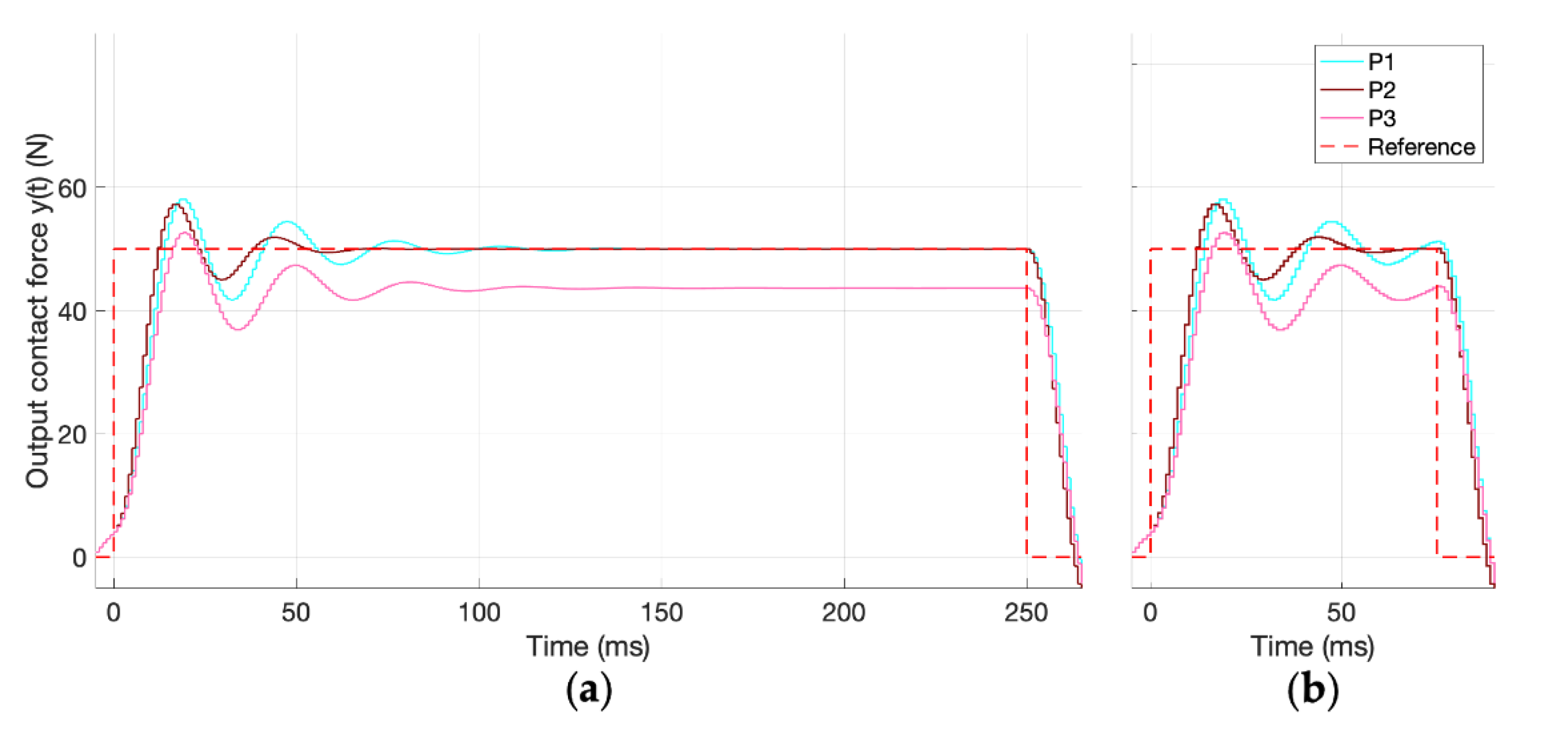
3.1. MIL Results
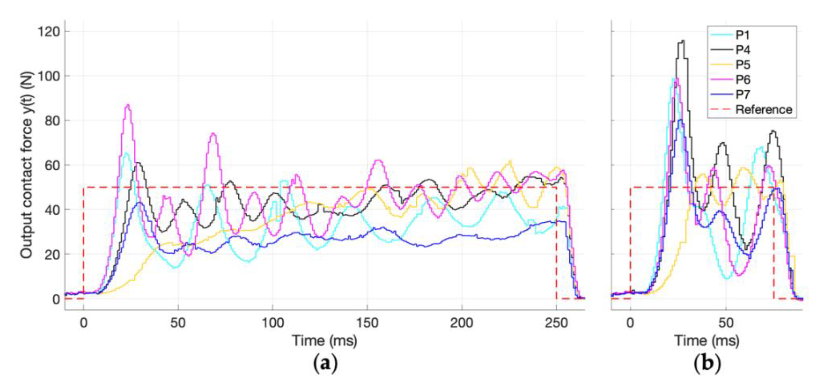
3.2. HIL Results
4. Discussion
5. Conclusions
6. Patents
Author Contributions
Funding
Institutional Review Board Statement
Informed Consent Statement
Data Availability Statement
Conflicts of Interest
References
- Chen, B.; Lee, Y.J.; Aruin, A.S. Role of point of application of perturbation in control of vertical posture. Exp. Brain Res. 2017, 235, 3449–3457. [Google Scholar] [CrossRef] [PubMed]
- Martinelli, A.R.; Coelho, D.B.; Magalhães, F.H.; Kohn, A.F.; Teixeira, L.A. Light touch modulates balance recovery following perturbation: From fast response to stance restabilization. Exp. Brain Res. 2015, 233, 1399–1408. [Google Scholar] [CrossRef] [PubMed]
- Shahvarpour, A.; Shirazi-Adl, A.; Mecheri, H.; Larivière, C. Trunk response to sudden forward perturbations—Effects of preload and sudden load magnitudes, posture and abdominal antagonistic activation. J. Electromyogr. Kinesiol. 2014, 24, 394–403. [Google Scholar] [CrossRef] [PubMed]
- Kim, J.; Kim, C.; Lee, J.; Kwon, Y.; Eom, G.; Tak, G.; Hong, J. Human postural control against external force perturbation applied to the high-back. Int. J. Precis. Eng. Manuf. 2009, 10, 147–151. [Google Scholar] [CrossRef]
- Teixeira, L.A.; Azzi, N.; de Oliveira, J.Á.; Ribeiro de Souza, C.; Rezende, L.; Coelho, D. Automatic postural responses are scaled from the association between online feedback and feedforward control. Eur. J. Neurosci. 2019, 51, 2023–2032. [Google Scholar] [CrossRef]
- Pasman, E.P.; McKeown, M.J.; Cleworth, T.W.; Bloem, B.R.; Inglis, J.T.; Carpenter, M.G. A Novel MRI Compatible Balance Simulator to Detect Postural Instability in Parkinson’s Disease. Front. Neurol. 2019, 10, 922–930. [Google Scholar] [CrossRef] [PubMed]
- van der Kooij, H.; Peterka, R.J. Non-linear stimulus-response behavior of the human stance control system is predicted by optimization of a system with sensory and motor noise. J. Comput. Neurosci. 2011, 30, 759–778. [Google Scholar] [CrossRef] [PubMed] [Green Version]
- van der Kooij, H.; de Vlugt, E. Postural responses evoked by platform perturbations are dominated by continuous feedback. J. Neurophysiol. 2007, 98, 730–743. [Google Scholar] [CrossRef] [Green Version]
- Potocanac, Z.; Golijat, R.; Babic, J. A robotic system for delivering novel real-time, movement dependent perturbations. Gait Posture 2017, 58, 386–389. [Google Scholar] [CrossRef]
- Potocanac, Z.; de Bruin, J.; van der Veen, S.; Verschueren, S.; van Dieën, J.; Duysens, J.; Pijnappels, M. Fast online corrections of tripping responses. Exp. Brain Res. 2014, 232, 3579–3590. [Google Scholar] [CrossRef] [Green Version]
- Bieryla, K.A.; Madigan, M.L.; Nussbaum, M.A. Practicing recovery from a simulated trip improves recovery kinematics after an actual trip. Gait Posture 2007, 26, 208–213. [Google Scholar] [CrossRef]
- Ruhe, A.; Fejer, R.; Walker, B. The test-retest reliability of centre of pressure measures in bipedal static task conditions--a systematic review of the literature. Gait Posture 2010, 32, 436–445. [Google Scholar] [CrossRef] [Green Version]
- Dvir, Z.; Paterna, M.; Quargnenti, M.; De Benedictis, C.; Maffiodo, D.; Franco, W.; Ferraresi, C.; Manca, A.; Deriu, F.; Roatta, S. Linearity and repeatability of postural responses in relation to peak force and impulse of manually delivered perturbations: A preliminary study. Eur. J. Appl. Physiol. 2020, 120, 1319–1330. [Google Scholar] [CrossRef]
- Forghani, A.; Preuss, R.; Milner, T.E. Short-latency muscle response patterns to multi-directional, unpredictable perturbations to balance applied to the arm are context dependent. Neuroscience 2017, 352, 170–179. [Google Scholar] [CrossRef]
- Robbins, S.M.; Caplan, R.M.; Aponte, D.I.; St-Onge, N. Test–retest reliability of a balance testing protocol with external perturbations in young healthy adults. Gait Posture 2017, 58, 433–439. [Google Scholar] [CrossRef]
- Boonstra, T.A.; Schouten, A.C.; van der Kooij, H. Identification of the contribution of the ankle and hip joints to multi-segmental balance control. J. Neuroeng. Rehabil. 2013, 10, 23. [Google Scholar] [CrossRef] [PubMed] [Green Version]
- Hubble, R.P.; Naughton, G.A.; Silburn, P.A.; Cole, M.H. Wearable sensor use for assessing standing balance and walking stability in people with Parkinson’s disease: A systematic review. PLoS ONE 2015, 10, e0123705. [Google Scholar] [CrossRef] [Green Version]
- Rajachandrakumar, R.; Mann, J.; Schinkel-Ivy, A.; Mansfield, A. Exploring the relationship between stability and variability of the centre of mass and centre of pressure. Gait Posture 2018, 63, 254–259. [Google Scholar] [CrossRef]
- Le Mouel, C.; Tisserand, R.; Robert, T.; Brette, R. Postural adjustments in anticipation of predictable perturbations allow elderly fallers to achieve a balance recovery performance equivalent to elderly non-fallers. Gait Posture 2019, 71, 131–137. [Google Scholar] [CrossRef] [PubMed] [Green Version]
- Lee, Y.J.; Chen, B.; Aruin, A.S. Older adults utilize less efficient postural control when performing pushing task. J. Electromyogr. Kinesiol. 2015, 25, 966–972. [Google Scholar] [CrossRef] [PubMed] [Green Version]
- Piscitelli, D.; Falaki, A.; Solnik, S.; Latash, M.L. Anticipatory postural adjustment and anticipatory synergy adjustment: Preparing to a postural perturbation with predictable and unpredictable direction. Exp. Brain Res. 2017, 235, 713–730. [Google Scholar] [CrossRef]
- Xie, L.; Wang, J. Anticipatory and compensatory postural adjustments in response to loading perturbation of unknown magnitude. Exp. Brain Res. 2019, 237, 173–180. [Google Scholar] [CrossRef] [PubMed]
- Cherubini, A.; Passama, R.; Crosnier, A.; Lasnier, A.; Fraisse, P. Collaborative manufacturing with physical human-robot interaction. Robot. Comput. Integr. Manuf. 2016, 40, 1–13. [Google Scholar] [CrossRef] [Green Version]
- Gosselin, C.; Laliberte, T.; Mayer-St-Onge, B.; Foucault, S.; Lecours, A.; Duchaine, V.; Paradis, N.; Gao, D.; Menassa, R. A friendly beast of burden: A human-assistive robot for handling large payloads. IEEE Robot. Autom. Mag. 2013, 20, 139–147. [Google Scholar] [CrossRef]
- Riener, R.; Lünenburger, L.; Colombo, G. Human-centered robotics applied to gait training and assessment. J. Rehabil. Res. Dev. 2006, 43, 679–694. [Google Scholar] [CrossRef] [PubMed]
- Zhang, J.; Cheah, C.C.; Collins, S.H. Stable human-robot interaction control for upper-limb rehabilitation robotics. In Proceedings of the 2013 IEEE International Conference on Robotics and Automation, Karlsruhe, Germany, 6–10 May 2013; pp. 2201–2206. [Google Scholar]
- Heidingsfeld, M.; Feuer, R.; Karlovic, K.; Maier, T.; Sawodny, O. A force-controlled human-assistive robot for laparoscopic surgery. In Proceedings of the 2014 IEEE International Conference on Systems, Man, and Cybernetics (SMC), San Diego, CA, USA, 5–8 October 2014; Volume 43, pp. 3435–3439. [Google Scholar]
- Maffiodo, D.; Franco, W.; De Benedictis, C.; Paterna, M.; Muscolo, G.G.; Roatta, S.; Ferraresi, C.; Dvir, Z. Pneumo-tronic Perturbator for the Study of Human Postural Responses. Adv. Intell. Syst. Comput. 2020, 980, 374–383. [Google Scholar]
- Ferraresi, C.; De Benedictis, C.; Muscolo, G.G.; Pica, O.W.; Genovese, M.; Maffiodo, D.; Franco, W.; Paterna, M.; Roatta, S.; Dvir, Z. Development of an automatic perturbator for dynamic posturographic analysis. New Trends Med. Serv. Robots 2021, 93, 273–282. [Google Scholar]
- Ferraresi, C.; Maffiodo, D.; Franco, W.; Muscolo, G.G.; De Benedictis, C.; Paterna, M.; Pica, O.W.; Genovese, M.; Pacheco Quiñones, D.; Roatta, S.; et al. Hardware-In-the-Loop Equipment for the Development of an Automatic Perturbator for Clinical Evaluation of Human Balance Control. Appl. Sci. 2020, 10, 8886. [Google Scholar] [CrossRef]
- Diener, H.C.; Horak, F.B.; Nashner, L.M. Influence of stimulus parameters on human postural responses. J. Neurophysiol. 1988, 59, 1888–1905. [Google Scholar] [CrossRef]
- Madani, M.; Moallem, M. Hybrid position/force control of a flexible parallel manipulator. J. Frankl. Inst. 2011, 348, 999–1012. [Google Scholar] [CrossRef]
- Barjuei, E.S. Hybrid position/force control of a spatial compliant mechanism. Int. J. Automot. Mech. Eng. 2017, 14, 4531–4541. [Google Scholar] [CrossRef]
- Guang, H.; Ji, L.; Shi, Y.; Misgeld, B.J.E. Dynamic Modeling and Interactive Performance of PARM: A Parallel Upper-Limb Rehabilitation Robot Using Impedance Control for Patients after Stroke. J. Healthc. Eng. 2018, 2018, 8647591. [Google Scholar] [CrossRef] [Green Version]
- Keemink, A.Q.L.; van der Kooij, H.; Stienen, A.H.A. Admittance control for physical human-robot interaction. Int. J. Robot. Res. 2018, 37, 1421–1444. [Google Scholar] [CrossRef] [Green Version]
- Lopes, A.M.; Almeida, F.G. Force–impedance control of a six-dof parallel manipulator. In Intelligent Engineering Systems and Computational Cybernetics; Machado, J.A.T., Pátkai, B., Rudas, I.J., Eds.; Springer: Dordrecht, The Netherlands, 2009; pp. 37–47. [Google Scholar]
- Anderson, R.J.; Spong, M.W. Hybrid impedance control of robotic manipulators. IEEE J. Robot. Autom. 1988, 4, 549–556. [Google Scholar] [CrossRef]
- Teramae, T.; Noda, T.; Morimoto, J. EMG-Based Model Predictive Control for Physical Human–Robot Interaction: Application for Assist-As-Needed Control. IEEE Robot. Autom. Lett. 2018, 3, 210–217. [Google Scholar] [CrossRef]
- dos Santos, W.M.; Siqueira, A.A.G. Optimal impedance via model predictive control for robot-aided rehabilitation. Control Eng. Pract. 2019, 93, 104177. [Google Scholar] [CrossRef]
- Mohd Faudzi, A.A.; Mustafa, N.D.; Osman, K. Force Control for a Pneumatic Cylinder Using Generalized Predictive Controller Approach. Math. Probl. Eng. 2014, 2014, 261829. [Google Scholar] [CrossRef]
- Richer, E.; Hurmuzlu, Y. A high performance pneumatic force actuator system: Part II—Nonlinear controller design. J. Dyn. Syst. Meas. Control 2000, 122, 426–434. [Google Scholar] [CrossRef]
- Slotine, J.J.; Sastry, S.S. Tracking control of non-linear systems using sliding surfaces, with application to robot manipulators. Int. J. Control 1983, 38, 465–492. [Google Scholar] [CrossRef] [Green Version]
- Pliego-Jiménez, J.; Arteaga-Pérez, M.A. Adaptive position/force control for robot manipulators in contact with a rigid surface with uncertain parameters. Eur. J. Control 2015, 22, 1–12. [Google Scholar] [CrossRef]
- Flores, P.; Lankarani, H.M. Contact Force Models for Multibody Dynamics, 1st ed.; Springer International Publishing: Cham, Switzerland, 2016. [Google Scholar]


| Number | Component |
|---|---|
| 1 | GD160Q motor (NiLAB GmbH, Klagenfurt am Wörthersee, Austria) |
| 2 | SLVD1N driver (Parker Hannifin Corp., Cleveland, USA) |
| 3 | Q4XTULAF400-Q8 optical sensor (Banner Engineering Corp., Plymouth, MN, USA) |
| 4 | UMM 50 kgf-ranged load cell (Dacell Co. Ltd., Cheongju, Korea) |
| 5 | Expanded polyethylene interface |
| 6 | Baseline Real-Time target machine (Speedgoat Inc., Natick, MA, USA) |
| 7 | Aluminum sliding plates |
| 8 | Target body weight |
| 9 | Custom made viscoelastic dampers |
| 10 | C-SHR28-1000-B4 linear guides (MISUMI, Europa GmbH, Frankfurt, Germany) |
| 11 | PZ-34-A-100 displacement transducers (GEFRAN, Provaglio d’Iseo, Italy) |
| 12 | DEWE-RACK-4 (Dewetron GmbH, Grambach, Austria) |
| 13 | Connection box for Real-Time target system |
| Symbols | Description |
|---|---|
| Actuator’s mass, displacement, and issued force | |
| Operator response’s damping and stiffness | |
| Target body’s mass, linear damping, stiffness, and displacement | |
| Rod’s mass, elongation at impact | |
| Interface’s damping, stiffness, contact force, and displacement |
| Symbol | ||
|---|---|---|
| Tracking error | Q | |
| Control input | ||
| Control input rate | ||
| Soft constraint violation | 1 |
| Profile | Q | Ref | TI (s) | TID (%) | FI (Ns) | FID (%) | |||
|---|---|---|---|---|---|---|---|---|---|
| P1 | 10 | 3.8 | 0 | 10 | R1 | 0.264 | −5.6 | 12.56 | −0.47 |
| (cyan) | R2 | 0.089 | −18.67 | 3.82 | −1.77 | ||||
| P2 | 10 | 6 | 0 | 10 | R1 | 0.263 | −5.2 | 12.57 | −0.56 |
| (brown) | R2 | 0.088 | −17.33 | 3.83 | −1.98 | ||||
| P3 | 10 | 3.8 | 1 | 10 | R1 | 0.269 | −5.6 | 11.00 | 11.96 |
| (pink) | R2 | 0.089 | −18.67 | 3.37 | 10.13 |
| Profile | Q | CF | Ref | TI (s) | TID (%) | FI (Ns) | FID (%) | FI CV * 100 | |||
|---|---|---|---|---|---|---|---|---|---|---|---|
| P1 | 10 | 3.8 | 0 | 10 | 1.14 | R1 | 0.256 | −2.4 | 8.35 | 33.17 | 7.14 |
| (cyan) | 1.45 | R2 | 0.077 | −2.7 | 3.08 | 17.92 | 2.66 | ||||
| P4 | 5 | 3.8 | 0 | 10 | 1 | R1 | 0.252 | −0.8 | 10.59 | 15.29 | 0.46 |
| (black) | 1.45 | R2 | 0.077 | −2.7 | 3.83 | −2.19 | 0.50 | ||||
| P5 | 5 | 1.5 | 0 | 10 | 1.23 | R1 | 0.254 | −1.6 | 9.36 | 25.10 | 0.34 |
| (orange) | 2.29 | R2 | 0.078 | −4 | 2.93 | 21.87 | 0.63 | ||||
| P6 | 5 | 6 | 0 | 10 | 1 | R1 | 0.255 | −2 | 11.01 | 11.93 | 0.88 |
| (violet) | 1 | R2 | 0.077 | −2.7 | 3.03 | 19.12 | 1.47 | ||||
| P7 | 5 | 3.8 | 1 | 10 | 1 | R1 | 0.252 | −0.8 | 6.69 | 46.47 | 0.55 |
| (blue) | 1.45 | R2 | 0.076 | −1.3 | 2.72 | 27.35 | 1.25 |
Publisher’s Note: MDPI stays neutral with regard to jurisdictional claims in published maps and institutional affiliations. |
© 2021 by the authors. Licensee MDPI, Basel, Switzerland. This article is an open access article distributed under the terms and conditions of the Creative Commons Attribution (CC BY) license (https://creativecommons.org/licenses/by/4.0/).
Share and Cite
Pacheco Quiñones, D.; Paterna, M.; De Benedictis, C. Automatic Electromechanical Perturbator for Postural Control Analysis Based on Model Predictive Control. Appl. Sci. 2021, 11, 4090. https://0-doi-org.brum.beds.ac.uk/10.3390/app11094090
Pacheco Quiñones D, Paterna M, De Benedictis C. Automatic Electromechanical Perturbator for Postural Control Analysis Based on Model Predictive Control. Applied Sciences. 2021; 11(9):4090. https://0-doi-org.brum.beds.ac.uk/10.3390/app11094090
Chicago/Turabian StylePacheco Quiñones, Daniel, Maria Paterna, and Carlo De Benedictis. 2021. "Automatic Electromechanical Perturbator for Postural Control Analysis Based on Model Predictive Control" Applied Sciences 11, no. 9: 4090. https://0-doi-org.brum.beds.ac.uk/10.3390/app11094090