Article

Development and Characterization of 3D Printed Multifunctional Bioscaffolds Based on PLA/PCL/HAp/BaTiO3 Composites

by
Emmanouela Mystiridou
1,2,
Anastasios C. Patsidis
1,2 and
Nikolaos Bouropoulos
1,2,*
1
Department of Materials Science, University of Patras, GR-26504 Patras, Greece
2
Foundation for Research and Technology Hellas, Institute of Chemical Engineering and High Temperature Chemical Processes, GR-26504 Patras, Greece
*
Author to whom correspondence should be addressed.
Submission received: 11 April 2021 / Revised: 29 April 2021 / Accepted: 5 May 2021 / Published: 7 May 2021
(This article belongs to the Special Issue Biomaterial Synthesis and Application)

Abstract

:
Bone substitute materials are placed in bone defects and play an important role in bone regeneration and fracture healing. The main objective of the present research is fabrication through the technique of 3D printing and the characterization of innovative composite bone scaffolds composed of polylactic acid (PLA), poly (ε-caprolactone) (PCL) while hydroxyapatite (HAp), and/or barium titanate (BaTiO3—BT) used as fillers. Composite filaments were prepared using a single screw melt extruder, and finally, 3D composite scaffolds were fabricated using the fused deposition modeling (FDM) technique. Scanning electron microscopy (SEM) images showed a satisfactory distribution of the fillers into the filaments and the printed objects. Furthermore, differential scanning calorimetry (DSC) measurements revealed that PLA/PCL filaments exhibit lower glass transition and melting point temperatures than the pure PLA filaments. Finally, piezoelectric and dielectric measurements of the 3D objects showed that composite PLA/PCL scaffolds containing HAp and BT exhibited piezoelectric coefficient (d33) values close to the human bone and high dielectric permittivity values.

Graphical Abstract

1. Introduction

Bone defects can be caused by accidents, tumor resection, genetic factors, or other pathological conditions. Although bone reconstruction is one of the most perfect healing procedures in the human body, in the case of large bone defects the intrinsic reconstruction by the organism is insufficient [1].
The treatment of bone defects using bone grafts is of particular importance in orthopedic, plastic, and maxillofacial surgery. The gold standard for treating large bone defects is autologous bone grafting in which bone is harvested from one site of the patient and transplanted to another site. However, this kind of implant has two main disadvantages: the limited amount of available bone and the surgical procedure required for bone harvesting, usually from the ilium or the calvarium. Allografts are grafts transplanted between genetically different individuals of the same species. Xenografts are bone transplants that are implanted to a person from a donor who belongs to a genetically different species. Allographs have the risks of immunoreactions and rejection while xenografts have the risk of disease transmission to the host [2,3].
The development of alloplastic materials that will exhibit osteoinductive properties and will be absorbed simultaneously with the formation of new bone led to the preparation of bone implants based on calcium phosphate (CP), such as CP cements or ceramics [4,5,6]. Furthermore, the range of other synthetic bone grafts includes metals, plastics, bioactive glasses, etc. [7].
In recent years there has been a strong interest in the manufacturing of smart implants for bone tissue engineering applications. The term “smart implants” refers to materials or constructs that indicate a reversible response to an external or internal stimulus such as pH, temperature, electric or magnetic field, mechanical forces, light, etc. This response enhances cell activity and induces tissue regeneration [8,9]. In the comprehensive review by Xia et al., new strategies of using magnetic materials for bone tissue engineering are described. For example, magnetic scaffolds containing superparamagnetic iron oxide nanoparticles (SPIONS) increase osteogenic differentiation, cell growth, and bone regeneration [10]. The effectiveness of magnetic field on bone tissue engineering applications depends on several factors, including the nature of magnetic nanoparticles, and the type of magnetic field (static or time-varying magnetic field) [11].
Another stimuli-responsive and non-invasive strategy used in bone tissue regeneration is based on light irradiation. The recent progress of light-responsive nanomaterials with applications in tissue engineering is reviewed by Wan et al. The light irradiation source is NIR light (700–1300 nm), which shows higher tissue penetration. NIR phototherapy for bone cancer treatment, is based on hyperthermia and can be used independently or in combination with NIR light-responsive nanoparticles. The most commonly used light-responsive nanomaterials include gold nanostructures, carbon-based nanomaterials (graphene, nanotubes), metal oxides, and sulfides such as magnetic nanoparticles, MOS2 nanosheets, etc. Incorporation of NIR light-responsive nanoparticles into 3D printed scaffolds combines the phototherapy of bone cancers with bone remodeling during therapy [12].
In addition to magnetic materials, soft materials in the form of temperature or pH responsive hydrogels are considered very important materials for bone repair. The main advantages of hydrogels are focused on their similarity with the extracellular matrix and their high biocompatibility since they are obtained from biogenic sources. Representative natural hydrogels include chitosan, alginate, gelatin, hyaluronic acid, etc. The drawback of these materials is their low mechanical properties and their low stability in aqueous solutions. However, chemically crosslinked hydrogels showed better mechanical properties and enhanced stability in aqueous media [13].
Finally, smart bone implant materials with piezoelectric properties have been developed during the last decades [14]. Piezoelectricity is a property of certain materials to convert mechanical vibration into an electric signal or inversely. The first observation on the piezoelectric properties of natural bone was reported by Fukada [15]. Next studies confirmed the generation of electrical potentials in bone and other hard tissues due to mechanical stresses and underlined the role of organic matrix on this behavior [16,17]. According to Khan et al., piezoelectric biomaterials can be classified as follows: (i) naturally occurring piezocrystals, (ii) piezoceramics like barium titanate, zinc oxide, hydroxyapatite, etc. (iii) piezopolymers like collagen, silk, poly(l-lactic acid) (PLLA), poly(vinylidene fluoride) (PVDF), etc., and (iv) piezocomposites [18]. The most commonly used piezoelectric materials for bone tissue applications include natural or synthetic polymers such as collagen, PVDF, etc., as well as inorganic materials like barium titanate, boron nitride, and zinc oxide [14,19]. For example, it has been shown that scaffolds composed of polylactic acid and exfoliated boron nitride (EBN) as filler are non-toxic with osteoblastic cells and also displayed osteogenic potential [20]. In another work, implants with ferroelectric BiFeO3 nanofilms significantly enhanced the in vivo osseointegration in a rat femur [21]. In addition, exposure of human adipose stem cells on electroactive membranes of b-PVDF promoted osteogenic differentiation [22].
Barium titanate (BT) has high dielectric permittivity and undergoes a phase transition from the tetragonal (ferroelectric) to a cubic (paraelectric) structure at Curie Temperature which is around 120 °C [23,24]. Due to its superior properties and biocompatibility, BT is the most common piezoelectric material used for biological applications. When BT is used in the form of nanoparticles wrapping with bioactive macromolecules or coating with polymers is needed to prevent barium migration from its surface. For example, glycol–chitosan stabilized BT nanoparticles showed good biocompatibility against rat mesenchymal stem cells [25].
Barium titanate can play an important role during new bone formation. It has been found that BT nanoparticles enhanced the osteogenesis of mesenchymal stem cells [26]. In another study, collagen/HAp/BT composites that were prepared by freeze-drying showed excellent osteoinductive properties on amniotic fluid cell cultures [27]. Furthermore, the addition of BT in titania ceramics increased their bioactivity [28].
Many studies have been performed to prepare multifunctional composites or ceramics based on BT. These materials combine the piezoelectric properties of BT with the bioactive properties of calcium phosphates, mainly of HAp, and are considered very promising materials for bone tissue engineering applications. HAp coating of porous BT scaffolds enhanced the in vitro bioactivity [29], while BT has been incorporated in injectable calcium phosphate bone cements and the materials showed good mechanical properties and high bioactivity and biocompatibility [30].
The methods used to produce composite bioscaffolds include cast molding, electrospinning, freeze-drying, etc. The main drawback of the above methods is that the control of pore size and shape, together with pore interconnectivity, is not adequate. Three-dimensional printing is a newly emerged technology able to fabricate bioscaffolds with controlled pore size and porosity and with complex architectures. Fabrication of 3D scaffolds can be achieved using different techniques. The most common techniques are fused deposition modeling (FDM), stereolithography (SLA), selective laser sintering (SLS), direct light processing (DLP), and binder jetting [31,32]. Today, 3D fabricated smart or multifunctional biomaterials are considered the next generation of biomaterials with a plethora of biomedical applications [18].
The main objective of the present study was fabrication of composite bioscaffolds using the 3D printing technique to combine the bioactive properties of HAp with the piezoelectric properties of BT. The above fillers were embedded in a polymeric matrix consisting of polylactic acid (PLA) and poly (ε-caprolactone) (PCL). Initially, filaments were manufactured and were characterized. The traditional FDM technique was used to prepare the composite bioscaffolds. All constructs were studied using structural, thermal, and morphological analysis techniques. Finally, the produced 3D constructs were characterized in terms of their piezoelectric and dielectric properties.

2. Materials and Methods

2.1. Materials

Polylactic acid in the form of pellets was purchased from Felfil (Felfil, Turin, Italy). Poly (ε-caprolactone) (average Mn 45,000) and barium titanate powder (<2 μm, 99.5% trace metals basis) were supplied by Sigma-Aldrich (Steinheim, Germany), while calcium chloride dihydrate and ammonium dihydrogen phosphate were supplied by Penta-Chemicals unlimited (Prague, Czech Republic). Dichloromethane (analytical grade) was obtained from Fisher Chemical (Springfield, NJ, USA). Hydroxyapatite crystals were prepared using the solution precipitation method with modifications [33]. Briefly, 1 L of CaCl2·2H2O solution (0.5 Μ) and 1 L of NH4H2PO4 solution (0.3 M) were added simultaneously dropwise into a 3 L beaker containing 500 mL of ultrapure water under magnetic stirring. The pH of the solution was maintained at 9–10 by the addition of ammonia solution (12.5%). The temperature of the reaction was kept at 70 °C while the system was under a nitrogen atmosphere to avoid carbonate formation. The precipitate, after aging for 24 h, was centrifuged at 4000 rpm for 10 min. The sediment was resuspended two times with ethanol, was centrifuged, and finally was dried at 200 °C for 48 h.

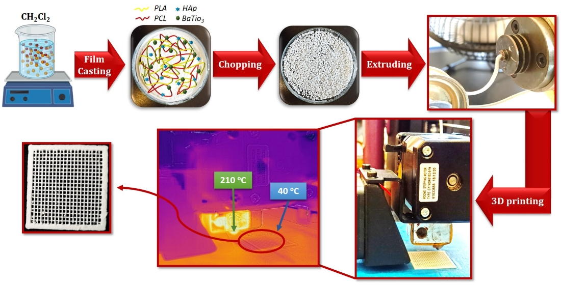
2.2. Fabrication of Filaments

Composite films with two different fillers contents (10 and 20 phr) of HAp and/or BT were prepared by using the solvent casting method [34]. The appropriate amounts of PLA and PCL were dissolved in dichloromethane and next HAp and/or BT powders were added under magnetic stirring. The suspension remained under stirring for 30 min and was next transferred into a 10 cm diameter Petri Dish and dried overnight. The dry film was cut into 4 × 4 mm flakes. Next, the flakes were fed into a single screw filament extruder’s hopper (Felfil, Turin, Italy). Composite filaments with dimensions of 1.74 ± 0.15 mm were produced using a 1.75 mm nozzle while the extrusion temperature ranged from 172 to 175 °C and the screw speed set at 6 rpm.

2.3. Bioscaffold Design and Fabrication

The 3D bioscaffolds were designed using TinkerCad 3D Design software. Next, the file was imported to the slicer software Cura (version 4.3.0). The dimensions of the object were set to 25 × 25 mm with a layer height of 0.2 mm and a total height of 0.8 mm. The printing architecture was set at rectilinear mode. Finally, 3D composite bioscaffolds were manufactured using a commercial fused deposition modeling (FDM) 3D printer (Wanhao, Duplicator i3 Plus) with a nozzle diameter of 0.4 mm. The nozzle temperature which controls the filament extrusion was set at 210 °C and the bed temperature at 40 °C.

2.4. Characterization of the Filaments and the 3D-Printed Objects

Thermal characterization was performed using Differential Scanning Calorimetry (DSC) and Thermogravimetric Analysis (TGA). For the DSC measurements, about 3 mg of samples were placed in aluminum crucibles, next were sealed hermetically, and were tested in a Q200 (TA Instruments, New Castle, DE, USA) apparatus from 25 to 300 °C at a heating rate of 10 °C/min and under nitrogen atmosphere at a flow rate of 50 mL/min. TGA measurements were conducted with a TG Q500 instrument (TA Instruments, New Castle, DE, USA). In the case of filaments testing, approximately 45 mg mass obtained from five different sites of each filament was placed in a platinum pan and heated over a temperature range from 25 to 900 °C at a heating rate of 10 °C/min, under synthetic airflow of 50 mL/min.
The morphological characteristics of the fillers, filaments, and the printed products were examined with Scanning Electron Microscope (SEM) using a Zeiss SUPRA 35VP instrument (Zeiss, Oberkochen, Germany) at an acceleration voltage of 10 kV equipped with an energy dispersive X-ray (EDX) analysis system. Samples were mounted on aluminum stubs using a conductive silver paste (RS 186-3600) and gold-coated before the examination. Furthermore, HAp crystals were examined using Transmission Electron Microscopy (TEM) (JEM 2100, JEOL, Akishima-Shi, Japan). The size of the crystals was measured from the corresponding SEM or TEM images using the image analysis software ImageJ.
The purity of raw materials and the crystallinity of filaments and printed objects were assessed by Powder X-ray Diffractometry (XRD) by using a D8 Advance instrument (Bruker AXS, Karlsruhe, Germany). Data were acquired with Ni-filtered CuKa1 radiation, operating at 40 kV and 40 mA at a scanning speed of 0.6 s/step and a step size of 0.02°. Phase identification was done by the Bruker software Eva.
Attenuated Total Reflection-Fourier Transform Infrared (ATR-FTIR) spectroscopy applied to assess possible interactions between polymers or polymers and filler materials. The spectra were recorded using an IRTracer-100 (Schimadzu, (Shimadzu, Tokyo, Japan) FTIR spectrometer equipped with the ATR accessory MIRacle™ Single Reflection (Madison, WI, USA). The spectra were acquired after 50 scans at a resolution of 4 cm−1 and in the spectral range between 550 and 4000 cm−1.
Tensile strength tests were carried out at room temperature on pure PLA and PLA/PCL filaments using an Instron universal testing machine (Instron 5582, Norwood, MA, USA) at a crosshead displacement rate of 5 mm/min. Tensile mechanical properties were calculated as a mean value of five specimens for each composition. Piezoelectric measurements were performed by a PM300 piezometer (Piezo Test LTD, London, UK). The longitudinal piezoelectric coefficient (d33) was measured by applying a force of 0.25 N at a frequency of 110 Hz.
Electrical response of nanocomposites was examined through Broadband Dielectric Spectroscopy (BDS) in the frequency range from 0.1 Hz to 10 MHz, using an Alpha- N Frequency Response Analyzer and a BDS 1200 dielectric cell both supplied by Novotherm System (Novocontrol Technologies, Hundsagen, Germany). The temperature set at 37 °C and was controlled by a Novotherm System. The number of measuring points during each frequency scan were 70. The calibration procedure was open terminal auto calibration as suggested by the Frequency Response Analyzer’s manufacturer.

3. Results and Discussion

3.1. Morphological and Structural Characterization of Fillers

Figure 1 depicts the morphological characteristics and the structural characterization of HAp and BT. Synthetic hydroxyapatite powder is composed of needle-like crystals with a mean length of 138.1 ± 16.4 nm and a width of 14.8 ± 2.2 nm (Figure 1a). The XRD pattern of HAp fits with the standard JCPDS 9-432 diffractogram showing that no other impurities are present (Figure 1b). The BT crystals showed a roughly round morphology. Their mean size was calculated at 0.76 ± 0.16 μm (Figure 1c). The diffraction peaks of barium titanate confirmed the presence of the tetragonal phase (Figure 1d). The tetragonal phase is characterized by the characteristic splitting of the diffraction peaks between 44° and 46° corresponding to (002) and (200) planes (Figure 1d insert) [35].

3.2. Mechanical Properties

Composite filaments constituted of PLA/10-10 were fragile and broken between the extruder gears making the 3D printing process impossible. To overcome this problem PCL at a quantity of 30% was added as a plasticizer. Figure 2 shows characteristic stress–strain (%) curves of PLA, PLA/PCL, and PLA/PCL/10-10 filaments. In all curves, the characteristics of elastic and plastic regions are observed while the values of maximum tensile strength, elongation at break, and fracture stress are clearly shown. The obtained data values are summarized in Table 1. The obtained value of Elastic Modulus at 2.2 GPa for pure PLA specimens is in good agreement with the values reported in the literature [36]. The mechanical behavior of PLA/PCL/10-10 is also shown in Figure 2. It is shown that the response of the filament containing PCL is different than the neat PLA. The Elastic Modulus is lower, the specimen fractures at lower strength, and after the maximum value necking deformation takes place. The above behavior shows that PCL acts as a plasticizer. This role is also emerged in the next paragraphs describing the DSC results in which the thermal properties of the PLA/PCL blends are presented.

3.3. Thermogravimetric Analysis

Thermogravimetric Analysis (TGA) is used to study the thermal stability of all preparations and to calculate the mass of fillers in composite filaments in comparison with the loaded amount. Figure 3 shows the TGA thermograms of all samples while the insert depicts the differential gravimetric analysis thermograms (DTGA) in the range from 250 to 450 °C which corresponds to the main thermal transition. The TGA graph of pure hydroxyapatite shows a continuous mass loss with a value of 3.1% at 550 °C. The mass loss is associated with absorbed water up to 200 °C, while at the range 200–400 °C it is due to the removal of lattice water. Mass loss in the range 200–550 °C is associated with the decomposition of hydrogen phosphate ions (HPO42−) into pyrophosphate ions (P2O74−) [37,38]. In contrast, the mass loss of pure BT at 550 °C is less than 0.2%.
The TGA and DTGA thermograms of neat PLA and PCL pellets together with the PLA/PCL filament are shown in Figure S1. In the case of pure PLA pellets, a single sharp peak occurs at 366.7 °C and is due to polymer degradation. The respective curve for the PCL pellets is obtained at 409.2 °C. The respective temperatures for the sample PLA/PCL are located at 360.3 and 394.2 °C. Previous works also reported that PLA and PCL thermally degrade also in a single step [39,40].
To compare the relative thermal stability between samples, the temperature in which the loss of total mass was 50% (T50%) was chosen. The results are listed in Table 2. It can be seen that the presence of HAp as filler or in combination with BT, especially at high loading amounts, improves the thermal stability of the composite filament. Data obtained from the DTGA curves corroborate the increasing thermal stability of the composites at high loading values.
Production of composite filaments can be performed using a twin-screw extruder with different heating zones. In this case, raw materials are mixed with the fillers into the hooper, and the composite filament finally exits from the orifice of the extruder’s nozzle. However, in the case of a single screw extruder, fabrication of homogenous composite filaments is usually difficult. To overcome this problem, different techniques have been developed. A common method is based on the film casting technique. The film casting technique using DCM as a solvent has also been successfully used by other researchers [20,41,42]. Results in Table 2 show that the calculated amount of HAp and BT is close to the initial loading. It should be noted that duplicate measurements were conducted at selected formulations and the mass difference between the same composition specimens at 550 °C was less than 1.2%. TGA results using the same method to prepare PLA/HAp filaments exhibited a deviation of about 1% to the loading concentration [42]. Other methods include the solvent-free method in which HAp is mixed with melted PLA, next cooled and shaped in pellets, and then the resulting pellet is cut into pieces and fed the extruder [43].

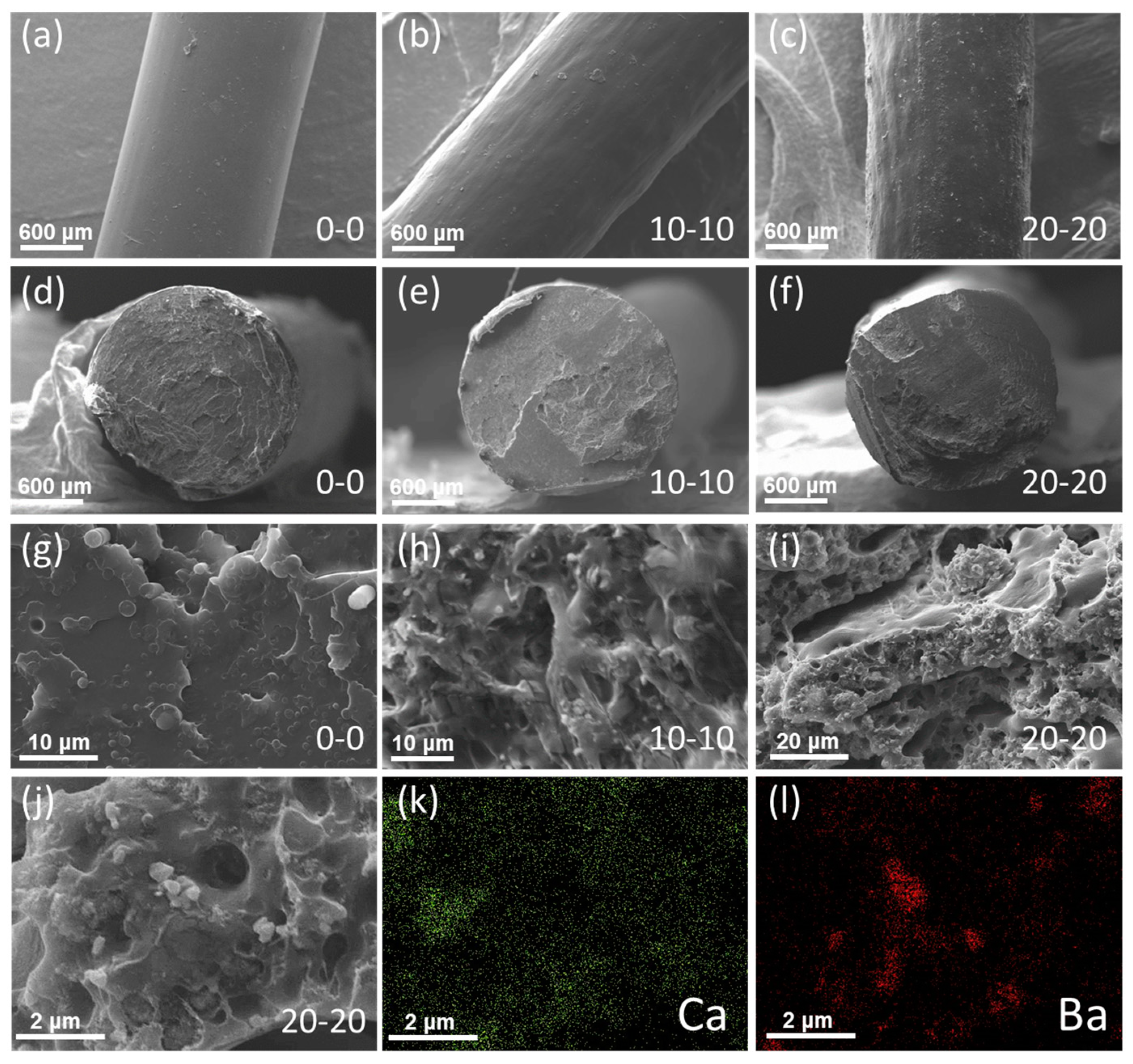
3.4. Scanning Electron Microscopy

Figure 4 shows the external and internal morphological characteristics of neat PLA/PCL and representative composite filaments. The external surface is characterized by a smooth texture, while in the case of HAp/BT/20-20 some tiny particles are observed (Figure 4a–c). The cross-section of the respective filaments also exhibits a homogenous structure (Figure 4d–f). In the case of pure PLA/PCL filaments, the cross-section images taken at higher magnification show the presence of droplets dispersed in the continuous phase (Figure 4g). The droplets can be attributed to PLA particles distributed in the PLA matrix [44]. Figure 4h,i show a homogenous distribution of particles in the polymeric matrix. A representative cross-section image of the PLA/PCL/20-20 composite filament is depicted in Figure 4j and the respective EDX mapping images for Ca and Ba are shown in Figure 4k,l. It can be observed that HAp and BT exhibit good dispersion in the polymeric matrix.
Figure 5 shows SEM images and digital photos (insert) of PCL/PLA and PCL/PLA/20-20 fabricated scaffolds. The neat PLA/PCL samples show a smooth surface while in the case of composites the surface exhibits a rough structure due to the presence of the fillers. The existence of roughness is beneficial since the performance of a biomaterial depends on its surface properties and topography [10]. It has been reported that surface properties such as roughness and surface energy enhance cell cellular proliferation and adhesion [45].
A regular array of square macropores is observed in both cases. The dimensions of the pores and the printed lines were measured from twenty SEM images using the image analysis program ImageJ. It was found that in the case of PLA/PCL objects, the mean pore size was 850.4 ± 48.5 μm while the mean diameter of the printed lines was measured at 393.3 ± 51.8 μm. Similar results were taken in the case of composite specimens. In the case of the PLA/PCL/10-10 objects, the values were 822.3 ± 19.6 μm and 397.2 ± 58.0 μm, respectively. The line width is close to the nozzle diameter which is 0.4 μm. However, the mean pore size is lower than the theoretical design in the 3D pattern, which is about 1.1 μm. This can be attributed to the deformation of the polymeric melt due to the low melting point of PCL. However, optimization of parameters such as flow rate and printing speed can lead to more precise printed pores in comparison with the designed 3D pattern.

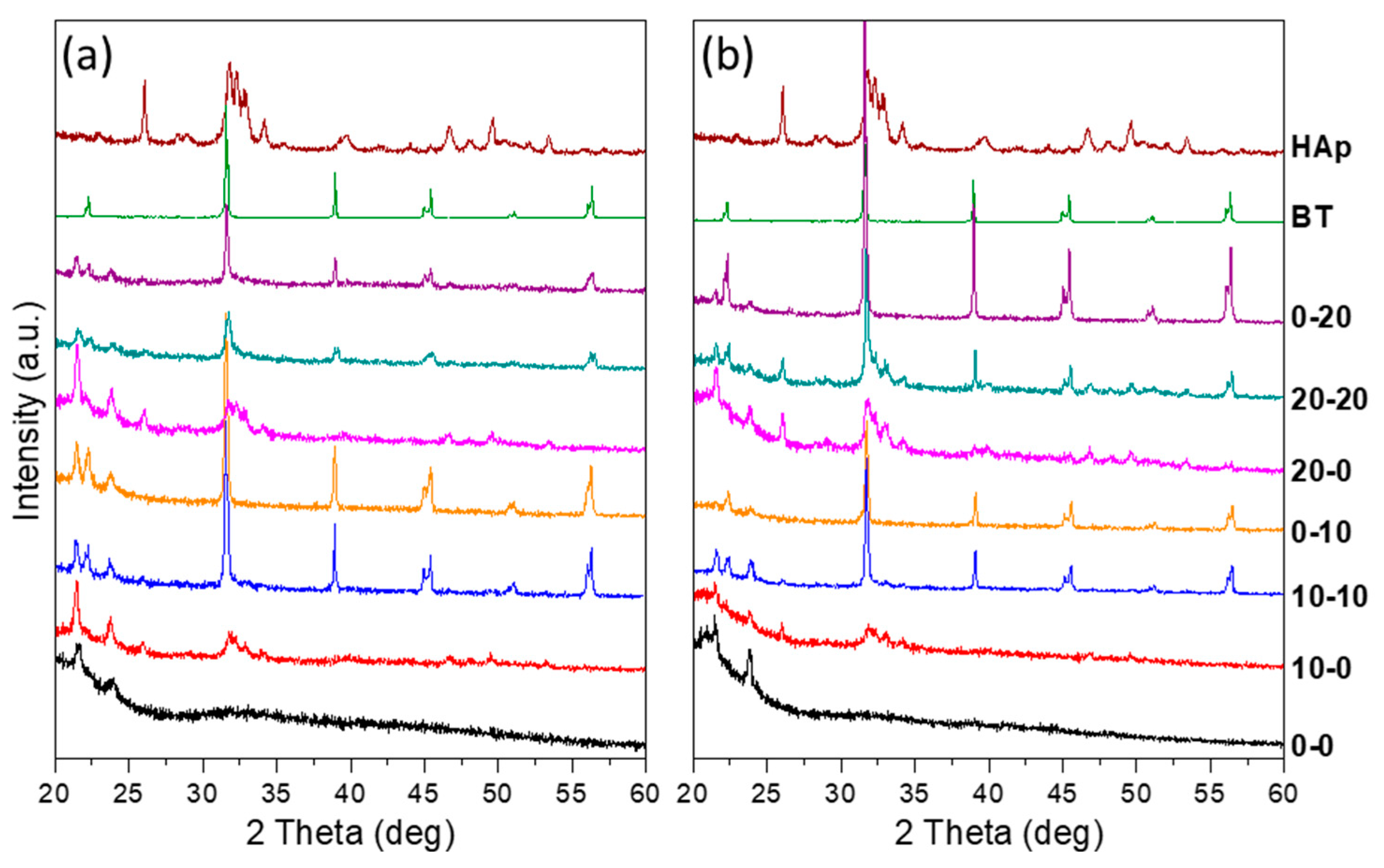
3.5. X-ray Diffraction

The powder diffraction patterns of raw materials, filaments, and 3D printed composites are shown in Figure 6. Patterns containing BT show a high-intensity peak at 31.5° assigned to (110) planes. In the case of HAp/BT composites, the above peak suppresses the diffraction peaks assigned to the presence of HAp since the highest intensity peak of HAp appears at 31.7°. It is interesting to note that in both types of samples, BT exhibits the characteristic double peak in the range of 44° to 46°. This indicates that after two thermal treatments of BT that correspond to the preparation of the filaments and the 3D printing objects, the transition of tetragonal to a cubic structure at 120 °C is reversible.
Figure S2 shows the XRD patterns of all polymeric materials without the presence of fillers. The pattern of PLA shows a broad peak at about 15–16° indicating that PLA exist in orthorhombic structure [46,47,48]. It is interesting to note that PLA shows the same broad peak in filaments as well as in the printed objects, indicating that thermal treatment does not influence its crystallinity. The PCL pattern depicts two intense peaks at 21.4° and 23.8° that correspond to the (100) and (200) planes, respectively, belonging to the orthorhombic structure [49,50]. The above diffraction peaks of PCL are also present in the filaments and in the printed objects.

3.6. Attenuated Total Reflection-Fourier Transform Infrared Spectroscopy

Attenuated Total Reflection-Fourier Transform Infrared spectroscopy (ATR-FTIR) was performed for the structural characterization of raw materials, as well as the filaments and the printed specimens. The FTIR spectrum of pure BaTiO3 (Figure 7a) shows a strong absorption peak at 551 cm−1 due to the vibration of Ti-O bond [51]. The spectrum of HAp shows an intense broad band at 950–1100 cm−1, with the maximum at 1022 cm−1. This is due to stretching vibrations (ν1 at 960 cm−1, ν3 at 1022 cm−1, and ν3 at 1088) of the phosphate groups in HAp. The double band at 559–602 cm−1 is also associated with bending vibrations (ν4 at 559 cm−1 and 602 cm−1) of the phosphate groups. The peak at 632 cm−1 is assigned to libration mode of hydroxyl group [52,53].
Regarding the neat polymeric materials, PLA and PCL (Figure 7b) have the same functional group (carbonyl, C=O) in their structure. The FTIR spectrum of PCL shows the characteristic peak at 1724 cm−1 due to carbonyl stretching vibration, while in the case of PLA the respective peak is located at 1751 cm−1. The spectrum of PCL also shows a characteristic band at 1238 cm−1 assigned to the asymmetric C-O-C stretching vibration. The peaks at 1165 and 1292 cm−1 are assigned to C-O and C-C stretching vibrations in the amorphous and crystalline state, respectively [54].
The FTIR spectrum of PLA, except the carbonyl peak, is characterized by peaks located at 868 cm−1 due to C-C stretching vibrations. The absorption bands at 868 and 754 cm−1 are characteristic for amorphous and crystalline states, respectively. The bands at 1268, 1182, 1130, and 1042 cm−1 are assigned to C-O stretching vibrations. Peaks at 1362, 1454, and 1382 cm−1 are assigned to C-H deformation including symmetric and asymmetric bending vibrations [55,56,57]. The assessment of the major peak of HAp at 1022 cm−1 in composite materials is not possible due to the overlapping with bands assigned to polymeric components (Figure 7c,d). The presence of HAp in the composites filaments or printed objects is confirmed by the absorption peaks at 559 and 602 cm−1; however, they are hardly observed. In the case of BT containing composites, an obscure broad peak at the edge of the spectrum can be observed. Comparing the spectra of composite materials with the neat or PLA/PCL samples, there are no significant shifts in absorption bands of the functional groups. This indicates that there is no chemical interaction between PLA and PCL or between fillers and polymeric matrices. It should be noted also that no evidence of thermal decomposition of PLA and PCL was observed since as previously reported both polymers decompose at temperatures much higher than 210 °C, which is the temperature of the nozzle orifice in 3D printer.

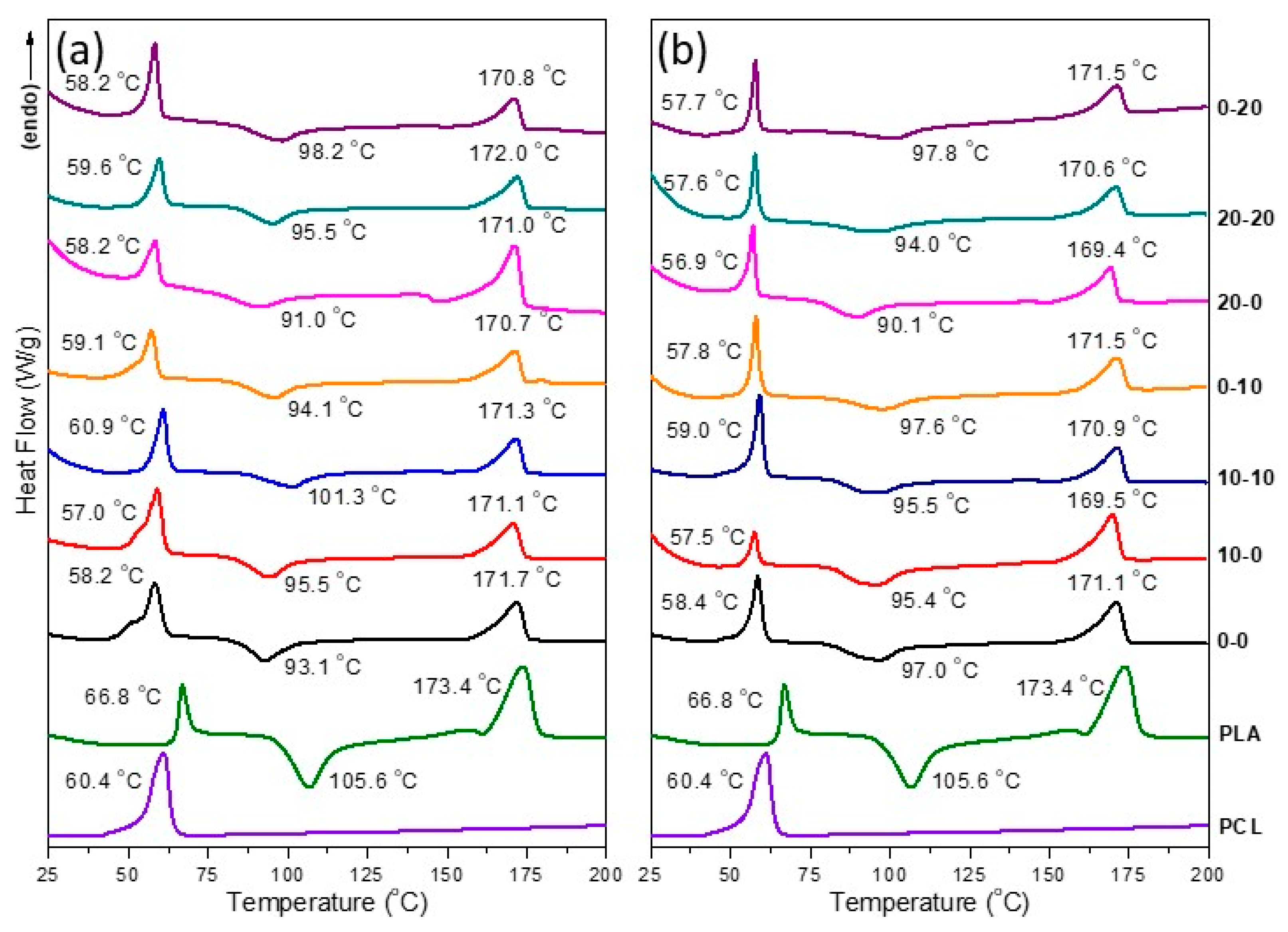
3.7. Differential Scanning Calorimetry

Differential Scanning Calorimetry was used to characterize all products and raw materials. The results of the first heating runs are shown in Figure 8. PLA pellets show an endothermic peak at 60.8 °C that corresponds to the glass transition temperature (Tg), an exothermic cold crystallization peak (Tc) at 106.6 °C, while the endothermic peak at 173.4 °C corresponds to the melting point (Tm). The melting point peak shows an asymmetrical shape due to overlapping peaks. In the case of PLA, this can be attributed to two different lamellae structures with different thicknesses. The thinner lamellae melt at a lower temperature than the wider counterpart. Another explanation is based on the melting-recrystallization mechanism in which the lower melting point is due to the initial amorphous phase, which is transformed, resulting in crystalline lamellae with a higher melting point [58]. Dichtl et al. reported the thermal transition temperatures of 3D printed objects manufactured using the FDM technique. Using commercial PLA filament, the glass transition, cold crystallization, and melting temperatures were measured at 57.8 °C, 127.8 °C, and 156.8 °C, respectively. These differences in comparison with the values measured in the present manuscript can be attributed to the differences in molecular weight or the presence of additives used in commercial filaments [59].
The thermal behavior of PCL pellets in the range between 25 to 200 °C presents a strong endothermic peak at 60.8 °C that corresponds to the melting point. The melting point of PCL is a crucial parameter to set the printing bed temperature. In our case, the bed temperature was set at 40 °C to eliminate PCL deformation of the printed parts. The DSC thermographs of PLA/PCL filaments and printed specimens show a decrease in Tg temperature of PLA in comparison with the neat PLA pellets. This shift can be attributed to the plasticizing effect of PCL [60].
Comparing the DSC graphs of filaments (Figure 8a) and printing objects (Figure 8b), the data obtained from the melting point peak show no significant changes. However, it is interesting to note that the cold crystallization temperature (Tc) of PLA is decreasing in PLA/PCL blends (sample 0-0) as well as in the presence of fillers, indicating that both act as nucleators and therefore the nucleation occurs at lower temperatures. The enhancement of the nucleation process in PLA in the presence of PCL has been reported previously [61].

3.8. Piezoelectric Measurements

The longitudinal piezoelectric coefficient (d33) was measured for all 3D printed specimens. Figure 9 shows the dependence of the piezoelectric coefficient as a function of HAp/BT composition. It can be seen that both HAp and BT increase the d33 value of the specimens. However, the presence of BT increases the d33 to much higher values than the respective samples containing HAp. All measured values are close to the reported values regarding HAp/BT composite or bone measurements. In particular, Zhang et al. prepared porous composite scaffolds with defined porosity and architecture. The piezoelectric coefficient of the samples HAp30/BT70 and HAp10/BT90 were 1.2 and 2.8 pC/N [62]. In another study, the d33 value of HAp/BT bioceramics was increased to a value of 6.8 pC/N by increasing the BT content to 100% [63]. Other works on 3D printed HAp/BT bioceramics report a maximum value of d33 at 3.08 pC/N. More specifically, piezoelectric properties of 3D printed HAp/BT porous bioceramic scaffolds were determined at different polarization conditions. Composition of scaffolds was 68% wt BT, 18% wt HAp, and 14% wt polyethylenemethacrylate before the sintering process [64].
Regarding the piezoelectric properties of bones, early studies reported a d33 value of 0.03 pC/N for horse femur and 6.6 pC/N for wet bovine bone tissue at pH = 5 [65,66]. Marino and Gross compared the piezoelectric properties of three hard tissues. They report values of piezoelectric constants of cementum, dentin, and bone at 0.027, 0.028, and 0.22 pC/N, respectively [67].

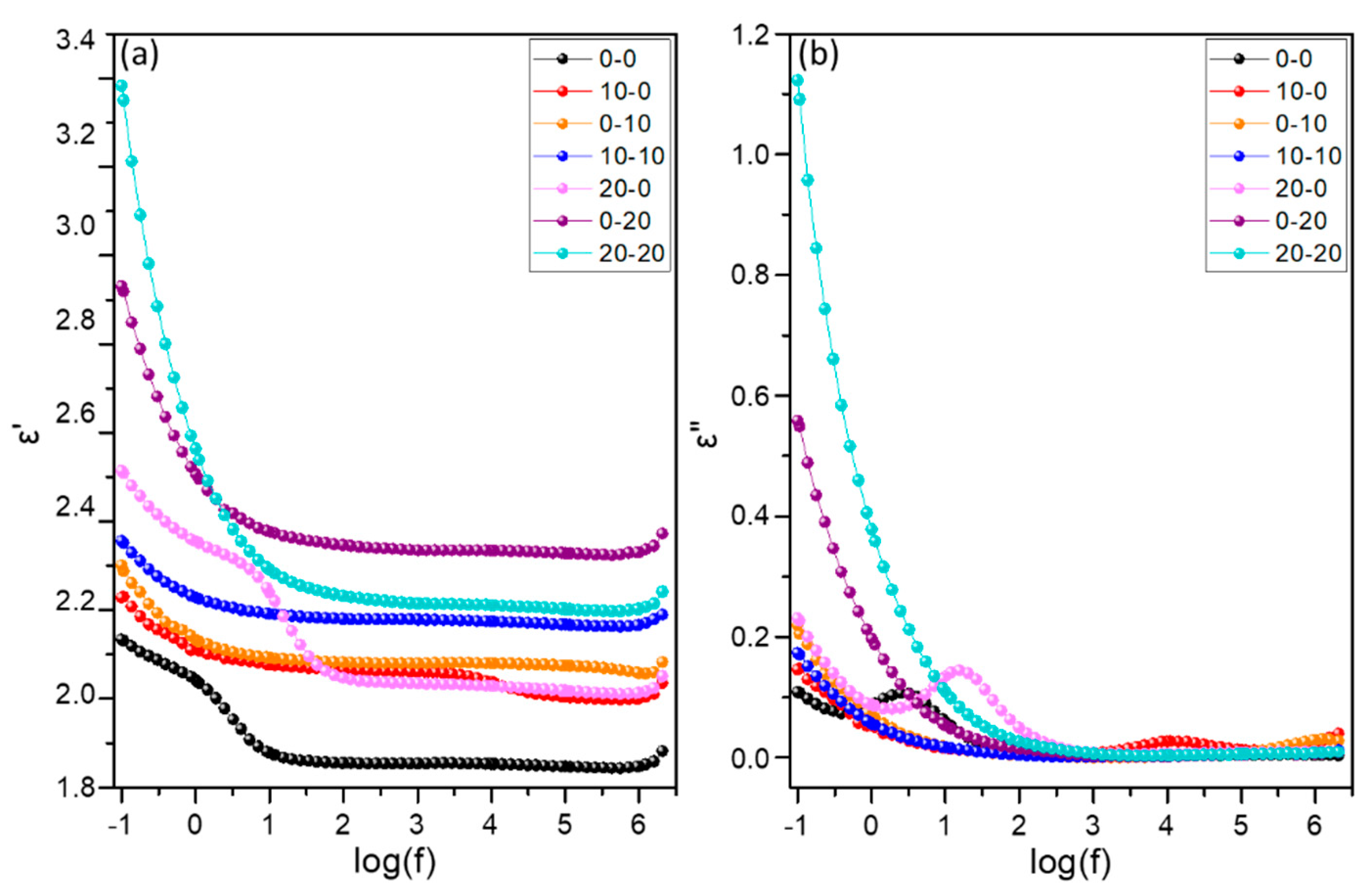
3.9. Dielectric Properties

In this study, the combination of the bioactive properties of HAp with a piezoelectric and high permittivity ferroelectric material, such as BT, was attempted. Figure 10 depicts the variation of the real and imaginary parts of dielectric permittivity with frequency at 37 °C, for all the types of the examined systems. The influence of the reinforcing phase becomes evident via the enhancement of (ε′) with filler content. The real part of dielectric permittivity increases with frequency diminishing for constant temperatures. This is expected since epsilon prime reflects the level of the achieved polarization. When the frequency is low, permanent and induced dipoles acquire sufficient time to align themselves parallel to the applied field. Figure 10 denotes that the effect of BT inclusions is more pronounced with respect to the effect of HAp.
In general, it is normally observed that the dielectric constant decreases as the frequency increase until a constant plateau value; this maximum value depends on the fact that beyond a certain frequency of the electric field, the dipoles are not affected by the alterations on the field. In the case of ionic crystals (e.g., hydroxyapatite crystal structure), the total polarization is electronic and ionic in nature. The hydroxyapatite crystal structure consists of vertically aligned OH ions along the c-axis and Ca2+ and PO43− ions. This dipole moment of the hydroxyl ions is mainly responsible for the dielectric nature of hydroxyapatite. As in most cases, at low frequencies, polarization is fairly affected by the alterations of the field but at high frequencies, the heavy charge of positive and negative ions cannot follow the field variations; the dipole moment of the hydroxyl ions is unaffected by alterations on the field and therefore polarization decreases, resulting in the decrease of ε′.
The values of ε′ of the reinforced with HAp composites are attributed to the dipole moment of hydroxyl ions in HAp [68,69]. Concerning a binary system of two components varying significantly in permittivity values, one should expect that the permittivity of the whole system should increase monotonically with the concentration of the high permittivity constituent. Since dielectric permittivity of BT is much higher than that of PLA/PCL and HAp, the recorded behavior for the filler concentration up to 20 HAp/20 BT, in Figure 10 is quite understandable.
Specimens with the highest BT content exhibit relatively high values of losses (ε″), although the losses of the specimens with lower BT concentration can be considered as low. It could suggest that the employed fabrication procedure via 3D printing appears to be beneficial upon the reduction of dielectric losses.
Marino et al. measured the dielectric properties of bones containing different amounts of water in a frequency range from 105 to 103 Hz. The dielectric constant of the human cortical bone has been found to a very sensitive function of water content. The dielectric constant of dry human cortical bone is around 10. The measured dielectric constant of dry bone values is on average 5.7–6.5 [70]. Furthermore, composite scaffolds with potential applications in bone tissue engineering composed of chitosan and HAp prepared by coprecipitation from aqueous solutions. Dielectric permittivity measurements at 1 MHz, 1000 kHz, and 10 kHz are in the same range with values reported in the present study [71]. Finally, since polarization is proportional to the real part of dielectric permittivity (ε′) high values of ε′ results higher polarization in bioscaffolds and therefore can help bone regeneration.

4. Conclusions

In conclusion, 3D printed multifunctional PLA/PCL-based bioscaffolds that combine the bioactivity of HAp and the piezoelectricity of BT were fabricated using the FDM 3D printing technique. The filaments and the constructs were characterized in terms of morphology, structure, and thermal properties. Composite filaments were produced in a single screw extruder using flakes formed by the solvent casting method. The amount of fillers that was measured was in good agreement with the initially loaded amount. Additionally, it was found that the addition of PCL in the PLA matrix increases the elasticity of the filaments and influences their thermal properties by lowering the glass transition temperature of PLA. The used formulations produced 3D specimens with precise shape and structure. Morphological studies showed a good distribution of the fillers in the polymeric matrix. In this study, piezoelectric measurements were performed in the 3D constructs and the obtained values revealed that the composite scaffolds exhibited piezoelectric coefficient (d33) values close to the human bone. The incorporation of the HAp and BT nanoparticles significantly enhances the dielectric properties of the examined systems, while inducing their functional behavior. Dielectric permittivity increases with filler content and reduces rapidly with frequency. It is evident that all reinforced systems exhibit higher values of ε′ in comparison with PLA/PCL. In addition, the sample with 20 HAp/20 BT content exhibit highest dielectric permittivity values. This study provides fundamental knowledge on the formation and characterization of multifunctional scaffolds based on bioactivity and piezoelectricity. Although the obtained results are very promising for possible applications as bone defect fillers in the skeletal system, more research is needed to evaluate their in vitro and in vivo behavior. For example, cell viability and proliferation experiments or deeper studies are needed to check their in vitro biocompatibility.

Supplementary Materials

The following are available online at https://0-www-mdpi-com.brum.beds.ac.uk/article/10.3390/app11094253/s1, Figure S1: TGA and DTGA (insert) graphs of neat PLA and PCL pellets and PLA/PCL filaments, Figure S2: XRD graphs of raw polymers and pure polymeric filaments and 3D constructs.

Author Contributions

Conceptualization, N.B.; Investigation, E.M., A.C.P. and N.B.; Methodology, E.M., A.C.P. and N.B.; Validation, E.M., A.C.P. and N.B.; Writing—original draft, N.B.; Writing—review and editing, N.B., E.M. and A.C.P. All authors have read and agreed to the published version of the manuscript.

Funding

This research is co-financed by Greece and the European Union (European Social Fund—ESF) through the Operational Programme “Human Resources Development, Education and Lifelong Learning 2014–2020” in the context of the project “Development of smart bone implants using the 3D printing technique” (5049388).

Institutional Review Board Statement

Not applicable.

Informed Consent Statement

Not applicable.

Data Availability Statement

The data presented in this study are available on request from the corresponding author.

Acknowledgments

The authors gratefully acknowledge Mary Kollia and the Laboratory of Electron Microscopy and Microanalysis, School of Natural Sciences, University of Patras for the TEM measurements.

Conflicts of Interest

The authors declare no conflict of interest.

References

  1. Fernandez de Grado, G.; Keller, L.; Idoux-Gillet, Y.; Wagner, Q.; Musset, A.M.; Benkirane-Jessel, N.; Bornert, F.; Offner, D. Bone substitutes: A review of their characteristics, clinical use, and perspectives for large bone defects management. J. Tissue Eng. 2018, 9. [Google Scholar] [CrossRef] [Green Version]
  2. Damien, C.J.; Parsons, J.R. Bone graft and bone graft substitutes: A review of current technology and applications. J. Appl. Biomater. 1991, 2, 187–208. [Google Scholar] [CrossRef]
  3. Haugen, H.J.; Lyngstadaas, S.P.; Rossi, F.; Perale, G. Bone grafts: Which is the ideal biomaterial? J. Clin. Periodontol. 2019, 46, 92–102. [Google Scholar] [CrossRef]
  4. Alexopoulou, M.; Mystiridou, E.; Mouzakis, D.; Zaoutsos, S.; Fatouros, D.G.; Bouropoulos, N. Preparation, characterization and in vitro assessment of ibuprofen loaded calcium phosphate/gypsum bone cements. Cryst. Res. Technol. 2016, 51, 41–48. [Google Scholar] [CrossRef]
  5. Pryor, L.S.; Gage, E.; Langevin, C.-J.; Herrera, F.; Breithaupt, A.D.; Gordon, C.R.; Afifi, A.M.; Zins, J.E.; Meltzer, H.; Gosman, A.; et al. Review of Bone Substitutes. Craniomaxillofac. Trauma Reconstr. 2009, 2, 151–160. [Google Scholar] [CrossRef] [PubMed] [Green Version]
  6. Andriotis, O.; Katsamenis, O.L.; Mouzakis, D.E.; Bouropoulos, N. Preparation and characterization of bioceramics produced from calcium phosphate cements. Cryst. Res. Technol. 2010, 45, 239–243. [Google Scholar] [CrossRef]
  7. Profeta, A.; Huppa, C. Bioactive-glass in Oral and Maxillofacial Surgery. Craniomaxillofac. Trauma Reconstr. 2016, 9, 1–14. [Google Scholar] [CrossRef] [PubMed] [Green Version]
  8. Hoque, J.; Sangaj, N.; Varghese, S. Stimuli-Responsive Supramolecular Hydrogels and Their Applications in Regenerative Medicine. Macromol. Biosci. 2019, 19, 1–16. [Google Scholar] [CrossRef] [Green Version]
  9. Rajabi, A.H.; Jaffe, M.; Arinzeh, T.L. Piezoelectric materials for tissue regeneration: A review. Acta Biomater. 2015, 24, 12–23. [Google Scholar] [CrossRef] [Green Version]
  10. Xia, Y.; Sun, J.; Zhao, L.; Zhang, F.; Liang, X.J.; Guo, Y.; Weir, M.D.; Reynolds, M.A.; Gu, N.; Xu, H.H.K. Magnetic field and nano-scaffolds with stem cells to enhance bone regeneration. Biomaterials 2018, 183, 151–170. [Google Scholar] [CrossRef] [PubMed]
  11. Fanti, A.; Lodi, M.B.; Mazzarella, G. Enhancement of Cell Migration Rate Toward a Superparamagnetic Scaffold Using LF Magnetic Fields. IEEE Trans. Magn. 2016, 52, 1–8. [Google Scholar] [CrossRef]
  12. Wan, Z.; Zhang, P.; Lv, L.; Zhou, Y. NIR light-assisted phototherapies for bone-related diseases and bone tissue regeneration: A systematic review. Theranostics 2020, 10, 11837–11861. [Google Scholar] [CrossRef]
  13. Lavanya, K.; Chandran, S.V.; Balagangadharan, K.; Selvamurugan, N. Temperature- and pH-responsive chitosan-based injectable hydrogels for bone tissue engineering. Mater. Sci. Eng. C 2020, 111, 110862. [Google Scholar] [CrossRef]
  14. Kapat, K.; Shubhra, Q.T.H.; Zhou, M.; Leeuwenburgh, S. Piezoelectric Nano-Biomaterials for Biomedicine and Tissue Regeneration. Adv. Funct. Mater. 2020, 30. [Google Scholar] [CrossRef] [Green Version]
  15. Fukada, E.; Yasuda, I. On the piezoelectric effect of bone. J. Phys. Soc. Jpn. 1957, 12, 1158–1162. [Google Scholar] [CrossRef]
  16. Braden, M.; Bairstow, A.G.; Beider, I.; Ritter, B.G. Electrical and piezo-electrical properties of dental hard tissues. Nature 1966, 212, 1565–1566. [Google Scholar] [CrossRef]
  17. Bassett, C.A.L.; Becker, R.O. Generation of Electric Potentials by Bone in Response to Mechanical Stress obtained in a highly purified state. Science 1962, 137, 1063–1064. [Google Scholar] [CrossRef]
  18. Khan, F.; Tanaka, M. Designing smart biomaterials for tissue engineering. Int. J. Mol. Sci. 2018, 19, 17. [Google Scholar] [CrossRef] [Green Version]
  19. Tandon, B.; Blaker, J.J.; Cartmell, S.H. Piezoelectric materials as stimulatory biomedical materials and scaffolds for bone repair. Acta Biomater. 2018, 73, 1–20. [Google Scholar] [CrossRef] [PubMed] [Green Version]
  20. Belaid, H.; Nagarajan, S.; Teyssier, C.; Barou, C.; Barés, J.; Balme, S.; Garay, H.; Huon, V.; Cornu, D.; Cavaillès, V.; et al. Development of new biocompatible 3D printed graphene oxide-based scaffolds. Mater. Sci. Eng. C 2020, 110, 110595. [Google Scholar] [CrossRef]
  21. Liu, Y.; Zhang, X.; Cao, C.; Zhang, Y.; Wei, J.; Li, Y.J.; Liang, W.; Hu, Z.; Zhang, J.; Wei, Y.; et al. Built-In Electric Fields Dramatically Induce Enhancement of Osseointegration. Adv. Funct. Mater. 2017, 27, 1–9. [Google Scholar] [CrossRef]
  22. Ribeiro, C.; Sencadas, V.; Correia, D.M.; Lanceros-Méndez, S. Piezoelectric polymers as biomaterials for tissue engineering applications. Colloids Surf. B Biointerfaces 2015, 136, 46–55. [Google Scholar] [CrossRef] [Green Version]
  23. Patsidis, A.; Psarras, G.C. Dielectric behaviour and functionality of polymer matrix—Ceramic BaTiO3 composites. Express Polym. Lett. 2008, 2, 718–726. [Google Scholar] [CrossRef]
  24. Patsidis, A.C.; Kalaitzidou, K.; Anastassopoulos, D.L.; Vradis, A.A.; Psarras, G.C. Graphite nanoplatelets and/or barium titanate/polymer nanocomposites: Fabrication, thermomechanical properties, dielectric response and energy storage. J. Chin. Adv. Mater. Soc. 2014, 2, 207–221. [Google Scholar] [CrossRef]
  25. Ciofani, G.; Ricotti, L.; Canale, C.; D’Alessandro, D.; Berrettini, S.; Mazzolai, B.; Mattoli, V. Effects of barium titanate nanoparticles on proliferation and differentiation of rat mesenchymal stem cells. Colloids Surf. B Biointerfaces 2013, 102, 312–320. [Google Scholar] [CrossRef]
  26. Rocca, A.; Marino, A.; Rocca, V.; Moscato, S.; de Vito, G.; Piazza, V.; Mazzolai, B.; Mattoli, V.; Ngo-Anh, T.J.; Ciofani, G. Barium titanate nanoparticles and hypergravity stimulation improve differentiation of mesenchymal stem cells into osteoblasts. Int. J. Nanomed. 2015, 10, 433–445. [Google Scholar] [CrossRef] [Green Version]
  27. Zanfir, A.V.; Voicu, G.; Busuioc, C.; Jinga, S.I.; Albu, M.G.; Iordache, F. New Coll-HA/BT composite materials for hard tissue engineering. Mater. Sci. Eng. C 2016, 62, 795–805. [Google Scholar] [CrossRef]
  28. Li, Z.; Qu, Y.; Zhang, X.; Yang, B. Bioactive nano-titania ceramics with biomechanical compatibility prepared by doping with piezoelectric BaTiO3. Acta Biomater. 2009, 5, 2189–2195. [Google Scholar] [CrossRef]
  29. Zarkoob, H.; Ziaei-Rad, S.; Fathi, M.; Dadkhah, H. Synthesis, characterization and bioactivity evaluation of porous barium titanate with nanostructured hydroxyapatite coating for biomedical application. Adv. Eng. Mater. 2012, 14, 322–329. [Google Scholar] [CrossRef]
  30. Koju, N.; Sikder, P.; Gaihre, B.; Bhaduri, S.B. Smart injectable self-setting monetite based bioceramics for orthopedic applications. Materials 2018, 10, 1258. [Google Scholar] [CrossRef] [Green Version]
  31. Kalsoom, U.; Nesterenko, P.N.; Paull, B. Recent developments in 3D printable composite materials. RSC Adv. 2016, 6, 60355–60371. [Google Scholar] [CrossRef]
  32. Schult, M.; Buckow, E.; Seitz, H. Experimental studies on 3D printing of barium titanate ceramics for medical applications. Curr. Dir. Biomed. Eng. 2016, 2, 95–99. [Google Scholar] [CrossRef]
  33. Tanase, C.E.; Popa, M.I.; Verestiuc, L. Biomimetic bone scaffolds based on chitosan and calcium phosphates. Mater. Lett. 2011, 65, 1681–1683. [Google Scholar] [CrossRef]
  34. Kim, H.; Fernando, T.; Li, M.; Lin, Y.; Tseng, T.L.B. Fabrication and characterization of 3D printed BaTiO3/PVDF nanocomposites. J. Compos. Mater. 2018, 52, 197–206. [Google Scholar] [CrossRef] [Green Version]
  35. Patsidis, A.C.; Psarras, G.C. Structural transition, dielectric properties and functionality in epoxy resin—Barium titanate nanocomposites. Smart Mater. Struct. 2013, 22. [Google Scholar] [CrossRef]
  36. Abeykoon, C.; Sri-Amphorn, P.; Fernando, A. Optimization of fused deposition modeling parameters for improved PLA and ABS 3D printed structures. Int. J. Light. Mater. Manuf. 2020, 3, 284–297. [Google Scholar] [CrossRef]
  37. Liao, C.J.; Lin, F.H.; Chen, K.S.; Sun, J.S. Thermal decomposition and reconstitution of hydroxyapatite in air atmosphere. Biomaterials 1999, 20, 1807–1813. [Google Scholar] [CrossRef]
  38. Lazić, S.; Zec, S.; Miljević, N.; Milonjić, S. The effect of temperature on the properties of hydroxyapatite precipitated from calcium hydroxide and phosphoric acid. Thermochim. Acta 2001, 374, 13–22. [Google Scholar] [CrossRef]
  39. Herrera-Kao, W.A.; Loría-Bastarrachea, M.I.; Pérez-Padilla, Y.; Cauich-Rodríguez, J.V.; Vázquez-Torres, H.; Cervantes-Uc, J.M. Thermal degradation of poly(caprolactone), poly(lactic acid), and poly(hydroxybutyrate) studied by TGA/FTIR and other analytical techniques. Polym. Bull. 2018, 75, 4191–4205. [Google Scholar] [CrossRef]
  40. Su, T.T.; Jiang, H.; Gong, H. Thermal stabilities and the thermal degradation kinetics of poly(ε-caprolactone). Polym. Plast. Technol. Eng. 2008, 47, 398–403. [Google Scholar] [CrossRef]
  41. Jain, S.K.; Tadesse, Y. Fabrication of Polylactide/Carbon Nanopowder Filament using Melt Extrusion and Filament Characterization for 3D Printing. Int. J. Nanosci. 2019, 18, 1–4. [Google Scholar] [CrossRef] [Green Version]
  42. Wu, D.; Spanou, A.; Diez-Escudero, A.; Persson, C. 3D-printed PLA/HA composite structures as synthetic trabecular bone: A feasibility study using fused deposition modeling. J. Mech. Behav. Biomed. Mater. 2020, 103, 103608. [Google Scholar] [CrossRef]
  43. Amnael Orozco-Díaz, C.; Moorehead, R.; Reilly, G.C.; Gilchrist, F.; Miller, C. Characterization of a composite polylactic acid-hydroxyapatite 3D-printing filament for bone-regeneration. Biomed. Phys. Eng. Express 2020, 7, 025007. [Google Scholar] [CrossRef]
  44. Wachirahuttapong, S.; Thongpin, C.; Sombatsompop, N. Effect of PCL and Compatibility Contents on the Morphology, Crystallization and Mechanical Properties of PLA/PCL Blends. Energy Procedia 2016, 89, 198–206. [Google Scholar] [CrossRef] [Green Version]
  45. Hallab, N.J.; Bundy, K.J.; O’Connor, K.; Moses, R.L.; Jacobs, J.J. Evaluation of metallic and polymeric biomaterial surface energy and surface roughness characteristics for directed cell adhesion. Tissue Eng. 2001, 7, 55–70. [Google Scholar] [CrossRef] [PubMed] [Green Version]
  46. Kaczmarek, H.; Nowicki, M.; Vuković-Kwiatkowska, I.; Nowakowska, S. Crosslinked blends of poly(lactic acid) and polyacrylates: AFM, DSC and XRD studies. J. Polym. Res. 2013, 20, 91. [Google Scholar] [CrossRef] [Green Version]
  47. Chu, Z.; Zhao, T.; Li, L.; Fan, J.; Qin, Y. Characterization of antimicrobial poly (lactic acid)/nano-composite films with silver and zinc oxide nanoparticles. Materials 2017, 10, 659. [Google Scholar] [CrossRef] [Green Version]
  48. Miyata, T.; Masuko, T. Morphology of poly (L-lactide) solution-grown crystals. Polymer 1997, 38, 4003–4009. [Google Scholar] [CrossRef]
  49. Baji, A.; Wong, S.C.; Liu, T.; Li, T.; Srivatsan, T.S. Morphological and X-ray diffraction studies of crystalline hydroxyapatite-reinforced polycaprolactone. J. Biomed. Mater. Res. Part B Appl. Biomater. 2007, 81, 343–350. [Google Scholar] [CrossRef]
  50. Bittiger, H.; Marchessault, R.H.; Niegisch, W.D. Crystal structure of poly-ε-caprolactone. Acta Crystallogr. Sect. B Struct. Crystallogr. Cryst. Chem. 1970, 26, 1923–1927. [Google Scholar] [CrossRef]
  51. Sun, D.; Jin, X.; Liu, H.; Zhu, J.; Zhu, Y.; Zhu, Y. Investigation on FTIR spectrum of barium titanate ceramics doped with alkali ions. Ferroelectrics 2007, 355, 145–148. [Google Scholar] [CrossRef]
  52. Ślósarczyk, A.; Paszkiewicz, Z.; Paluszkiewicz, C. FTIR and XRD evaluation of carbonated hydroxyapatite powders synthesized by wet methods. J. Mol. Struct. 2005, 744–747, 657–661. [Google Scholar] [CrossRef]
  53. Destainville, A.; Champion, E.; Bernache-Assollant, D.; Laborde, E. Synthesis, characterization and thermal behavior of apatitic tricalcium phosphate. Mater. Chem. Phys. 2003, 80, 269–277. [Google Scholar] [CrossRef]
  54. Elzubair, A.; Elias, C.N.; Suarez, J.C.M.; Lopes, H.P.; Vieira, M.V.B. The physical characterization of a thermoplastic polymer for endodontic obturation. J. Dent. 2006, 34, 784–789. [Google Scholar] [CrossRef] [PubMed]
  55. Agarwal, M.; Koelling, K.W.; Chalmers, J.J. Characterization of the degradation of polylactic acid polymer in a solid substrate environment. Biotechnol. Prog. 1998, 14, 517–526. [Google Scholar] [CrossRef]
  56. Bouamer, A.; Benrekaa, N.; Younes, A. Characterization of polylactic acid ceramic composites synthesized by casting method. Mater. Today Proc. 2021, 42, 2959–2962. [Google Scholar] [CrossRef]
  57. Popa, E.E.; Rapa, M.; Popa, O.; Mustatea, G.; Popa, V.I.; Mitelut, A.C.; Popa, M.E. Polylactic acid/cellulose fibres based composites for food packaging applications. Mater. Plast. 2017, 54, 673–677. [Google Scholar] [CrossRef]
  58. Gracia-Fernández, C.A.; Gómez-Barreiro, S.; López-Beceiro, J.; Naya, S.; Artiaga, R. New approach to the double melting peak of poly(l-lactic acid) observed by DSC. J. Mater. Res. 2012, 27, 1379–1382. [Google Scholar] [CrossRef]
  59. Dichtl, C.; Sippel, P.; Krohns, S. Dielectric Properties of 3D Printed Polylactic Acid. Adv. Mater. Sci. Eng. 2017, 2017. [Google Scholar] [CrossRef] [Green Version]
  60. Olewnik-Kruszkowska, E.; Kasperska, P.; Koter, I. Effect of poly(ϵ-caprolactone) as plasticizer on the properties of composites based on polylactide during hydrolytic degradation. React. Funct. Polym. 2016, 103, 99–107. [Google Scholar] [CrossRef]
  61. Urquijo, J.; Guerrica-Echevarría, G.; Eguiazábal, J.I. Melt processed PLA/PCL blends: Effect of processing method on phase structure, morphology, and mechanical properties. J. Appl. Polym. Sci. 2015, 132, 1–9. [Google Scholar] [CrossRef]
  62. Zhang, Y.; Chen, L.; Zeng, J.; Zhou, K.; Zhang, D. Aligned porous barium titanate/hydroxyapatite composites with high piezoelectric coefficients for bone tissue engineering. Mater. Sci. Eng. C 2014, 39, 143–149. [Google Scholar] [CrossRef]
  63. Tang, Y.; Wu, C.; Wu, Z.; Hu, L.; Zhang, W.; Zhao, K. Fabrication and in vitro biological properties of piezoelectric bioceramics for bone regeneration. Sci. Rep. 2017, 7, 1–12. [Google Scholar] [CrossRef] [PubMed] [Green Version]
  64. Polley, C.; Distler, T.; Detsch, R.; Lund, H.; Springer, A.; Boccaccini, A.R.; Seitz, H. 3D printing of piezoelectric barium titanate-hydroxyapatite scaffiolds with interconnected porosity for bone tissue engineering. Materials 2020, 13, 1773. [Google Scholar] [CrossRef]
  65. Fukada, E. Piezoelectricity in polymers and biological materials. Ultrasonics 1968, 6, 229–234. [Google Scholar] [CrossRef]
  66. Guzelsu, N.; Donofrio, J. Particle electrophoresis of compact bone tissue. Electromagn. Biol. Med. 1983, 2, 187–196. [Google Scholar] [CrossRef]
  67. Marino, A.A.; Gross, B.D. Piezoelectricity in cementum, dentine and bone. Arch. Oral Biol. 1989, 34, 507–509. [Google Scholar] [CrossRef]
  68. Mahabole, M.P.; Aiyer, R.C.; Ramakrishna, C.V.; Sreedhar, B.; Khairnar, R.S. Synthesis, characterization and gas sensing property of hydroxyapatite ceramic. Bull. Mater. Sci. 2005, 28, 535–545. [Google Scholar] [CrossRef] [Green Version]
  69. Dubey, A.K.; Basu, B.; Balani, K.; Guo, R.; Bhalla, A.S. Dielectric and pyroelectric properties of HAp-BaTiO3 composites. Ferroelectrics 2011, 423, 63–76. [Google Scholar] [CrossRef]
  70. Marino, A.A.; Becker, R.O.; Bachman, C.H. Dielectric determination of bound water of bone. Phys. Med. Biol. 1967, 12, 367–378. [Google Scholar] [CrossRef] [Green Version]
  71. Petrov, I.; Kalinkevich, O.; Pogorielov, M.; Kalinkevich, A.; Stanislavov, A.; Sklyar, A.; Danilchenko, S.; Yovcheva, T. Dielectric and electric properties of new chitosan-hydroxyapatite materials for biomedical application: Dielectric spectroscopy and corona treatment. Carbohydr. Polym. 2016, 151, 770–778. [Google Scholar] [CrossRef] [PubMed]
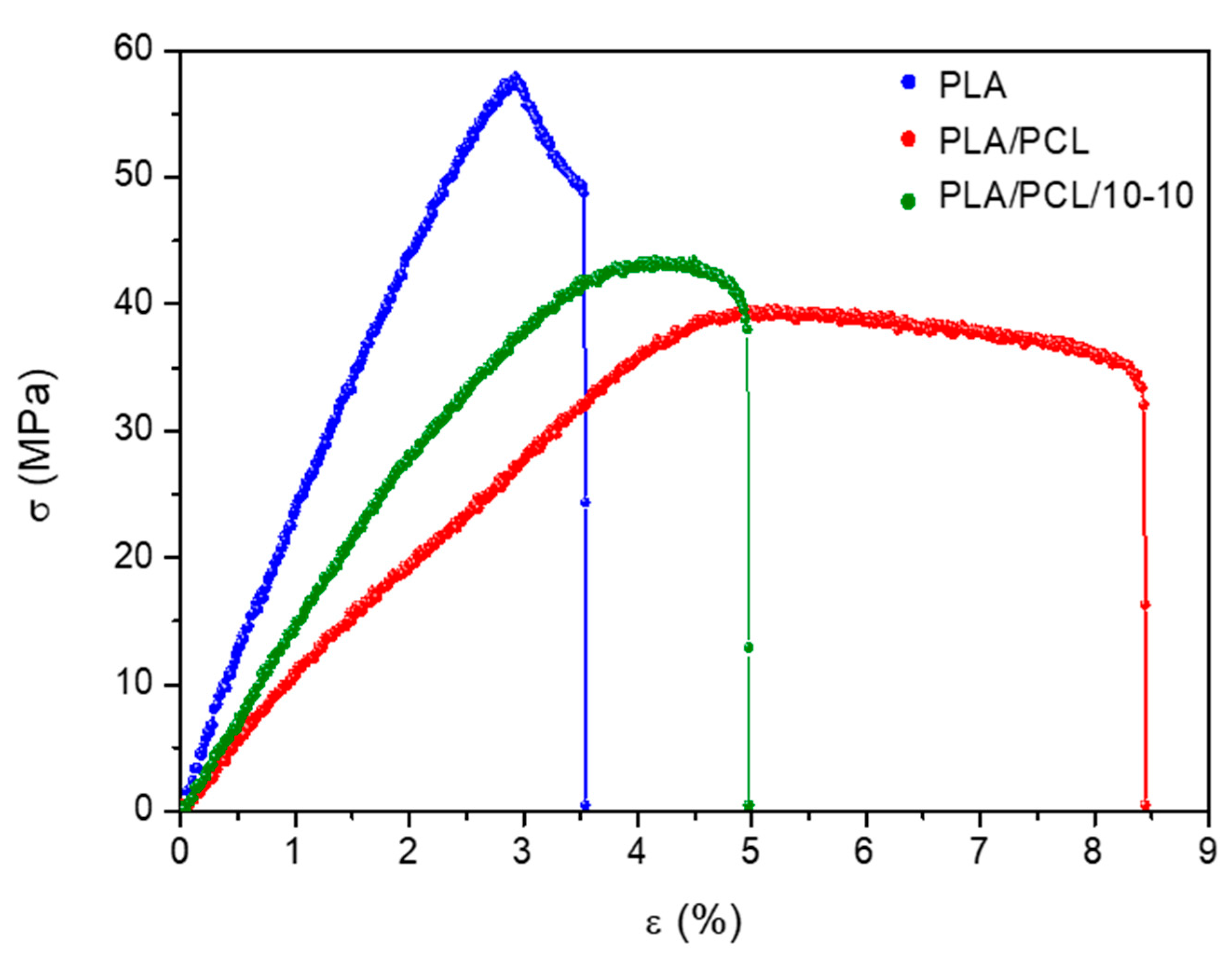
Figure 1. TEM image (a) and XRD pattern (b) of synthetic HAp crystals. SEM micrograph (c) and XRD diffractogram of BT crystals. The standard JCPDS files for HAp and BT are shown in Figures (b) and (d), respectively.
Applsci 11 04253 g001
Figure 2. Stress–strain (%) curves for pure PLA, PLA/PCL, and PLA/PCL/10-10 filaments.
Applsci 11 04253 g002
Figure 3. TGA (a,b) and DTGA (c,d) graphs of neat and composite filaments.
Applsci 11 04253 g003
Figure 4. SEM images: External surface (ac) and cross-section images (di) of neat PLA/PCL, PLA/PCL/10-10, and PLA/PCL/20-20 filaments, respectively. Image (j) shows a cross-section detail of the PLA/PCL/20-20 filament while images (k) and (l) show the elemental mapping for Ca and Ba, respectively.
Applsci 11 04253 g004
Figure 5. SEM images and digital photos (insert) of PCL/PLA (a) and PCL/PLA/20-20 (b) fabricated scaffolds.
Applsci 11 04253 g005
Figure 6. XRD graphs of filaments (a), 3D printed scaffolds (b), and pure HAp and BT powders.
Applsci 11 04253 g006
Figure 7. ATR-FTIR spectra of neat polymers (PLA and PCL) and polymer blends (a), inorganic fillers (HAp and BT) (b), composite filaments (c), and 3D printed scaffolds (d).
Applsci 11 04253 g007
Figure 8. DSC thermograms of filaments (a) and printed specimens (b). Both graphs also contain the thermographs of neat PLA and PCL pellets.
Applsci 11 04253 g008
Figure 9. Piezoelectric coefficient (d33) as a function of HAp/BT composition.
Applsci 11 04253 g009
Figure 10. Real (a) and imaginary (b) parts of dielectric permittivity as a function of frequency at T = 37 °C for all studied systems.
Applsci 11 04253 g010
Table 1. Mechanical properties of pure PLA, PLA/PCL, and PLA/PCL/10-10 filaments.
PLAPLA/PCLPLA/PCL/10-10
Elastic Modulus (GPa)2.2 ± 0.11.2 ± 0.21.4 ± 0.1
Tensile Strength (MPa)57.2 ± 6.241.7 ± 3.745.6 ± 2.5
Elongation at Break (%)4.2 ± 0.76.8 ± 1.65.5 ± 0.8
Fracture Stress (MPa)54.8 ± 6.135.0 ± 5.341.8 ± 3.1
Table 2. TGA and DTGA data of pure and composite filaments.
SampleT50% (°C)DTGA (°C)Mass of Fillers (phr)
LoadedMeasured
PLA/PCL/0-0360.1360.300
PLA/PCL/0-10362.6358.3109.86
PLA/PCL/10-10371.6365.52019.62
PLA/PCL/10-0374.2374.7109.58
PLA/PCL/0-20375.2370.42017.92
PLA/PCL/20-20382.1366.14039.51
PLA/PCL/20-0371.8368.92019.46
Publisher’s Note: MDPI stays neutral with regard to jurisdictional claims in published maps and institutional affiliations.

