
The SXFEL Upgrade: From Test Facility to User Facility
by
 ,
,
Bo Liu
 ,
,
Chao Feng
,
Duan Gu
,
Fei Gao
,
Haixiao Deng
,
Meng Zhang
,
Sen Sun
,
Si Chen
,
Wei Zhang
,
Wencheng Fang
,
Zhen Wang
,
Qiaogen Zhou
,
Yongbin Leng
,
Ming Gu
,
Lixin Yin
,
Qiang Gu
,
Guoping Fang
,
Dong Wang
and
Zhentang Zhao
* Shanghai Advanced Research Institute, Chinese Academy of Sciences, Shanghai 201204, China
*
Author to whom correspondence should be addressed.
Appl. Sci. 2022, 12(1), 176; https://0-doi-org.brum.beds.ac.uk/10.3390/app12010176
Submission received: 23 November 2021
/
Revised: 15 December 2021
/
Accepted: 16 December 2021
/
Published: 24 December 2021
(This article belongs to the Special Issue Latest Trends in Free Electron Lasers)
Abstract
:The Shanghai soft X-ray Free-Electron Laser facility (SXFEL), which is the first X-ray FEL facility in China, is being constructed in two phases: the test facility (SXFEL-TF) and the user facility (SXFEL-UF). The test facility was initiated in 2006 and funded in 2014. The commissioning of the test facility was finished in 2020. The user facility was funded in 2016 to upgrade the accelerator energy and build two undulator lines with five experimental end-stations. The output photon energy of the user facility will cover the whole water window range. This paper presents an overview of the SXFEL facility, including considerations of the upgrade, layout and design, construction status, commissioning progress and future plans.
1. Introduction
Free-electron lasers (FELs), capable of providing high power and tunable coherent radiation, have witnessed an impressive development in the last decades. To date, several X-ray FEL facilities, such as FLASH [1], LCLS [2], SACLA [3], FERMI [4], PAL-XFEL [5], SwissFEL [6], European XFEL [7], SXFEL [8,9,10], LCLS-II [11] and SHINE [12], have been built or are under construction worldwide. Most of these facilities have adopted self-amplified spontaneous emission (SASE) [13,14] and high-gain harmonic generation (HGHG) [15,16] as basic operations modes. In order to generate fully coherent radiation in the X-ray range, several advanced schemes, including echo-enabled harmonic generation (EEHG) [17,18], cascaded HGHG/EEHG [19,20] have been proposed and experimentally demonstrated at NLCTA [21,22,23,24], SDUV-FEL [25,26], FERMI [27,28] and SXFEL [29].
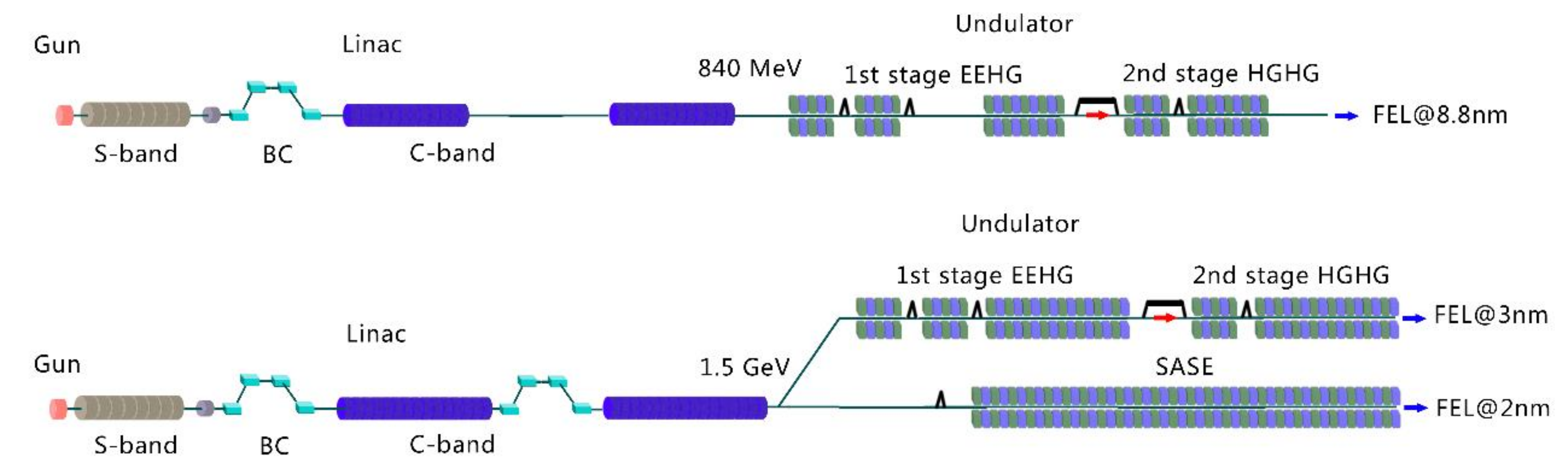
The SXFEL project proceed in two phases, the test facility (SXFEL-TF) and the user facility (SXFEL-UF). The SXFEL-TF has two purposes, including developing high gain FEL technologies and promoting FEL research in China, which can accumulate the indispensable technical experience for constructing and utilizing the hard x-ray FEL facility. The SXFEL-TF was approved by the government and started civil construction in 2014. The construction of the building and the first-round installation were finished in 2016. Then it was followed by several years of alternate construction and commissioning, finally the test facility achieved all the design goals in the summer of 2020, including the demonstration of two-stage HGHG-HGHG cascade and two-stage EEHG-HGHG cascade schemes. Compared to the HGHG-HGHG scheme, the EEHG-HGHG scheme shows better spectral properties, such as narrower bandwidth and better central wavelength stability at 8.8 nm. The output peak power is over 100 MW and pulse duration is about 100 fs. The test facility passed national acceptance at the end of 2020.
The SXFEL user facility is upgraded and integrated based on the test facility, including linac energy upgrade, construction of new undulator line, beamlines, end-stations, experimental hall, etc. The project was funded and the civil construction was started in 2016. The commissioning of the SXFEL-UF started in spring of 2021.
2. Main Parts of the SXFEL User Facility
2.1. Schematic and Parameters
The SXFEL user facility comprises one linac, two undulator lines, two beamlines and five end-stations.
The linac can provide a high-quality electron beam with energy of 1.5 GeV, charge of 0.5 nC, peak current of about 700 A and normalized project emittance of about 1.5 mm·mrad. A beam distribution switchyard lies downstream of the transport line after the linac, distributing the beam to two downstream undulator lines while maintaining the quality of the electron beam. Two undulator lines, a SASE line and a Seeding line, will produce FEL radiation with the shortest wavelength of about 2 nm and 3 nm, respectively. Two helical undulators located at the end of the seeding FEL line aim to provide polarization-controllable, fully coherent radiation pulses.
Two beamlines, located downstream of the undulator lines, measure the pulse energy and the spectral properties of the radiation pulse online, and transport the radiation pulses to the end-stations. Five experimental end-stations, downstream of the whole facility, hold the ability to carry out various experiments including coherent diffraction imaging [30], ultra-fast physics [31], AMO [32], pump-probe [33], etc. The schematic layout of the SXFEL-UF and the SXFEL-TF are given in Figure 1, showing the differences between the test facility and the user facility. The main parameters of the electron beam and the radiation at SXFEL-UF are listed in Table 1.
2.2. Linac
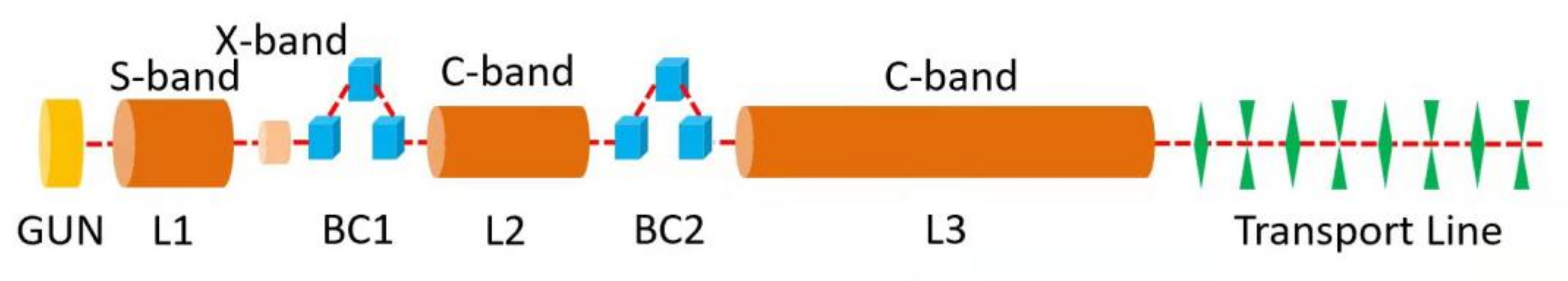
The linac of SXFEL-UF includes a photocathode injector to generate a high-quality electron beam, a laser heater (LH) to suppress the microbunching instability, three main boosting sections (L1, L2 and L3) to accelerate the beam to 1.5 GeV, two-stage chicanes (BC1 and BC2) to compress the beam and the beam transport line for beam matching and transportation. Upgradations are performed including LH, BC2, several C-band accelerating sections and the beam transport line.
In the injector, a temporal Gaussian-like drive laser, instead of the pulse stacking scheme, is adopted to suppress the microbunching instability [34], coordinated with the laser heater system. The 125 MeV electron beam, generated in the S-band injector with a charge of 0.5 nC and pulse duration of about 10 ps, is boosted to 250 MeV in the L1 S-band accelerating section. An X-band linearizer is used to compensate the quadratic term of the energy chirp [35]. The electron beam is then compressed to about 700 A in the downstream bunch compressor chicane (BC1) and accelerated to about 1.5 GeV in C-band L2 and L3, as shown in Figure 2. The second bunch compressor (BC2) is usually not used, aiming to suppress the microbunching instability.
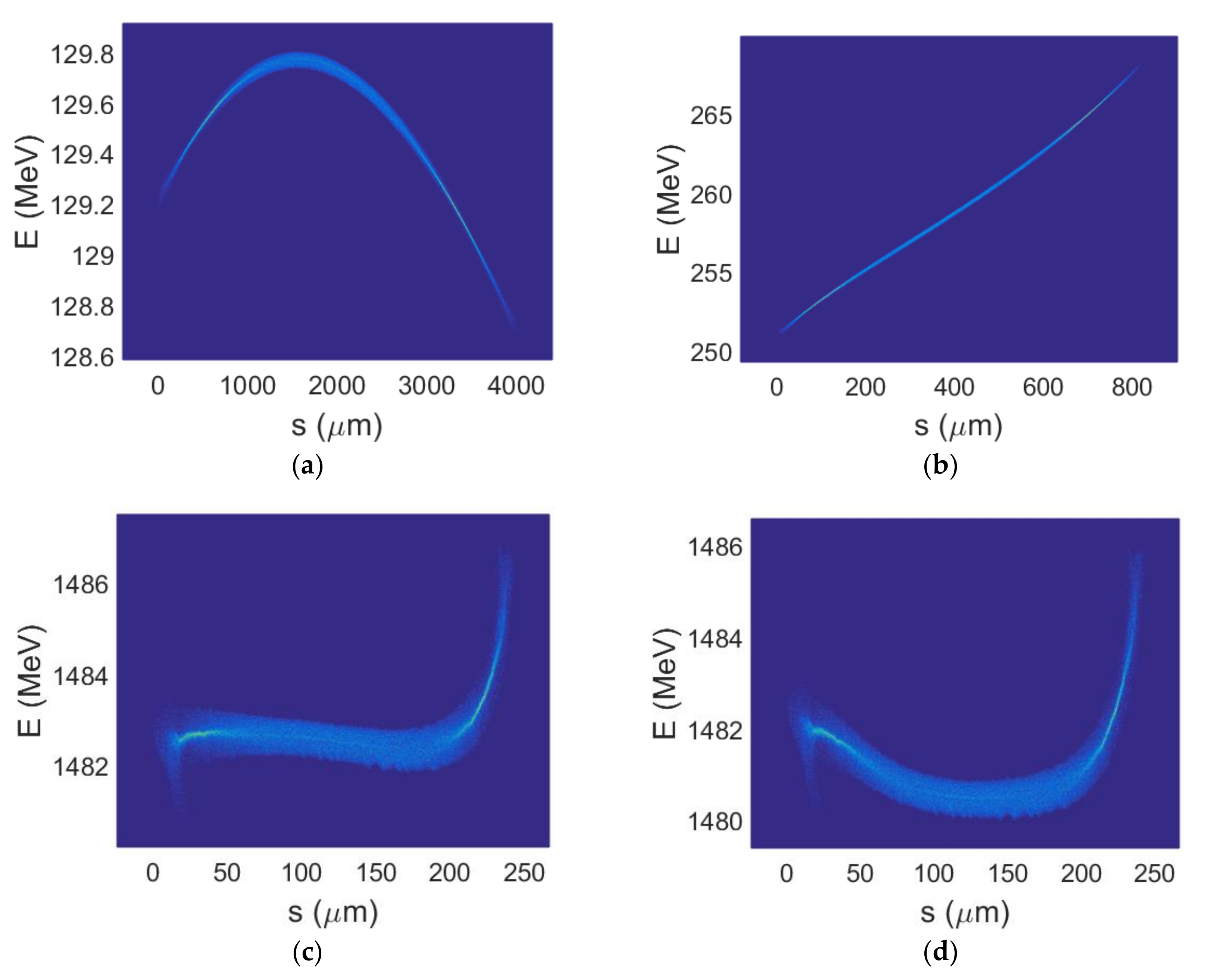
The 35-mm-aperture transport line delivers the beam to the switchyard section. The longitudinal wakefield of the accelerating structures and the resistive wall wakefield of the transport line lead to the “banana”-like longitudinal phase space of the electron beam. The phase space evolution of the electron beam, simulated by ELEGANT [36], are given in Figure 3. The designed parameters are listed in Table 2.
2.3. Switchyard
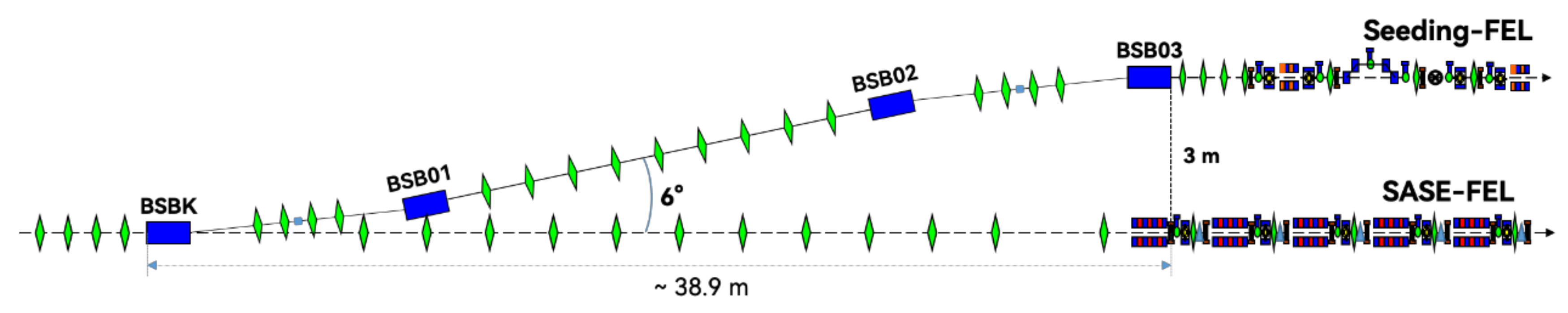
As is described above, there are two undulator lines with different FEL parameters and different operation modes available in SXFEL-UF. For feeding the two undulator lines with one linac, a beam switchyard is installed between the linac and the undulator section. A fast kicker which is programmable for bunch-by-bunch separation of the 50 Hz electron beam is used for directing the beam to the two undulator lines, respectively. When the kicker is off, the beam goes straightly to the SASE undulator line; while when the kicker is on, the beam is kicked horizontally and heads to the seeding undulator line through a dog-leg. A schematic of the switchyard is shown in Figure 4.
The switchyard should perform a beam deflection with the least perturbation as possible to the beam quality from the linac, particularly for the seeded FEL. To realize this, the beam switchyard line is designed to be a dual-DBA dog-leg structure, which consists of two symmetrical double-bend-achromat (DBA) and a matching section in between [37]. The kicker acts as the first bending magnet of the entrance DBA and the successive deflection is finished by three dipole magnets. The total deflection angle of the dog-leg is about 6° and the total length is about 39 m.
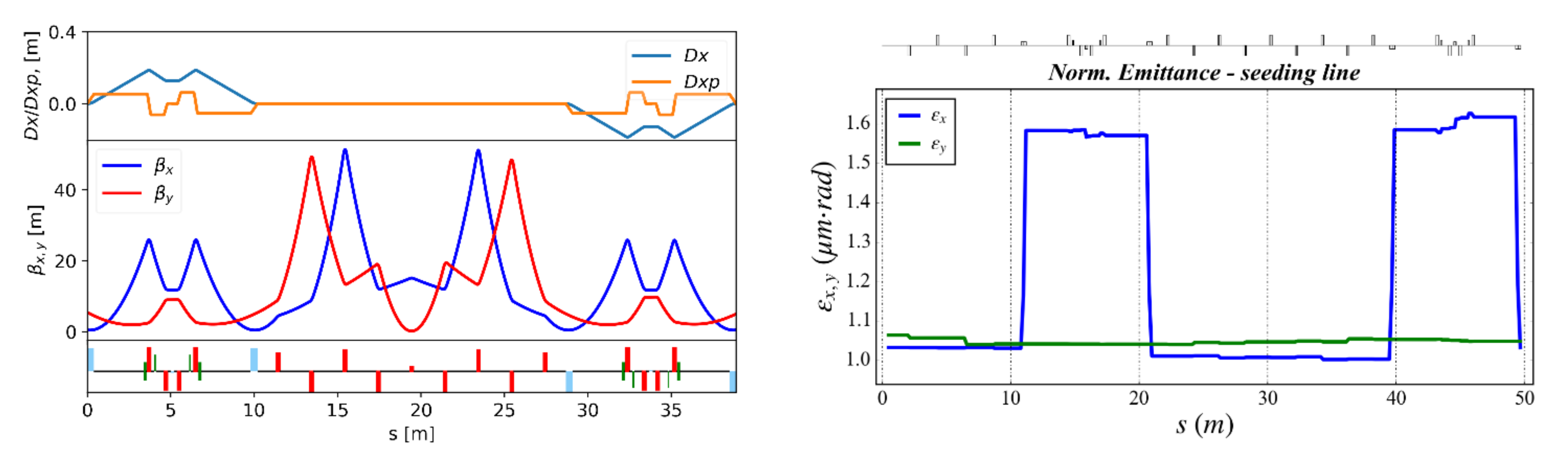
The optics of the beam switchyard are designed to be mirror symmetrical. For minimizing the CSR induced emittance growth, the beam size at the bending magnets is optimized to be very small for reducing the CSR kick. Meanwhile, the matching section between two DBAs is optimized to be a 𝜋 phase shifter for cancelling the CSR kick in the bending magnets, i.e., the “optics balance” method [38]. For suppressing the micro-bunching instability, a micro-bend is inserted in the middle of each DBA. A small reverse deflection angle to the DBA provides a compensation to the R56 of the DBA and thus a locally isochronous condition is realized. The lattice functions of the beam switchyard are shown in Figure 5 (left).
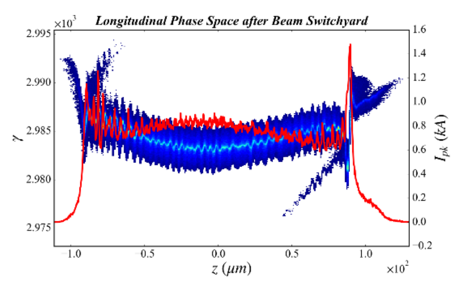
A start-to-end tracking from the linac end throughout the beam switchyard is performed by the code Elegant [36]. The results show a well-preserved beam quality along the switchyard section. With the designed optics, the emittance growth is less than 10%, shown in Figure 5 (right). Negligible longitudinal phase space distortion and microbunching growth are observed with the isochronous configuration, as shown in Figure 6.
2.4. Undulator Lines and the FEL Performance
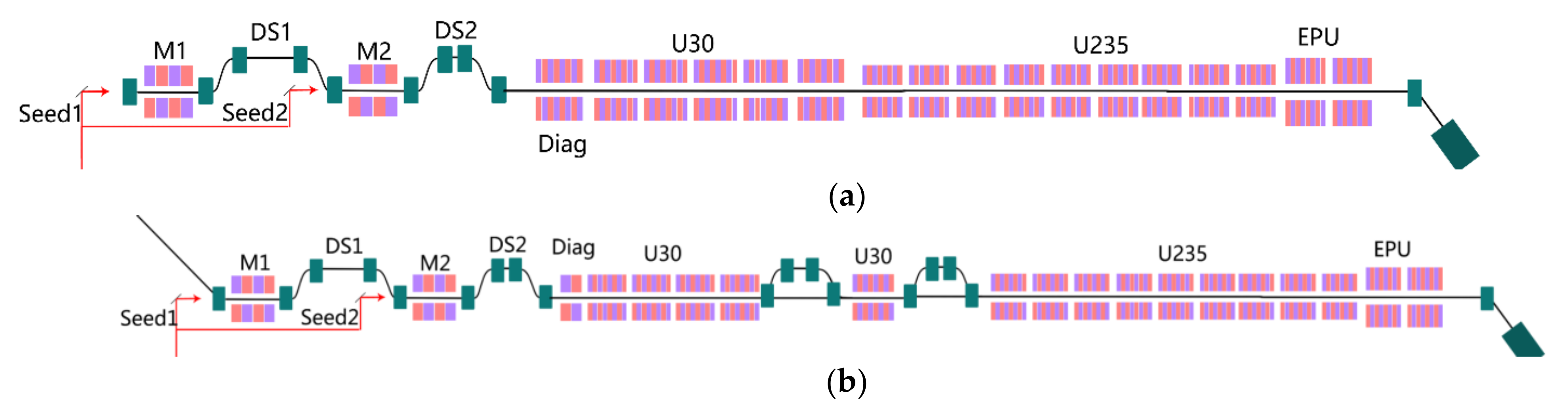
After the switchyard, the electron bunches are separately directed into two undulator lines: one is a newly built SASE line and the other is a seeding line upgraded from the test facility with some new undulator segments. The seeding line will be operated with either the single-stage EEHG [39] or EEHG-HGHG cascade scheme [10]. The layouts for these undulator lines with different setups are shown in Figure 7 and Figure 8.
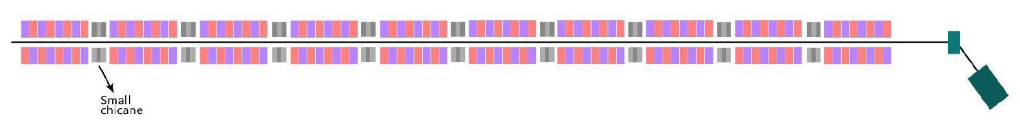
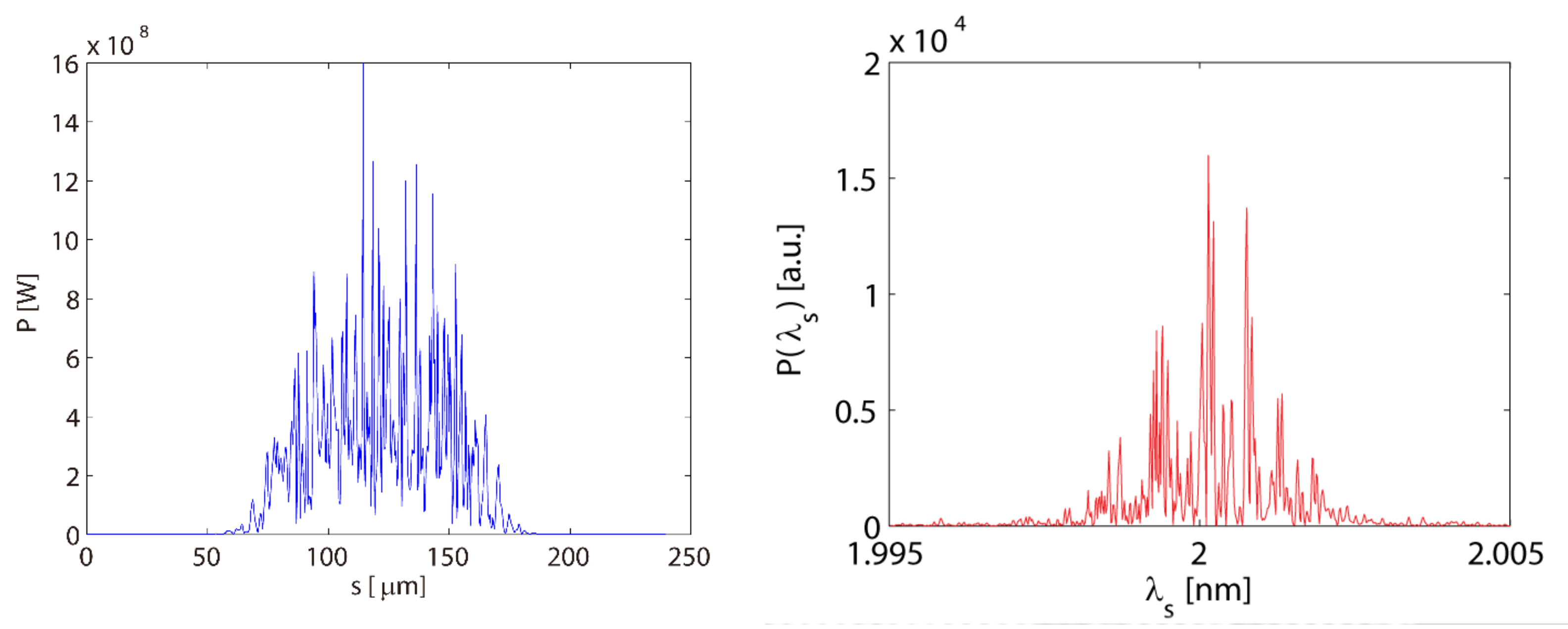
The SASE line consists of ten 16-mm-period in-vacuum undulators with minimum working gap as small as 3.7 mm and K of about 1.8. With a beam energy tuning from 0.8–1.35 GeV, the FEL radiation of this undulator line can easily cover the water window range. The shortest wavelength achievable is about 2 nm. Figure 9 shows the Genesis [40] simulation results of the SASE output at 2 nm, where the FEL saturation appears at around 40 m with the peak power of about 120 MW. The relative bandwidth (FWHM) of the SASE pulse at saturation is about 5 × 10⁻⁴. In Figure 7, one can also find small chicanes between the undulator segment, which are designed for advanced operation options, such as Optical Klystron [41,42], high-brightness SASE [43], fresh-slice [44,45], etc.
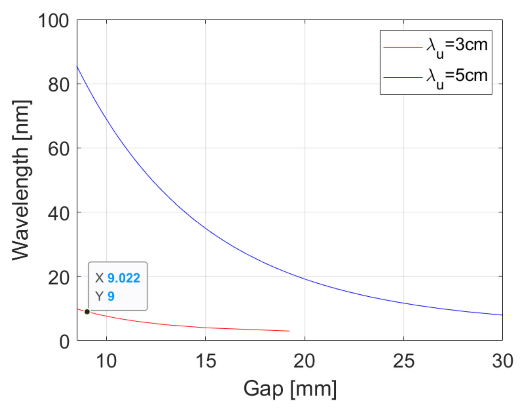
For the seeding undulator line, there are two basic operation modes: single stage EEHG and EEHG-HGHG cascade. Two 80-mm-period modulators with total length of 1.5 m are adopted for the energy modulations of EEHG. The long radiator consists of 18 undulators with four different types. The first undulator (diagnostic undulator) of the radiator is designed for the optimization of the EEHG at different harmonics. With two magnetic periods, 30 mm and 50 mm, that can be switched horizontally, this undulator can cover the wavelength from 3 nm to 66 nm, as shown in Figure 10, which is 4th–90th harmonics of the 266 nm seed laser, for a fixed beam energy. After the diagnostic undulator, there are five 30-mm-period undulators (U30) followed by 10 undulators with the period of 23.5 mm (U235), as shown in Figure 8a. By replacing the 6th and 8th undulators of the radiator with 3-m-long chicanes and the 7th undulator with a 30 mm-period undulator, the seeding line can also operate with the EEHG-HGHG cascade scheme. It is worth noting here that the U30s are designed for the FEL cascade operation modes. It is not used for generating FEL pulses for users since the source point of U30 will be moved significantly upstream with respect to that of U235.
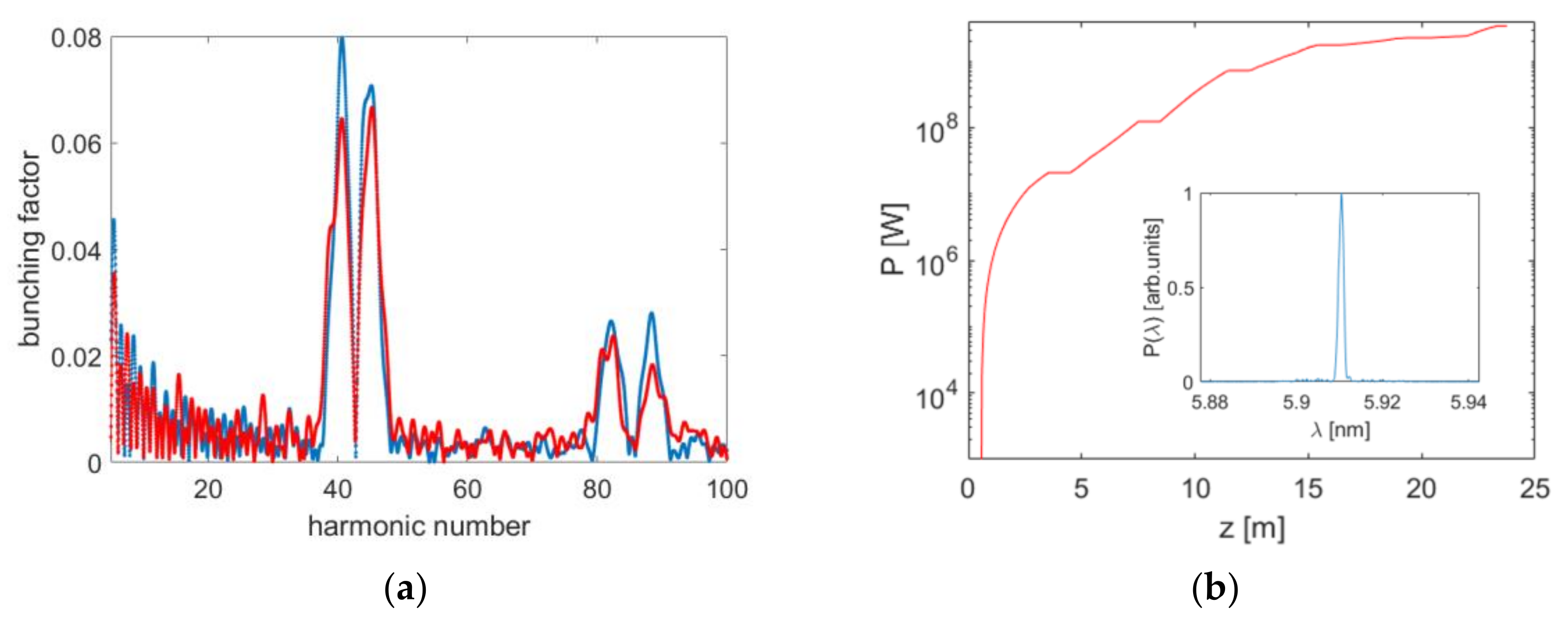
Figure 11 shows the simulation results for a single stage EEHG with the output wavelength at around 5.9 nm. The bunching factor of EEHG at about 5.9 nm is around 8%, which is large enough to initiate coherent radiation in the following radiator. The saturation length is about 15 m. The peak power of output is about 800 MW with the transform-limit bandwidth.
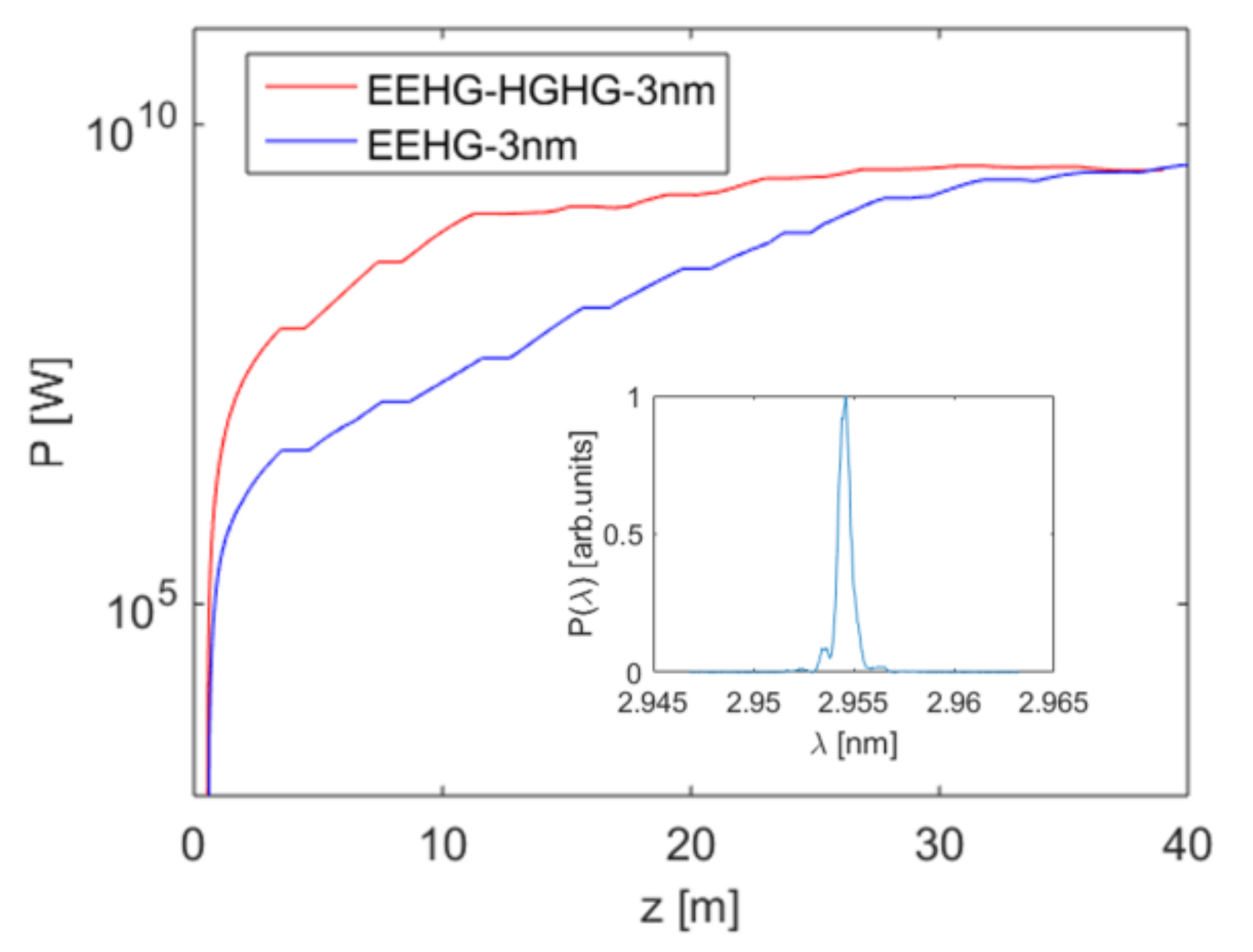
For the 3 nm radiation, with a harmonic number of 90, one can find in Figure 11a that the bunching factor is relatively small, of about only 3%. In addition, the bunching at the 90th harmonic is very sensitive to various machine parameters and 3D effects. As a result, the initial coherent radiation at 3 nm from a single-stage EEHG is relatively weak, as shown in Figure 12. The small initial bunching factor, together with the relatively large laser induced energy spread, result in a long saturation length of over 30 m for the single-stage EEHG. By using the EEHG-HGHG cascade with the first stage operated at 5.9 nm (45th harmonic) and the second stage operated at 3 nm (2nd harmonic), the bunching factor at about 3 nm in the second stage (HGHG) will be larger than 20% with a small laser induced slice energy spread, which helps to achieve higher peak power with very short undulator of only 10 m, as shown in Figure 12. In addition, the EEHG-HGHG cascade holds the possibility to achieve coherent radiation at even shorter wavelength.
3. Various Types of Undulators for SXFEL-UF
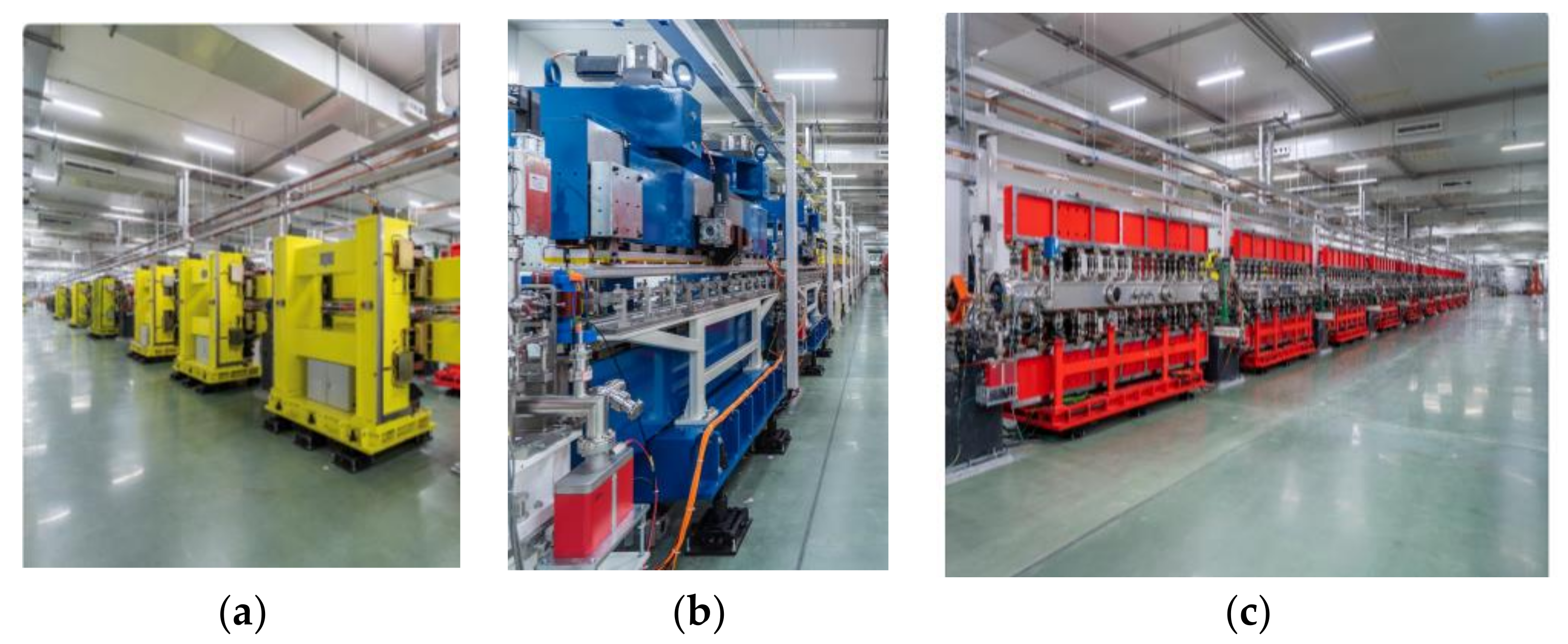
The SXFEL undulator parameters for seeding line and SASE line are listed in Table 3. Variable gap is realized with four independent servo motors for all the undulators. The challenges during fabrication include mass production, precise alignment, and synchronized motion. The SASE line mainly consists of ten in-vacuum undulators with 16 mm period, whereas the seeding line consists of ten U23.5 with period 23.5 mm, six U30 with period 30 mm and two elliptical polarization undulators EPU30, as shown in Figure 13. C-type mechanical frame has been adopted for all undulators. The motion control is based on Beckhoff PLC system and the gap measurement is achieved from absolute linear encoders. All electrical control boxes are fixed at the undulator support structure and therefore installed in the undulator tunnel. An IVU16 magnet assembly is mounted onto an extruded aluminum girder inside a two-side open-able vacuum chamber, thus magnetic performance of IVUs can be optimized with high precision hall probe even after the magnets have been put inside vacuum chamber. After magnetic field optimization at different gaps, the magnetic axis can be transferred to mechanical fiducial marks by a laser tracker system.
4. Commissioning Status
The civil construction of the SXFEL-UF undulator tunnel and experimental hall started in November 2016 and finished in 2018. The installation and commissioning of main components followed and continued until 2021.
4.1. Linac
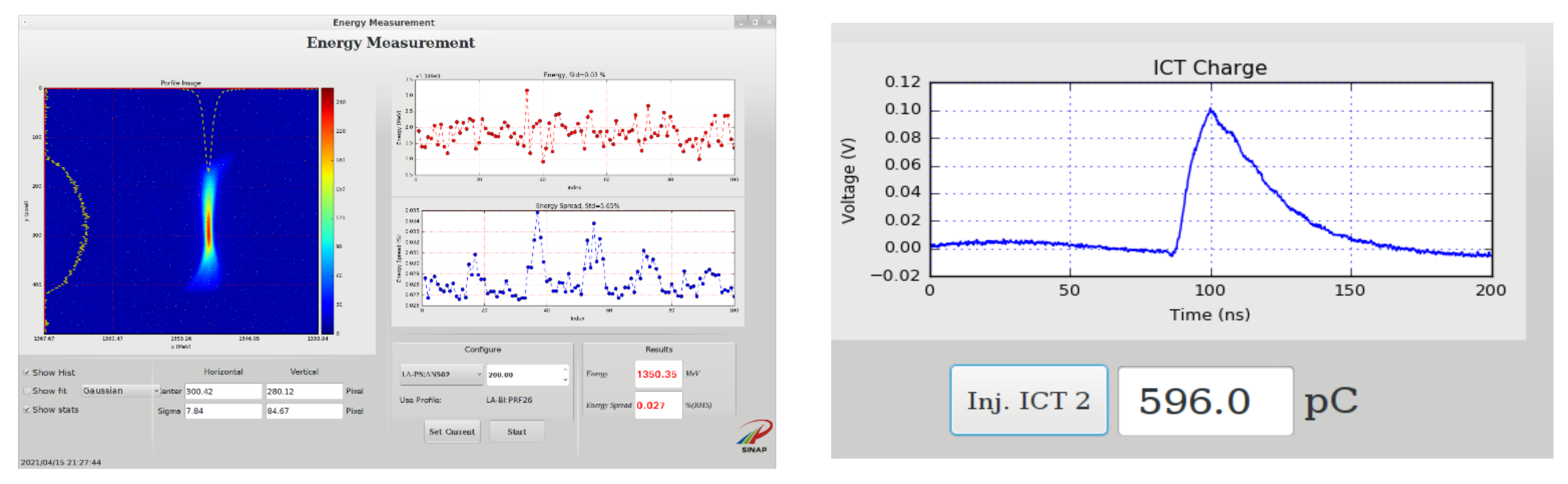
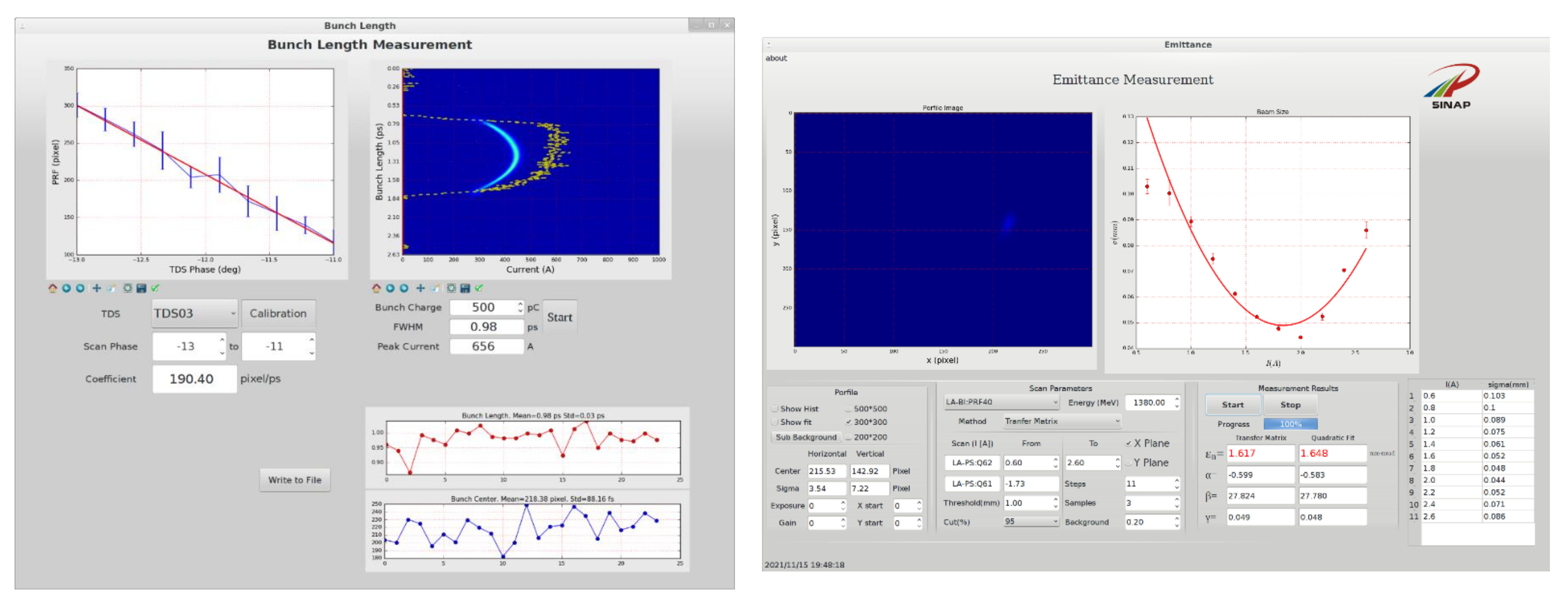
The linac commissioning finished in April 2021. The main commissioning results are summarized in Figure 14. The C-band deflecting cavity and the dipole magnet system is adopted to measure the longitudinal phase space of the beam. The beam energy is set to be 1.35 GeV with pulse duration of about 1 ps. The bunch charge is about 600 pC and the normalized project emittance (95%) is about 1.5 to 2.0 μm. Feedback systems, including the orbit feedback, bunch length feedback, drive laser feedback and energy feedback, are working well, ensuring the stability of the beam.
4.2. SASE FEL Line
The commissioning of the SASE FEL line started by the end of March 2021. Matching was performed first by using the quadrupoles upstream of the undulator. The first lasing of SASE at 5.6 nm was achieved at the end of April 2021. After that, saturations of SASE at 5.6 nm, 3.5 nm, 2.4 nm and 2.0 nm were achieved successively.
The radiation has been delivered to beamline and end-station since May 2021. After careful tuning and optimization, the FEL pulse energy reaches a few hundred micro-joules and the short-term stability can be better than 10%. The first set of test experiments have been performed at the coherent diffraction imaging end-station with 2.4 nm FEL radiation and the designed imaging resolution has been achieved.
4.3. Switchyard and Seeding FEL Line
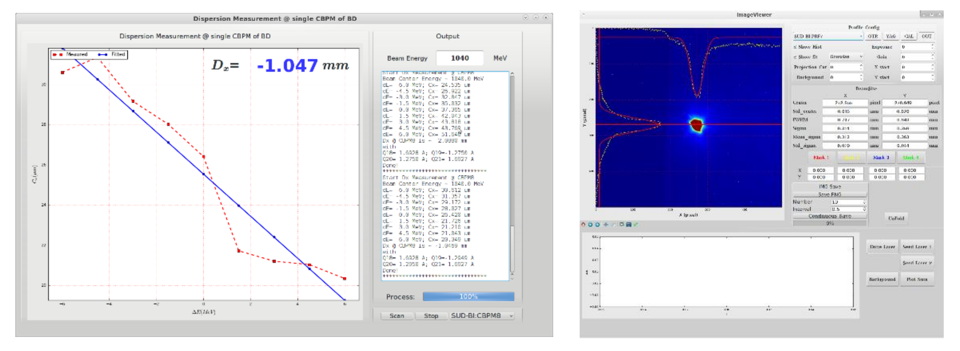
The commissioning of the Switchyard and Seeding FEL line just started at the beginning of November 2021. Some main commissioning results of the switchyard are shown in Figure 15. After passing through the switchyard, the electron beam quality had been well maintained. The residual dispersion after the switchyard is less than 2 mm with a slight optimization of the magnets in the two DBA cells around theoretical values. Transverse beam position jitter after the switchyard is less than 5% RMS relative to the beam size. With the optimized optics, only an acceptable emittance growth is observed after the switchyard compared with the exit of the linac. Beam matching had been applied to control the beam size in the undulator line. The first step for the commissioning of the seeding line starts from the tuning of SASE with the long radiator of EEHG. Recently, the lasing of SASE at 7.5 nm with the first six radiator undulators (U30) has been achieved.
5. Conclusions
The construction of the SXFEL-UF has been finished and the commissioning is in progress. With upgraded linac and a new SASE undulator line, stable soft X-ray pulses with pulse energy of several hundreds of micro-joules and photon energy covering the full water window range have been produced. The commissioning of the switchyard and the seeding line are still under way. The SXFEL-UF will open for users in 2022.
Author Contributions
Conceptualization and project administration of the SXFEL user facility, Z.Z., D.W., B.L., Q.G., G.F., L.Y., Y.L., M.G., Q.Z., C.F., D.G., H.D., M.Z., S.C., Z.W., F.G., S.S., W.Z. and W.F. All authors co-wrote the paper. All authors have read and agreed to the published version of the manuscript.
Funding
This work was supported by the National Key Research and Development Program of China (2018YFE0103100), the National Natural Science Foundation of China (11775294, 11905275, 11935020, 11975300, 12122514, 12125508) and the National Development and Reform Commission of China ([2016]1365).
Institutional Review Board Statement
Not applicable.
Informed Consent Statement
Not applicable.
Data Availability Statement
Data sharing is not applicable to this article.
Acknowledgments
The authors would like to thank the whole FEL team in SARI for their excellent work. Thanks also go to Senyu Chen, Li-Hua Yu, Zhi Liu, Huaidong Jiang, Zhirong Huang, Bart Faatz, Enrico Allaria, Luca Giannessi, Miltcho Danailov, Gennady Stupakov and Alexander Wu Chao for their help and support.
Conflicts of Interest
The authors declare no conflict of interest.
References
- Ackermann, W.A.; Asova, G.; Ayvazyan, V.; Azima, A.; Baboi, N.; Bähr, J.; Balandin, V.; Beutner, B.; Brandt, A.; Bolzmann, A.; et al. Operation of a free-electron laser from the extreme ultraviolet to the water window. Nat. Photonics 2007, 1, 336–342. [Google Scholar] [CrossRef]
- Emma, P.; Akre, R.; Arthur, J.; Bionta, R.; Bostedt, C.; Bozek, J.; Brachmann, A.; Bucksbaum, P.; Coffee, R.; Decker, F.-J.; et al. First lasing and operation of an ångstrom-wavelength free-electron laser. Nat. Photonics 2010, 4, 641–647. [Google Scholar] [CrossRef]
- Ishikawa, T.; Aoyagi, H.; Asaka, T.; Asano, Y.; Azumi, N.; Bizen, T.; Ego, H.; Fukami, K.; Fukui, T.; Furukawa, Y.; et al. A compact X-ray free-electron laser emitting in the sub-angstrom region. Nat. Photonics 2012, 6, 540–544. [Google Scholar] [CrossRef]
- Allaria, E.; Appio, R.; Badano, L.; Barletta, W.A.; Bassanese, S.; Biedron, S.G.; Borga, A.; Busetto, E.; Castronovo, D.; Cinquegrana, P.; et al. Highly coherent and stable pulses from the FERMI seeded free-electron laser in the extreme ultraviolet. Nat. Photonics 2012, 6, 699–704. [Google Scholar] [CrossRef]
- Kang, H.S.; Min, C.K.; Heo, H.; Kim, C.; Yang, H.; Kim, G.; Nam, I.; Baek, S.Y.; Choi, H.J.; Mun, G.; et al. Hard X-ray free-electron laser with femtosecond-scale timing jitter. Nat. Photonics 2017, 11, 708–713. [Google Scholar] [CrossRef]
- Prat, E.; Abela, R.; Aiba, M.; Alarcon, A.; Alex, J.; Arbelo, Y.; Arrell, C.; Arsov, V.; Bacellar, C.; Beard, C.; et al. A compact and cost-effective hard X-ray free-electron laser driven by a high-brightness and low-energy electron beam. Nat. Photonics 2020, 14, 748–754. [Google Scholar] [CrossRef]
- Decking, W.; Abeghyan, S.; Abramian, P.; Abramsky, A.; Aguirre, A.; Albrecht, C.; Alou, P.; Altarelli, M.; Altmann, P.; Amyan, K.; et al. A MHz-repetition-rate hard X-ray free-electron laser driven by a superconducting linear accelerator. Nat. Photonics 2020, 14, 391–397. [Google Scholar] [CrossRef]
- Zhao, Z.T.; Chen, S.Y.; Yu, L.H.; Tang, C.X.; Yin, L.X.; Wang, D.; Gu, Q. Shanghai soft X-ray free electron laser test facility. In Proceedings of the IPAC2011, San Sebastián, Spain, 4–9 September 2011; pp. 3011–3013. [Google Scholar]
- Zhao, Z.T.; Wang, D.; Yin, L.X.; Gu, Q.; Fang, G.P.; Liu, B. The current status of the SXFEL project. AAPPS Bull. 2016, 26, 12–24. [Google Scholar]
- Zhao, Z.; Wang, D.; Gu, Q.; Yin, L.; Gu, M.; Leng, Y.; Liu, B. Status of the SXFEL Facility. Appl. Sci. 2017, 7, 607. [Google Scholar] [CrossRef] [Green Version]
- SLAC National Accelerator Laboratory. Linac Coherent Light Source II (LCLS-II) Project Final Design Report—LCLSII-1.1-dr-0251-r0; SLAC National Accelerator Laboratory: Menlo Park, CA, USA, 2015. [Google Scholar]
- Liu, T.; Dong, X.; Feng, C. Start-to-end Simulations of the Reflection Hard X-Ray Self-Seeding at the SHINE Project. In Proceedings of the 39th International Free Electron Laser Conference—FEL 19, Hamburg, Germany, 26–30 August 2019; pp. 254–257. [Google Scholar] [CrossRef]
- Kondratenko, A.M.; Saldin, E.L. Generating of coherent radiation by a relativistic electron beam in an ondulator. Part. Accel. 1980, 10, 207–216. [Google Scholar]
- Bonifacio, R.; Pellegrini, C.; Narducci, L.M. Collective instabilities and high-gain regime in a free electron laser. Opt. Commun. 1984, 50, 373–378. [Google Scholar] [CrossRef] [Green Version]
- Yu, L.-H. Generation of intense uv radiation by subharmonically seeded single-pass free-electron lasers. Phys. Rev. A 1991, 44, 5178. [Google Scholar] [CrossRef]
- Yu, L.-H.; Babzien, M. High-gain harmonic-generation free-electron laser. Science 2000, 289, 932–935. [Google Scholar] [CrossRef] [Green Version]
- Stupakov, G. Using the Beam-Echo Effect for Generation of Short-Wavelength Radiation. Phys. Rev. Lett. 2009, 102, 074801. [Google Scholar] [CrossRef] [Green Version]
- Xiang, D.; Stupakov, G. Echo-enabled harmonic generation free electron laser. Phys. Rev. ST Accel. Beams 2009, 12, 030702. [Google Scholar] [CrossRef] [Green Version]
- Yu, L.-H.; Ben-Zvi, I. High-gain harmonic generation of soft X-rays with the “fresh bunch” technique. Nucl. Instrum. Methods Phys. Res. Sect. A Accel. Spectrometers Detect. Assoc. Equip. 1997, 393, 96–99. [Google Scholar] [CrossRef] [Green Version]
- Wu, J.H.; Yu, L.H. Coherent Hard X-ray Production by Cascading Stages of High Gain Harmonic Generation X-ray FEL. Nucl. Instrum. Methods A 2001, 475, 104–111. [Google Scholar] [CrossRef]
- Xiang, D.; Colby, E.; Dunning, M.; Gilevich, S.; Hast, C.; Jobe, K.; McCormick, D.; Nelson, J.; Raubenheimer, T.O.; Soong, K.; et al. Demonstration of the echo-enabled harmonic generation technique for short-wavelength seeded free electron lasers. Phys. Rev. Lett. 2010, 105, 14801. [Google Scholar] [CrossRef] [Green Version]
- Xiang, D.; Colby, E.; Dunning, M.; Gilevich, S.; Hast, C.; Jobe, K.; McCormick, D.; Nelson, J.; Raubenheimer, T.O.; Soong, K.; et al. Evidence of high harmonics from echo-enabled harmonic generation for seeding X-ray free electron lasers. Phys. Rev. Lett. 2012, 108, 024802. [Google Scholar] [CrossRef] [Green Version]
- Hemsing, E.; Dunning, M.; Hast, C.; Raubenheimer, T.O.; Weathersby, S.; Xiang, D. Highly coherent vacuum ultraviolet radiation at the 15th harmonic with echo-enabled harmonic generation technique. Phys. Rev. ST Accel. Beams 2014, 17, 070702. [Google Scholar] [CrossRef] [Green Version]
- Hemsing, E.; Dunning, M.; Garcia, B.; Hast, C.; Raubenheimer, T.; Stupakov, G.; Xiang, D. Echo-enabled harmonics up to the 75th order from precisely tailored electron beams. Nat. Photonics 2016, 10, 512–515. [Google Scholar] [CrossRef]
- Zhao, Z.T.; Wang, D.; Chen, J.H.; Chen, Z.H.; Deng, H.X.; Ding, J.G.; Feng, C.; Gu, Q.; Huang, M.M.; Lan, T.H.; et al. First lasing of an echo-enabled harmonic generation free-electron laser. Nat. Photonics 2012, 6, 360–363. [Google Scholar] [CrossRef]
- Liu, B.; Li, W.B.; Chen, J.H.; Chen, Z.H.; Deng, H.X.; Ding, J.G.; Fan, Y.; Fang, G.P.; Feng, C.; Feng, L.; et al. Demonstration of a widely-tunable and fully-coherent high-gain harmonic-generation free-electron laser. Phys. Rev. Spec. Top. Accel. Beams 2013, 16, 020704. [Google Scholar] [CrossRef]
- Allaria, E.; Castronovo, D.; Cinquegrana, P.; Craievich, P.; Dal Forno, M.; Danailov, M.B.; D’Auria, G.; Demidovich, A.; De Ninno, G.; Di Mitri, S.; et al. Two-stage seeded soft-X-ray free-electron laser. Nat. Photonics 2013, 7, 913–918. [Google Scholar] [CrossRef]
- Ribič, P.R.; Abrami, A.; Badano, L.; Bossi, M.; Braun, H.H.; Bruchon, N.; Capotondi, F.; Castronovo, D.; Cautero, M.; Cinquegrana, P. Coherent soft X-ray pulses from an echo-enabled harmonic generation free-electron laser. Nat. Photonics 2019, 13, 555–561. [Google Scholar] [CrossRef] [Green Version]
- Feng, C.; Deng, H.; Zhang, M.; Wang, X.; Chen, S.; Liu, T.; Zhou, K.; Gu, D.; Wang, Z.; Jiang, Z.; et al. Coherent extreme ultraviolet free-electron laser with echo-enabled harmonic generation. Phys. Rev. Accel. Beams 2019, 22, 050703. [Google Scholar] [CrossRef] [Green Version]
- Miao, J.; Sandberg, R.L.; Song, C. Coherent X-ray diffraction imaging. IEEE J. Sel. Top. Quantum Electron. 2011, 18, 399–410. [Google Scholar] [CrossRef]
- Bostedt, C.; Bozek, J.; Bucksbaum, P.; Coffee, R.; Hastings, J.; Huang, Z.; Lee, R.; Schorb, S.; Corlett, J.; Denes, P. Ultra-fast and ultra-intense x-ray sciences: First results from the Linac Coherent Light Source free-electron laser. J. Phys. B At. Mol. Opt. Phys. 2013, 46, 164003. [Google Scholar] [CrossRef]
- Feldhaus, J.; Krikunova, M.; Meyer, M.; Möller, T.; Moshammer, R.; Rudenko, A.; Tschentscher, T.; Ullrich, J. AMO science at the FLASH and European XFEL free-electron laser facilities. J. Phys. B At. Mol. Opt. Phys. 2013, 46, 164002. [Google Scholar] [CrossRef]
- Lu, W.; Friedrich, B.; Noll, T.; Zhou, K.; Hallmann, J.; Ansaldi, G.; Roth, T.; Serkez, S.; Geloni, G.; Madsen, A. Development of a hard X-ray split-and-delay line and performance simulations for two-color pump-probe experiments at the European XFEL. Rev. Sci. Instrum. 2018, 89, 063121. [Google Scholar] [CrossRef]
- Huang, Z.; Borland, M.; Emma, P.; Wu, J.; Limborg, C.; Stupakov, G.; Welch, J. Suppression of microbunching instability in the linac coherent light source. Phys. Rev. Spec. Top.-Accel. Beams 2004, 7, 074401. [Google Scholar] [CrossRef] [Green Version]
- Sun, Y.; Emma, P.; Raubenheimer, T.; Wu, J. X-band rf driven free electron laser driver with optics linearization. Phys. Rev. Spec. Top.-Accel. Beams 2014, 17, 110703. [Google Scholar] [CrossRef] [Green Version]
- Borland, M. Elegant: A Flexible SDDS-Compliant Code for Accelerator Simulation; Technical Report No. LS-287; Advanced Photon Source: Argonne, IL, USA, 2000. [Google Scholar]
- Chen, S.; Deng, H.; Feng, C.; Wang, R.; Liu, B.; Wang, D. Design of the Beam Switchyard of a Soft X-ray FEL User Facility in Shanghai. In Proceedings of the IPAC2018, Vancouver, BC, Canada, 29 April–4 May 2018; pp. 4456–4459. [Google Scholar] [CrossRef]
- Di Mitri, S.; Cornacchia, M.; Spampinati, S. Cancellation of coherent synchrotron radiation kicks with optics balance. Phys. Rev. Lett. 2013, 110, 014801. [Google Scholar] [CrossRef]
- Feng, C.; Huang, D.; Deng, H.; Chen, J.; Xiang, D.; Liu, B.; Wang, D.; Zhao, Z. A single stage EEHG at SXFEL for narrow-bandwidth soft X-ray generation. Sci. Bull. 2016, 61, 1202–1212. [Google Scholar] [CrossRef] [Green Version]
- Reiche, S. GENESIS 1.3: A fully 3D time-dependent FEL simulation code. Nucl. Instrum. Methods A 1999, 429, 243–248. [Google Scholar] [CrossRef]
- Ding, Y.; Emma, P.; Huang, Z.; Kumar, V. Optical klystron enhancement to self-amplified spontaneous emission free electron lasers. Phys. Rev. Spec. Top.-Accel. Beams 2006, 9, 070702. [Google Scholar] [CrossRef] [Green Version]
- Penco, G.; Allaria, E.; De Ninno, G.; Ferrari, E.; Giannessi, L. Experimental demonstration of enhanced self-amplified spontaneous emission by an optical klystron. Phys. Rev. Rev. Lett. 2015, 114, 013901. [Google Scholar] [CrossRef] [Green Version]
- Thompson, N.; McNeil, B.; Dunning, D. High brightness SASE operation of X-ray FELs. Phys. Procedia 2014, 52, 52–61. [Google Scholar] [CrossRef] [Green Version]
- Lutman, A.A.; Guetg, M.W.; Maxwell, T.J.; MacArthur, J.P.; Ding, Y.; Emma, C.; Krzywinski, J.; Marinelli, A.; Huang, Z. High-power femtosecond soft x rays from fresh-slice multistage free-electron lasers. Phys. Rev. Lett. 2018, 120, 264801. [Google Scholar] [CrossRef] [Green Version]
- Lutman, A.A.; Maxwell, T.J.; MacArthur, J.P.; Guetg, M.W.; Berrah, N.; Coffee, R.N.; Ding, Y.; Huang, Z.; Marinelli, A.; Moeller, S. Fresh-slice multicolour X-ray free-electron lasers. Nat. Photonics 2016, 10, 745–750. [Google Scholar] [CrossRef]
Figure 1.
Schematic layouts of the SXFEL: from test facility (upper) to user facility (lower).

Figure 2.
Schematic layout of the main linac of the SXFEL-UF.

Figure 3.
Longitudinal phase space evolution of the electron beam at the exit of the (a) injector, (b) BC1, (c) main linac, and (d) transport line.
Figure 3.
Longitudinal phase space evolution of the electron beam at the exit of the (a) injector, (b) BC1, (c) main linac, and (d) transport line.

Figure 4.
Schematic layout of the beam switchyard of SXFEL-UF.

Figure 5.
Lattice functions (left) and emittance evolution (right) of the beam switchyard.

Figure 6.
Beam longitudinal phase space at the end of the beam switchyard.

Figure 7.
Schematic layout of the SASE line.

Figure 8.
Schematic layouts of the seeding line with different setups: (a) single-stage EEHG; (b) EEHG-HGHG cascade.
Figure 8.
Schematic layouts of the seeding line with different setups: (a) single-stage EEHG; (b) EEHG-HGHG cascade.

Figure 9.
Simulation results for SASE at 2 nm: radiation pulse (left) and single-shot spectrum (right) at saturation.
Figure 9.
Simulation results for SASE at 2 nm: radiation pulse (left) and single-shot spectrum (right) at saturation.

Figure 10.
The wavelength coverage of the diagnostic undulator with different periods for a fix beam energy of 1.35 GeV.
Figure 10.
The wavelength coverage of the diagnostic undulator with different periods for a fix beam energy of 1.35 GeV.

Figure 11.
Simulation results of the single stage EEHG at 5.9 nm: (a) bunching factor distribution for various harmonics; (b) gain curve and the single-shot spectrum at saturation.
Figure 11.
Simulation results of the single stage EEHG at 5.9 nm: (a) bunching factor distribution for various harmonics; (b) gain curve and the single-shot spectrum at saturation.

Figure 12.
Comparison between a single-stage EEHG and EEHG-HGHG cascade with the wavelength of about 3 nm.
Figure 12.
Comparison between a single-stage EEHG and EEHG-HGHG cascade with the wavelength of about 3 nm.

Figure 13.
SXFEL undulators in tunnel: (a) yellow color U23.5 and U30; (b) blue color EPU; (c) red color IVU16.
Figure 13.
SXFEL undulators in tunnel: (a) yellow color U23.5 and U30; (b) blue color EPU; (c) red color IVU16.

Figure 14.
Main commissioning results of the linac after upgrade.


Figure 15.
Main commissioning results of the beam switchyard.


Table 1.
Main parameters of the SXFEL-UF.
| Parameter | Values | Unit |
|---|---|---|
| linac | ||
| Electron energy | 1.5 | GeV |
| Project energy spread (rms) | ≤0.1 | % |
| Normalized project emittance (rms) | ≤1.5 | mm·mrad |
| Bunch charge | 0.5 | nC |
| Peak current | ≥700 | A |
| Undulator | ||
| SASE line | ||
| Central wavelength | ~2 | nm |
| Output peak power | ≥100 | MW |
| Seeding line | ||
| Central wavelength | ~3 | nm |
| Output peak power | ≥100 | MW |
Table 2.
Designed parameters of the linac.
| Section | Energy (MeV) | Pulse Duration (ps, FWHM) | Gradient (MV/m) | RF Phase/Bend Angle (deg) | R56 (mm) |
|---|---|---|---|---|---|
| L1 | 250 | 10 | 20 | −30.5 | - |
| X | 235 | 10 | 16 | 180 | - |
| BC1 | - | 0.8 | 3.968 | −48 | |
| L2 | 640 | 0.8 | 38 | 5 | - |
| BC2 | - | 0.8 | 0 | 0 | |
| L3 | 1500 | 0.8 | 38 | 5 | - |
Table 3.
Parameters of SXFEL undulators.
| SASE | Seeding | ||||
|---|---|---|---|---|---|
| Model | IVU16 | EPU20 | U23.5 | U30/50 | EPU30 |
| Period Length (mm) | 16 | 20 | 23.5 | 30/50 | 30 |
| Min. gap (mm) | 3.8 | 6.7 | 8.75 | 9 | 9.3 |
| Effective field (T) | 1.14 | 0.8 | 0.65 | 0.8/1.18 | 0.8 |
| Magnet | SmCo Br = 1.13 T | NdFeB Br = 1.3 T | NdFeB Br = 1.25 T | NdFeB Br = 1.25 T | NdFeB Br = 1.25 T |
| Magnet Structure | IVU-Hybrid | APPLE-III | Hybrid | Hybrid: switchable | APPLE-II |
Publisher’s Note: MDPI stays neutral with regard to jurisdictional claims in published maps and institutional affiliations. |
© 2021 by the authors. Licensee MDPI, Basel, Switzerland. This article is an open access article distributed under the terms and conditions of the Creative Commons Attribution (CC BY) license (https://creativecommons.org/licenses/by/4.0/).
Share and Cite
MDPI and ACS Style
Liu, B.; Feng, C.; Gu, D.; Gao, F.; Deng, H.; Zhang, M.; Sun, S.; Chen, S.; Zhang, W.; Fang, W.; et al. The SXFEL Upgrade: From Test Facility to User Facility. Appl. Sci. 2022, 12, 176. https://0-doi-org.brum.beds.ac.uk/10.3390/app12010176
AMA Style
Liu B, Feng C, Gu D, Gao F, Deng H, Zhang M, Sun S, Chen S, Zhang W, Fang W, et al. The SXFEL Upgrade: From Test Facility to User Facility. Applied Sciences. 2022; 12(1):176. https://0-doi-org.brum.beds.ac.uk/10.3390/app12010176
Chicago/Turabian StyleLiu, Bo, Chao Feng, Duan Gu, Fei Gao, Haixiao Deng, Meng Zhang, Sen Sun, Si Chen, Wei Zhang, Wencheng Fang, and et al. 2022. "The SXFEL Upgrade: From Test Facility to User Facility" Applied Sciences 12, no. 1: 176. https://0-doi-org.brum.beds.ac.uk/10.3390/app12010176
Note that from the first issue of 2016, this journal uses article numbers instead of page numbers. See further details here.