
Recent Progress of the PAL-XFEL
by
 , , , , , ,
Intae Eom
1,2,* ,
,
Sae Hwan Chun
1,2,
Jae Hyuk Lee
1,2,
Daewoong Nam
1,2,
Rory Ma
1,2,
Jaehyun Park
1,3,
Sehan Park
1,
Sang Han Park
1,
Haeryong Yang
1,
Inhyuk Nam
1,
Myung Hoon Cho
1,
Chi Hyun Shim
1,
Gyujin Kim
1,
Chang-Ki Min
1,
Hoon Heo
1,
Heung-Sik Kang
1 and
Changbum Kim
1,* 1
Pohang Accelerator Laboratory, Pohang 37673, Korea
2
Photon Science Center, POSTECH, Pohang 37673, Korea
3
Department of Chemical Engineering, POSTECH, Pohang 37673, Korea
*
Authors to whom correspondence should be addressed.
Appl. Sci. 2022, 12(3), 1010; https://0-doi-org.brum.beds.ac.uk/10.3390/app12031010
Submission received: 23 December 2021
/
Revised: 15 January 2022
/
Accepted: 15 January 2022
/
Published: 19 January 2022
(This article belongs to the Special Issue Latest Trends in Free Electron Lasers)
Abstract
:The X-ray free-electron laser of the Pohang Accelerator Laboratory (PAL-XFEL) was opened to users in 2017. Since then, significant progress has been made in PAL-XFEL operation and beamline experiments. This includes increasing the FEL pulse energy, increasing the FEL photon energy, generating self-seeding FEL, and trials of two-color operation. In the beamline, new instruments or endstations have been added or are being prepared. Overall, beamline operation has been stabilized since its initiation, which has enabled excellent scientific results through efficient user experiments. In this paper, we describe details of the recent progress of the PAL-XFEL.
1. Introduction
One of the most important developments in the light source community in the last two decades was the X-ray free-electron laser (XFEL). The Linac Coherent Light Source (LCLS) at the SLAC National Accelerator Laboratory was constructed in 2009 as the first XFEL in the world using the existing normal conducting linear accelerator (Linac) [1] and opening a new era of the XFEL. Following the large success of the LCLS, XFELs became a megatrend, and a series of XFELs were constructed around the world. In Japan, the SPring-8 angstrom compact free-electron laser (SACLA) was constructed in 2011 using a thermionic electron gun and in-vacuum undulators [2]. The XFEL of the Pohang Accelerator Laboratory (PAL-XFEL) was opened to users in June 2017 [3]. The European XFEL, the biggest XFEL in the world, was opened to users in September 2017 at the Deutsches Elektronen Synchrotron (DESY) [4]. Most recently, the Swiss FEL of the Paul Scherrer Institut (PSI) started official user service in 2019 [5].
This substantial interest is due to the fact that the FEL can generate coherent radiation with an extreme intensity. When an electron beam passes through a long undulator, the periodic modulation of charge density can happen inside the electron beam from the interaction between the electron beam and the synchrotron radiation emitted from the upstream undulator. This is called micro-bunching of the electron beam, and the separation of micro-bunches is equal to the wavelength of the emitted undulator radiation. These micro-bunches radiate coherent radiation, and the radiation intensity can be increased exponentially up to saturation. This process is called the self-amplification of spontaneous emission (SASE). The SASE FEL is transversely coherent and diffraction-limited in both planes when a sufficiently long undulator is used due to the gain-guiding [6]. This means that only a single diffraction-limited radiation mode is amplified to saturation in the FEL process; however, starting from the initial shot noise of the electron beam, SASE FEL radiation shows a chaotic behavior from the stochastic nature of spontaneous radiation and exhibits inherent spectral and intensity instability. Self-seeding FEL was proposed to solve the problem by introducing a coherent light pulse that produces micro-bunching in the electron beam in an internal way [7]. In particular, self-seeding FEL showed that the spectral bandwidth can be reduced by more than an order of magnitude close to the transform-limited case [8].
Since being opened to users, significant progress has been made at the PAL-XFEL. In terms of the accelerator, the FEL pulse energy has been continuously increased to more than 1.2 mJ in all photon energy ranges. The FEL photon energy was doubled from 12 keV to 20 keV for various experiments in the beamline. To improve the temporal coherency of the SASE FEL, self-seeding was evaluated from the very beginning, and the brightest FEL in the world was achieved at the end of 2020. To explore the new era of the X-ray pump-probe experiment, two-color FEL was implemented, showing promising results. In this paper, we present the features of the PAL-XFEL and describe the recent progress of the PAL-XFEL in detail.
2. Overview of PAL-XFEL
2.1. Accelerator
In 2017, the PAL-XFEL started providing a 0.1 nm wavelength XFEL for user experiments. The electron beam of 150 pC charge was generated from a photocathode RF gun with an ultraviolet (UV) laser pulse of 2–3 ps pulse width. The generated electron beam was accelerated to 10 GeV energy using S-band (2856 MHz) RF structures in the 780 m long linac. During acceleration, the electron bunch length was reduced to 20–30 fs in full width at half maximum (FWHM) after three bunch compressors and a 3 kA peak current was obtained at the linac end. The electron beam came into the undulator section after passing through a beam transport line and generated a hard X-ray pulse using the SASE process. Table 1 shows the operational parameters of the PAL-XFEL.
Since the PAL-XFEL was opened to the public, beamtime for user service has been increased every year to provide more opportunities for user experiments. In 2020, 3012 h were provided for user beamtime with a beam availability of 96.9%. The provided beamtime of 3012 h was significantly increased from 1440 h in 2017, as shown in Table 2. To further increase beamtime, PAL-XFEL has plans for 24 h operation and simultaneous operation of the hard and soft X-ray beamline in the near future.
2.2. Beamlines
PAL-XFEL has successfully supported more than 200 user experiments as of 2021, since user operation began in June 2017. It has been continuously improved to provide extended experimental techniques and sample environments, and more than 10 endstations are currently operating for hard and soft X-ray experiments. The highest level of timing stability, 20 fs (root mean square, RMS) jitter between XFEL and the optical laser [3], ensures an experimental time resolution of 80 fs (FWHM) without jitter correction in typical diffraction measurements using an 800 nm, 40 fs pump. The X-ray photon flux in the beamlines is ≥1011 photons/pulse for hard X-rays and ≥1012 photons/pulse for soft X-rays. The excellent beam quality of the PAL-XFEL has been unveiled with respect to many ultrafast phenomena such as structural dynamics [9], chemical reaction dynamics [10,11,12], phase transition [13,14,15,16], spin, charge, and magnetic dynamics [9,17,18,19].
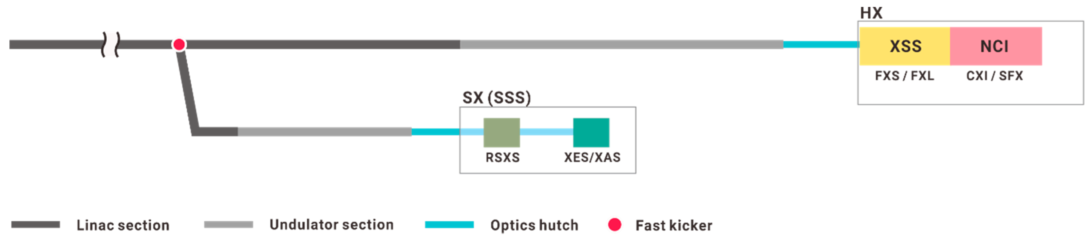
Figure 1 shows a schematic view of the PAL-XFEL beamlines, and the experimental techniques provided by each beamline/hutch and endstation are listed in Table 3. Two experimental hutches in the hard X-ray hall and two endstations in the soft X-ray hall are placed in tandem and share each FEL line. Accordingly, one user experiment can be conducted at once. Usually, the beamtime is supported on a shift basis, 12 h a day, and the beamtime can be exchanged day and night between HX and SX, or it can be supported continuously for 24 h for some experiments. Currently, a 60 Hz kicker at the branching point for the SX is under preparation. Therefore, the simultaneous operation of two FEL lines will be available shortly.
The X-ray scattering and spectroscopy (XSS) beamline [20] aims to provide all fundamental time-resolved X-ray experiments, including scattering, diffraction, and spectroscopies. Currently, we support X-ray diffraction experiments on bulk or thin-film samples, as well as wide-angle X-ray scattering (WAXS) and X-ray absorption spectroscopy (XAS) on liquid-phase samples. New spectrometers for X-ray emission spectroscopy and resonant inelastic X-ray scattering (RIXS) measurements will be introduced in 2022. In the XSS, the X-ray can be focused by a stack of Be compound refractive lenses (CRL), and the typical focus size at the sample position is about 10 μm (FWHM) at 9.7 keV. Standard configurations utilize hexapod-based two-circle or four-circle diffractometers with an optical pump laser which has an incidence angle of about 10° in a horizontal or vertical direction. For the low-temperature experiments, cryostream (40–300 K) or displex (10–450 K) cryostats can be used together with diffractometers. Thanks to a platform on the hexapod and an auxiliary optical table combined with the four-circle diffractometer, we can flexibly modify the experimental setup around the sample position, or a user can integrate their own chamber.
The nanocrystallography and coherent imaging (NCI) beamline provides small-angle X-ray scattering (SAXS) and WAXS measurements on thin-film, particle, and crystal samples [21,22], in addition to XAS, mainly in the tender X-ray range from 2 keV to 5 keV. The focusing optics of the NCI involve a microfocusing Kirkpatrick–Baez (K–B) mirror system [23], which gives a typical focus size of less than 5 μm. Each experimental technique of the NCI can be performed in a vacuum or helium atmosphere using a dedicated chamber, and all chambers have pump laser capability for the time-resolved experiments. The coherent X-ray imaging (CXI) endstation utilizes a single-shot-based fixed target raster scanning for the sample delivery [22]. This technique can be used to investigate ultrafast phenomena on nanometer and picosecond scales. It has recently been reported that nanoscale characterization, such as morphology and strain distribution, is possible at a resolution of 20 nm using our equipment [24]. In addition, a multiplexing technique for CXI experiments is currently in preparation, which enables the simultaneous measurement of SAXS, WAXS, and XES from a single XFEL pulse. The SFX endstation provides sample injectors developed for particle solution or carrier matrix delivery [21], as well as 1D or 2D fixed-target sample delivery systems, so that fresh samples can be delivered for every XFEL pulse [25,26]. In recent SFX experiments conducted at the PAL-XFEL, the frequency of use of fixed-target scans has increased, which allows the solving of a protein structure with only a few tens of microliters of microcrystals.
There are mainly two endstations in the soft X-ray scattering and spectroscopy (SSS) beamline. The resonant soft X-ray scattering (RSXS) endstation [27] was newly launched in 2020. The technique can take the advantages of both spectroscopy and scattering experiments in the soft X-ray range of the PAL-XFEL. The sample is mounted on a six-axis cryostat manipulator, and an avalanche photodiode detects the signal in a π-polarization configuration. We plan to introduce a controllable magnetic field for extended sample environment and detection capability in a σ-polarization plane. The X-ray emission/absorption spectroscopy (XES/XAS) endstation [28,29] aims to make photon-in/photon-out spectroscopies possible for all sample phases (solid, liquid, and gas). In addition to bulk and thin-film samples, it is currently possible to use gaseous samples from a pulsed electrospray.
3. Recent Progress in Accelerator
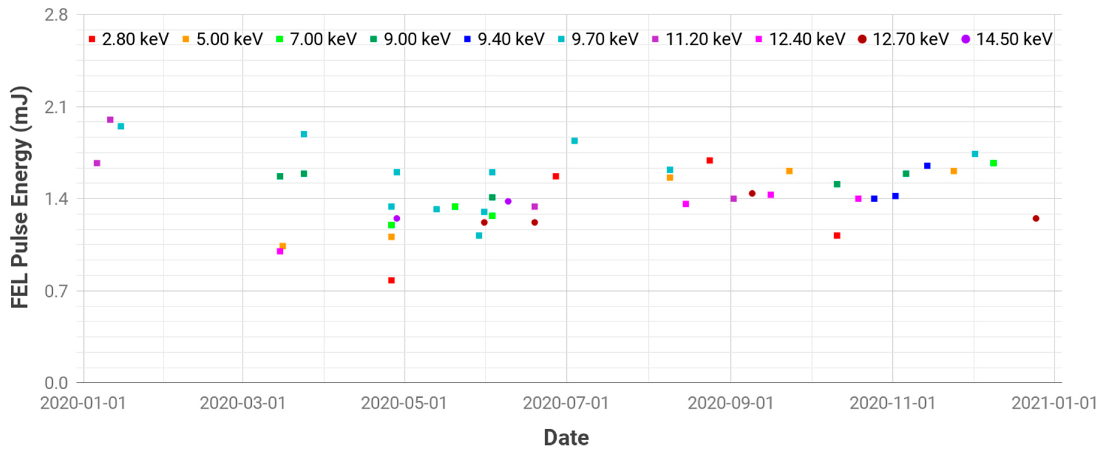
Since the user service started, we have tried to continuously improve the FEL performance, and providing the best FEL pulse energy has been pursued as a first priority. For that purpose, FEL tuning has been conducted every week before user service. Figure 2 shows the measurement results of the FEL pulse energy in 2020. The horizontal axis is dated from January to December and the vertical axis is the FEL pulse energy. Different colors show the provided photon energies for each user service. Note that most of the user services in the hard X-ray beamline were provided with more than 1.2 mJ of pulse energy.
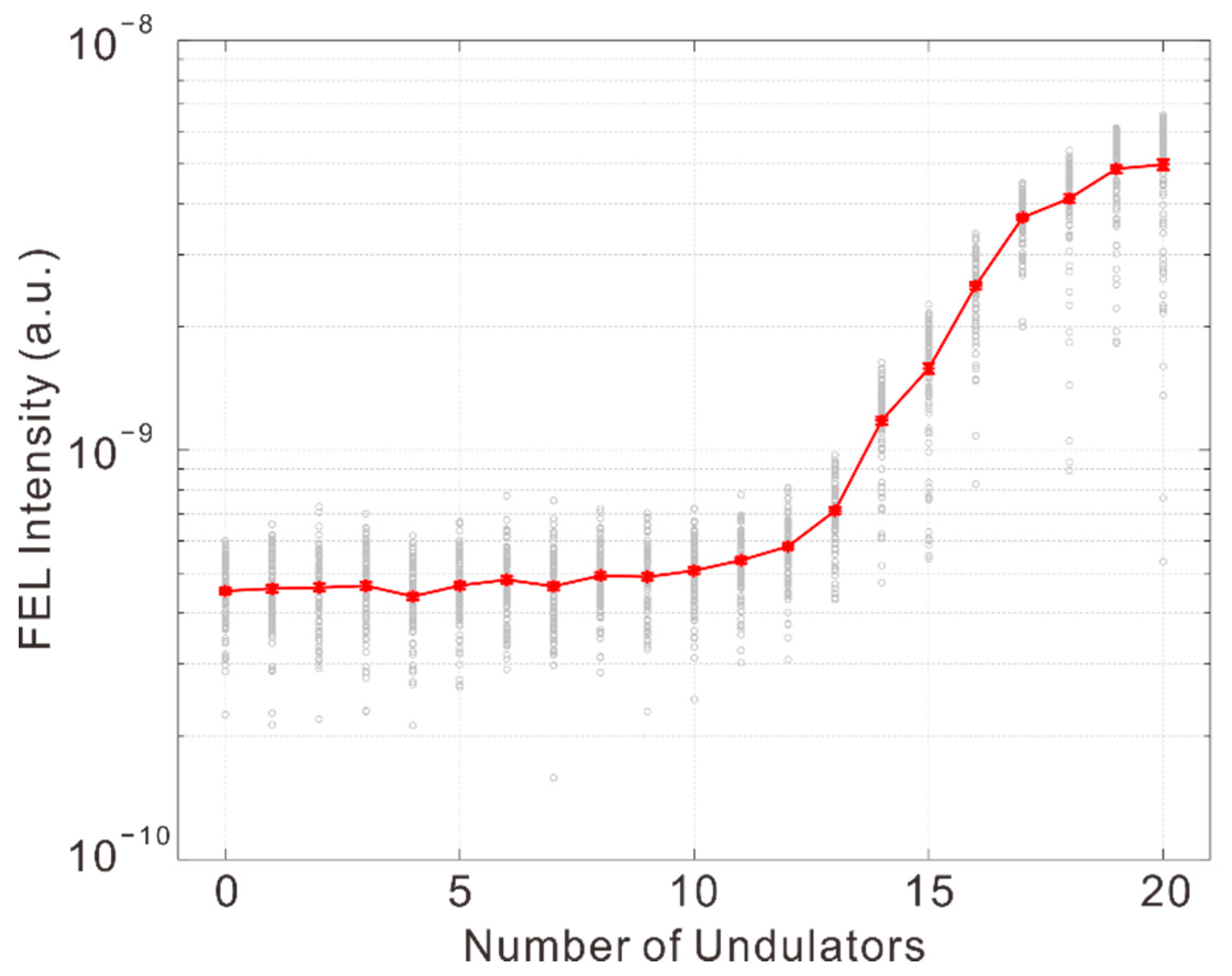
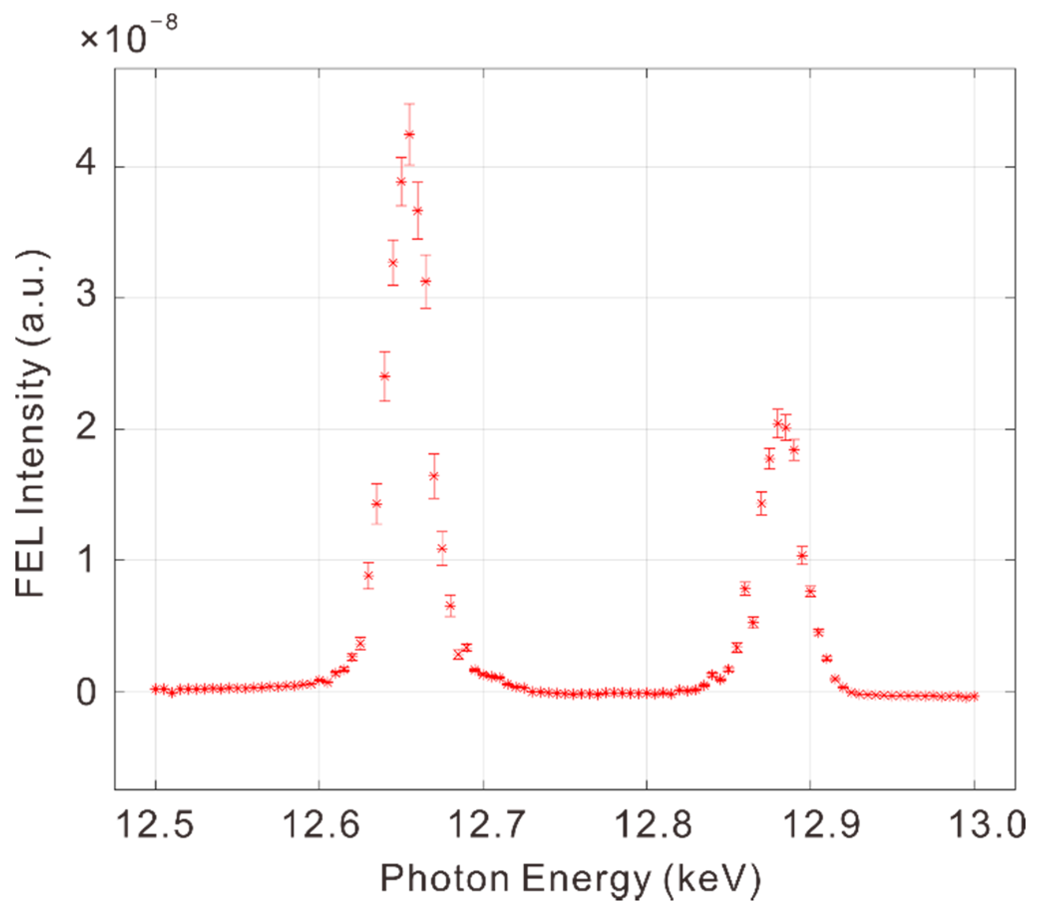
Increasing the photon energy range has been a second priority of FEL performance improvement. The design value of the maximum photon energy of the PAL-XFEL is 12.4 keV with 9.65 GeV electron beam energy for an undulator parameter K of 1.87. At PAL-XFEL, the maximum available energy of the electron beam is 11 GeV, and 14.5 keV FEL was achieved at the same undulator parameter K, with an electron beam energy of 10.44 GeV. The measured FEL pulse energy was 650 μJ [30]. This indicates that a higher photon energy can be obtained with a lower undulator parameter K, and a FEL saturation of 20 keV was achieved for the first time at the PAL-XFEL in 2020. The electron beam energy was 10.4 GeV and the undulator parameter K was 1.4. The measured FEL energy using the e-loss scan was 408 μJ, which corresponds to 1.26 × 10¹¹ photons/pulse. The measured FEL spectrum bandwidth was 25.3 eV rms (0.13% of the center photon energy), and the FEL pulse width (FWHM) was 11 fs. The undulator gap scan was conducted for 20 undulators to check the FEL saturation as shown in Figure 3. Here, quadratic undulator tapering was applied for the last six undulators, and the calculated gain length was 3.43 m.
Since the noisy spectrum and limited temporal coherence of SASE FELs, two self-seeding methods were proposed to overcome the drawback of the SASE FELs. The first method uses a single-crystal monochromator to generate a hard X-ray self-seeding FEL. When a seed X-ray pulse from the upstream undulators passes through a thin diamond crystal, a train of monochromatic wakes can be obtained after the seed X-ray pulse with a few tens of femtoseconds delay from the forward Bragg diffraction (FBD). A magnetic chicane adds a time delay in the electron beam to make an overlap with the monochromatic wake for the amplification in the downstream undulators [31,32,33]. The first experimental results of the hard X-ray self-seeding FEL were achieved in LCLS. 8.3 keV and X-ray pulses were obtained with a bandwidth of 0.4~0.5 eV and the average peak spectral intensity was increased by 1.7 times more than the SASE FEL case [8].
The second method of self-seeding FEL generation involves using a four-crystal monochromator in a Bragg reflection geometry [34] and an experimental result was achieved in the SACLA [35]. They succeeded in making a channel-cut Si (111) crystal monochromator with a small gap of 90 μm. A self-seeding FEL with a 3 eV bandwidth was obtained at 9.85 keV and the peak intensity was six times larger than the SASE FEL case. A relatively large bandwidth came from the large bandwidth of the seed beam and an energy chirp in the electron bunch. In the case of a Si (220) Bragg reflection and reduced energy chirp, the bandwidth of the self-seeding FEL was reduced down to 0.6 eV at 9.0 keV [36].
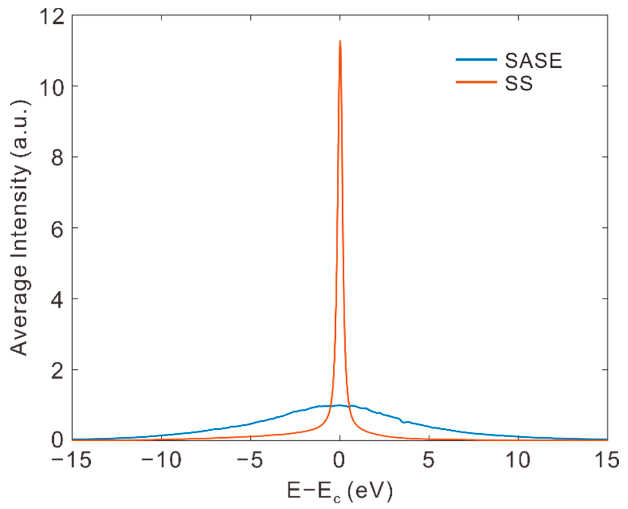
In the PAL-XFEL, two diamond crystals in the (100) and (110) orientations were installed in the middle of hard X-ray undulators to a generate self-seeding FEL with FBD [37]. The spectral purity and peak of the self-seeded FEL were consistently improved using a laser heater and optimized crystal conditions over a hard X-ray range from 3.5 keV to 14.6 keV. Figure 4 shows an intensity comparison between the SASE and self-seeding FELs of 9.7 keV photon energy. The peak brightness for self-seeded hard X-ray pulses was enhanced to 10 times greater than that of the SASE FEL over hard X-ray ranges. For example, the peak brightness of an X-ray at 9.7 keV was 3.2 × 1035 photons/ (s·mm2·mrad2·0.1% BW). This is the highest peak brightness ever achieved for FEL pulses. Thanks to the ultrabright X-ray pulse with a narrow bandwidth and superior spectral purity, the SFX experiment results using the seeded FEL showed better data quality with high resolution compared with the SASE FEL [38].
The optical laser pump and X-ray probe methods are widely used in the XFEL experiments for molecular and structure dynamics studies, and this method is being extended to the X-ray pump and X-ray probe experiment. Two-color FEL generation was proposed for the first time in 1994, using an infrared FEL with an optical cavity [39]. After that, two-color FEL generation has evolved into two directions depending on the generation methods of different photon energies. The former uses groups of undulators tuned in different ways, and the latter uses different energies of electron beams or different energy parts of an electron beam. In the former case, an electron beam with a small energy spread is sent through two groups of undulators with different undulator parameters K, to generate different wavelength FELs. The magnetic chicane between two undulator groups can be used to control the delay between two FEL pulses. Hard X-ray two-color FELs were obtained in the LCLS for the first time [40,41]. A drawback of this method is that the wavelength tuning range is limited to the variable range of the undulator parameter K. The LCLS undulators were planar, permanent-magnet based, fixed gap undulators. The magnet poles had canted angles to change the undulator parameter K from 3.47 to 3.51. The small range of the undulator parameters K limited the wavelength difference of the two-color FELs within 2%. In the SACLA, variable gap undulators were used to increase the wavelength separation by more than 30% [42]. Two-color FEL generation was tried at the PAL-XFEL to extend the research capabilities to the X-ray pump and X-ray probe experiment. Figure 5 shows the measured photon energy and intensity of generated two-color FELs using a single electron bunch. The pump pulse was generated with eight upstream undulators of the self-seeding section, and the probe pulse was generated with 12 downstream undulators. The energy separation of the two FEL pulses was 200 eV at a 12.7 keV photon energy. The measured FEL pulse energies were 10.7 and 55.8 μJ for the pump and probe pulse, respectively. The time delay between the two pulses was controlled from 0 to 120 fs using the magnetic chicane installed at the self-seeding section.
4. Recent Progress in Beamlines
4.1. Optical Laser Pump with Various Wavelengths and XFEL Probe Experiments
The femtosecond X-ray scattering (FXS) endstation at the hard X-ray beamline is dedicated to time-resolved X-ray diffraction experiments for single-crystal materials [20]. The optical laser pump and X-ray probe experiments enable the studying of ultrafast dynamics of the four fundamental physical degrees of freedom (lattice, charge, spin, and orbital), for which behaviors in the time domain bear intriguing physics associated with photoexcited states of matter. The fact that these physical degrees of freedom are coupled to one another makes it challenging to identify the individual origin accounting for the photoinduced change of the X-ray diffraction signal. An effective way to resolve this difficulty is employing an optical laser pump with different wavelengths that allows for selective photoexcitation for the individual degrees of freedom. For an insulating material with an electronic band gap of 1.55 eV, the laser beam with wavelength (λoptical) = 800 nm excites the valence electrons across the band gap. On the other hand, for a material with an optical phonon state at 82 meV, the beam with λoptical = 15 μm dominantly provokes the phonon mode. Therefore, it becomes possible to discriminate the trigger of the transient X-ray diffraction and unveil the underlying physics. The FXS endstation has made a continuous effort to establish optical laser sources in a wide range of wavelengths (λoptical).
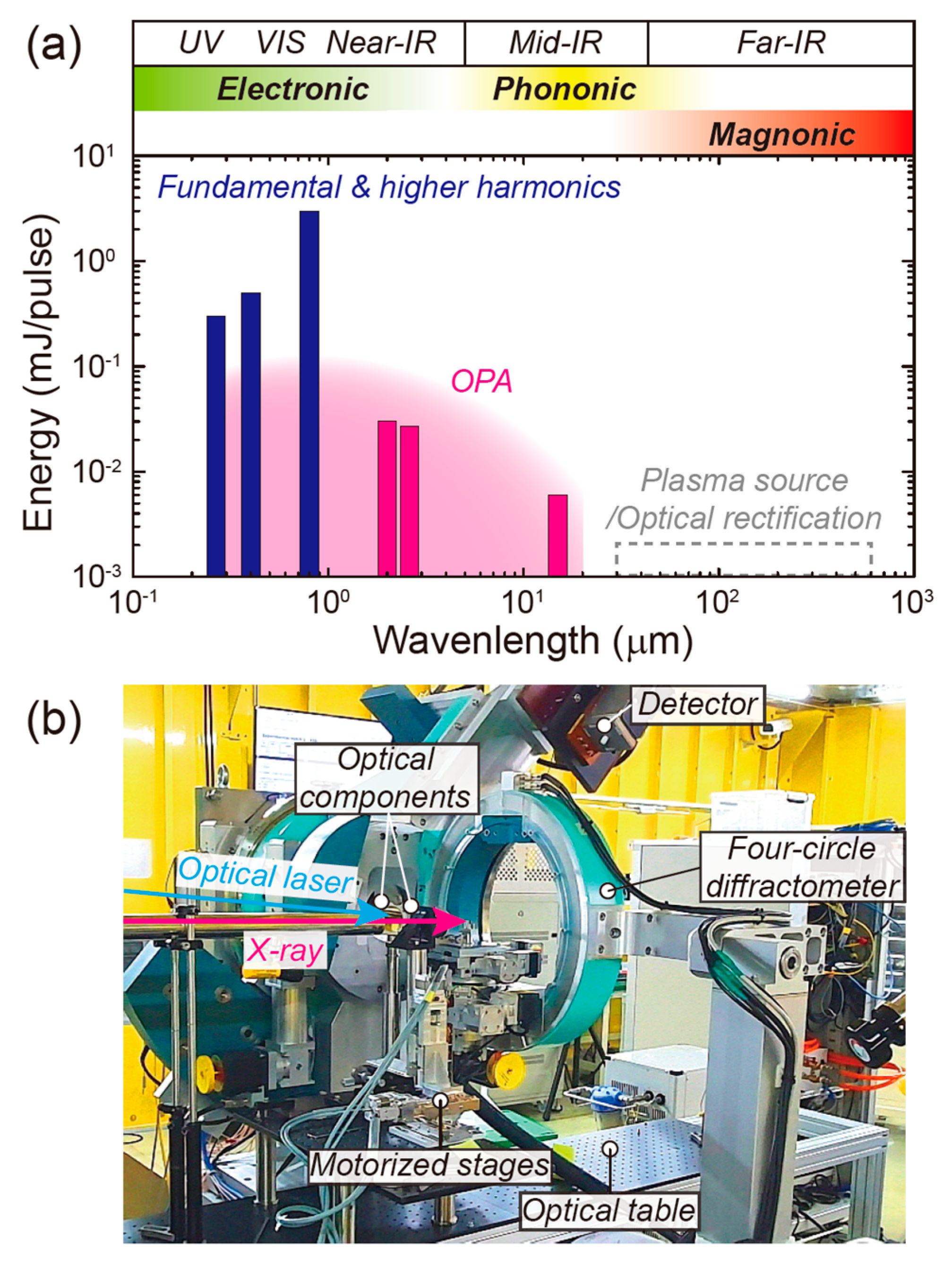
Figure 6a summarizes the optical laser wavelengths and their maximum energies realized at the FXS endstation so far [43]. The optical laser provides an 800 nm wavelength fundamental beam (the maximum energy = 3 mJ/pulse), which is also exploited to produce the second (400 nm) and third (266 nm) harmonic beams. In addition to these wavelengths, an optical parametric amplifier (TOPAS Prime, Light Conversion Ltd., Lithuania) is used in combination with a frequency mixer and a difference frequency generation unit to generate the laser beam in the λoptical range between 240 nm and 15 μm. In this case, the beam energy becomes orders of magnitude smaller (several or tens of microjoules) than the fundamental λoptical, but the maximum fluence of ~10–102 mJ/cm2 is still achievable by focusing the laser spot. The FXS endstation has a future plan to extend the available λoptical range further up to several hundreds of microns based on the plasma source [44], along with optical rectification using a LiNbO3 crystal [45]. This λoptical range corresponds to the energy region where antiferromagnets typically host magnon excitations. This is considered essential for studying the influence of the magnon on the physical degrees of freedom mirrored in the X-ray diffraction signals.
In parallel with establishing a variety of optical laser sources, it is important to effectively deliver the laser beam to the sample on a goniometer. In particular, for the laser beam with an λoptical of tens or hundreds of microns, the beam intensity is substantially reduced by air scattering or absorption by water molecules in the air. A vacuum sample chamber or a beam path with flowing dried gas is required in the design while avoiding any collision with the four-circle diffractometer. In addition, one needs to place other optical components close to the sample in order to manipulate the optical laser path and the spot size feasible for the pump–probe experiment. The FXS endstation uses an optical table near the diffractometer and installs several motorized stages to optimize the position of the optical components (Figure 6b). The combined efforts to diversify the optical laser sources and facilitate their use along with the X-ray diffraction experiment could advance the FXS endstation to become specialized for investigating condensed matter physics and materials science.
4.2. Time-Resolved X-ray Absorption Spectroscopy with Tender X-ray FEL
Time-resolved X-ray absorption spectroscopy (TR-XAS) is one of the major experimental tools used in the chemical science program at PAL-XFEL. X-ray absorption spectroscopy is based on the electron transition between the core-level orbital and empty valence orbital. Because X-ray-induced electron transition starts from excitation at the core-level orbital, the X-ray absorption spectrum has atomic selectivity. The X-ray absorption spectrum is also affected by the energy level of the empty valence orbitals, which can be directly related to the structural and electrical environment around specific atoms. Therefore, it is possible to understand the electronic structure, spin state, and charge distribution, as well as the atomic structure, from the X-ray absorption spectrum. Applying pump–probe experiments, the TR-XAS can provide information about the structural and electronic changes during chemical reactions. Investigation of the photoinduced processes within sub-picoseconds (i.e., the natural timescales of elementary chemical reactions) by X-ray is now possible with femtosecond X-rays from an XFEL.
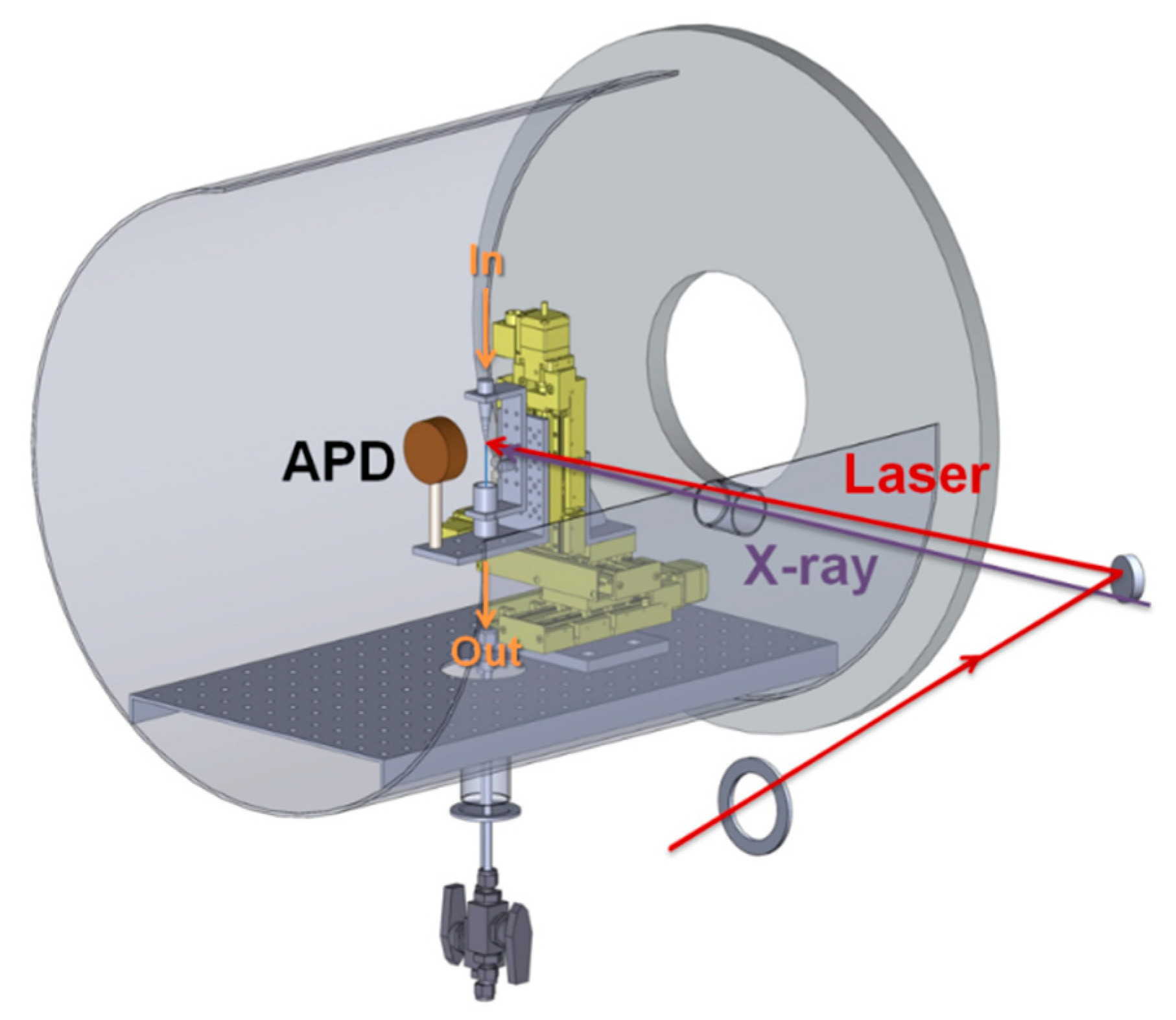
Hard X-ray TR-XAS at the PAL-XFEL is possible at both FXL and CXI endstations [20,46]. The difference between the two endstations is the focusing optics: compound refractive lens (CRL) for the FXL endstation and Kirkpatrick–Baez (K–B) mirror for the CXI endstation (Figure 7). For optimization of the performance of TR-XAS in a wide range of X-ray energy, K–B mirror based X-ray focus is an optimum choice. Therefore, we installed a time-resolved X-ray absorption measuring system at the CXI endstation [47].
For TR-XAS measurement, a monochromatized FEL using a double-crystal monochromator (DCM) is mandatory to increase the energy resolution. While passing through the DCM, the XFEL path length shows energy dependence. For example, at higher Bragg angles (low X-ray energy such as 2.8 keV, Ru L3-edge), a 10 eV energy change causes a 1 ps difference in arrival time of the XFEL to the sample. In experiments at the PAL-XFEL using DCM, the different arrival times of the FEL at different energy levels can be corrected by considering the geometric beam path difference inside the DCM.
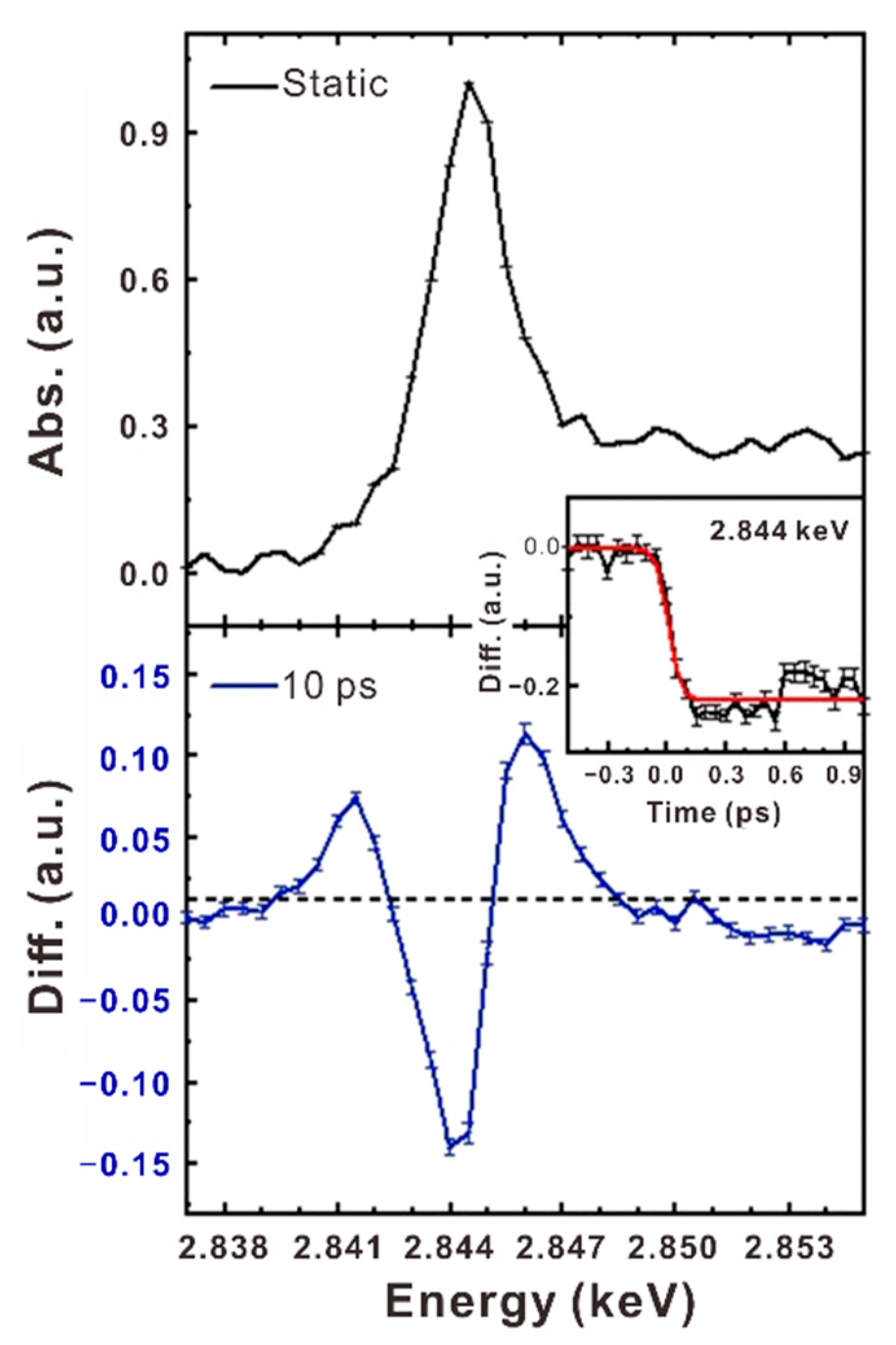
Herein, we introduce one representative result. The TR-XAS setup is shown in Figure 7. The chamber can provide a vacuum environment (~1 mbar) or 1 atm He environment to minimize the loss of X-ray flux. The liquid-phase sample is circulated through a 100 or 150 μm thickness round nozzle using a magnetic gear pump. A focused 20 × 20 μm2 (FWHM) X-ray beam with 60 Hz was used, and a 400 nm optical laser was delivered on the sample at 30 Hz with a pulse energy of 24 μJ. The optical laser [33] is focused to about 100–200 μm at the sample position. To minimize the group velocity mismatch between the X-ray and the laser, they have collinear geometry. The avalanche photodiode (APD) monitors the total fluorescence yield from the sample. APD is shielded by 1.6 μm Al foil to block the scattered pump laser. The measured X-ray fluorescence signal is normalized by the I0 signal, which is collected by the quadrant beam position monitor (QBPM). After data normalization at each X-ray pulse, the transient spectrum is obtained by the subtraction from a pumped to unpumped X-ray absorption signal. Ru L3-edge TR-XAS results are shown in Figure 8. The sample is an aqueous solution of 50 mM [Ru(bpy)3]2+ (Tris(bipyridine) ruthenium(II) chloride, Sigma-Aldrich) that is well known as a photosensitizer with intra-electron transfer. The top panel of Figure 8 shows the ground static spectrum, and the bottom panel shows the transient X-ray absorption spectrum at 10 ps time delay. These data were collected over 15 s (450 shots for laser-on XFEL, 450 shots for laser-off XFEL) at each energy point. The center panel of Figure 8 presents the kinetic spectrum at 2.844 KeV, which is a mean of 150 shots for laser on and off. The instrument response function (IRF) was fitted to 136 ± 44 fs.
Currently, TR-XAS experiments can run smoothly at the PAL-XFEL for the study of various chemical and biological fields. In photoactivated reactions, the 136 fs IRF from the PAL-XFEL is not sufficiently short. One way to reduce the IRF is to reduce the group velocity mismatch by using a thinner liquid jet. Currently, the liquid injector at the PAL-XFEL provides a 100 μm or 150 μm round nozzle. We plan to reduce the liquid jet thickness and increase the jet stability so that the IRF can be reduced to 100 fs.
Recently, the PAL-XFEL succeeded in the generation of a bright self-seeded FEL, which had a peak intensity more than fivefold stronger than that of a normal XFEL from SASE. We plan to use self-seeded FEL with an energy scanning function. We expect the TR-XAS with a self-seeding FEL to be able to measure signals even from a sample at very low concentration with an increased signal-to-noise ratio.
4.3. Noble Sample Delivery System Developed for Time-Resolved SFX
The sample delivery instrument is one of the major components to perform serial femtosecond crystallography (SFX) at XFEL facilities. The instrument supports the experimental scheme of “diffract-before-destruct” by continuously supplying fresh microcrystals to the X-ray interaction point. In particular, since protein crystals are quite sensitive to the sample environment (humidity, temperature, etc.), the sample delivery technique should provide a proper sample environment to keep the protein crystals in a stable condition during the delivery process. So far, many attempts have been made to develop sample delivery instruments, such as the gas dynamic virtual nozzle (GDVN) [48,49], electrospinning [50], lipidic cubic phase injector [51], acoustic injector [52], viscous medium extruder [21,53,54,55], goniometer-based scanning [56], and micro tubing [26].
Here, we developed a microliter volume (MLV) syringe injector driven by a high-performance liquid chromatography (HPLC) pump. Many crystallization processes of membrane proteins with LCP typically use MLV syringes. In addition, to reduce sample consumption through sample injection, soluble microcrystals are uniformly mixed with a highly viscous medium using MLV syringes. This novel instrument makes it possible to directly use the syringe itself as a sample injector, which helps to increase experiment efficiency through a simpler preparation procedure for sample injection.
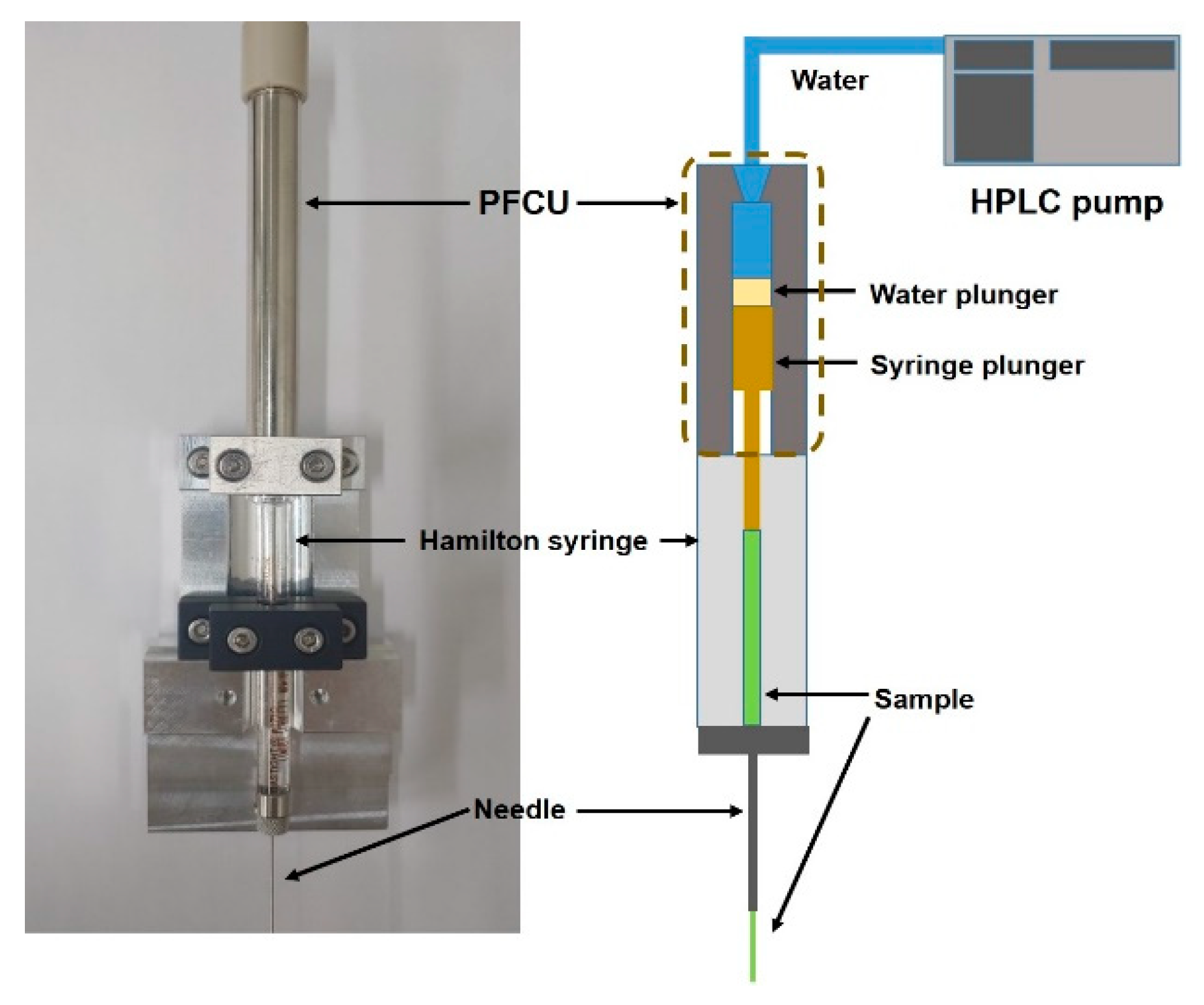
Figure 9 shows a photo of the injector equipment assembly. It has a plunger fine control unit (PFCU), MLV syringe, and needle. The PFCU is composed of an SUS cylinder with a single channel at the center, a water plunger made of Teflon, and a PEEK cap that closes one side of the SUS cylinder with a 10-32 tap. The internal dimension of the cylinder for water flow is 5 mm in diameter and 102 mm in length when the water plunger is inserted in the channel. This length can cover the whole plunger travel length of most MLV syringes. To manipulate the plunger position, the syringe plunger should be inserted into the PFCU until it reaches one end of the Teflon water plunger. The syringe plunger plate was modified to an SUS cylinder with 4.8 mm in diameter and 9.0 mm in height. To perform crystallography experiments, the viscous medium mixed with microcrystals is filled inside of a gastight Hamilton syringe (1700 series, volume: 100 μL). The loaded sample can be extruded through a syringe needle via fine control of the plunger. To control the sample flow rate exactly, the PFCU is driven by the HPLC pump. The operational scheme is shown in Figure 9. The upper PEEK cap serves as a connection point with an HPLC pump through a PEEK tubing (OD: 1/16 inch). The HPLC pump (LC-20AD, Shimadzu) provides water to transmit proper pressure to the syringe flange for extrusion of the sample. The pump provides the maximal pressure of 40 MPa, with flow rates between 0.0001 and 10.00 mL/min. In addition, it is quite advantageous to deliver samples in an isocratic condition. The viscous sample is extruded to the X-ray interaction point through a 22s-gauge Hamilton SUS needle (ID: ~150 μm).
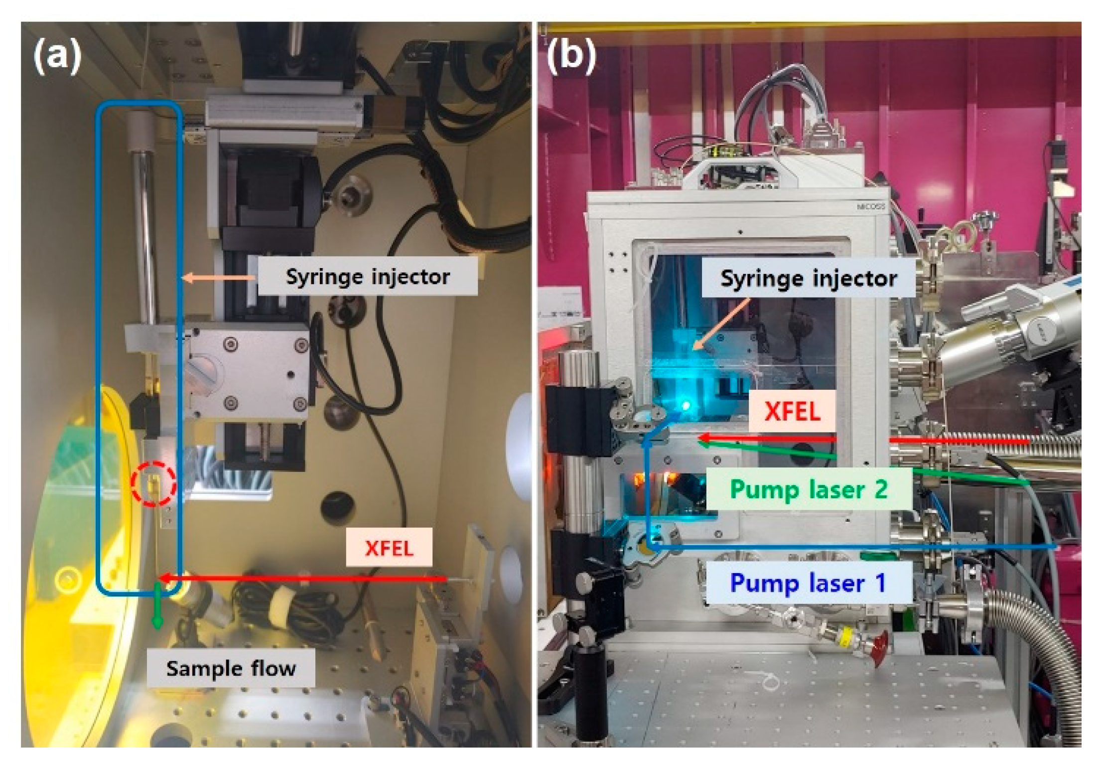
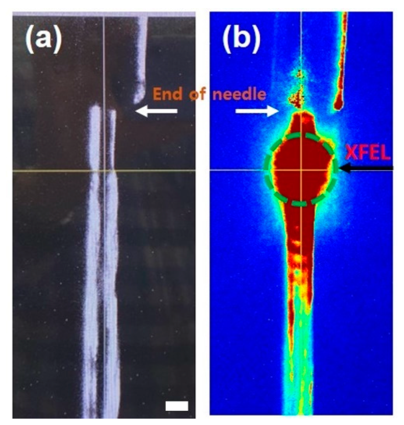
The MLV syringe injector is designed to be operated inside of the MICOSS, which is an SFX dedicated sample chamber established at the PAL-XFEL [21]. Figure 10a shows the installation photo of the injector. The unique feature is the simultaneous application of multiple optical laser pumps, which is feasible for the time-resolved study of macromolecules. Owing to the transparent glass barrel of the Hamilton syringe, an optical laser beam can penetrate into the syringe and illuminate the samples directly. Figure 10b shows the incident geometry of two optical laser pulses at different wavelengths. Pump laser 1 illuminates the glass barrel of the MLV syringe to initiate a specific structural state of molecules (red dotted circle region in Figure 10a. Pump laser 2 is aligned to overlap with XFEL pulses just below the end of the needle to probe the structural changes according to various time delays. Figure 11a,b shows the microscope images during the experiments near the end of the needle along parallel and perpendicular directions to the XFEL beam, respectively.
At the SFX endstation of the PAL-XFEL, several sample delivery systems have been developed and are now operational for user experiments. In addition to the liquid jet injector with GDVN, a carrier matrix delivery (CMD) injector is available to study the ground state and structural dynamics of macromolecules [21]. Along with these conventional injectors, the novel syringe injector will expand the opportunity to study a specific chemical state transition and the related structural dynamics of macromolecules in a fast time domain with XFELs.
4.4. Fourier-Transform Holography (FTH)/Forward Scattering Endstation in SSS
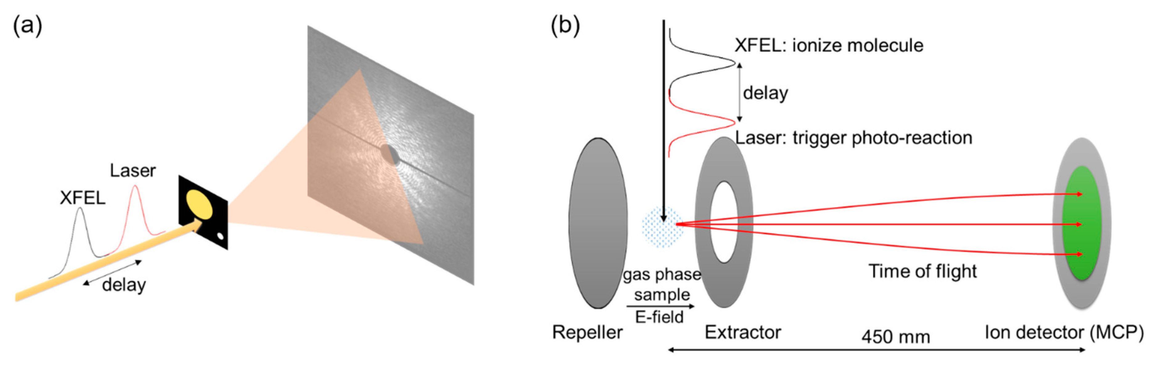
The FTH (Figure 12a)/forward scattering (Figure 12b) endstation opened in 2021 for time-resolved X-ray imaging experiments involving a thin solid target mounted on a sample stage within a micro-sized domain. The primary purpose of this endstation is the FTH based on the interference between direct X-ray and scattered X-rays through the sample, measuring the transition dynamics on electric or magnetic properties in the spatial domain. The image resolution is about 100 nm, which depends on the coherence of the X-ray, the reference hole, and the sample to detector distance [57]. The endstation consists of a house for the sample environment, an optical pump laser, a control system, and a data acquisition system. The thin solid target can be mounted perpendicularly to the FEL beam direction with temperature control. A large-area charge coupled device (CCD) detector (MTE 2048b. Teledyne Princeton Inc, Trenton, NJ, USA) is equipped, facing the FEL beam in a separate vacuum chamber with 100 nm parylene/100 nm aluminum (Luxel Corporation, Friday Harbor, WA, USA). The distance from the sample to the detector is flexible from 200 mm to 400 mm depending on each experimental requirement. The CCD chamber is mounted on a linearly movable bellow which is a sled type with rails in a vacuum. Furthermore, a 2 mm beam block is fixed with a wire in front of the CCD to protect it from an intense beam. The sample stage and CCD chamber have independent XYZ motion for the alignment. The recorded diffraction images are stored at the main terminal and reconstructed in real space using software operating the Fourier transformation under the reconstruction algorithm. An ion spectrometer to measure ion time-of-flight mass spectrometry (ITOF) is also mounted along with electrodes and an MCP detector with a phosphor screen (double prime, Photek, Hastings, UK). The flight time is measured by a 5 GSPS digitizer (Adq7DC, Teledyne SP Devices, Linköping, Sweden), and the signal intensity is normalized by the incident XFEL intensity measured by the I0 monitor. After the photoreaction is initiated by the optical laser, the products of the photoreaction are ionized by the XFEL with a time delay. Then, the mass of products can be analyzed at fs time resolution. For further development, a magnetic field supplier with a circular polarized XFEL and a high-speed large-area CCD will be installed in the future.
5. Summary and Future Plans
We reported the PAL-XFEL’s efforts to improve the performance of the facility and provide a better experimental environment for users. The FEL pulse energy has been increased continuously to provide more photons for beamline experiments, and FELs with energies of more than 1.2 mJ are delivered in all photon energy ranges. The maximum photon energy was increased from 12 keV to 20 keV using a higher electron beam energy and lower undulator parameter K. To overcome the limitations of an SASE FEL, self-seeding was prepared, and the peak brightness was improved tenfold compared to SASE FEL in all photon energy ranges. Two-color FEL generation was applied to extend the research capabilities, and two FEL pulses with a 200 eV energy difference were generated by using a different undulator parameter K in the upstream and downstream undulators of the self-seeding section. In beamline experiments, it is expected that the extended pump laser wavelengths of the XSS beamline will make it possible to study various materials and access more physical degrees of freedom. Furthermore, improving the experimental time resolution at the FXL endstation will be an essential step for studying many veiled ultrafast phenomena. Lastly, the newly developed sample injector for the SFX and the capability of the XES/XAS endstation for various sample phases will lead to new research areas and increase the number of XFEL users.
The user beamtime of the PAL-XFEL will increase to 190 days in 2022, thereby increasing the number of beamtime shifts available to users. Accordingly, the burden of the supporting staff at the PAL-XFEL should be eased in line with the increased user experiments. As one possible approach, we plan to introduce techniques to increase the convenience and stability of the experiment, such as an automatic sample exchange system, remote control for wavelength, polarization, and intensity of the optical laser, and RF phase shifter for time-delay control.
Author Contributions
I.E. and C.K. planed the article and organized sections, and the following authors contributed to each section. Section 2.1: C.K., Section 2.2: I.E., 3: H.Y., I.N., M.H.C., C.H.S., G.K., C.-K.M., H.H., H.-S.K. and C.K., Section 4.1: S.H.C. and I.E. Section 4.2: J.H.L., D.N. and R.M., Section 4.3: J.P. and S.P., Section 4.4: S.H.P. All authors have read and agreed to the published version of the manuscript.
Funding
This work was supported by the Ministry of Science and Information, Communications & Technology (ICT) of Korea (grant number 2018R1A6B4023605). D.N. was also supported by the National Research Foundation of Korea (grants NRF-2019R1A6B2A02098631 and NRF-2021R1F1A1051444)). J.P. was also supported by National Research Foundation of Korea (grant No. NRF-2017M3A9F6029736).
Acknowledgments
The authors acknowledge all PAL-XFEL staff members who participated in operations and R & D.
Conflicts of Interest
The authors declare no conflict of interest.
References
- Emma, P.; Akre, R.; Arthur, J.; Bionta, R.; Bostedt, C.; Bozek, J.; Brachmann, A.; Bucksbaum, P.; Coffee, R.; Decker, F.J.; et al. First lasing and operation of an angstrom-wavelength free-electron laser. Nat. Photonics 2010, 4, 641–647. [Google Scholar] [CrossRef]
- Ishikawa, T.; Aoyagi, H.; Asaka, T.; Asano, Y.; Azumi, N.; Bizen, T.; Ego, H.; Fukami, K.; Fukui, T.; Furukawa, Y.; et al. A compact X-ray free-electron laser emitting in the sub-angstrom region. Nat. Photonics 2012, 6, 540–544. [Google Scholar] [CrossRef]
- Kang, H.S.; Min, C.K.; Heo, H.; Kim, C.; Yang, H.; Kim, G.; Nam, I.; Baek, S.Y.; Choi, H.J.; Mun, G.; et al. Hard X-ray free-electron laser with femtosecond-scale timing jitter. Nat. Photonics 2017, 11, 708–713. [Google Scholar] [CrossRef]
- Decking, W.; Abeghyan, S.; Abramian, P.; Abramsky, A.; Aguirre, A.; Albrecht, C.; Alou, P.; Altarelli, M.; Altmann, P.; Amyan, K.; et al. A MHz-repetition-rate hard X-ray free-electron laser driven by a superconducting linear accelerator. Nat. Photonics 2020, 14, 391–397. [Google Scholar] [CrossRef]
- Prat, E.; Abela, R.; Aiba, M.; Alarcon, A.; Alex, J.; Arbelo, Y.; Arrell, C.; Arsov, V.; Bacellar, C.; Beard, C.; et al. A compact and cost-effective hard X-ray free-electron laser driven by a high-brightness and low-energy electron beam. Nat. Photonics 2020, 14, 748–754. [Google Scholar] [CrossRef]
- Huang, Z.R.; Kim, K.J. Review of X-ray free-electron laser theory. Phys. Rev. Spec. Top.-Accel. Beams 2007, 10, 034801. [Google Scholar] [CrossRef]
- Feldhaus, J.; Saldin, E.L.; Schneider, J.R.; Schneidmiller, E.A.; Yurkov, M.V. Possible application of X-ray optical elements for reducing the spectral bandwidth of an X-ray SASE FEL. Opt. Commun. 1997, 140, 341–352. [Google Scholar] [CrossRef] [Green Version]
- Amann, J.; Berg, W.; Blank, V.; Decker, F.J.; Ding, Y.; Emma, P.; Feng, Y.; Frisch, J.; Fritz, D.; Hastings, J.; et al. Demonstration of self-seeding in a hard-X-ray free-electron laser. Nat. Photonics 2012, 6, 693–698. [Google Scholar] [CrossRef]
- Lee, H.J.; Ahn, Y.; Marks, S.D.; Landahl, E.C.; Zhuang, S.H.; Yusuf, M.H.; Dawber, M.; Lee, J.Y.; Kim, T.Y.; Unithrattil, S.; et al. Structural Evidence for Ultrafast Polarization Rotation in Ferroelectric/Dielectric Superlattice Nanodomains. Phys. Rev. X 2021, 11, 031031. [Google Scholar] [CrossRef]
- Choi, E.H.; Kim, J.G.; Kim, J.; Ki, H.; Lee, Y.; Lee, S.; Yoon, K.; Kim, J.; Kim, J.; Ihee, H. Filming ultrafast roaming-mediated isomerization of bismuth triiodide in solution. Nat. Commun. 2021, 12, 4732. [Google Scholar] [CrossRef] [PubMed]
- Kim, J.G.; Nozawa, S.; Kim, H.; Choi, E.H.; Sato, T.; Kim, T.W.; Kim, K.H.; Ki, H.; Kim, J.; Choi, M.; et al. Mapping the emergence of molecular vibrations mediating bond formation. Nature 2020, 582, 520–524. [Google Scholar] [CrossRef]
- Pace, E.J.; Coleman, A.L.; Husband, R.J.; Hwang, H.; Choi, J.; Kim, T.; Hwang, G.; Chun, S.H.; Nam, D.; Kim, S.; et al. Intense Reactivity in Sulfur-Hydrogen Mixtures at High Pressure under X-ray Irradiation. J. Phys. Chem. Lett. 2020, 11, 1828–1834. [Google Scholar] [CrossRef]
- Assefa, T.A.; Cao, Y.; Banerjee, S.; Kim, S.; Kim, D.; Lee, H.; Kim, S.; Lee, J.H.; Park, S.Y.; Eom, I.; et al. Ultrafast X-ray diffraction study of melt-front dynamics in polycrystalline thin films. Sci. Adv. 2020, 6, eaax2445. [Google Scholar] [CrossRef] [PubMed] [Green Version]
- Hwang, H.; Galtier, E.; Cynn, H.; Eom, I.; Chun, S.H.; Bang, Y.; Hwang, G.C.; Choi, J.; Kim, T.; Kong, M.; et al. Subnanosecond phase transition dynamics in laser-shocked iron. Sci. Adv. 2020, 6, eaaz5132. [Google Scholar] [CrossRef]
- Kim, K.H.; Amann-Winkel, K.; Giovambattista, N.; Spah, A.; Perakis, F.; Pathak, H.; Parada, M.L.; Yang, C.; Mariedahl, D.; Eklund, T.; et al. Experimental observation of the liquid-liquid transition in bulk supercooled water under pressure. Science 2020, 370, 978–982. [Google Scholar] [CrossRef]
- Lee, J.W.; Kim, M.; Kang, G.; Vinko, S.M.; Bae, L.; Cho, M.S.; Chung, H.K.; Kim, M.; Kwon, S.; Lee, G.; et al. Investigation of Nonequilibrium Electronic Dynamics of Warm Dense Copper with Femtosecond X-ray Absorption Spectroscopy. Phys. Rev. Lett. 2021, 127, 175003. [Google Scholar] [CrossRef]
- Britz, A.; Attar, A.R.; Zhang, X.; Chang, H.T.; Nyby, C.; Krishnamoorthy, A.; Park, S.H.; Kwon, S.; Kim, M.; Nordlund, D.; et al. Carrier-specific dynamics in 2H-MoTe2 observed by femtosecond soft X-ray absorption spectroscopy using an X-ray free-electron laser. Struct. Dynam. 2021, 8, 014501. [Google Scholar] [CrossRef] [PubMed]
- Kim, S.; Kim, Y.; Kim, J.; Choi, S.; Yun, K.; Kim, D.; Lim, S.Y.; Kim, S.; Chun, S.H.; Park, J.; et al. Ultrafast Carrier-Lattice Interactions and Interlayer Modulations of Bi2Se3 by X-ray Free-Electron Laser Diffraction. Nano Lett. 2021, 21, 8554–8562. [Google Scholar] [CrossRef]
- Uemura, Y.; Ismail, A.S.M.; Park, S.H.; Kwon, S.; Kim, M.; Niwa, Y.; Wadati, H.; Elnaggar, H.; Frati, F.; Haarman, T.; et al. Femtosecond Charge Density Modulations in Photoexcited CuWO4. J. Phys. Chem. C 2021, 125, 7329–7336. [Google Scholar] [CrossRef]
- Park, J.; Eom, I.; Kang, T.H.; Rah, S.; Nam, K.H.; Park, J.; Kim, S.; Kwon, S.; Park, S.H.; Kim, K.S.; et al. Design of a hard X-ray beamline and end-station for pump and probe experiments at Pohang Accelerator Laboratory X-ray Free Electron Laser facility. Nucl. Instrum. Methods Phys. Res. Sect. A Accel. Spectrom. Detect. Assoc. Equip. 2016, 810, 74–79. [Google Scholar] [CrossRef]
- Park, J.; Kim, S.; Kim, S.; Nam, K.H. Multifarious injection chamber for molecular structure study (MICOSS) system: Development and application for serial femtosecond crystallography at Pohang Accelerator Laboratory X-ray Free-Electron Laser. J. Synchrotron Radiat. 2018, 25, 323–328. [Google Scholar] [CrossRef]
- Sung, D.; Nam, D.; Kim, M.J.; Kim, S.; Kim, K.S.; Park, S.Y.; Hwang, S.M.; Jung, C.; Lee, H.; Cho, D.H.; et al. Single-Shot Coherent X-ray Imaging Instrument at PAL-XFEL. Appl. Sci.l 2021, 11, 5082. [Google Scholar] [CrossRef]
- Kim, J.; Kim, H.Y.; Park, J.; Kim, S.; Kim, S.; Rah, S.; Lim, J.; Nam, K.H. Focusing X-ray free-electron laser pulses using Kirkpatrick—Baez mirrors at the NCI hutch of the PAL-XFEL. J. Synchrotron Radiat. 2018, 25, 289–292. [Google Scholar] [CrossRef] [PubMed] [Green Version]
- Cho, D.H.; Shen, Z.; Ihm, Y.; Wi, D.H.; Jung, C.; Nam, D.; Kim, S.; Park, S.Y.; Kim, K.S.; Sung, D.; et al. High-Throughput 3D Ensemble Characterization of Individual Core—Shell Nanoparticles with X-ray Free Electron Laser Single-Particle Imaging. ACS Nano 2021, 15, 4066–4076. [Google Scholar] [CrossRef] [PubMed]
- Lee, D.; Baek, S.; Park, J.; Lee, K.; Kim, J.; Lee, S.J.; Chung, W.K.; Lee, J.L.; Cho, Y.; Nam, K.H. Nylon mesh-based sample holder for fixed-target serial femtosecond crystallography. Sci. Rep. 2019, 9, 6971. [Google Scholar] [CrossRef] [PubMed] [Green Version]
- Lee, D.; Park, S.; Lee, K.; Kim, J.; Park, G.; Nam, K.H.; Baek, S.; Chung, W.K.; Lee, J.L.; Cho, Y.; et al. Application of a high-throughput microcrystal delivery system to serial femtosecond crystallography. J Appl. Crystallogr. 2020, 53, 477–485. [Google Scholar] [CrossRef] [PubMed] [Green Version]
- Jang, H.; Kim, H.D.; Kim, M.; Park, S.H.; Kwon, S.; Lee, J.Y.; Park, S.Y.; Park, G.; Kim, S.; Hyun, H.; et al. Time-resolved resonant elastic soft X-ray scattering at Pohang Accelerator Laboratory X-ray Free Electron Laser. Rev. Sci. Instrum. 2020, 91, 083904. [Google Scholar] [CrossRef] [PubMed]
- Park, S.H.; Kim, M.; Min, C.K.; Eom, I.; Nam, I.; Lee, H.S.; Kang, H.S.; Kim, H.D.; Jang, H.Y.; Kim, S.; et al. PAL-XFEL soft X-ray scientific instruments and X-ray optics: First commissioning results. Rev. Sci. Instrum. 2018, 89, 055105. [Google Scholar] [CrossRef] [PubMed]
- Park, S.H.; Yoon, J.; Kim, C.; Hwang, C.; Kim, D.H.; Lee, S.H.; Kwon, S. Scientific instruments for soft X-ray photon-in/photon-out spectroscopy on the PAL-XFEL. J. Synchrotron Radiat. 2019, 26, 1031–1036. [Google Scholar] [CrossRef]
- Yang, H.; Kim, G.; Kang, H.S. First saturation of 14.5 keV free electron laser at PAL-XFEL. Nucl. Instrum. Methods Phys. Res. Sect. A Accel. Spectrom. Detect. Assoc. Equip. 2018, 911, 51–54. [Google Scholar] [CrossRef]
- Lindberg, R.R.; Shvyd’ko, Y.V. Time dependence of Bragg forward scattering and self-seeding of hard X-ray free-electron lasers. Phys. Rev. Spec. Top.-Accel. Beams 2012, 15, 050706. [Google Scholar] [CrossRef] [Green Version]
- Shvyd’ko, Y.; Lindberg, R. Spatiotemporal response of crystals in X-ray Bragg diffraction. Phys. Rev. Spec. Top.-Accel. Beams 2012, 15, 100702. [Google Scholar] [CrossRef] [Green Version]
- Geloni, G.; Kocharyan, V.; Saldin, E. A novel self-seeding scheme for hard X-ray FELs. J. Mod. Optic. 2011, 58, 1391–1403. [Google Scholar] [CrossRef]
- Saldin, E.L.; Schneidmiller, E.A.; Shvyd’ko, Y.V.; Yurkov, M.V. X-ray FEL with a meV bandwidth. Nucl. Instrum. Methods Phys. Res. Sect. A Accel. Spectrom. Detect. Assoc. Equip. 2001, 475, 357–362. [Google Scholar] [CrossRef]
- Inoue, I.; Osaka, T.; Hara, T.; Tanaka, T.; Inagaki, T.; Fukui, T.; Goto, S.; Inubushi, Y.; Kimura, H.; Kinjo, R.; et al. Generation of narrow-band X-ray free-electron laser via reflection self-seeding. Nat. Photonics 2019, 13, 319–322. [Google Scholar] [CrossRef]
- Matsumura, S.; Osaka, T.; Inoue, I.; Matsuyama, S.; Yabashi, M.; Yamauchi, K.; Sano, Y. High-resolution micro channel-cut crystal monochromator processed by plasma chemical vaporization machining for a reflection self-seeded X-ray free-electron laser. Opt. Express 2020, 28, 25706. [Google Scholar] [CrossRef] [PubMed]
- Min, C.K.; Nam, I.; Yang, H.; Kim, G.; Shim, C.H.; Ko, J.H.; Cho, M.H.; Heo, H.; Oh, B.; Suh, Y.J.; et al. Hard X-ray self-seeding commissioning at PAL-XFEL. J. Synchrotron Radiat. 2019, 26, 1101–1109. [Google Scholar] [CrossRef] [PubMed]
- Nam, I.; Min, C.K.; Oh, B.; Kim, G.; Na, D.; Suh, Y.J.; Yang, H.; Cho, M.H.; Kim, C.; Kim, M.J.; et al. High-brightness self-seeded X-ray free-electron laser covering the 3.5 keV to 14.6 keV range. Nat. Photonics 2021, 15, 435–441. [Google Scholar] [CrossRef]
- Jaroszynski, D.A.; Prazeres, R.; Glotin, F.; Ortega, J.M. 2-Color Free-Electron Laser Operation. Phys. Rev. Lett. 1994, 72, 2387. [Google Scholar] [CrossRef] [PubMed]
- Lutman, A.A.; Coffee, R.; Ding, Y.; Huang, Z.; Krzywinski, J.; Maxwell, T.; Messerschmidt, M.; Nuhn, H.D. Experimental Demonstration of Femtosecond Two-Color X-Ray Free-Electron Lasers. Phys. Rev. Lett. 2013, 110, 134801. [Google Scholar] [CrossRef]
- Marinelli, A.; Lutman, A.A.; Wu, J.; Ding, Y.; Krzywinski, J.; Nuhn, H.D.; Feng, Y.; Coffee, R.N.; Pellegrini, C. Multicolor Operation and Spectral Control in a Gain-Modulated X-Ray Free-Electron Laser. Phys. Rev. Lett. 2013, 111, 134801. [Google Scholar] [CrossRef] [PubMed] [Green Version]
- Hara, T.; Inubushi, Y.; Katayama, T.; Sato, T.; Tanaka, H.; Tanaka, T.; Togashi, T.; Togawa, K.; Tono, K.; Yabashi, M.; et al. Two-colour hard X-ray free-electron laser with wide tunability. Nat. Commun. 2013, 4, 2919. [Google Scholar] [CrossRef] [PubMed] [Green Version]
- Kim, M.; Min, C.K.; Eom, I. Laser systems for time-resolved experiments at the Pohang Accelerator Laboratory X-ray Free-Electron Laser beamlines. J. Synchrotron Radiat. 2019, 26, 868–873. [Google Scholar] [CrossRef] [Green Version]
- Cook, D.J.; Hochstrasser, R.M. Intense terahertz pulses by four-wave rectification in air. Opt. Lett. 2000, 25, 1210–1212. [Google Scholar] [CrossRef] [PubMed]
- Hirori, H.; Doi, A.; Blanchard, F.; Tanaka, K. Single-cycle terahertz pulses with amplitudes exceeding 1 MV/cm generated by optical rectification in LiNbO3. Appl. Phys. Lett. 2011, 98, 091106. [Google Scholar] [CrossRef]
- Park, J.; Nam, K.H.; Kim, S.; Kim, B.; Ko, I.S.; Cho, M. Construction status of CXI beamline at PAL-XFEL. Proc. SPIE 2015, 9512, 95121U. [Google Scholar]
- Kim, Y.; Nam, D.; Ma, R.; Kim, S.; Kim, M.-j.; Kim, J.; Eom, I.; Lee, J.H.; Kim, T.K. Development of an experimental apparatus to observe ultrafast phenomena by tender X-ray absorption spectroscopy at PAL-XFEL. J. Synchrotron Radiat. 2022, 29, 194–201. [Google Scholar] [CrossRef] [PubMed]
- Deponte, D.P.; Mckeown, J.T.; Weierstall, U.; Doak, R.B.; Spence, J.C.H. Towards ETEM serial crystallography: Electron diffraction from liquid jets. Ultramicroscopy 2011, 111, 824–827. [Google Scholar] [CrossRef]
- DePonte, D.P.; Weierstall, U.; Schmidt, K.; Warner, J.; Starodub, D.; Spence, J.C.H.; Doak, R.B. Gas dynamic virtual nozzle for generation of microscopic droplet streams. J. Phys. D Appl. Phys. 2008, 41, 195505. [Google Scholar] [CrossRef] [Green Version]
- Sierra, R.G.; Laksmono, H.; Kern, J.; Tran, R.; Hattne, J.; Alonso-Mori, R.; Lassalle-Kaiser, B.; Glockner, C.; Hellmich, J.; Schafer, D.W.; et al. Nanoflow electrospinning serial femtosecond crystallography. Acta Crystallogr. Sect. D Biol. Crystallogr. 2012, 68, 1584–1587. [Google Scholar] [CrossRef]
- Weierstall, U.; James, D.; Wang, C.; White, T.A.; Wang, D.J.; Liu, W.; Spence, J.C.H.; Doak, R.B.; Nelson, G.; Fromme, P.; et al. Lipidic cubic phase injector facilitates membrane protein serial femtosecond crystallography. Nat. Commun. 2014, 5, 3309. [Google Scholar] [CrossRef] [PubMed] [Green Version]
- Roessler, C.G.; Agarwal, R.; Allaire, M.; Alonso-Mori, R.; Andi, B.; Bachega, J.F.R.; Bommer, M.; Brewster, A.S.; Browne, M.C.; Chatterjee, R.; et al. Acoustic Injectors for Drop-On-Demand Serial Femtosecond Crystallography. Structure 2016, 24, 631–640. [Google Scholar] [CrossRef] [Green Version]
- Conrad, C.E.; Basu, S.; James, D.; Wang, D.J.; Schaffer, A.; Roy-Chowdhury, S.; Zatsepin, N.A.; Aquila, A.; Coe, J.; Gati, C.; et al. A novel inert crystal delivery medium for serial femtosecond crystallography. IUCrJ 2015, 2, 421–430. [Google Scholar] [CrossRef]
- Kovacsova, G.; Grunbein, M.L.; Kloos, M.; Barends, T.R.M.; Schlesinger, R.; Heberle, J.; Kabsch, W.; Shoeman, R.L.; Doak, R.B.; Schlichting, I. Viscous hydrophilic injection matrices for serial crystallography. IUCrJ 2017, 4, 400–410. [Google Scholar] [CrossRef] [Green Version]
- Sugahara, M.; Mizohata, E.; Nango, E.; Suzuki, M.; Tanaka, T.; Masudala, T.; Tanaka, R.; Shimamura, T.; Tanaka, Y.; Suno, C.; et al. Grease matrix as a versatile carrier of proteins for serial crystallography. Nat. Methods 2015, 12, 61–63. [Google Scholar] [CrossRef] [Green Version]
- Cohen, A.E.; Soltis, S.M.; Gonzalez, A.; Aguila, L.; Alonso-Mori, R.; Barnes, C.O.; Baxter, E.L.; Brehmer, W.; Brewster, A.S.; Brunger, A.T.; et al. Goniometer-based femtosecond crystallography with X-ray free electron lasers. Proc. Natl. Acad. Sci. USA 2014, 111, 17122–17127. [Google Scholar] [CrossRef] [Green Version]
- Geilhufe, J.; Pfau, B.; Gunther, C.M.; Schneider, M.; Eisebitt, S. Achieving diffraction -limited resolution in soft -X-ray Fourier -transform holography. Ultramicroscopy 2020, 214, 113005. [Google Scholar] [CrossRef]
Figure 1.
Schematic of PAL-XFEL beamlines. XSS: X-ray scattering and spectroscopy; NCI: nanocrystallography and coherent imaging; SSS: soft X-ray scattering and spectroscopy; FXS: femtosecond X-ray scattering; FXL: femtosecond X-ray liquidography; CXI: coherent X-ray imaging/scattering/spectroscopy; SFX: serial femtosecond crystallography; XES/XAS: X-ray emission/absorption spectroscopy; RSXS: resonant soft X-ray scattering.

Figure 2.
Provided FEL pulse energy for user services in 2020.

Figure 3.
Measured saturation curve of 20 keV FEL with 20 undulators.

Figure 4.
Energy spectrum vs. average intensity of self-seeding FEL. Red and blue lines represent self-seeding and SASE FEL, respectively.
Figure 4.
Energy spectrum vs. average intensity of self-seeding FEL. Red and blue lines represent self-seeding and SASE FEL, respectively.

Figure 5.
Measured intensities of two-color FELs.

Figure 6.
(a) Summary of optical laser wavelengths and their maximum energies available at the FXS endstation. Blue and pink bars are the laser energies confirmed using the 800 nm fundamental and its harmonics, and the OPA outputs, respectively. The pink-shadowed region denotes the achievable range of wavelengths and energies via OPA. The gray dashed rectangular region will be available upon introducing the plasma source and optical rectification. In general, for an insulating magnetic material, the photoexcitation in the range from UV to NIR leads to electronic excitation, while mid-IR and far-IR ranges drive phononic and magnonic excitations, respectively. (b) A photograph of the four-circle diffractometer with optical components placed near the sample on the goniometer at the FXS endstation.

Figure 7.
Designed chamber for XAS of liquid circulated system at NCI. The sample injector mounted on the 3 axis stages (yellow color) guides the liquid jet. The X-ray pulse and optical laser pulse are focused on the sample position, and they are almost parallel to each other. The X-ray fluorescence signal from the sample is detected by an avalanche photodiode (APD, brown color).

Figure 8.
XAS static spectrum (up) and transient absorption spectrum (down) at 10 ps and experimental (black) and fitted (red) kinetic spectrum (middle) of [Ru(bpy)3]2+ complex at 2.844 keV.
Figure 8.
XAS static spectrum (up) and transient absorption spectrum (down) at 10 ps and experimental (black) and fitted (red) kinetic spectrum (middle) of [Ru(bpy)3]2+ complex at 2.844 keV.

Figure 9.
Photo of MLV syringe injector assembly and schematic drawing of the injector operation.

Figure 10.
(a) Photo of MLV syringe injector assembly. It is composed of the PFCU, syringe, and needle. (b) Alignment of multiple optical pump lasers with MLV syringe injector.
Figure 10.
(a) Photo of MLV syringe injector assembly. It is composed of the PFCU, syringe, and needle. (b) Alignment of multiple optical pump lasers with MLV syringe injector.

Figure 11.
Microscope images of sample extrusion along (a) parallel and (b) perpendicular directions to the XFEL beam. The crosshair shows the position of the X-ray, and the dotted green circle is the location of pump laser 2 (white scale bar: 150 μm).
Figure 11.
Microscope images of sample extrusion along (a) parallel and (b) perpendicular directions to the XFEL beam. The crosshair shows the position of the X-ray, and the dotted green circle is the location of pump laser 2 (white scale bar: 150 μm).

Figure 12.
Schematics of the time-resolved FTH (a) and ITOF (b) setup. (a) After a laser pump, a CCD records the interference between X-rays scattered at the sample and passed through the reference hole. (b) XFEL ionizes the products of the photoreaction at a time delay. The electrical field accelerates the ionized particles between the repeller and extractor, and the accelerated particles’ flight to the MCP. The mass of the ionized particle is determined by its flight time and charge.


Table 1.
Beam parameters of PAL-XFEL.
| Parameters | Measured Value |
|---|---|
| Beam energy | 10 GeV |
| Bunch charge | 150–250 pC |
| Repetition rate | 60 Hz |
| Bunch length | 25–30 fs |
| Peak current | ~3 kA |
Table 2.
Provided user beamtime of PAL-XFEL.
| Year | User Beamtime (Days) | User Beamtime (h) |
|---|---|---|
| 2017 | 120 | 1440 |
| 2018 | 140 | 2016 |
| 2019 | 160 | 2700 |
| 2020 | 170 | 3012 |
Table 3.
Classification of PAL-XFEL beamlines and endstations.
| Experimental Hall | Beamline/Hutch | Endstation | Experimental Technique |
|---|---|---|---|
| Hard X-ray | XSS | FXS | X-ray scattering/diffraction |
| FXL | Solution scattering | ||
| X-ray absorption | |||
| NCI | CXI | Coherent X-ray imaging | |
| Wide-angle scattering | |||
| X-ray absorption | |||
| SFX | Crystallography | ||
| Soft X-ray | SSS | RSXS | Resonant scattering |
| XES/XAS | X-ray emission/absorption | ||
| Fourier-transform holography |
Publisher’s Note: MDPI stays neutral with regard to jurisdictional claims in published maps and institutional affiliations. |
© 2022 by the authors. Licensee MDPI, Basel, Switzerland. This article is an open access article distributed under the terms and conditions of the Creative Commons Attribution (CC BY) license (https://creativecommons.org/licenses/by/4.0/).
Share and Cite
MDPI and ACS Style
Eom, I.; Chun, S.H.; Lee, J.H.; Nam, D.; Ma, R.; Park, J.; Park, S.; Park, S.H.; Yang, H.; Nam, I.; et al. Recent Progress of the PAL-XFEL. Appl. Sci. 2022, 12, 1010. https://0-doi-org.brum.beds.ac.uk/10.3390/app12031010
AMA Style
Eom I, Chun SH, Lee JH, Nam D, Ma R, Park J, Park S, Park SH, Yang H, Nam I, et al. Recent Progress of the PAL-XFEL. Applied Sciences. 2022; 12(3):1010. https://0-doi-org.brum.beds.ac.uk/10.3390/app12031010
Chicago/Turabian StyleEom, Intae, Sae Hwan Chun, Jae Hyuk Lee, Daewoong Nam, Rory Ma, Jaehyun Park, Sehan Park, Sang Han Park, Haeryong Yang, Inhyuk Nam, and et al. 2022. "Recent Progress of the PAL-XFEL" Applied Sciences 12, no. 3: 1010. https://0-doi-org.brum.beds.ac.uk/10.3390/app12031010
Note that from the first issue of 2016, this journal uses article numbers instead of page numbers. See further details here.