Article

An Internet of Things (IoT)-Based Master-Slave Regionalized Intelligent LED-Light-Controlling System

1
Department of E-Sport Technology Management, Cheng-Shiu University, Kaohsiung City 833, Taiwan
2
Department of Computer Science and Information Engineering, National Penghu University of Science and Technology, Magong City 880, Taiwan
3
Department of Business Administration, Cheng-Shiu University, Kaohsiung City 833, Taiwan
*
Authors to whom correspondence should be addressed.
Submission received: 15 October 2021 / Revised: 21 December 2021 / Accepted: 28 December 2021 / Published: 2 January 2022

Abstract

:

Featured Application

The proposed IoT-based Master-Slave regionalized intelligent LED-light-controlling system can be applied to LED lights installed in buildings, communities, factories, warehouses, and other large-scale public zones where people and vehicles will pass by for a short time, thus saving energy consumption.

Abstract

Reducing residential and industrial electricity consumption has been a goal of governments around the world. Lighting sources account for a large portion of the whole energy/power consumption. Unfortunately, most of the existing installed lighting systems are ancient and have poor energy efficiency. Today, many manufacturers have introduced light-controlling systems into the current market. However, existing light controlling systems may not be successfully applied to buildings, streets, and industrial buildings due to high costs and difficult installation and maintenance. To combat this issue, this article presents an easy-to-install, low-cost, Master-Slave intelligent LED light-controlling system based on Internet of Things (IoT) techniques. The benefit of using the proposed system is that the brightness of the LED lights in the same zone can be changed simultaneously to save in energy consumption. Furthermore, the parameters of the LED lights can be directly set. Moreover, the related data are collected and uploaded to a cloud platform. In this article, we use 15 W T8 LED tubes (non-induction lamps) as a case study. When the proposed system is installed in a zone with few people, the energy-saving rate is as high as 90%. Furthermore, when 12 people pass by a zone within one hour, its energy-saving rate can reach 81%. Therefore, the advantages of using the proposed system include: (1) the original lamp holder can be retained; (2) no wiring is required; and (3) no server is set up. Moreover, the goal of energy saving can also be achieved. As a result, the proposed system changes the full-dark mode of the available sensor lamp to the low power low-light mode for standby. Further, it makes the sensor lamps in the same zone brighten or low-light way simultaneously, which can quickly complete large-scale energy-saving and convenient control functions of intelligent LED lighting controlling system.

1. Introduction

Global warming is becoming increasingly more serious, and climate abnormalities are happening all over the world. When the Kyoto Protocol is realized, which is an agreement to restrain global green gas emissions, energy technology innovation, energy conservation, and emission reduction will become effective strategies for reducing carbon dioxide. The world faces numerous abnormal ecological crises due to the rapid expansion of global warming and the alarming rapidity of ecological environment transition. Therefore, energy savings and carbon reduction are issues that all government organizations and non-governmental organizations consider to be of great importance [1].
Today, residential electricity consumption worldwide is growing rapidly. With such a great demand for energy, people are increasingly interested in more efficient devices, especially after doubling oil prices and increasing electricity rates [2]. Population growth has brought about the problem of lack of natural resources. Manufactured resources such as electricity cannot cope with the rapid population growth. For a long time, people have adopted various methods to upgrade equipment and refine system design for productivity growth, transmission efficiency, and power-consumption reduction [3].
Energy-saving, power-saving, intelligent, and smart green buildings have recently become popular issues. Light-controlling systems are designed to reduce power consumption according to the needs of each base of the building [4,5]. Lighting systems are the world’s main source of power consumption. The amount of electricity used to illuminate buildings in Europe is considerable, accounting for about 40% and causing about 35% of carbon dioxide emissions [6].
Using LED technology reduces the power value required for lighting, enhances its durability and environmental protection, and lowers consumption [7,8,9,10,11]. Based on energy conservation, environmental protection, and economic cost considerations, LED lighting can be expected to replace traditional lighting. LED lighting is comparably more efficient than traditional lighting appliances in energy level. The power consumption is only half of the fluorescent lamps and one-eighth of bulbs [12].
Recently, the European Union (EU) has actively promoted the movement to improve energy efficiency. However, previous studies have found that simple lighting control using motion sensors can effectively reduce the electrical energy used to illuminate buildings. Intelligent lighting control strategies may achieve more energy savings, better service quality, and many advantages over simple on/off control.
According to the report from the LEDinside, with the development of technology, manufacturers are actively promoting the technology, and with the popularization of intelligent-lighting-related concepts, the smart lighting market will enter a stage of rapid growth. LEDinside analyzed that the LED intelligent lighting market scale in 2019 achieved USD 10.7 billion. Among them, bright home lighting accounted for 29% of the global intelligent lighting market in 2019, reaching USD 3.11 billion [13].
Until now, due to the high cost of installation and maintenance and the difficulty of transformation, the intelligent lighting control system has not achieved good efficiency [14], and there is still a need for improvement. In the past, sensor lights with motion sensors were installed in public zones. Generally, there were only two modes, full dark and full bright, and the LED lights were lit one by one when a pedestrian passed by, which could be uncomfortable on the eyes.
To overcome the problems about the sensor lamp only has two modes of full dark and full bright and LED lights to cause eye discomfort, in this article, two modes (low-light and high-light) are designed to solve the problem that the sensor light will become dark when no one passes by, whereas LED lights in the same zone will be changed to “high-light mode” at the same time, instead of lighting up each LED light in sequence to prevent eye discomfort, as shown in Figure 1.
The remainder of this article is organized as follows. The related works are deliberated in Section 2. The proposed system is introduced in Section 3, followed by Section 4, which explains the experiments and discusses the energy savings of adopting the proposed system. Finally, we conclude this work in Section 5.

2. Related Works

In recent years, many lights monitoring and controlling systems have been published [14,15,16,17,18,19,20,21,22,23,24,25,26,27,28,29,30], which can be divided into wired and wireless systems. Wired-based light-controlling systems can measure and record daylight and artificial illumination by adopting several sensors in the controller area networks (CAN) [15] or a suite of data logging devices [16] to adjust the lighting intensity and thereby adapt its energy consumption. However, the cost of wired devices is much higher, especially installation and maintenance costs, due to the presence of cable bundles to handle data communication.
To combat the above-mentioned issue, wireless-based techniques have become a more popular alternative in light-controlling systems for energy saving in buildings. As a result, wireless sensor networks (WSN) can be an enabling technique. Moreover, combining WSN-based control and direct current (DC) grid-powered LED lighting systems, the advantages of this combined technology can achieve greater energy savings for smart green buildings [17].
In addition to WSN-based systems, Bai and Ku [18] designed a module that uses a microprocessor (MPU) with serval lighting sensors for automatic indoor light detection and control, named HLCM (Home Light Control Module). Using a pyroelectric infrared sensor (PIR sensor), the proposed HLCM can detect whether a person has entered the detection area. If no human body is detected, all the controlled lights will be turned off, while the proposed HLCM detects the light intensity in the environment and maintains sufficient light by controlling the number of lights. In addition, the RF module is used to transmit and receive each HLCM’s data to control different lights in different zones.
Tang et al. [19] proposed a new method that uses an available camera mounted on a smartphone to perform closed-loop color control of the lighting system for smart home applications. The proposed method can handle multi-channel mixing of any color and white light with a high color-rendering index under the required correlated color temperature. Experiments have proven that this method is economical and convenient because it does not require external sensors and can be performed on compatible LED lights using an Android-based smartphone.
Elejoste et al. [20] proposed an LED-lights-based smart streetlight management system to promote its deployment in existing facilities. The proposed system was based on wireless communication technology, which greatly reduces the investment cost of traditional wired systems. Traditional wired systems always require civil engineering to bury the cables in the ground, which is more expensive than wireless networks. Therefore, this work proposes a scalable, holistic, and efficient solution that only provides lighting when necessary (based on immediate weather conditions or the presence of people and vehicles) and where the lighting level can be easily adjusted to avoid excessive lighting and glare. This work adopted wireless communication and the autonomous performance mode to minimize installation costs.
Byun and Shin [21] proposed an energy-saving lighting control system that considers occupant satisfaction. The proposed system controls the lighting parameters by considering the occupants’ spatial characteristics and behavior patterns to improve energy efficiency and occupant satisfaction. In addition, this work deployed the proposed lighting systems in the building and ran them in the actual working environment to evaluate performance. The experimental results show that by replacing the existing fluorescent lamps with the proposed lighting control system, the proposed system reduces energy consumption by 43%.
Perkasa et al. [22] proposed a system composed of an infrared human movement sensor (PIR Sensor), an Arduino UNO, and a two-channel relay module. This system can automatically turn on the LED lights in the campus classrooms, using the PIR sensor to detect movement and computer processing to control the lights. The function of this system is to turn on the lights automatically when someone enters the classroom and turn off the lights automatically when there is no one in the school. Similar research also appeared in [23].
Wahyuni [24] also studied a similar intelligent lighting system, the working principle of which was that the PIR sensor would detect the presence of people through body temperature and the movement of people in the room. Mohamed et al. [25] used two PIR sensors to catch people’s entry and exit status at the entrance and then determined the brightness of the lighting according to the number of people in the space. The larger the number of people, the brighter the illumination, thereby avoiding energy waste.
Although LED lighting is environmentally friendly, it is still not popular due to its higher installation cost than existing lighting. Although LED lighting prices are falling with recent advancements in manufacturing technology, LED lighting is still costly. To this end, researchers have extensively carried out many previous works [31,32,33,34,35,36,37,38] to improve the economic feasibility of LED lighting through control algorithms based on sensor and network technology. When the user is not in the room or the room is too bright, these systems can reduce energy consumption by reducing the output power of the lighting instead of processing it under the same illuminance.
In this article, a low-cost, easy-to-install, Master-Slave intelligent LED lights controlling system is proposed, which is based on Internet of Things (IoT) techniques. Using the proposed system, the brightness of the LED lights in the same zone can be changed simultaneously to save energy consumption. Furthermore, the parameters of the LED lights can be directly set. Therefore, LED lights in the same zone will operate in low-light mode when nobody is passing by.
When any LED light in this zone detects that someone is passing by, it will transmit a message via the Wi-Fi 2.4 G wireless transmission module to alert LED lights in the same zone and adjust the brightness to the high-light mode at the same time, instead of sequentially lighting up the LED lights one by one. The LEDs and sensors can be directly connected via the IoT module and the internet to set the parameters of the LED lights, upload the collected data to the cloud, and then use data analysis to make the best settings for the various settings parameters of the LED lights. Similar to the proposed system, some previous works [39,40,41,42] have applied IoT technology to intelligent traffic light systems, and good research results have been achieved. The other previous works [43,44,45,46] have also adopted IoT technology to the intelligent dimming of old houses, reducing lighting energy consumption, healthy lighting, etc. These previous works were discussed how to extend the life of wireless sensor network (WSN) nodes, and privacy issues of the Google Home devices have been leaked. Forestiero et al. [47] proposed a hierarchical efficient scheme, which was integrated management of heterogeneous platforms for green workload management. Finally, we make a comparison table of related works with the proposed system, as can be seen in Table 1. The adoption of PIR sensors to sense people passing by can be found in [22,23,24], but there are only two modes: full dark and full brightness. Compared to [22,23,24], the proposed system is improved to such a statement that is two modes (high-light and low-light) are designed in this article. The LED lights in the same zone will be changed to high-light mode at the same time to reduce the number of irritated eyes and minimize the number of light flashes.

3. The Proposed IoT-Based Master-Slave Regionalized Intelligent LED Light-Controlling System

3.1. Preliminaries

The primary purpose of this work was to save energy. Sensor lights were installed in parking lots, general buildings, stairwells, corridors, or toilets. When people pass by, these lights instantly turn on to full brightness from complete darkness. For this reason, eyes will feel very uncomfortable. When lights are off, such as in corridors and stairwells, people who walk by at night feel insecure. When lights are changed to a non-sensing function, they face a severe energy-wasting problem.
Some manufacturers have refined a new LED sensor light lamp (tube) design with a low-light mode to solve this dilemma. This new design has modified the complete darkness mode into a dim-light/low-light mode. Therefore, when people walk past the sensing light, they should not feel uncomfortable, and momentary glare can be avoided. The sensing light operates in a weak light state condition when no one is passing by, so people who pass by at night do not have to face a dark corridor to achieve the goals of safety and energy saving.
The power consumption of the new sensor LED light tube is reduced by 90 percent in the low-light mode compared to that of the high-light mode. However, the brightness in the low-light mode is only 50 percent of that in the high-light mode. Therefore, it is recommended to use this new sensor LED light tube in building parking lots, corridors, staircases, or toilets. As shown in Figure 2, without replacing the lamp holder, this tube can substitute the original tube directly, and its essential brightness remains the same.
However, this work [1] has a shortcoming. We use parking lots or corridors as an example to explain this shortcoming. When people and vehicles pass by, the sensor lights will light up one by one. Although the sensor lights have a low-light mode, they will not change from complete darkness to full brightness. However, the eyes will still be a little uncomfortable because there will still be a slight brightness change. Therefore, we can improve our previous work [1] to make the sensor lights in the same zone brighten simultaneously or dim at the same time. This can minimize discomfort on the eyes, increase the sense of safety when walking, and reduce power consumption to achieve an integrated system of energy-saving, IoT, and humanization.
Taking a large parking lot as an example, the proposed system divides the parking lot into several small zones in a matrix (as shown in Figure 3), and the sensor lights in this zone will operate synchronously. The LED lights in the same zone will be lowered at the same time when a vehicle or a pedestrian pass by. The power is in the low-light mode for standby. When any LED light in this zone detects a pedestrian or car passing by, it will transmit the trigger message to other LED lights in the same zone via the Wi-Fi 2.4 G wireless transmission module. Moreover, LED lights in the same zone are all turned on to high-light mode simultaneously, as shown in Figure 1.
The user can set the zone to which the LED lights are installed according to their needs. When the LED lights are set to the same zone, they will act in synchronization. As can be seen in Figure 3, when someone approaches zone 1, LED 1 immediately transmits the trigger signal to LED 2–LED 8. There are two ways to receive it: the first is to receive the triggered signal sent by LED 1 directly, and the other is to receive it from other LED lights that received the triggered signal earlier. Taking LED 8 as an example, it can receive the triggered signal sent by LED 1. It can also receive the triggered signal turned from LED 7 (where the signal arrives first). After receiving the trigger signal of LED 1 (Master), LED 2–LED 8 (Slave) will also be immediately illuminated. LED 1–LED 8 will also be changed to the high-light mode simultaneously. Note that the LED lights in different zones will not be triggered because of the various channel settings.
Since this work does not need to change the lamp holder of the LED lamp, the old LED lamp tube or fluorescent tube can be directly replaced with the new sensor LED light [1]. Hence, installing the proposed system in places such as building parking lots, corridors, stairwells, or toilets is recommended. The original lamp holder can be retained, with no wiring and no need to set up a server and can achieve the energy-saving purpose of the intelligent LED lighting controlling system. The price is even lower. For example, each smart T8 LED tube, only costs CNY 600 (about USD 21.4). Because the tube has a built-in sensor and control circuit, it only needs to be the same as the original one. The T8 LED tube can be replaced and adjusted. Furthermore, we compare the popular commercial product, Philips’s hue smart lighting full-color situational 10 W Bulb [48], as shown in Table 2.
Therefore, it is different from the relevant field (office, living room, or living room) of the previous works. This work is more suitable for public zones, such as buildings and communities, where people and vehicles pass by for a short time.
This work is based on the LED sensor light with the low-light mode in [1] and only retains the “low-light mode” function. The remaining IoT, Master-Slave architecture, and regionalized synchronization functions are new and innovative. Hence, this work is more suitable for large-scale fields. The differences between this work and [1] are described as follows. The difference comparison between this work and [1] is also arranged as shown in Table 3.
  • This work can make the sensor lights in the same area high- or low-light simultaneously. Hence, it can efficiently complete the energy-saving and convenient control functions of the large-scale intelligent LED lighting system. Ref [1] does not have this function.
  • This work can implement a large-scale intelligent LED lighting system without wiring or setting up a server. Hence, it can achieve the energy-saving purpose of an intelligent LED lighting system. Still, it is only one-tenth of the cost and [1] can be installed individually, with no connection function.
  • For large-scale fields, this work can also directly set the parameters of LED lights through the IoT and use the Wi-Fi 2.4 G wireless transmission modules to uniformly set each LED light according to large-scale field parameter settings, while [1] has no IoT-based connection function.
  • This work has a Master-Slave mode control method. After the Master LED light receives the command information from the cloud, it will immediately transmit the command to other slave LED lights through Wi-Fi 2.4 G wireless transmission, so it belongs to the same zone. Thus, the parameters of the LED lights can be easily set together instead of individually. However, [1] has no master-slave function.
  • This work is suitable for large fields, while [1] is ideal for small fields.

3.2. System Processes and Architecture

Figure 4 shows a flowchart of the proposed system processes, and Figure 5 shows the system architecture of the proposed system. The proposed system first establishes a connection with the cloud server. When there is no connection, the proposed system repeatedly tries to establish a connection. After the connection is established, the proposed system waits for commands from the application on the one hand and starts to accept the external triggered signal. There are two possibilities for the content of the command. One is the triggered message from other LED lights, requesting to enter the high-light mode. The other is to set the LED lights parameters (high-light mode power (%), low-light mode power (%), high-light duration (T), field domain), and then the system checks whether the connection continues and repeats the whole process.
When the proposed system starts to receive externally triggered signals, it will run in the low-light mode if no pedestrian/vehicle is detected and will continue to receive triggered signals. As long as pedestrians or cars are passing by, they will immediately turn into the high-light mode. It lasts for T seconds (the user can set the parameter T through the IoT module, and its default value is 30 s), and it will automatically switch to low-light mode after T seconds.
The proposed system can also upload the LED lights’ high-light mode power, low-light mode power, high-light duration T, field and other parameters, and Master-Slave mode control data to the cloud through Wi-Fi 2.4 GHz wireless transmission. The terminal device performs parameter settings. The terminal device can be a mobile phone, tablet, or computer. When the Master LED light receives the command information from the cloud, it will immediately transmit it to other slave LED lights via Wi-Fi 2.4 GHz wireless transmission. Hence, the parameters of the LED lights belonging to the same zone can be easily set together instead of individually setting them one by one.

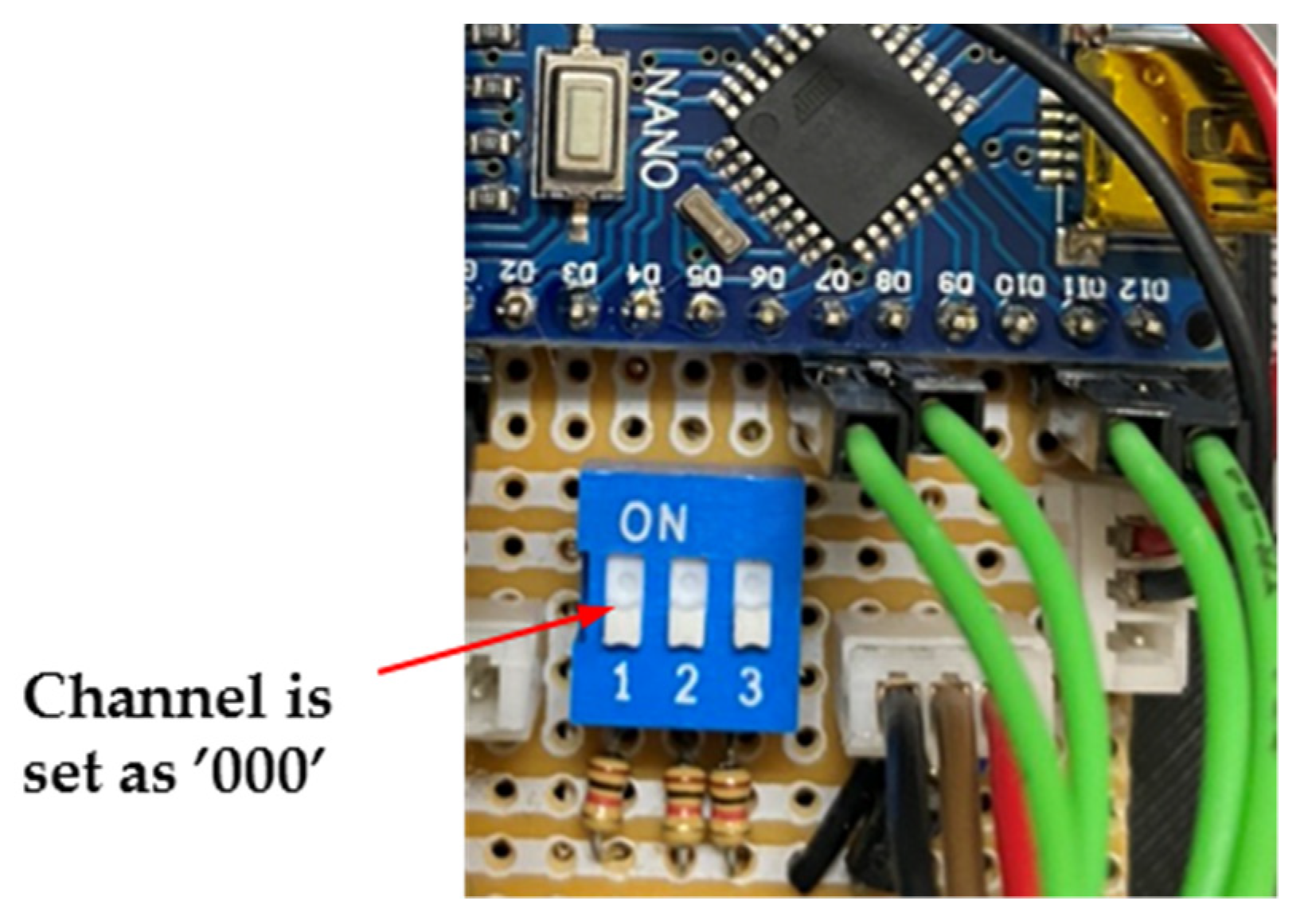
3.3. Hardware Implementation of the Proposed System

Figure 6 shows a hardware block diagram of the proposed IoT-based intelligent LED light. The power supply module adopts 110/220 V universal voltage. The central processing unit (MCU) [36] executes according to the parameter value sent by the communication module. Moreover, the MCU sends a control command to the LED brightness control module to determine the power ratio and intensity of the LED high-/low-light duration. The communication module is a Wi-Fi 2.4 GHz wireless transmission module responsible for data transmission with the cloud and transmission between the proposed IoT-based intelligent LED lights.
The communication module in Figure 6 is a Wi-Fi module, and its data transmission methods can generally be divided into two types: message-queuing telemetry transport (MQTT) and the HyperText transfer protocol (HTTP). We use the MQTT architecture. This is because compared to the HTTP architecture, MQTT architecture is in transmission and can reduce power consumption. In addition, the MCU of the IoT LED in Figure 6 will be responsible for uploading the collected data to the cloud. The current data are the trigger time of the personnel, the number of people passing by each hour, etc. These data can be used in future strategies, and more can be added in the future, such as for detecting smoke, CO2, PM2.5, etc., and other sensors to make the IoT LED more powerful. In addition, with the parameters uploaded to the cloud via the web, such as field F, high-light mode power WH, low-light mode power WL, and high-light duration T, the IoT LED will actively receive and store these parameters.
The communication transmission we adopt in this article is based on the MQTT architecture [31,34]. Hence, the proposed system can synchronize the time with the central server every minute, avoiding related problems caused by mistimed synchronization and data delay, described as follows:
  • The finite element machine architecture is used to write programs, so the proposed IoT-based intelligent LED light will automatically ignore it to avoid errors when false data injection happens.
  • A timestamp scheme is used as the data recognition judgment, so the same timestamp will only recognize one piece of data, and the data with errors due to delay will be ignored.
  • The solution to the first two problems can prevent system resources from being exhausted due to several applications.
An example of the preset values and settable ranges of the proposed IoT-based intelligent LED light parameters can be seen in Table 4. In this work, the parameters set include field F, high-light mode power WH, low-light mode power WL, and high-light duration T. These parameters are set to preset (default) values at the factory. Users can access the proposed IoT-based intelligent LED light via the internet to modify it. The setting range is shown in Table 1. The modified parameter values will also be uploaded to the cloud through the Wi-Fi 2.4 GHz wireless transmission module for big data analysis, which can set parameters for valuable suggestions in the future. The prototype of the proposed IoT-based intelligent LED light is demonstrated in Figure 7.
The LED brightness control module controls the brightness percentage of the high-light and low-light modes. It adjusts the output power of the high-light and low-light modes through pulse-width modulation (PWM) and then changes its brightness. For example, in Table 4, the setting range of the power WH in the high-light mode is 60–100%, and the setting range of the power WL in the low-light mode is 10–50%.
When no one is passing by, the proposed IoT-based intelligent LED lights in the same zone will operate in “low-light mode” simultaneously. When any one of the proposed IoT-based intelligent LED lights in this zone detects a person passing by (as shown in Figure 8), the wireless transmission module transmits the message to other IoT-based intelligent LED lights in the same zone and adjusts the brightness to the “high-light mode”; at the same time, instead of sequentially lighting up the proposed IoT-based intelligent LED lights.
The communication module in Figure 7 adopts a Wi-Fi 2.4 GHz wireless transmission module. This module manages the data transmission to the cloud and transmits signals among the proposed IoT-based intelligent LED lights. The transmission method between the proposed IoT-based intelligent LED lights is only the proposed IoT-based intelligent LED lights set to the same channel and will be sent or received from the other proposed IoT-based intelligent LED lights. For example, we suppose the proposed Master IoT-based intelligent LED light channel in Figure 9 is set to “000” (dip switch is set to “000”). In this case, the set parameters transmit to other channels and put them to “000” for the proposed slave IoT-based intelligent LED lights via wireless communication. As for the proposed IoT-based intelligent LED lights of different channels, this message will not be received. Please note that the MAC address is not used to facilitate the user in setting the area number arbitrarily because it is more convenient and direct to select the channel via a DIP switch. Using DIP switches instead of MAC addresses for group planning is to facilitate responses to future equipment failures. Field maintenance personnel can quickly replace faulty equipment by setting the same DIP-switch channel to reduce the chance of technicians coming to the scene. If the MAC address is used for group planning, IT staff should be asked to add and delete related MAC address groups every time the faulty device is replaced.
Therefore, the adopted DIP-switch method is more user-friendly and in line with actual usage. Moreover, when installing an extensive new parking lot lighting system, LED lights are vast. We suppose the group planning is carried out by the MAC address method at the bottom layer. In that case, the staff must enter the system to set the MAC address group to distinguish which LEDs belong to that group, but when the DIP switch is used to set the group in the field, the grouping speed will be much faster, thus the reason for adopting a DIP-switch-based scheme for setting the group in the zones.
This is a function designed for a large field. Because of a large zone, hundreds of proposed IoT-based intelligent LED lights may need to be set. It is a vast project to establish such a large number of the proposed IoT-based intelligent LED lights so that the channel values can be the same. The proposed IoT-based intelligent LED lights can be set to the same parameter value simultaneously and save effort and time. For example, using the large parking lot in Figure 2, we can set the channel of all proposed IoT-based intelligent LED lights in zone 1 to “001”, all proposed IoT-based intelligent LED lights in zone 2 to “002”, and all proposed IoT-based intelligent LED lights in zone 3 to “003”, etc. Hence, we can easily set a large number of the proposed IoT-based intelligent LED lights. The various parameters can be set through the DIP switch of the control circuit in the proposed IoT-based intelligent LED light. Furthermore, we can also set up related parameters via our developed mobile app, as shown in Figure 10. The adopted electronic components and their specifications for the proposed IoT-based intelligent LED light are arranged and listed in Table 5.

3.4. Energy Consumption Calculation

The proposed IoT-based intelligent LED light is divided into a high-light mode and a low-light mode. Therefore, it is more complicated to calculate the power consumption, unlike ordinary non-inductive LED lights. The factors that affect the power consumption include high-light mode power WH, low-light mode power WL, high-light duration T, the frequency of people and vehicles passing, whether there is continuous triggering, and so on.
To facilitate the derivation of the formula, we refer to the calculation method of power consumption in [1,35]. It is assumed that pedestrians and vehicles will not stay for too long when they pass by and pass by after T seconds, which means there is no continuous trigger. In this case, the elapsed time of people and vehicles is average and scattered (because it is uneven, the total power is the same as long as there is no continuous trigger).
Below, in addition to calculating the electric energy consumed by each proposed LED light per hour, we also calculated the electric power consumed by each proposed LED light in a year. We compared traditional non-inductive LED lights for the amount of energy saved, the cost savings, and the reduced carbon emissions to calculate its energy-saving rate (ESR). Finally, we use a parking lot as an example to calculate the total cost savings of the entire parking lot.
We illustrate how to calculate each proposed LED’s light energy consumed per hour according to the power changes in the high-light mode and the low-light mode, as shown in Figure 11. P(t) is used to describe the power change between the high-light mode and the low-light mode. Other parameters are described, as can be seen in Table 6.
Because of the previous assumption that “pedestrian’s elapsed time is average and scattered”, the elapsed time length of each person is 3600/f (f > 0). For the first pedestrian, 0~T seconds is the high-light mode, and T~3600/f second is the low-light mode, so we can calculate the electric energy Eph consumed by a proposed IoT-based intelligent LED light per hour by calculating the area:
if f = 0
E ph = ( 0 3600 P ( t ) d t )   J = ( 0 3600 W L d t )   J = ( 0 3600 W L d t ) / 3.6   ×   10 6   kW   h
If f > 0
E ph = f × ( 0 T P ( t ) d t + T 3600 / f P ( t ) d t )   J = f   ×   ( 0 T W H d t + T 3600 / f W L d t )   J = f   ×   ( 0 T W H d t + T 3600 / f W L d t ) / 3.6   ×   10 6   kW h
In addition, we assume that the lights in the parking lot are turned on 24 h a day, and a total of 365 × 24 = 8760 h are turned on in a year. Therefore, the annual electric energy Epy consumed by the proposed IoT-based intelligent LED light is:
E py =   E ph = E ph   ×   8760   kW   h
Compared with the general non-inductive lamp: 15 W T8 LED tube (only 15 W in full light mode), the electric energy consumed by each lamp per year is (15 W/1000) × 8760 = 131.4 kW⋅h, we can calculate if the general non-induction lamp 15 W T8 LED tube is changed to the proposed IoT-based intelligent light (new induction lamp), its energy-saving rate ESR, the amount of electricity saved per lamp per year Dpy, and the annual saving cost Mpy (assuming 4 TWD per kilowatt-hour of electricity), the carbon emission reduction Cpy in a year, etc. are calculated as follows (each kilowatt hour (kW⋅h) can generate 0.623 kgCO2e carbon emissions:
ESR = (15 − Eph)/15 ∗ 100%
Dpy = 131.4 − Eph ∗ 8760 kW h
Mpy = (131.4 − Eph ∗ 8760) kW·h ∗ 4 TWD/kW h
Cpy = (131.4 − Eph ∗ 8760) kW·h ∗ 0.623 kgCO2e/kW h

4. Experimental Results Analysis and Discussion

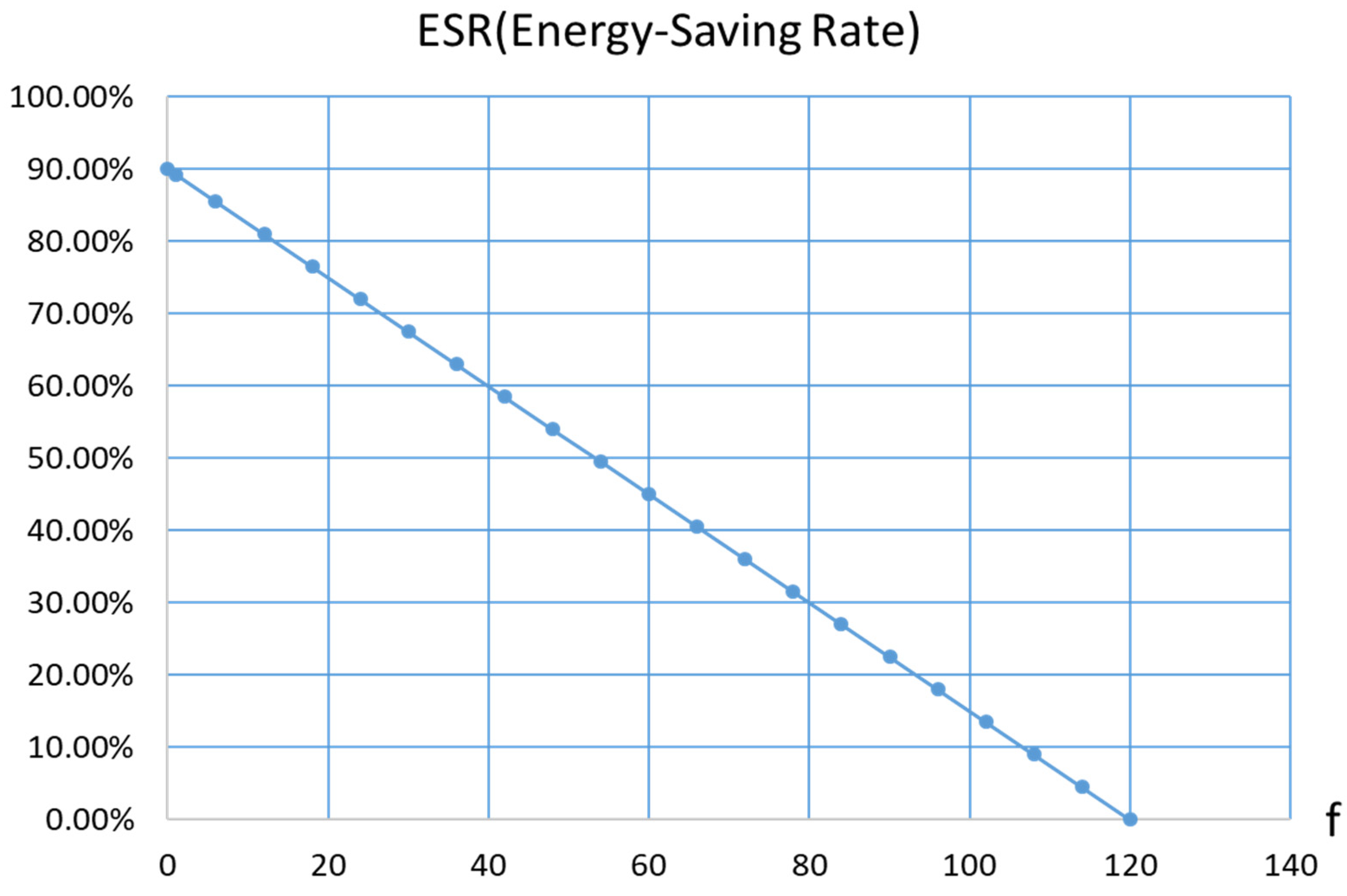
4.1. Energy Saving Rate (ESR) Calculation

As there is a close relationship between the ESR of the proposed IoT-based intelligent LED light and the number of activations of the high-light mode per hour f, this subsection will discuss the ESR and the number of triggers of the high-light mode per hour f, the relationship between this two, and calculate the maximum and minimum ESR.
First, from Equation (4), it can be established that there is an inverse correlation between ESR and the Eph of electric energy consumed by each proposed IoT-based intelligent LED light per hour. Equations (1) and (2), demonstrate that Eph is directly proportional to the number of activations of the hourly high-light mode f. Hence, it can be seen that the ESR is inversely proportional to the number of triggers of the high-light mode per hour f.
Next, we discuss the range of frequency the high-light mode is triggered per hour f. The minimum value is 0, indicating that no one passes by within an hour, and the maximum value is 3600/T, which means that every time someone passes by is T seconds. Someone passes by again immediately, without interruption (that is, within one hour, the high-light mode is from beginning to end), so the range of f is 0 ≤ f ≤ 3600/T. The default value of T for this work is 30 s, so 0 ≤ f ≤ 120.
We replace different f-values into the Eph equation to calculate the values of Epy, ESR, Dpy, Mpy, and Cpy, compared with the general non-inductive lamp 15 W T8 LED tube, as shown in Table 7. Due to limited space, only the essential parts are listed (f-value interval six printed out).
Table 7 indicates that 90.00% of the maximum ESR occurs when f = 0 (indicating that no one passes by within 1 h). The same is true for other Dpy, Mpy, and Cpy values. The ESR increases as the T value increases. With a linear decline, when f = 120 (means that people continuously pass by within 1 h), the ESR drops to 0%, but this is unlikely to happen because induction lights are usually installed in places where fewer people pass by. Figure 12 shows a graph of the relationship between the ESR and f-value.
Figure 13 shows the measured hourly (H) ESR change chart of a parking lot. After recording the actual number of people per hour and referring to Table 4, we can obtain the ESR for that hour and draw the daily ESR change chart. Taking the first hour of Monday as an example, with f = 1, after referring to Table 5, we can see that the ESR is 89.25%. Some results from Figure 13a–h can be observed as follows:
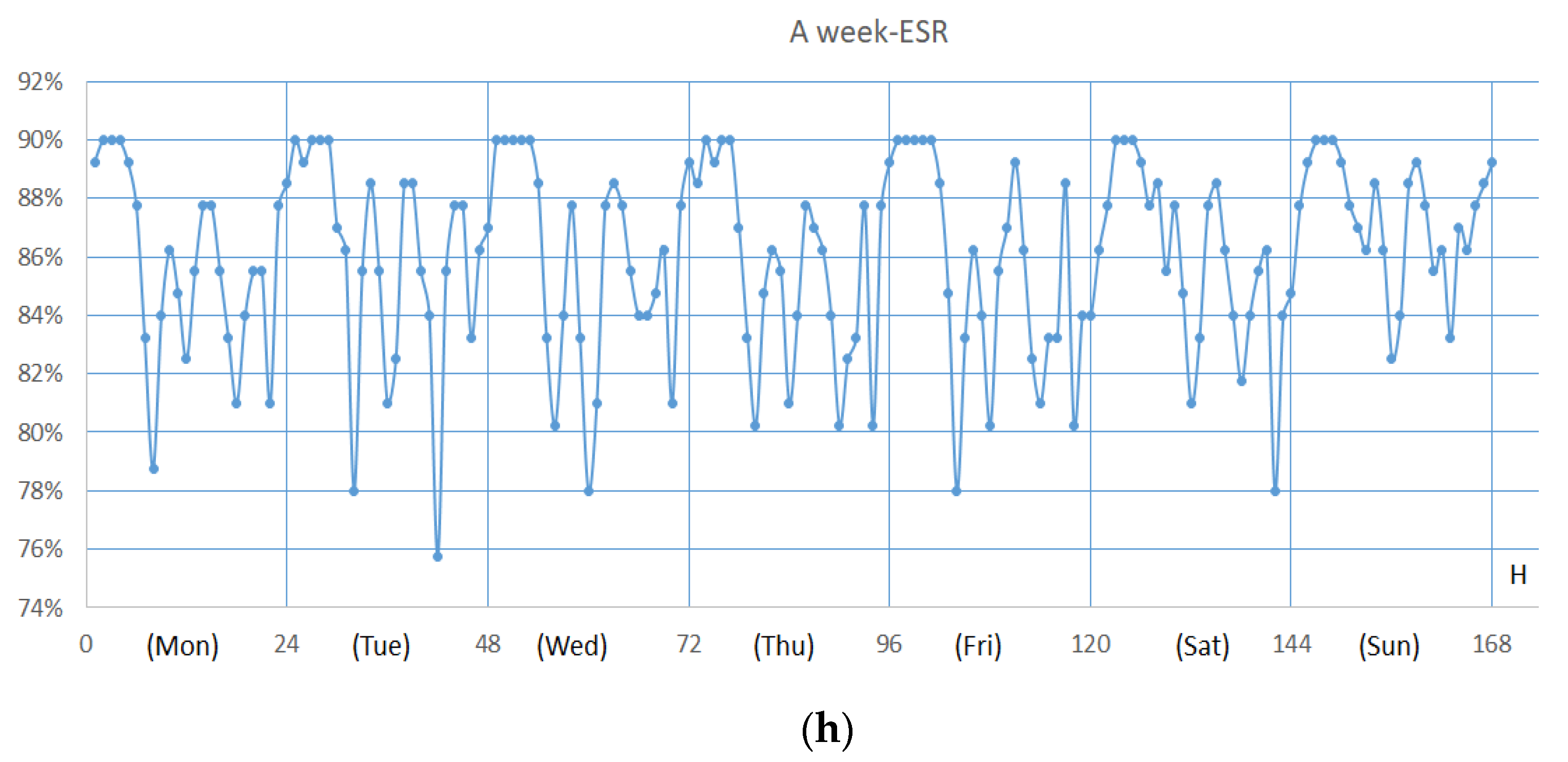
  • Most of the f-values at 0–5 o’clock every day are close to 0, so the ESR is very close to 90%, but Saturdays and Sundays are exceptions. A possible reason for this is that people are relatively late to bed because there are usually parties on weekends due to other events.
  • Most daily commuting hours or the noon hour have a high f-value, so the ESR is close to 80%, but typically people are not working on Saturdays and Sundays. Only noontime is more frequent, and the ESR value is around 80%.
  • This community’s daily garbage disposal time is 22:00, so the f-value is high at 22:00 every day, and the ESR value is low, except on Sundays, because the community does not collect garbage on Sundays.

4.2. Case Study for ESR Calculation

The energy-saving analysis was conducted by taking one parking lot as a demonstration. We assume that the parking lot is divided into 16 zones. Each zone has 16 LED lights for a total of 256 LED lights. Assuming that all are changed to the proposed IoT-based intelligent LED lights, we use the reduction in electricity consumption over the same period of the year to illustrates its energy-saving effects and expected results. The proposed system can set the parameter settings of each proposed IoT-based intelligent LED light in the parking lot via the Wi-Fi 2.4 GHz wireless transmission module without wasting human resources.
We use 265 lights to estimate the reduction in electricity consumption over the same period of the year. Still, to calculate electricity consumption more accurately, we assume that 12 people pass through each light hour (approximately one person passes) for 5 min, which is more average. We can directly refer to Table 3 to calculate (directly take the Epy, Dpy, Mpy, and Cpy values of f = 12), as follows:
  • The power consumption of 256 lights of this work in one year (Epy value of f = 12 is 24.966): 24.966 ∗ 256 = 6391.296 kW h.
  • 15 W T8 LED tube (non-inductive light, only 15 W in full light mode): 15 ∗ 24 ∗ 365 ∗ 256 = 33,638,400 W h = 33,638.4 kW h.
  • Reduced power consumption per year for 256 lights (Dpy value of f = 12 is 106.434): 106.434 ∗ 256 = 27,247.104 kW h.
  • Reduced cost of 256 lights in one year (Mpy value of f = 12 is 425.736): 425.736 ∗ 256 = 108,988.416 TWD.
  • Carbon emissions reduced by 256 lights in one year (Cpy value of f = 12 is 66.308): 66.308 ∗ 256 = 16,974.848 kgCO2e.
Therefore, as long as we change all 16 zones of the parking lot (each zone has 16 LED lights) to the proposed IoT-based intelligent LED lights, we can obtain the following expected results (assuming that there are 24 h a day, 12 people pass by every hour, and every degree is 4 TWD (Yuan)). Please note that the above calculation is only for the LED light part, and the part of the control circuit is omitted. Reduced electricity consumption, cost, and carbon emissions of the parking lot during the same year by using the proposed system are shown in Table 8. Finally, the ESR achieves 81% energy efficiency, saves 180,998.416 TWD/year, and reduces CO2 emissions by about 16,974.848 kgCO2e.
As a result, if the area is reduced to a 100 square meter parking lot, the illuminance standard of a general parking lot is about 100–200 LUX. According to actual measurement, installing an LED tube every 2.5 m can meet this requirement, so a 100 square meter parking lot is approximately (10/2.5) ∗ (10/2.5) =16 LED lights are needed to illuminate. When converted in Table 8, the annual electricity bill can be saved by 108,988.416/16 = CNY 6811.776 (the same is assuming 24 h a day, every hour 12 people are passing by and 4 TWD per degree).

5. Conclusions

In this article, a low-cost easy-to-install Master-Slave intelligent LED light-controlling system has been proposed, which is based on Internet of Things (IoT) techniques. The proposed system has been adopted and installed so the LED lights’ brightness in the same zone can be changed simultaneously to save energy consumption. Moreover, the parameters of the LED lights can be directly set. Furthermore, the related collected data can be uploaded to the cloud platform. In this article, we have used a parking lot as a case study. Experimental results showed that when the proposed system is installed in a zone with few people, the energy-saving rate will be as high as 90%. Moreover, when 12 people pass by the zone within one hour, its energy-saving rate can reach up to 81%.
Therefore, for large-scale fields, the proposed system can also directly set the parameters of LED lights via Wi-Fi 2.4 G Hz wireless transmission modules to uniformly set each LED light in the large-scale field parameter setting. Therefore, the proposed system is not only suitable for small families (as long as the lamp is replaced with the proposed IoT-based intelligent LED light), but it is suitable for large-scale public zones such as buildings, communities, factories, warehouses, etc., where people and vehicles pass by for a short time, and even general street lighting is also a very suitable target that could adopt the proposed system.
As a result, the detailed calculations have been demonstrated in the case study for ESR calculation section. In a parking lot with 16 areas (each area has 16 LED lights), if 12 people pass by each hour and each degree is priced at CNY 4 (yuan), it will be available every year. It saves CNY 108,988.416 and reduces the CO2 emissions of 16,974.848 kg. What’s more amazing is that its energy-saving rate is as high as 81%.
The most suitable area for the work is where people and vehicles will pass by for a short time. If it is used in an office, it is not practical. In the future, we will strengthen and improve this work to be used in office environments (places where people stay for a long time). The current preliminary idea is to combine the help of counters to distinguish whether there are people in the space correctly.
Finally, the advantages and contributions of this work compared to other systems are summarized, as follows.
  • We have improved the traditional sensor lights with motion sensors of low- and high-light modes. LED lights in the same zone will simultaneously change to the high-light mode instead of sequentially lighting up each LED.
  • The proposed system can retain the original lamp holder without wiring and setting up a server. It can achieve the energy-saving purpose of an intelligent LED light-controlling system.
  • The parameters of the LED lights can be set directly via the IoT, and the collected data can also be uploaded to the cloud.
  • The proposed system has a high power-saving rate. If the proposed system is installed where few people pass by, the energy-saving rate will be as high as 90%. When 12 people pass by every hour, the energy-saving rate is 81%.

Author Contributions

Conceptualization, C.-T.L. and H.-M.C.; methodology, C.-T.L. and L.-B.C.; software, C.-T.L. and L.-B.C.; validation, C.-T.L., C.-J.H., and W.-C.L.; formal analysis, C.-T.L. and C.-J.H.; investigation, C.-T.L. and L.-B.C.; resources, C.-T.L. and W.-C.L.; data curation, C.-T.L.; writing—original draft preparation, C.-T.L. and L.-B.C.; writing—review and editing, C.-T.L. and L.-B.C.; visualization, C.-T.L.; supervision, L.-B.C.; project administration, C.-T.L.; funding acquisition, L.-B.C. All authors have read and agreed to the published version of the manuscript.

Funding

This research was funded in part by the Ministry of Science and Technology (MoST), Taiwan, grant number MOST 109-2222-E-346-001. This work was also supported by the Ministry of Education (MoE), Taiwan, grant number MoE-110G0008.

Institutional Review Board Statement

Not applicable.

Informed Consent Statement

Not applicable.

Data Availability Statement

Not applicable.

Conflicts of Interest

The authors declare no conflict of interest.

References

  1. Lee, C.-T.; Ho, P.-T. Energy-saving research on new type of LED sensor lamp with low-light mode. Electronics 2020, 9, 1649. [Google Scholar] [CrossRef]
  2. Lee, C.-T.; Ho, P.-T.; Lee, Y.-Y.; Chen, L.-B. A research on the 4th generation intelligent energy-saving solar water heating tank. Electronics 2020, 9, 1941. [Google Scholar] [CrossRef]
  3. Karanchery, S.; Rakesh, N. Smart power socket using Internet of Things. In Proceedings of the 2020 International Conference 510 on Inventive Computation Technologies (ICICT), Coimbatore, India, 26–28 February 2020; pp. 1060–1064. [Google Scholar]
  4. Li, D.H.W.; Cheung, K.L.; Wong, S.L.; Lam, T.N.T. An analysis of energy-effcient light fittings and lighting controls. Appl. Energy 2010, 87, 558. [Google Scholar] [CrossRef]
  5. Tan, Y.K.; Huynh, P.T.; Wang, Z. Smart personal sensor network control for energy saving in DC grid powered LED lighting system. IEEE Trans. Smart Grid 2013, 4, 669–676. [Google Scholar] [CrossRef]
  6. Dascalaki, E.G.; Droutsa, K.; Gaglia, A.G.; Kontoyiannidis, S.; Balaras, C.A. Data collection and analysis of the building stock and its energy performance—An example for Hellenic buildings. Energy Build. 2010, 42, 1231–1237. [Google Scholar] [CrossRef]
  7. Ozcelik, M.A. Light sensor control for energy saving in DC grid smart LED lighting system based on PV system. J. Optoelectron. Adv. Mater. 2016, 18, 468–474. [Google Scholar]
  8. Farsakoglu, O.F.; Atik, I. Analysis of the factors affecting operation and efficiency of power LED drivers and circuit design. Optoelectron. Adv. Mater. 2015, 9, 1356–1361. [Google Scholar]
  9. Chiu, J.H.; Lo, Y.K.; Chen, J.T.; Cheng, S.J.; Chung, Y.L.; Mou, S.C. A high-efficiency dimmable LED driver for low-power lighting applications. IEEE Trans. Ind. Electron. 2010, 57, 735–743. [Google Scholar] [CrossRef]
  10. Manuel, A.; Lamar, D.G.; Sebastian, J.; Balacco, D.; Aguissa, D.; Manuel, A.; Lamar, D.G.; Sebastian, J.; Balacco, D.; Aguissa, D. High-efficiency LED driver without electrolytic capacitor for street lighting. IEEE Trans. Ind. Appl. 2013, 49, 127–137. [Google Scholar]
  11. Li, S.; Chen, H.; Tan, S.C.; Hui, S.Y.; Waffenschmidt, E. Power flow analysis and critical design issues of retrofit light-emitting diode (LED) light bulb. IEEE Trans. Power Electron. 2015, 30, 3830–3840. [Google Scholar] [CrossRef] [Green Version]
  12. Bureau of Energy, MOEA. New Century Power-Saving Environmental Lighting. Available online: https://energymagazine.itri.org.tw/Cont.aspx?CatID=30&ContID=542 (accessed on 20 May 2019).
  13. LEDinside. T2020 Global LED Home Smart Lighting Market Outlook. 2020. Available online: https://m.ledinside.com.tw/node/view/36565.html (accessed on 17 May 2021).
  14. Caicedo, D.; Pandharipande, A. Distributed illumination control with local sensing and actuation in networked lighting systems. IEEE Sens. J. 2013, 13, 1092–1104. [Google Scholar] [CrossRef] [Green Version]
  15. Matta, S.; Mahmud, S.M. An intelligent light control system for power saving. In Proceedings of the 36th Annual Conference on IEEE Industrial Electronics Society (IECON), Glendale, AZ, USA, 7–10 November 2010; pp. 3316–3321. [Google Scholar]
  16. Lu, J.; Birru, D.; Whitehouse, K. Using simple light sensors to achieve smart daylight harvesting. In Proceedings of the 2nd ACM Workshop Embedded Sensing Systems for Energy-Efficiency Building, Zürich, Switzerland, 2–5 November 2010; pp. 73–78. [Google Scholar]
  17. Erol-Kantarci, M.; Mouftah, H.T. Wireless sensor networks for cost-efficient residential energy management in the smart grid. IEEE Trans. Smart Grid 2011, 2, 314–325. [Google Scholar] [CrossRef]
  18. Bai, Y.-W.; Ku, Y.-T. Automatic room light intensity detection and control using a microprocessor and light sensors. In Proceedings of the 2008 IEEE International Symposium on Consumer Electronics (ISCE), Vilamoura, Portugal, 14–16 April 2008; pp. 1–4. [Google Scholar] [CrossRef] [Green Version]
  19. Tang, S.J.W.; Kalavally, V.; Ng, K.Y.; Tan, C.P.; Parkkinen, J. Real-time closed-loop color control of a multi-channel luminaire using sensors onboard a mobile device. IEEE Access 2018, 6, 54751–54759. [Google Scholar] [CrossRef]
  20. Elejoste, P.; Angulo, I.; Perallos, A.; Chertudi, A.; Zuazola, I.J.G.; Moreno, A.; Azpilicueta, L.; Astrain, J.J.; Falcone, F.; Villadangos, J. An easy to deploy street light control system based on wireless communication and LED technology. Sensors 2013, 13, 6492–6523. [Google Scholar] [CrossRef]
  21. Byun, J.; Shin, T. Design and implementation of an energy-saving lighting control system considering user satisfaction. IEEE Trans. Consum. Electron. 2018, 64, 61–68. [Google Scholar] [CrossRef]
  22. Perkasa, R.; Wahyuni, R.; Melyanti, R.; Irawan, Y. Light control using human body temperature based on Arduino Uno and PIR (Passive Infrared Receiver) sensor. J. Robot. Control 2021, 2, 307–310. [Google Scholar] [CrossRef]
  23. Lestari, U.; Fatkhiyah, E.; Prakoso, A.F. Application of home light control system using Arduino with mobile based Wifi media. Int. J. Inf. Syst. Comput. Sci. 2019, 2, 67–75. [Google Scholar]
  24. Wahyuni, R.; Irawan, Y. Web-based employee performance assessment system in PT. Wifiku Indonesia. J. Appl. Eng. Technol. Sci. 2020, 1, 60–69. [Google Scholar] [CrossRef]
  25. Mohamed, R.R.; Mohamed, M.A.; Azmi, K.; Rao, E.; Hashim, W. Indoor smart lighting controlling using human detection. Int. J. Adv. Trends Comput. Sci. Eng. 2020, 9, 566–570. [Google Scholar]
  26. Byun, J.; Hong, I.; Lee, B.; Park. S. Intelligent household LED lighting system considering energy efficiency and user satisfaction. IEEE Trans. Consum. Electron. 2013, 59, 70–76. [Google Scholar] [CrossRef]
  27. Bellido-Outeirino, F.J.; Flores-Arias, J.M.; Domingo-Perez, F.; Gil-de-Castro, A.; Moreno-Munoz, A. Building lighting automation through the integration of DALI with wireless sensor networks. IEEE Trans. Consum. Electron. 2012, 58, 47–52. [Google Scholar] [CrossRef]
  28. Pan, M.-S.; Yeh, L.-W.; Chen, Y.-A.; Lin, Y.-H.; Tseng, Y.-C. A WSN-based intelligent light control system considering user activities and profiles. IEEE Sens. J. 2008, 8, 1710–1721. [Google Scholar] [CrossRef]
  29. Pandharipande, A.; Caicedo, D. Daylight integrated illumination control of LED systems based on enhanced presence sensing. Energy Build. 2011, 43, 944–950. [Google Scholar] [CrossRef]
  30. Park, T.-J.; Hong, S.-H. Experimental case study of a BACnet-based lighting control system. IEEE Trans. Autom. Sci. Eng. 2009, 6, 322–333. [Google Scholar] [CrossRef]
  31. Uhm, Y.; Hong, I.; Kim, G.; Lee, B.; Park, S. Design and implementation of power-aware LED light enabler with location-aware adaptive middleware and context-aware user pattern. IEEE Trans. Consum. Electron. 2010, 56, 231–239. [Google Scholar] [CrossRef]
  32. Zhang, J.; Kim, H.-J. Design of smart LED lighting switch with learning user’s light controlling pattern. In Proceedings of the 2011 International Conference on ICT Convergence (ICTC), Seoul, Korea, 28–30 September 2011; pp. 656–657. [Google Scholar]
  33. Bhardwaj, S.; Ozcelebi, T.; Verhoeven, R.; Lukkien, J. Smart indoor solid state lighting based on a novel illumination model and implementation. IEEE Trans. Consum. Electron. 2011, 57, 1612–1621. [Google Scholar] [CrossRef]
  34. Cho, Y.S.; Kwon, J.; Choi, S.; Park, D.-H. Development of smart LED lighting system using multi-sensor module and Bluetooth low energy technology. In Proceedings of the 2014 Eleventh Annual IEEE International Conference on Sensing, Communication, and Networking (SECON), Singapore, 30 June–3 July 2014; pp. 191–193. [Google Scholar]
  35. Chu, H.-M.; Lee, C.-T.; Chen, L.-B.; Lee, Y.-Y. An expandable modular Internet of Things (IoT)-based temperature control power extender. Electronics 2021, 10, 565. [Google Scholar] [CrossRef]
  36. Chen, L.-B.; Chen, Y.-L.; Huang, I.-J. A real-time power analysis platform for power-aware embedded system development. J. Inf. Sci. Eng. 2011, 27, 1165–1182. [Google Scholar]
  37. Lin, Y.-B.; Huang, C.-M.; Chen, L.-K.; Sung, G.-N.; Yang, C.-C. MorSocket: An expandable IoT-based smart socket system. IEEE Access 2018, 6, 53123–53132. [Google Scholar] [CrossRef]
  38. Velinov, A.; Mileva, A.; Wendzel, S.; Mazurczyk, W. Covert channels in the MQTT-based Internet of Things. IEEE Access 2019, 7, 161899–161915. [Google Scholar] [CrossRef]
  39. Phan, C.T.; Pham, D.D.; Tran, H.V.; Tran, T.V.; Huu, P.N. Applying the IoT platform and green wave theory to control intelligent traffic lights system for urban areas in Vietnam. KSII Trans. Internet Inf. Syst. 2019, 13, 34–52. [Google Scholar]
  40. Bouhedda, M.; Benyezza, H.; Toumi, Y.; Rebouh, S. Fuzzy Traffic Lights Controller Based on PLC. In Proceedings of the International Conference in Artificial Intelligence in Renewable Energetic Systems, Tipaza, Algeria, 22–24 December 2020; Springer: Berlin/Heidelberg, Germany, 2020; pp. 447–456. [Google Scholar]
  41. Albatish, I.M.; Abu-Naser, S.S. Modeling and controlling smart traffic light system using a rule based system. In Proceedings of the 2019 International Conference on Promising Electronic Technologies (ICPET), Gaza City, Palestine, 23–24 October 2019; IEEE: Piscataway, NJ, USA, 2019; pp. 55–60. [Google Scholar]
  42. Abohashima, H.; Gheith, M.; Eltawil, A. A proposed IoT based Smart traffic lights control system within a V2X framework. In Proceedings of the 2020 2nd Novel Intelligent and Leading Emerging Sciences Conference (NILES), Giza, Egypt, 24–26 October 2020; IEEE: Piscataway, NJ, USA, 2019; pp. 338–343. [Google Scholar]
  43. Caputo, D.; Verderame, L.; Ranieri, A.; Merlo, A.; Caviglione, L. Fine-hearing Google Home: Why silence will not protect your privacy. J. Wirel. Mob. Networks Ubiquitous Comput. Dependable Appl. 2020, 11, 35–53. [Google Scholar] [CrossRef]
  44. Kang, J.; Kim, J.; Sohn, M. Creative Design of a Humanized Home Lighting. J. Internet Serv. Inf. Security 2019, 9, 59–67. [Google Scholar] [CrossRef]
  45. Tian, Y. Creative Design of a Humanized Home Lighting. In Proceedings of the 2021 International Conference on Computer Technology and Media Convergence Design (CTMCD), Sanya, China, 23–25 April 2021; pp. 301–304. [Google Scholar] [CrossRef]
  46. Motlagh, N.H.; Khajavi, S.H.; Jaribion, A.; Holmstrom, J. An IoT-based automation system for older homes: A use case for lighting system. In Proceedings of the 2018 IEEE 11th Conference on Service-Oriented Computing and Applications (SOCA), Paris, France, 20–22 November 2018; pp. 1–6. [Google Scholar] [CrossRef]
  47. Forestiero, A.; Masrroianni, C.; Meo, M.; Papuzzo, G.; Sheikhalishahi, M. Hierarchical Approach for Green Workload Management in Distributed Data Centers. In Proceedings of the European Conference on Parallel Processing, Porto, Portugal, 25–29 August 2014; pp. 323–334. [Google Scholar]
  48. Philips Smart Light Bulbs. Available online: https://www.philips-hue.com/en-us/products/smart-light-bulbs (accessed on 2 December 2021).
Figure 1. A scenario where all the LED lights in zone 1 change to high-light mode at the same time.
Applsci 12 00420 g001
Figure 2. A new type of LED sensor light lamp (T8 LED light tube) [1].
Applsci 12 00420 g002
Figure 3. A scenario of the proposed system installed in a large parking lot.
Applsci 12 00420 g003
Figure 4. Flowchart of the system processes.
Applsci 12 00420 g004
Figure 5. System architecture (see Figure 6 for the hardware block diagram of IoT LED).
Applsci 12 00420 g005
Figure 6. Hardware block diagram of the proposed IoT-based intelligent LED light (IoT LED).
Applsci 12 00420 g006
Figure 7. The prototype of the proposed IoT-based intelligent LED light.
Applsci 12 00420 g007
Figure 8. Actual test of the proposed system.
Applsci 12 00420 g008
Figure 9. The proposed IoT-based intelligent LED light with channel set to “000”.
Applsci 12 00420 g009
Figure 10. Setting screen of our developed mobile device app for the proposed IoT-based intelligent LED light.
Applsci 12 00420 g010
Figure 11. Power changes in high-light mode and low-light mode.
Applsci 12 00420 g011
Figure 12. The relationship between ESR and f-value.
Applsci 12 00420 g012
Figure 13. The measured hourly (H) ESR change chart of a parking lot. (a) Monday; (b) Tuesday; (c) Wednesday; (d) Thursday; (e) Friday; (f) Saturday; (g) Sunday; (h) whole week.
Applsci 12 00420 g013aApplsci 12 00420 g013b
Table 1. A comparison of related works with the proposed system.
Related Work[15,16][18][19][20][22,23,24][25][31][1]This Work
ConnectionWiredWirelessWirelessWirelessWirelessWirelessWireless*Wireless
Sensors AdoptionLight sensorPIR sensorSmartphone cameraLight sensor, humidity sensor, and temperature sensorPIR sensor2 PIR sensorsPIR sensorPIR sensorPIR sensor
IoT-basedNoNoNoYesNoNoNoNoYes
Control MethodDirectDirectDirectDirectDirectDirectDirect**Master-Slave
Server/MCU-Based ControlServerMCUMCUServerMCUMCUServerNoMCU
Energy-savingMediumHighN/AMediumMediumMediumMediumHighHigh
Application FieldLarge fieldHomeHomeStreet lampsClassrooms or rooms HomeSmall/HomeLarge
Note: * Ref. [1] is a single device that has not been connected to other device designs. ** Ref. [1] has no control mechanism.
Table 2. A comparison of Philips hue smart lighting full-color situational 10 W bulb [48] with this work.
Related WorkPhilips Hue Smart Lighting BulbThis Work
Applicable FieldsPrivate areas such as living rooms or roomsPublic regions such as parking lots or corridors
PIR Sensor AdoptionNoYes
IoT-BasedYesYes
Power Consumption10 W14 W
DimmingFreely dimmableExecuting in low-light mode when no one is (brightness can be adjusted).
Situational LightingIt can be changed in full color according to the situation.No
Regional Chain ResponseNoLEDs in the same region can be brightened at the same time.
PriceNT$1900 (About US$67.9)NT$600 (About US$21.4)
Table 3. The difference comparison between this work and [1].
No.FeatureThis Work[1]
1Large-scale intelligent LED lighting systemIt can be easily implemented and installedIt can only be installed individually. Additional wiring and setting up a server can be completed without a connection function. Otherwise, it will only be similar to a general sensor light.
2Regional synchronization functionYesNo
3IoT-basedYesNo
4Timing controlProgrammable (flexible setting)RC charge/discharge (fixed)
5Control methodMaster-SlaveNo control mechanism
6Mobile device app.YesNo
7Application fieldLarge-scale fieldSmall-scale field
Table 4. An example of the preset values and settable ranges of the proposed IoT-based intelligent LED light parameters.
ParametersPreset ValueSettable Ranges
Field (F)Parking lotCorridorStairwellToilet1: Parking lot
2: Corridor
3: Stairwell
4: Toilet
5. User definition
High-light mode power (WH)100%100%100%100%60–100%
Low-light mode power (WL)10%20%20%40%10–50%
High-light duration (T)30 s20 s20 s120 s10–180 s
Table 5. The adopted electronic components and their specifications for the proposed IoT-based intelligent LED light.
No.NameDescription
1MCUArduino Nano MCU adopted
2Motion sensorMicrowave radar sensor switch module (human body detector sensor), RCWL-0516 adopted
3Communication module2.4 GHz Wi-Fi wireless communication module (NINA-W102 adopted)
4MiscellaneousMicro switch, DIP switch LEDs, wires, etc.
Table 6. Parameter descriptions.
ParameterDescription
TThe number of seconds that the high-light mode is maintained when someone passes by; the proposed IoT-based intelligent LED light defaults to 30 s
FThe number of pedestrians passing by per hour; that is, the frequency of the high-light mode being activated per hour
WHPower in high-light mode; the default power of the proposed IoT-based intelligent LED light is 15 W in high-light mode (default value is 100%)
WLThe power in low-light mode; the default power of the proposed IoT-based intelligent LED light is 1.5 W in low-light mode (default value is 10%)
Table 7. Eph, Epy, ESR, Dpy, Mpy, Cpy values of each proposed IoT-based intelligent LED light with different f values.
fEph (kW h)Epy (kW h)ESR (%)Dpy (kW h)Mpy (TWD)Cpy (kgCO2e)
00.001513.140090.00%118.2600473.04073.676
10.001614.125589.25%117.2745469.09873.062
60.002219.053085.50%112.3470449.38869.992
120.002924.966081.00%106.4340425.73666.308
180.003530.879076.50%100.5210402.08462.625
240.004236.792072.00%94.6080378.43258.941
300.004942.705067.50%88.6950354.78055.257
360.005648.618063.00%82.7820331.12851.573
420.006254.531058.50%76.8690307.47647.889
480.006960.444054.00%70.9560283.82444.206
540.007666.357049.50%65.0430260.17240.522
600.008372.270045.00%59.1300236.52036.838
660.008978.183040.50%53.2170212.86833.154
720.009684.096036.00%47.3040189.21629.470
780.010390.009031.50%41.3910165.56425.787
840.011095.922027.00%35.4780141.91222.103
900.0116101.835022.50%29.5650118.26018.419
960.0123107.748018.00%23.652094.60814.735
1020.0130113.661013.50%17.739070.95611.051
1080.0137119.57409.00%11.826047.3047.368
1140.0143125.48704.50%5.913023.6523.684
1200.0150131.40000.00%0.00000.0000.000
Table 8. Reduced electricity consumption, cost, and carbon emissions of a parking lot during the same year.
Electricity Consumption before Improvement
(Degrees/Year)
Electricity Consumption after Improvement
(Degrees/Year)
Power Saving
(Degrees/Year)
ESRElectricity Bills Savings
(Yuan/Year)
Reduced CO2
Emissions
(kgCO2e)
33,638.46391.29627,247.10481%108,988.41616,974.848
Publisher’s Note: MDPI stays neutral with regard to jurisdictional claims in published maps and institutional affiliations.

