
Research on Door Opening Operation of Mobile Robotic Arm Based on Reinforcement Learning

School of Electrical Engineering, Naval University of Engineering, Wuhan 430030, China
*
Author to whom correspondence should be addressed.
Appl. Sci. 2022, 12(10), 5204; https://0-doi-org.brum.beds.ac.uk/10.3390/app12105204
Submission received: 17 April 2022
/
Revised: 8 May 2022
/
Accepted: 13 May 2022
/
Published: 20 May 2022
(This article belongs to the Special Issue Applications of AI in Robotic Control Systems)
Abstract
:Featured Application
This work can be applied to grasping tasks based on vision-guided mobile robotic arm platforms, such as intelligent service robots, dangerous environment rescue, indoor equipment inspection, etc.
Abstract
The traditional robotic arm control method has strong dependence on the application scenario. To improve the reliability of the mobile robotic arm control when the scene is disturbed, this paper proposes a control method based on an improved proximal policy optimization algorithm. This study researches mobile robotic arms for opening doors. At first, the door handle position is obtained through an image-recognition method based on YOLOv5. Second, the simulation platform CoppeliaSim is used to realize the interaction between the robotic arm and the environment. Third, a control strategy based on a reward function is designed to train the robotic arm and applied to the opening-door task in the real environment. The experimental results show that the proposed method can accelerate the convergence of the training process. Besides, our method can effectively reduce the jitter of the robotic arm and improve the stability of control.
1. Introduction
In the field of modern industrial technology, robotic arms are used to perform dangerous and repetitive tasks. To expand the working range of the robotic arms, the researchers combined the robotic arm with the mobile platform to form a mobile robotic arm. The mobile robotic arm has the moving function of the mobile platform and the flexible operation function of the robotic arm. At present, the mobile robotic arm is widely used in the fields of life services, industrial manufacturing, and space exploration, and its research has important theoretical value and broad application prospects [1].
At present, the movement of the mobile robotic arm mainly adopts the method of vision guidance [2,3]. Sriram Emarose et al. [4] established a visual feedback loop between the mobile robotic arm and the target, and combined sonar and camera to estimate the distance between the mobile robotic arm and the target; the continuous tracking of the target was conducted for path planning. The ability to detect and localize specific objects in real time plays a vital role in realizing the grab-and-place tasks of the mobile robotic arm. Mohammed M. Ali et al. [5] used a Kinect sensor and color segmentation algorithm to detect and locate monochromatic objects. This study employs a feature detector with a brute force matcher [6] to detect features in template images and live video of the desired object. This method has great limitations and it is difficult to complete the task of target detection when the matching target in the original image rotates or changes in size.
The motion planning of mobile robotic arms is usually achieved by demonstration in traditional industrial applications. For application scenarios with changing working environments, traditional control methods are becoming increasingly challenging to meet the needs of users to control robotic arms quickly. Květoslav Belda et al. [7] proposed a model predictive control method for local motion control of a mobile robotic arm. Considering the complex tasks that the robotic arm needs to perform, the proposed solution represents a suitable energy-optimized centralized control. Woojin Chung et al. [8] proposed a control strategy for opening the door with a mobile robotic arm, which uses a comprehensive strategy of motion coordination to achieve the control of the robotic arms. Although most mobile robotic arms have modular and fully autonomous systems, the accuracy of the control of a mobile robotic arm will be disturbed when there are uncertain disturbances in the real environment. Arduengo et al. [9] designed an algorithm that fuses convolutional neural networks with efficient point cloud processing using a robust and adaptive Bayesian framework to estimate door handle poses in real time from images. Finn et al. [10] used the deep learning method to establish a deep prediction model of the mobile robotic arm body, trained the neural network based on the strategy search algorithm of predictive control, and applied it to the control of the robotic arm’s motion. To further improve the autonomous learning ability of mobile robotic arms, Ning Yang et al. [11] proposed a quantitative control method for wheeled mobile robotic arms for the problem of continuous-time uncertain Markov hopping systems with mixed time delay and transition probability. The method analyzes the Markov decision [12] process, balances the safety and efficiency of the mobile robotic arm, and provides guidance for the safe operation of the mobile robotic arm. Li Xing et al. [13] designed a policy search algorithm to realize the automatic learning of mobile robotic arms. A convolutional neural network control scheme is designed to maintain the robustness of the mobile robotic arm and avoid repetitive learning strategies. The emergence and development of deep reinforcement learning [14,15] methods have provided the possibility for robotic arms to complete operational tasks autonomously. Given the great potential of this method, deep reinforcement learning algorithms such as trust region policy optimization (TRPO) [16] and proximal policy optimization (PPO) [17] are used in robotic arm control. Kaveh Kamali et al. [18]. applied the PPO algorithm to model training; the information that can be obtained in the process of training is limited, which leads to low exploration efficiency of the robotic arm and the final learning effect has difficulty meeting the requirements.
In this paper, the recognition method of YOLOv5 [19] is used for visual guidance to quickly and accurately identify the door handle target. For the application of the deep reinforcement learning method in the control of the mobile robotic arm, the training convergence speed is slow and the stability is poor because of the sparse reward value of the algorithm. To reduce training time and help the algorithm converge, this paper proposes an improved PPO algorithm. It can learn complex behaviors, handle continuous action spaces, and find good policies in environments with high-dimensional state spaces. The research adopts the co-simulation method to realize the interaction between the mobile robotic arm and the virtual environment. It also applies the trained strategy to the door-opening task of the mobile robotic arm platform. The effectiveness of the method is verified by comparative experiments.
The contributions of this work are as follows:
- The method of YOLOV5 is applied to door-handle recognition, and the relationship between distance and pixel ratio is experimentally fitted for door-handle localization.
- The state space, action space and reward function are designed to realize the interaction between the robotic arm and the environment.
- An improved PPO algorithm is presented by expanding the experience pool to reduce the exploration of the useless environment.
- The comparison experiments show that the improved PPO algorithm is faster and more stable than the TRPO and PPO algorithms.
The rest of this paper is organized as follows. Section 2 describes the method of handle identification and positioning. Section 3 proposes the improved PPO algorithms. Section 4 establishes a simulation environment to test reinforcement learning algorithms such as TRPO, PPO, and improved PPO. In Section 5, the trained model is applied to the recognition and grasping task of the mobile robotic arm in the real scene. Section 6 concludes the paper and discusses the future work.
2. Handle Recognition and Positioning Method Description
In this section, the proposed identification and positioning methods are described. With the increasing demand for target detection accuracy and speed in practical applications, the current target detection algorithms mainly use detection methods based on deep learning. Target detection algorithms based on deep learning include Faster R-CNN [20], SSD [21], YOLOv3 [22], YOLOv5, etc. Compared with traditional detection methods, YOLOv5 has the characteristics of good robustness, strong generalization, and high precision.
The experiment realizes the real-time detection of the door handle by the YOLOv5 method. First, we capture multiple door-handle pictures through the camera. Besides, we annotate images with the Make Sense online tool to create a door handle dataset. Finally, the door-handle model is trained on the server and the trained model is applied to door-handle detection.
2.1. YOLOv5 Network Model
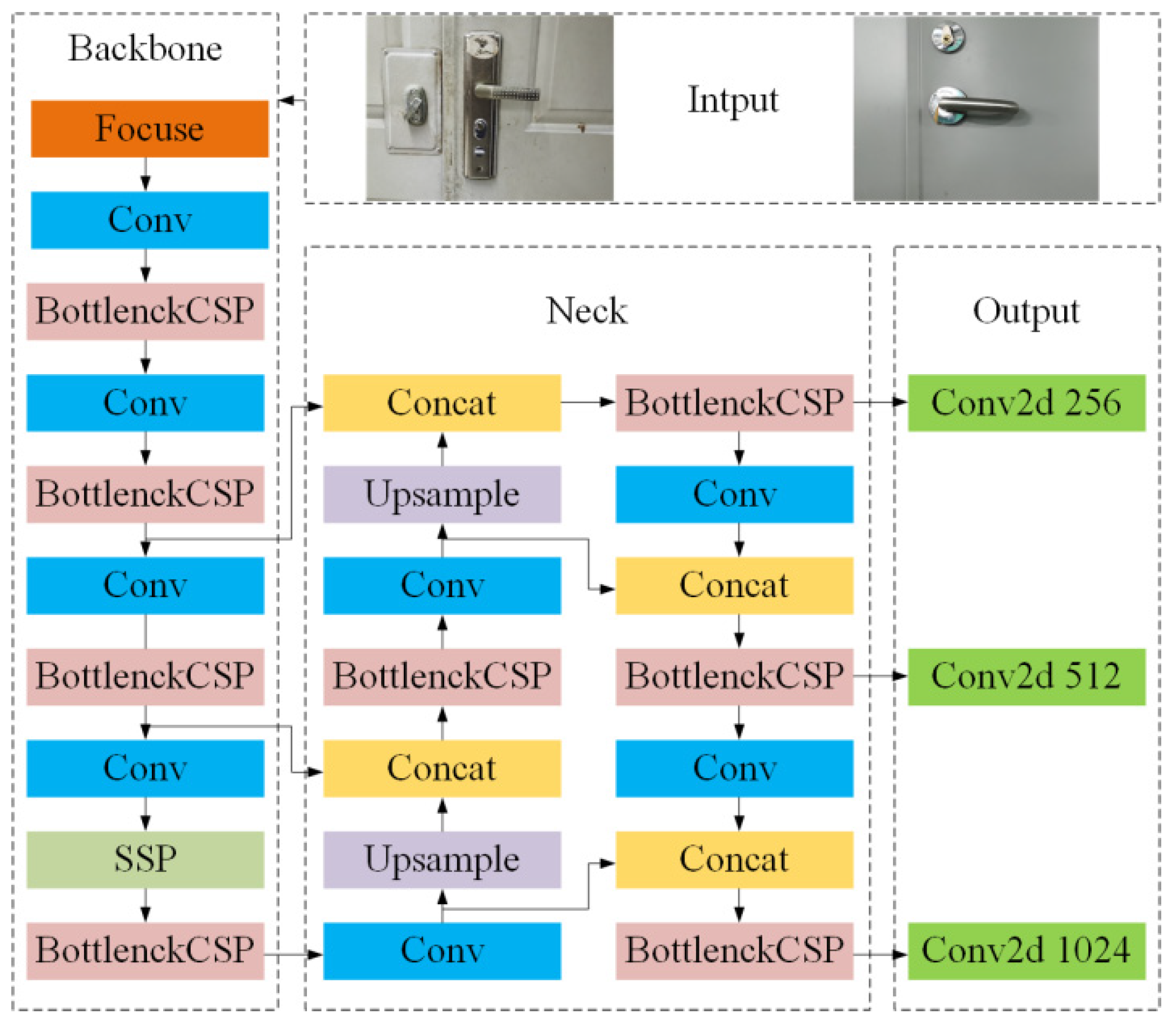
The YOLOv5 network structure consists of four parts: Input, Backbone, Neck, and Output layer. The network structure is shown in Figure 1.
The input terminal Input adopts a data-enhancement method to perform an adaptive scaling operation on the input image. The focus structure at the front end of Backbone effectively improves the quality of image extraction through convolution operations. The center and scale prediction (CSP) structure enhances the network’s ability to fuse features. The spatial pyramid pooling (SPP) module first uses kernels of varied sizes to perform max-pooling operations. Neck aggregates the feature information with the output features of the CSP module and fully integrates the image features of different layers. The output layer Output adopts the generalized intersection over union (GIOU) loss method to increase the measure of the intersection scale, which solves the situation that the two boxes do not intersect.
2.2. Handle Positioning
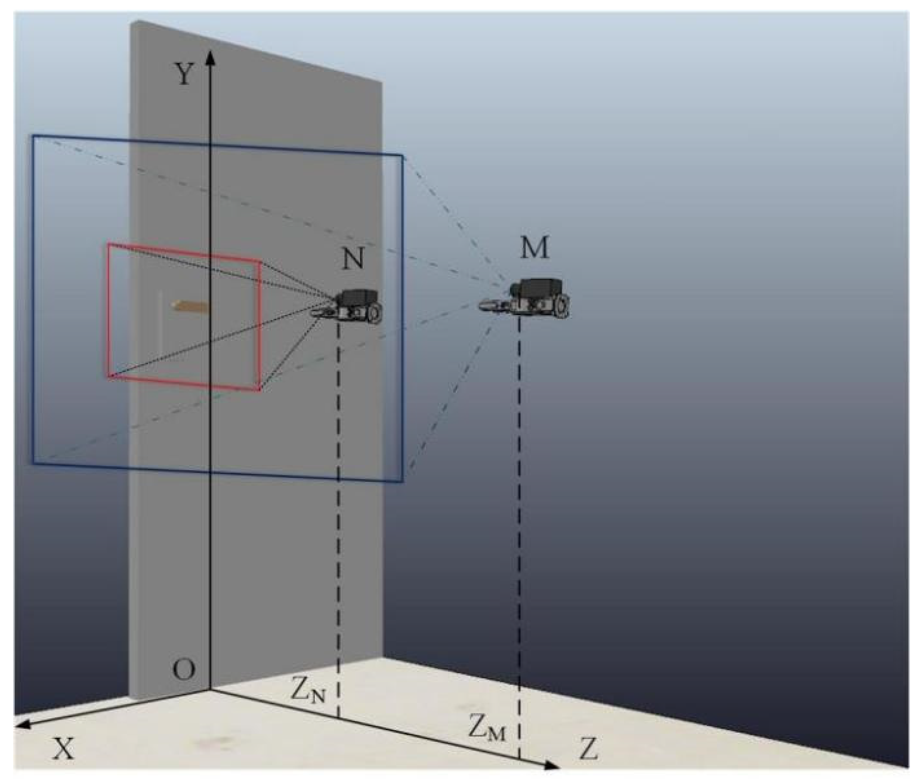
Move the robotic arm in front of the door and adjust the pose so that the camera is parallel to the door. This experiment aims to measure the vertical distance between the camera and the door plane and calculate the ratio of the recognition frame’s length to the picture’s length when the camera is constrained by a parallel plane. The relationship between the two is described by the fitting curve, and the fitting curve is substituted according to the length ratio. The formula calculates the vertical distance between the mobile robotic arm platform and the door plane.
As shown in Figure 2, the camera position varies from N to M; corresponding to the projection on the Z-axis ZN respectively ZM represents the vertical distance from the camera to the door plane—the trail of opening the door.
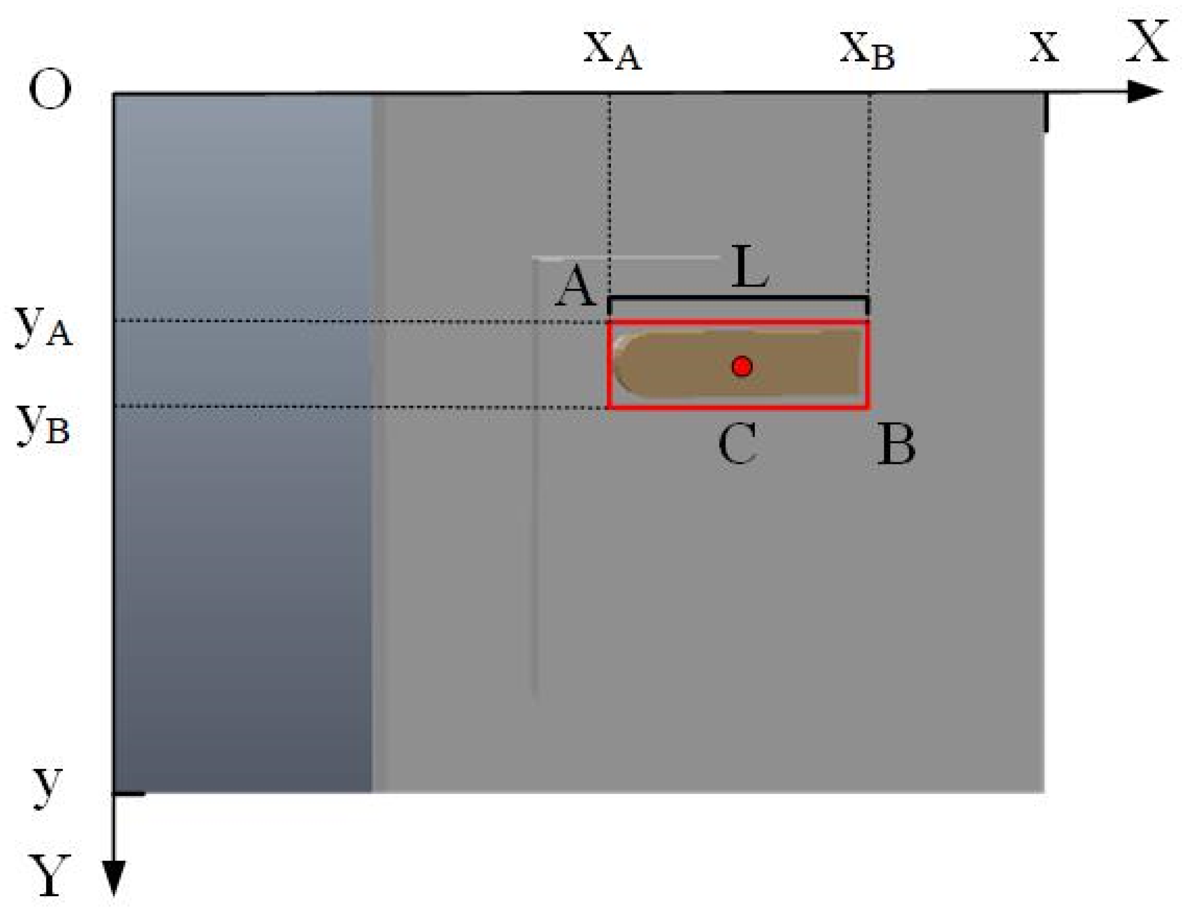
Figure 3 shows the recognition effect of the door handle when the camera is in the N state and establishes an XOY plane coordinate system, where L represents the length of the door handle in the image. Moreover, A and B represent the two diagonal vertices of the recognition frame and C represents the center position of the door handle. By calculating the ratio of the actual length of the door handle to L multiplied by the distance of the center point C of the handle relative to the center of the picture, the position of the center point C of the door handle relative to the camera in the XOY plane can be solved in practice.
2.3. Kinematics Model of the Robotic Arm
In the experiment, the Denavit–Hartenberg (D-H) modeling method was used to establish the kinematics model of the mobile robotic arm [23]. This method is widely used in robot kinematics modeling to establish an integral link coordinate system. In the multi-link series robotic arm system shown in Figure 4, the kinematics model of the robotic arm is established by homogeneous coordinate transformation.
The corresponding D-H parameters of the robotic arm are shown in Table 1.
Equations for each link of the robotic arm:
The kinematic model of the base corresponding to the end of the robotic arm can be obtained by multiplying each link coordinate system equation. represents the coordinates of the endpoint of the end robotic arm in the base coordinate system.
This method derives the transformation matrix from the base coordinate system to the end coordinate system. During the forward kinematics calculation, the position and posture of the coordinate system of the end of the robotic arm are obtained according to the known joint variables. The inverse kinematics calculation solves the value of the joint variables based on the known pose of the end coordinate system. An accurate model is established to lay a good foundation for subsequent experiments.
2.4. Door Opening Trajectory of the Mobile Robotic Arm
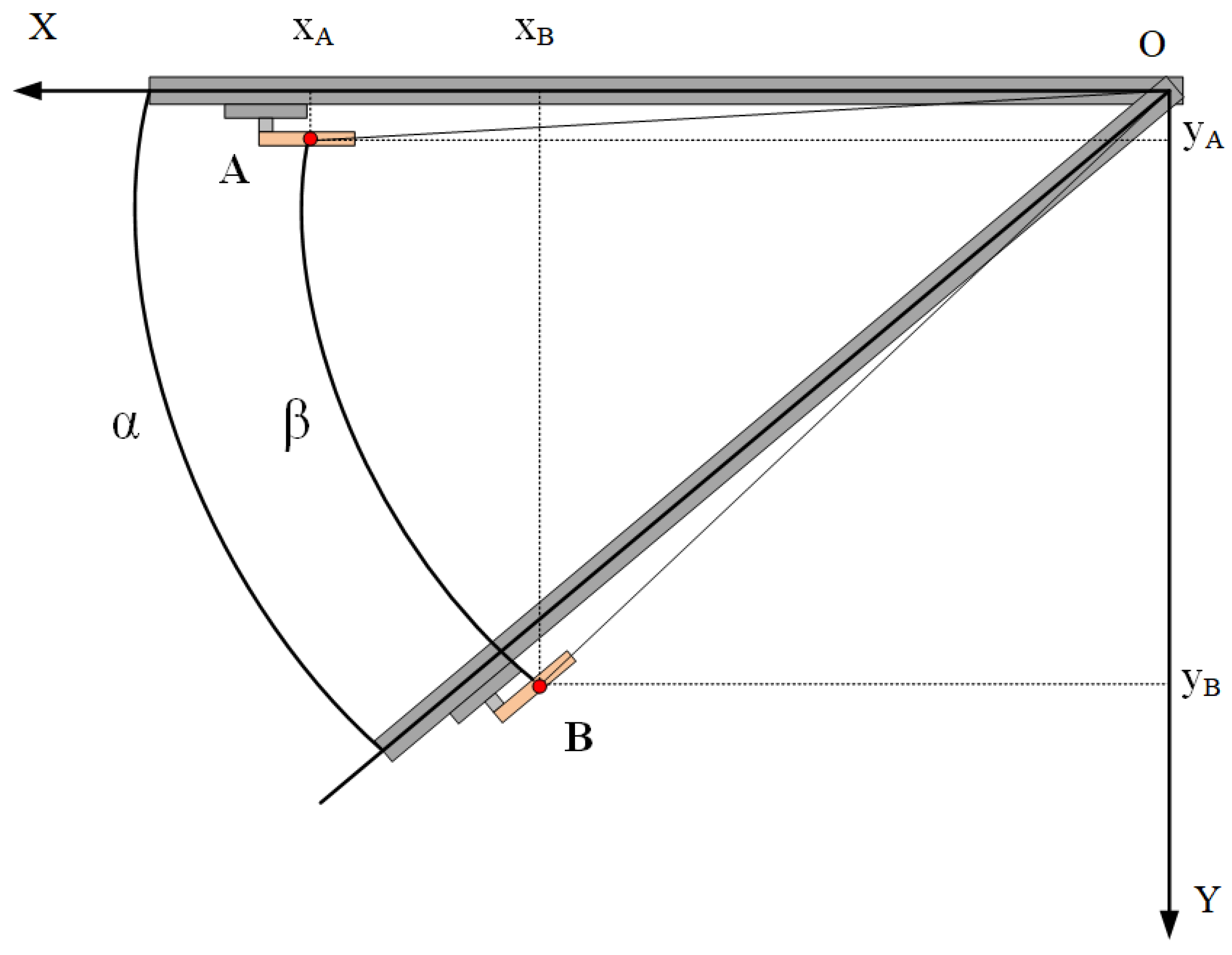
The door-opening trajectory of the mobile robotic arm is limited to the rotation angle of the door axis and the door handle. The following Figure 5 shows the process of the door rotating from A to B around the door axis O. The rotation angle of the door handle around the door axis is the same as the door rotation angle .
The gripping position of the door handle is set as the initial point of the trajectory, and the force analysis is conducted using the lever principle. Less force is required to turn the door handle as the force is applied away from the door handle pivot axis. Here, the grasping position is set to 3/4 of the length of the door handle, and the robotic arm can reduce the grasping force as much as possible to complete the grasping operation without falling off. Under these constraints, the trajectory of the robotic arm’s end is determined. As shown in Figure 6, rotate the handle from A around M to B to complete the twisting of the handle, and then around the door axis N from B to C to realize the door-opening action.
3. Reinforcement Learning PPO Algorithm and Improved PPO Method
For the traditional control algorithm of the robotic arm, there are multiple solutions of target position, which makes the exploration efficiency of the end of the robotic arm inefficient with the increase of dimension. The reinforcement learning method is used to improve the control efficiency and stability of the robotic arm. During the interaction between the robotic arm and the environment, the reward feedback optimization strategy of the environment for the action in the current state is used to realize a better control strategy under specific performance indicators.
3.1. Principle of PPO Algorithm
The PPO (proximal policy optimization) algorithm can deal with large-scale and continuous space control, which is suitable for continuous actions such as robotic arm grasping. The key idea of the PPO algorithm is to limit the update range of the new strategy by adjusting the proportion of the new strategy and the old strategy to solve the problem that it is difficult to determine the value of the learning rate. This restriction prevents the strategy from converging when the learning rate is too large, and the training time is long when the learning rate is too low. This restriction can effectively improve the control efficiency of the robotic arm and improve the stability of the control.
PPO is improved based on TRPO (trust region policy optimization) algorithm. In view of the low sampling efficiency of the TRPO algorithm, the PPO algorithm adopts the method of importance sampling to solve the problem. The algorithm can improve the efficiency and reliability of TRPO data when only first-order optimization is used. The size of the TRPO policy update is constrained to maximize the alternative objective function [17].
The constraints represents the estimator of the dominance function over time, and the expectation represents the empirical mean of a finite batch of samples. and represent the old and new strategies, respectively, which are reflected in the corresponding state of the action . Using KL divergence limits the expectation to [17].
Introduce probability ratios [17].
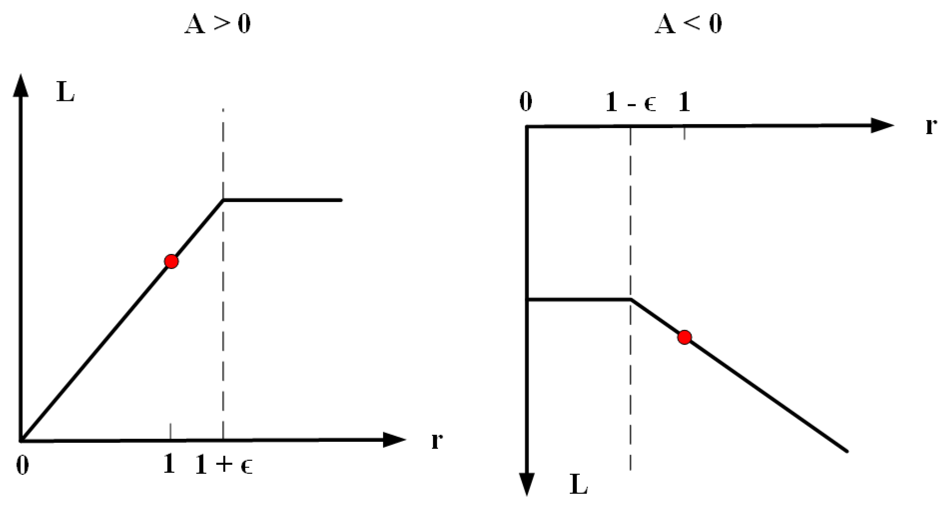
Without constraints, maximizing CPI causes the gradient to explode, penalizing changes that move the ratio away from 1 to solve this problem. The expected expression corresponding to the main goal is as follows [17].
3.2. Improvement of PPO Algorithm
In the reinforcement learning PPO method, the agent continuously obtains experience and rewards in action during the training process and trains the model through these data. Full data coverage cannot be achieved in the real environment, so the agent will think that the reward problem will prolong the training process and reduce the training efficiency.
To reduce the appearance of sparse rewards, this paper is an improved method of reward shaping for PPO. This method randomly selects a certain number of states in the sequence as the new target when the sequence length reaches or exceeds the target during the reinforcement learning training process. The purpose of optimization is achieved by modifying the set goals. Set T as the target the robotic arm needs to move. During the training process, the robotic arm has a certain distance from target T through the trajectory. In addition, the current position L is expanded to the experience pool, and the sparse reward is changed into a non-sparse reward.
When the robotic arm fails to reach the target position in the exploration process, this method saves the coordinate position that the robotic arm can traverse. Furthermore, it increases the storage of learning experience value, reduces the exploration of the robotic arm for the useless environment, and solves the problem of the long training time of the robotic arm.
3.3. Definition of State Space and Action Space
The state space mainly includes the base of the robotic arm, the relative position between the end of the robotic arm and the target, the rotation coordinates of each joint of the robotic arm under limited conditions, and the state of the end of the robotic arm. is set as the reward function of the state space, represents the reward weight, and the reward function equation of the relative distance between the gripper and the target T is established.
The action space design lies in the rotation angle of each joint of the base and the robotic arm and includes the rotation angle when the end clamping claw holds the target. The base, boom, jib, and wrist of the robotic arm rotate around the axis respectively and set the rotation angle around the axis and the corresponding value range. Based on the actual performance parameters of the robotic arm, the action space is defined, as shown in Table 2, with a total of seven groups of data.
Design the reward function of the action space.
3.4. Design of Reward Function
To solve the problem of sparse grasping rewards for robotic arms, formal rewards were used to improve learning efficiency. The state action is updated and trained according to the distance reward function network. The end gripper of the robotic arm can get the reward value of the target distance after each action. The training process of reinforcement learning tends to increase in the direction of reward, and the reward value increases gradually with the decrease of distance. The training makes the end-effector of the robotic arm tend to be close to the door handle and the reward function of grasping. The final reward function is defined as a linear combination of state and action space.
represents the reward value of the distance between the end of the mobile robotic arm and the door handle in the state space, represents the reward function in the action space, and it is designed that the rotation angles of all joints are accumulated into and the reward for completing the grasping action. represents the penalty function of the collision to avoid collision.
4. Results of Simulation Experiment
To assess the reliability of the method, a simulation environment and a realistic experimental scenario are experimentally set up. For the control task of opening doors on a mobile robotic arm platform, reinforcement learning algorithms such as TRPO, PPO and improved PPO are tested in the simulation environment. The reward values corresponding to the algorithms are used as key metrics to compare the merits. The models with good training results are applied to the recognition grasping task of the mobile robotic arm in a realistic scenario.
4.1. Construction of the Simulation Environment
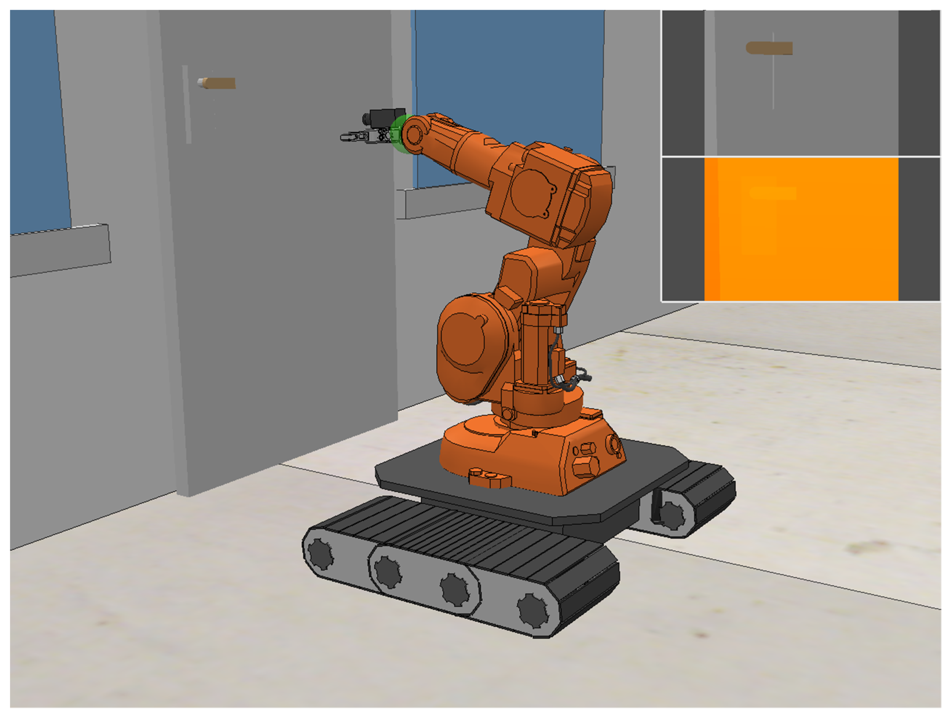
CoppeliaSim is a robotics simulation platform with an integrated development environment. The platform has a rich physics engine for building cross-platform simulation environments. As shown in Figure 8, the main body of the mobile robotic arm is built from a combination of the arm, track, camera, and jaws in CoppeliaSim, and the mobile arm is sized to match the actual structure and dimensions.
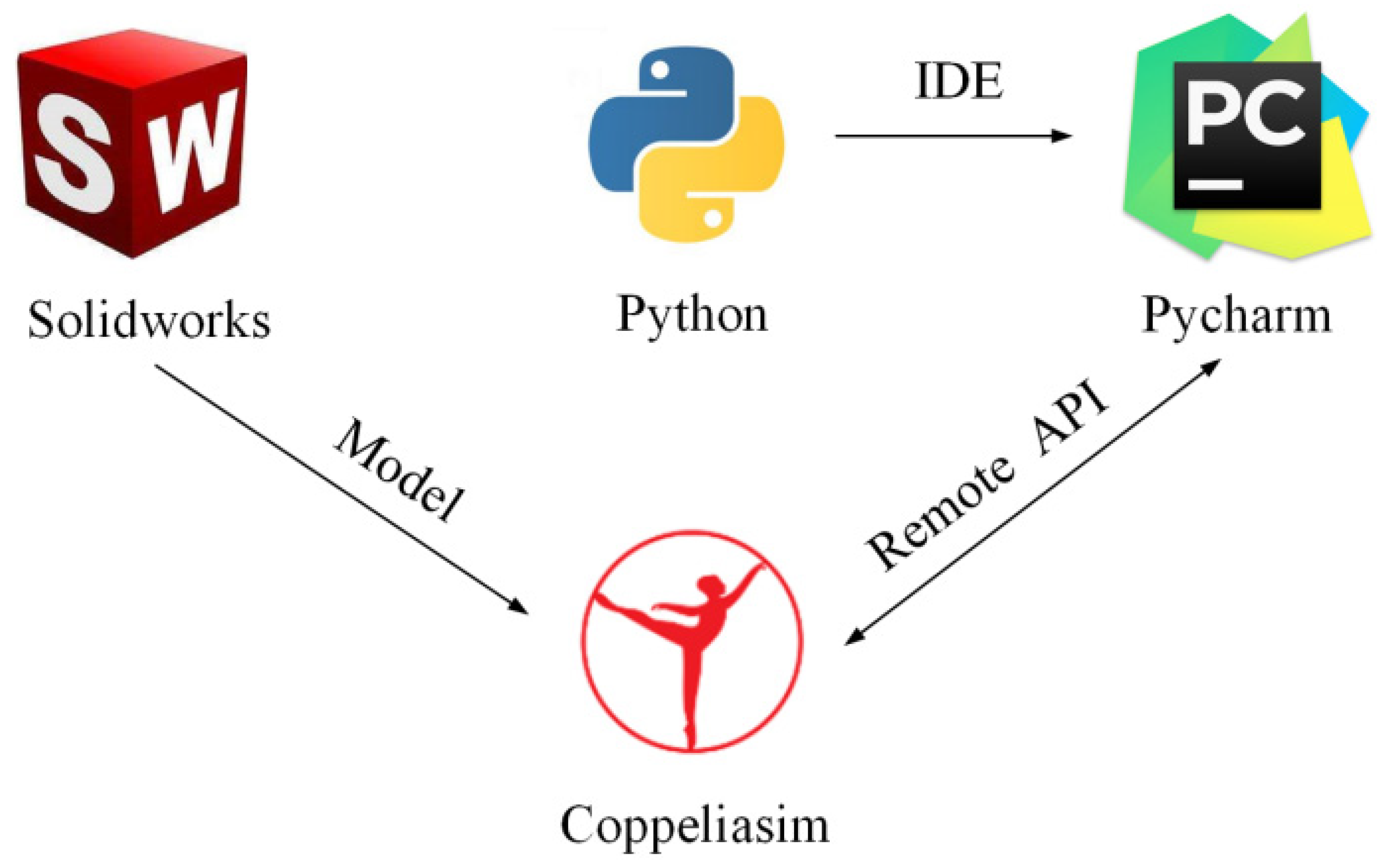
As shown in Figure 9, Python controls the movements of the mobile arm platform in CoppeliaSim through the API interface, providing a good experimental environment to verify whether the mobile arm can accurately follow the control procedure to open the door.
4.2. Results of Simulation Experiments
For the task of opening the door of the mobile robotic arm, the effectiveness of the reinforcement learning algorithms of different types of strategies is verified. The hardware aspect of the experiment uses an RTX4000 graphics card, the compilation language uses Python, and the overall network framework is built by PyTorch. The following Table 3 shows the training parameters for setting the training network.
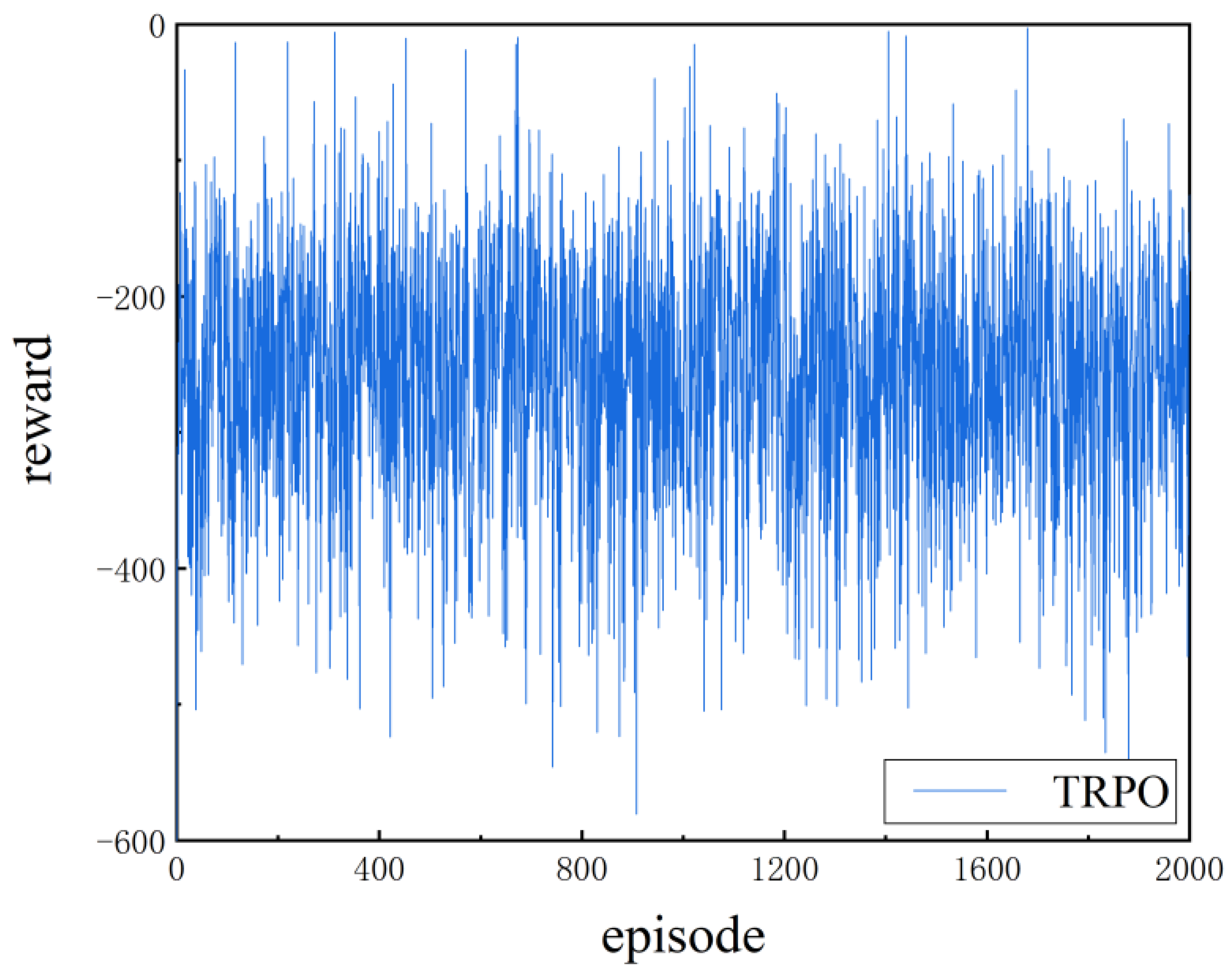
Under the same training parameters, the following training is performed on TRPO, PPO, and improved PPO. The reward value is obtained for each training cycle during the training process; the horizontal and vertical axis represents the reward value corresponding to the number of training cycles. The TRPO reward curve of the training process is shown in the following Figure 10.
By analyzing the reward value curve, it is concluded that the TRPO algorithm has not completed convergence within 2000 episodes and the output reward value fluctuates, and the training effect of the method is poor.
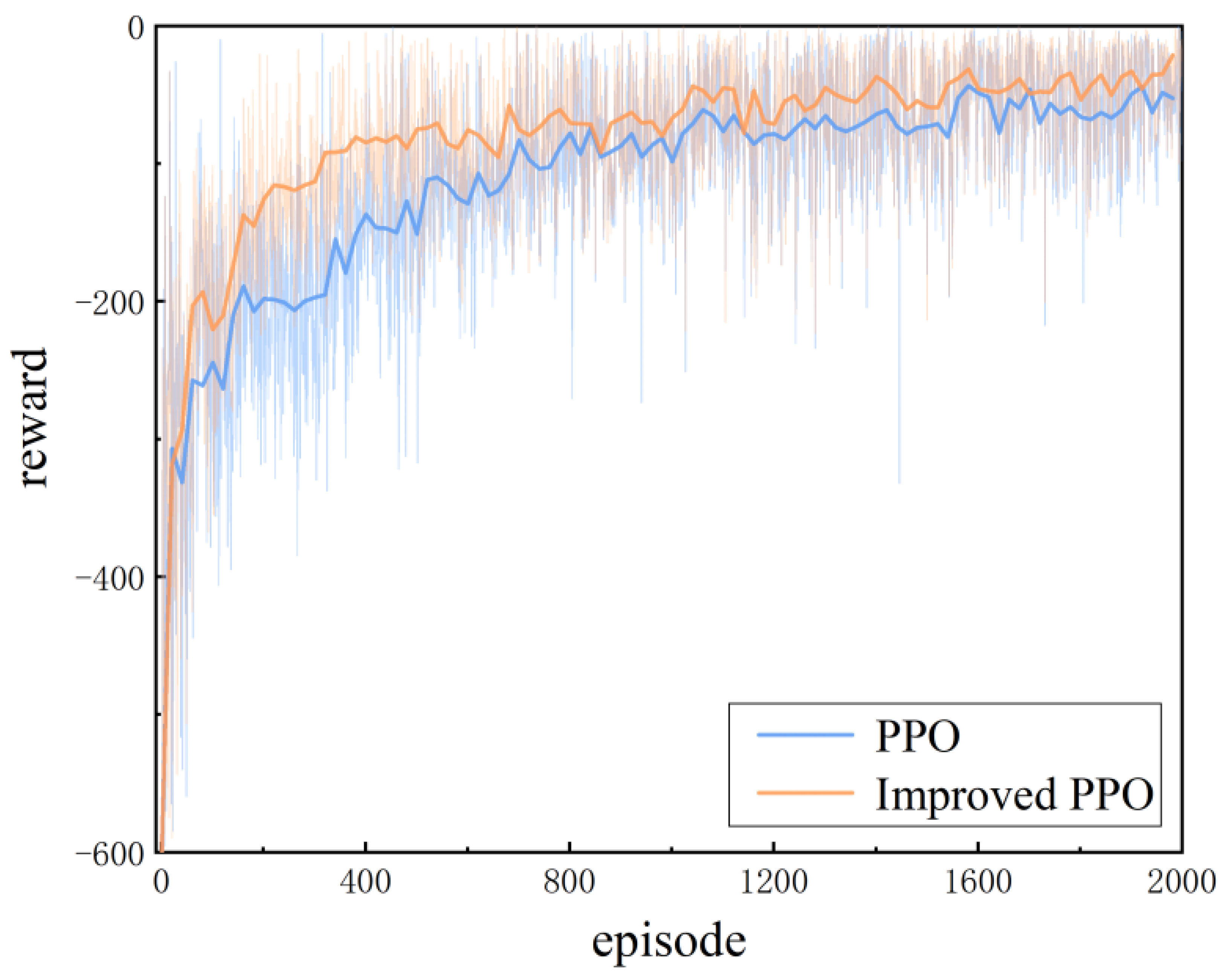
Figure 11 shows the relationship between the reward value of the PPO and the improved PPO algorithm and the training round. The reward value of the PPO algorithm at 800 training rounds is equivalent to the reward value of the improved PPO algorithm at about 400 training rounds. When the reward values corresponding to the two algorithms tend to be stable, it is obvious that the improved PPO algorithm has a smaller range of reward values than the PPO algorithm. This shows that the method of expanding the experience base used by the algorithm has played a good role, and the improved PPO algorithm has fast convergence speed and stability.
4.3. Joint Simulation Experiments
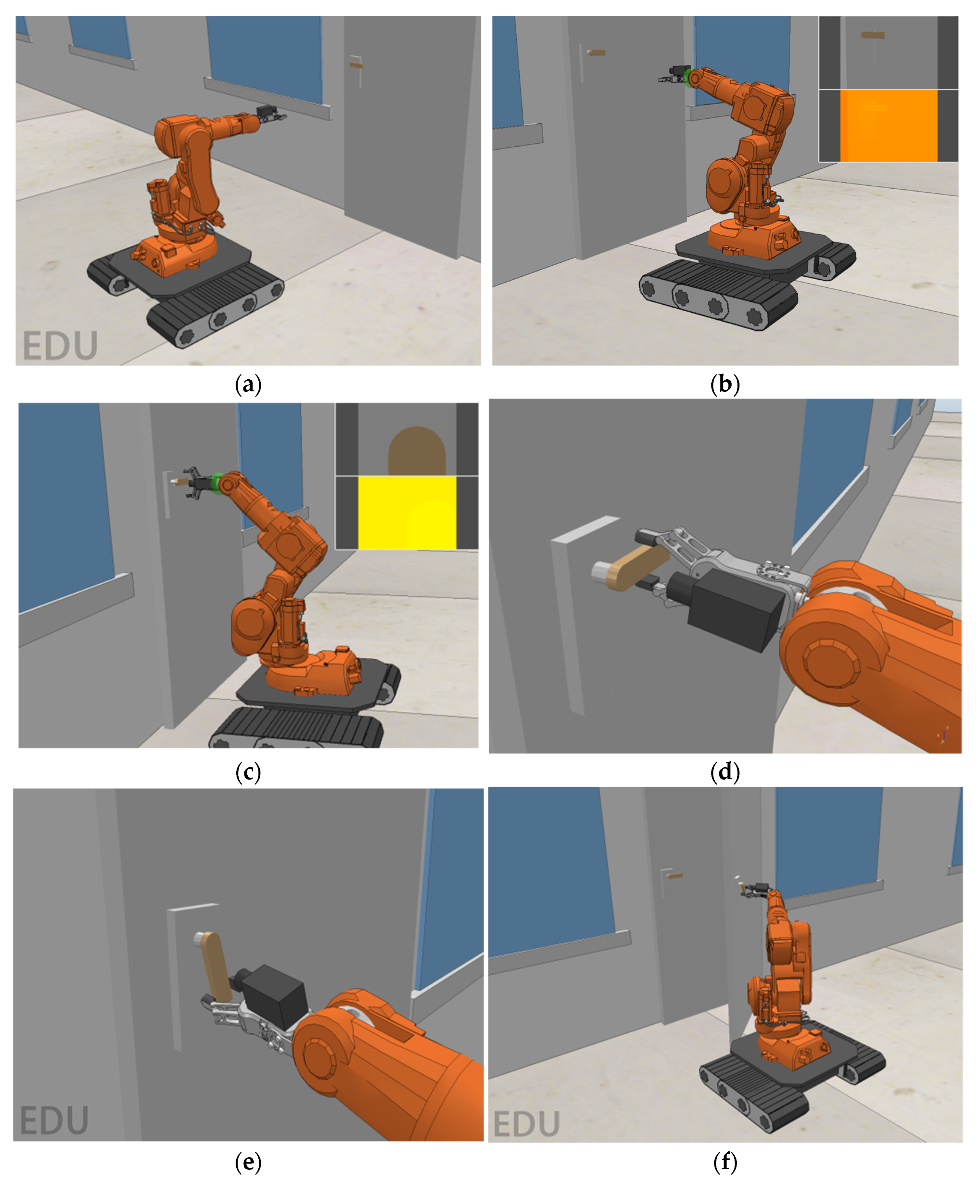
The experimental simulation platform adopts the method of joint simulation, and Python controls CoppeliaSim through an API interface to realize the control of the motion simulation of the mobile robotic arm. Figure 12 shows that after the robotic arm is moved to the front door to adjust the posture, the trained strategy is applied to the platform opening operation of the mobile robot arm, according to the three-dimensional position of the door handle relative to the moving robotic arm.
The experiment uses the proposed improved PPO algorithm control strategy in the experiment. Figure 12a shows the mobile robotic arm platform moving to the operation area and adjusting the position. Figure 12b–d show the grasping operation process of the robotic arm reaching the grasping position according to the relative position information. Figure 12e,f show the mobile robotic arm completing the door-opening operation. The simulation experiment simulates the process of the mobile robotic arm platform completing the door-opening operation, which has realistic guidance significance for the mobile robotic arm platform completing the door-opening operation.
5. Results and Discussion of Physical Experiment
The mobile robotic arm platform mainly includes the robotic arm, crawler car, camera, gripper, etc. First, after the mobile robotic arm platform reaches the working area, it adjusts to a state parallel to the door through its position and attitude information. The camera and the robotic arm form a hand–eye system. The mobile robotic arm platform determines the target of the door handle and calculates the relative position through the method of target detection. Finally, the model trained in the simulation environment is applied to the actual crawling experiment. In addition, the crawling success rates of TRPO, PPO, and improved PPO algorithms are compared to verify the effectiveness of the control strategy of improved PPO algorithms.
5.1. Object Detection and Positioning
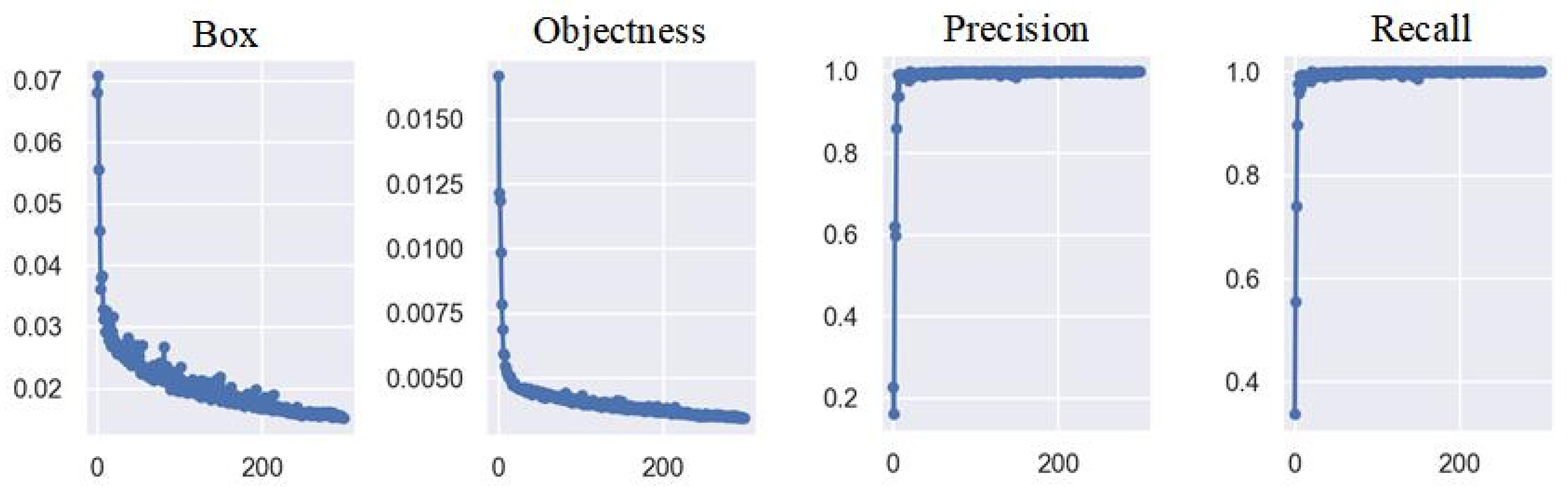
Based on the PyTorch framework, the operating environment is set up, the dataset is trained using the YOLOv5 model, the number of training iterations of the dataset is set to 300 times, and the main data change as the number of iterations increases during the training process.
The value Box in Figure 13 represents the average of GIoU loss as a loss function for the bounding box, and the more accurate the value is, the more accurate the target box annotation. Objectness detects the mean loss for the target, and the closer the value is to 0, the more accurate the target detection. Precision represents the ratio of an accurate positive class to all positive classes, and the closer to 1, the higher the accuracy.
Recall indicates the ratio of the correct number of targets marked to the total number of targets, and the closer to 1, the higher the accuracy.
The experimental training effect observes the fluctuation of accuracy and recall, and through the observation of experimental results it can be seen that the precision and recall fluctuation is small. After the training iteration reaches 300 times, the numerical changes tend to be stable, the trained model is assessed, and the recognition effect is as follows.
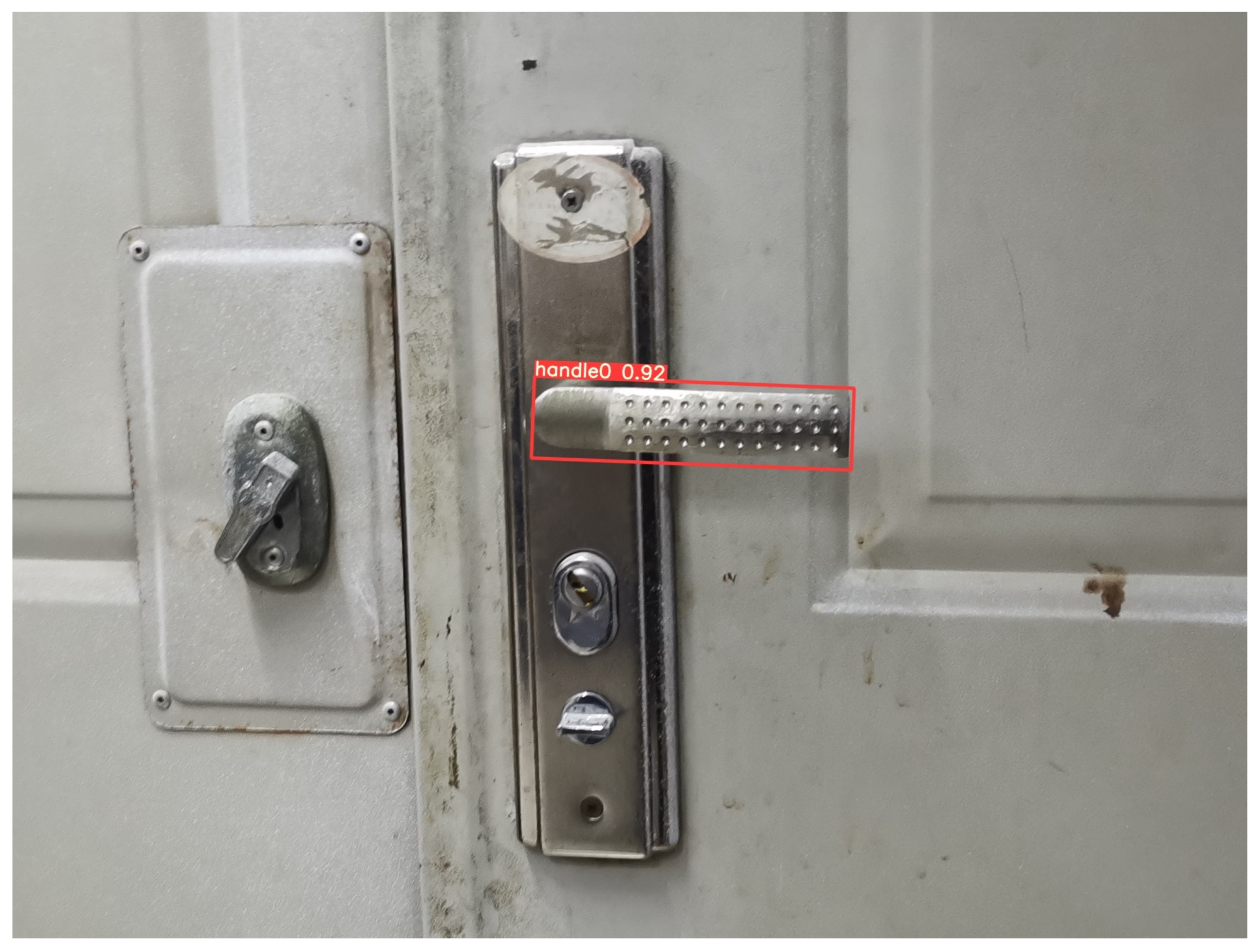
The door-handle recognition and detection models extract large amounts of feature information from images. As shown in Figure 14, the identification results show the frame with a better recognition frame selects the border of the door handle. The recognition rate is as high as 90%, and the experimental results show that the door-handle detection model based on the YOLOv5 model has the characteristics of high precision, good robustness, and fast speed.
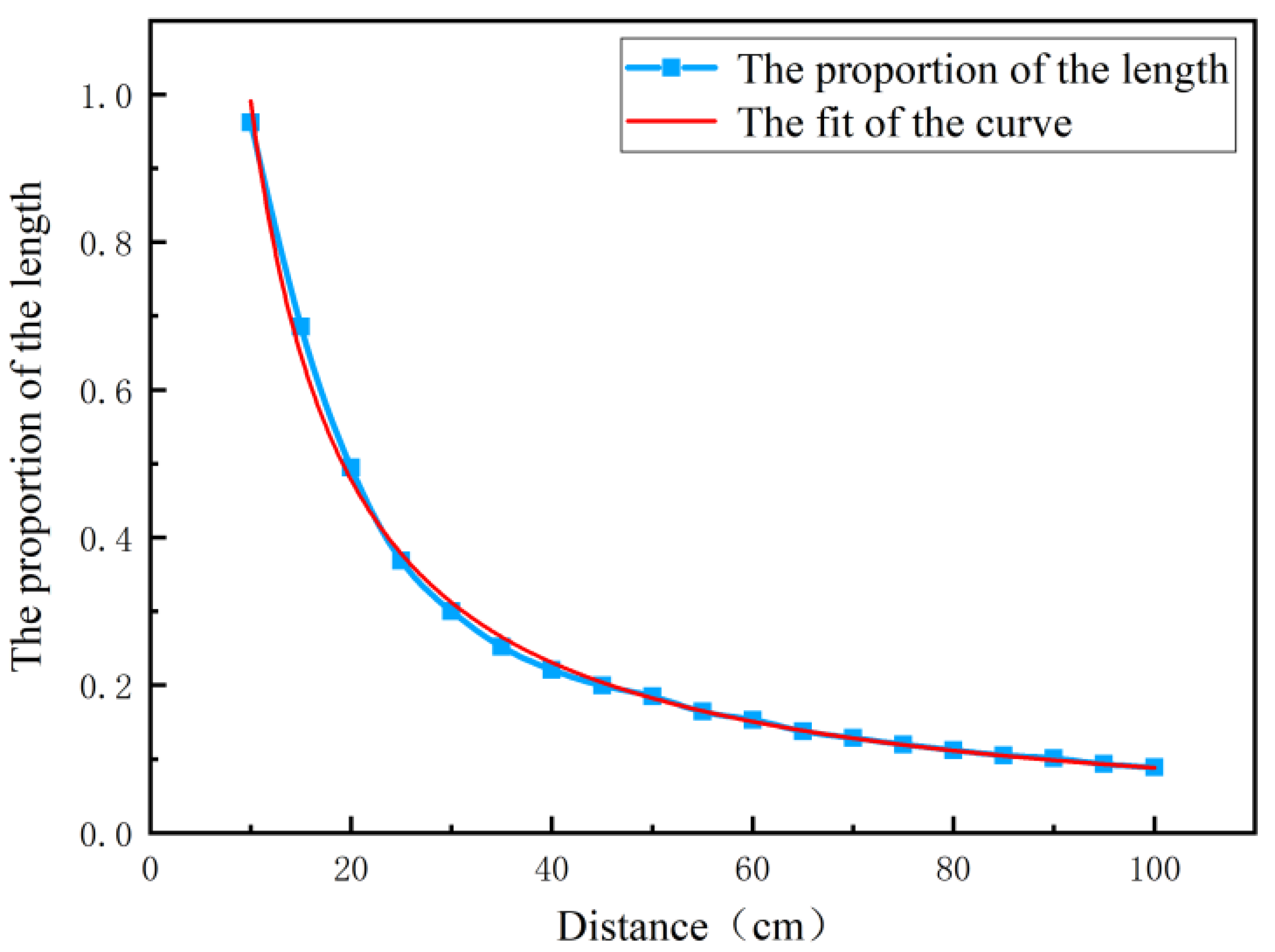
In this experiment, the vertical distance between the camera and the door plane and the ratio of the length of the recognition frame and the length of the picture is measured in the state of parallel plane constraint. The relationship between the two is described by fitting the curve. Moreover, the vertical distance between the moving robotic arm platform and the door plane is calculated according to the formula of the length proportion substituted into the fitted curve.
The experimental design of the door handle and the calculation of the platform is the distance of the mobile robotic arm. The ratio of the length of the recognition frame L to the length of picture x is the vertical coordinate K, and the vertical distance between the camera and the door plane is the abscissa D, with the units in centimeters. The experiment is limited to a distance of 10–100 cm, a total of 20 groups are separated by 5 cm, and each group measures the average of the length ratio K 10 times; the blue discrete data points are sampled, and the scatter points are connected using blue curves.
As shown in Figure 15, the red line represents the fitting curve used to approximately depict the functional relationship between the discrete point and the coordinates, which maximizes the approximation between the experimental data and the equation curve. The analysis shows that the length ratio approaches infinity when the spacing approaches zero, the length ratio is zero when the spacing approaches infinity, and the curve is a power series relationship. In addition, the relationship between the length ratio K and the spacing D is a power function obtained through curve fitting.
The fitted curve in Figure 15 is in line with the actual position of the motion trajectory. According to the fitted curve equation, the data are calculated mathematically, and the error between the calculation spacing and the actual distance is less than 4 mm when being substituted into any length ratio. The fitted curve can better complete the spacing prediction.
Through the above method, the YOLOv5 algorithm can detect the recognition classification, calculate the size and proportion of the corresponding recognition frame, and continuously update the three-dimensional coordinate information of the door handle relative to the mobile robotic arm platform during real-time object detection.
5.2. Experiments on Opening Doors
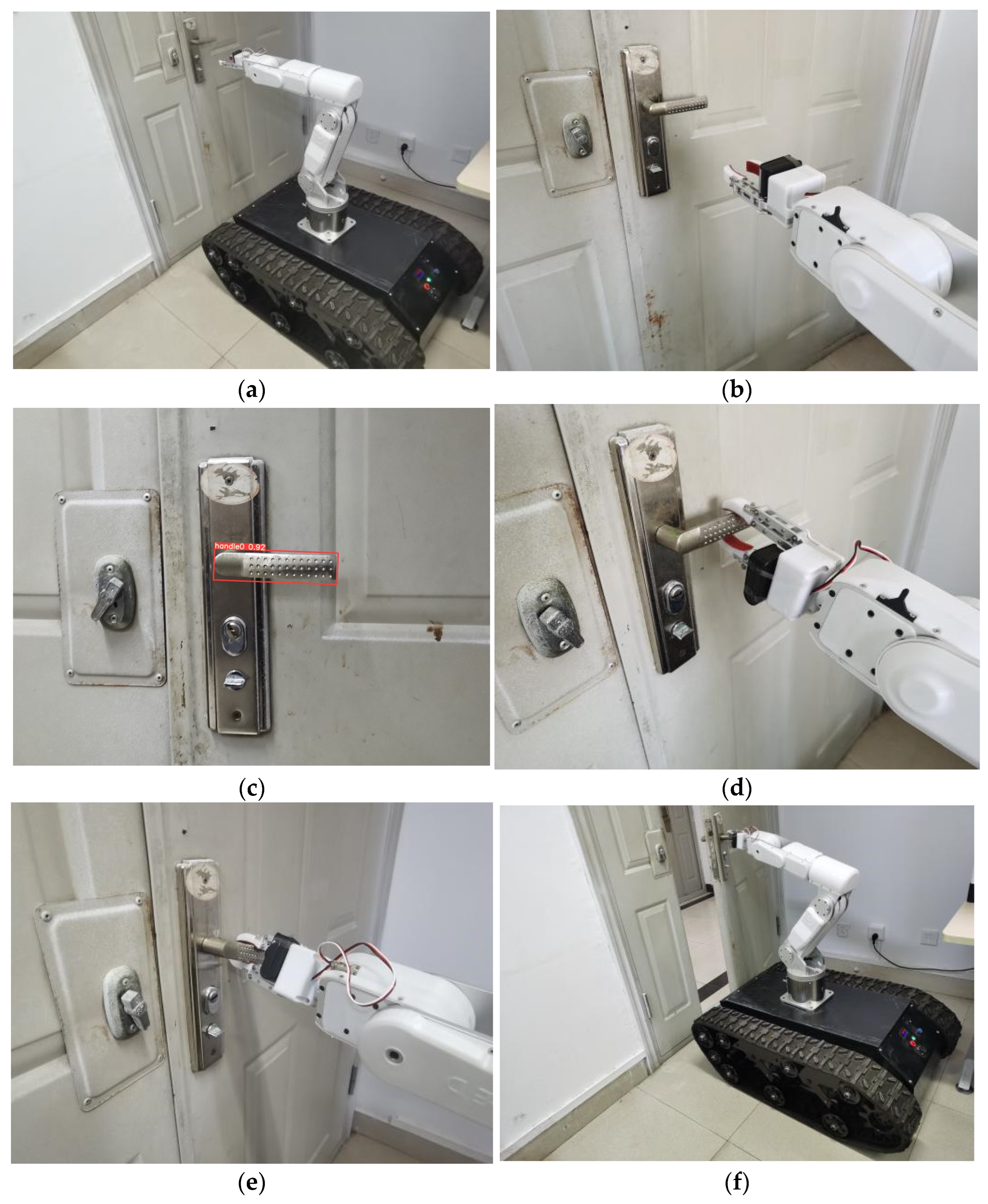
This paper solves the motion planning problem of the robotic arm based on reinforcement learning. After the mobile robotic arm obtains the position information of the door handle through image processing, the strategy learned in the simulation environment is applied to the path planning of the robotic arm. The end effector performs the grasping task and completes the opening task from the initial position to the target position.
The mobile robotic arm was tested in a real-life scenario. Figure 16a shows that the moving robotic arm platform moves to the door and adjusts the posture. Figure 16b,c show the lens of the robotic arm interacting with the door, indicating that the mobile robotic arm obtains image information through the camera to complete the recognition and positioning of the door handle. Figure 16d–f show that after the reinforcement learning model training, these strategic models are used to control the robotic arm system to complete the door-opening task.
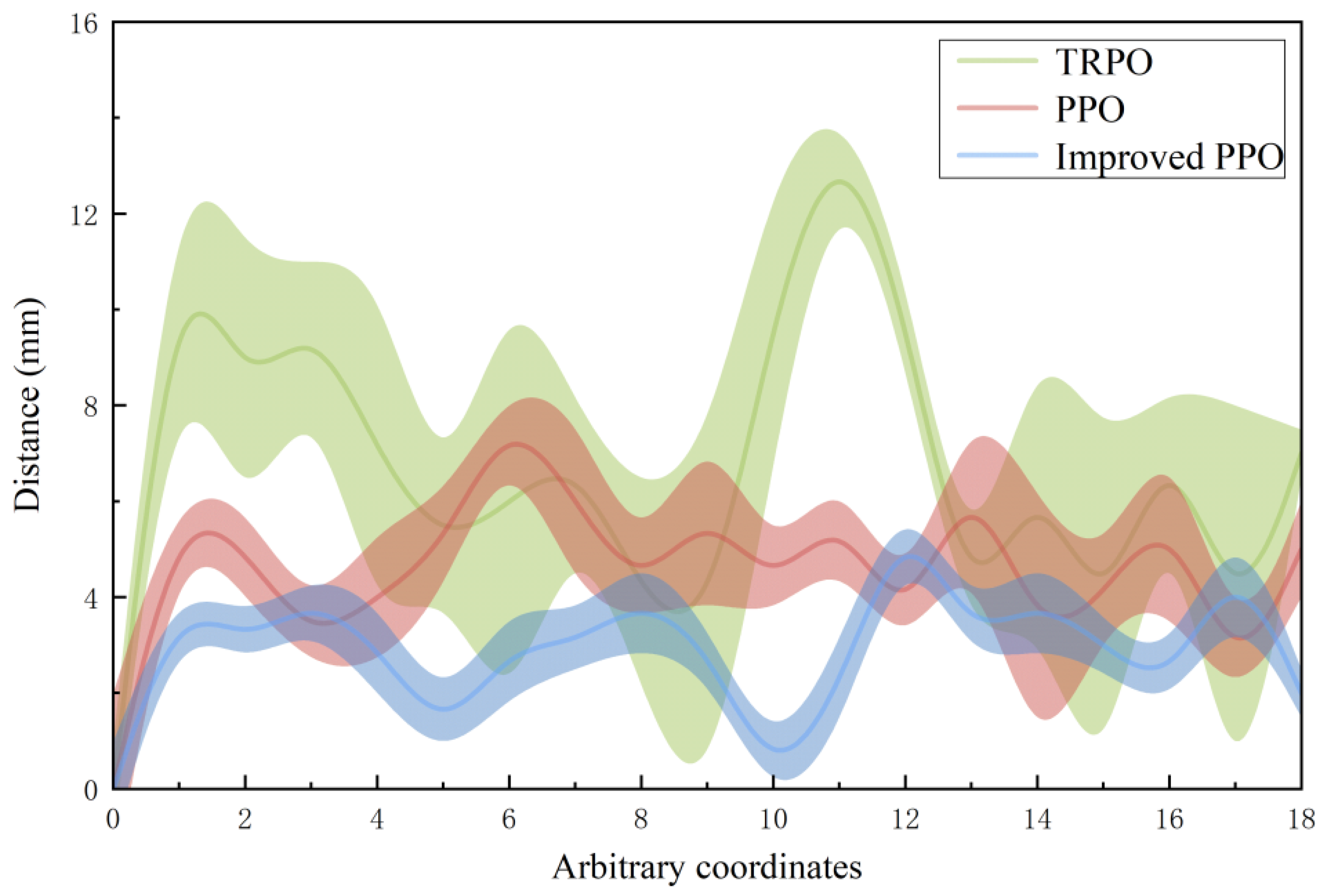
To verify the effectiveness of the algorithm in the door-opening operation, the mobile robotic arm adopts TRPO, PPO, and improved PPO algorithms, respectively, and sets 18 random coordinates as the target position, with 50 experiments in each group. Compare the distance between the end and the specified target after the mobile robotic arm completes the corresponding action according to the strategy under the condition of convergence.
According to the experimental results shown in Figure 17, when the TRPO and PPO algorithms are applied, the distance between the end of the robotic arm and the target position is relatively far, and the error band is wide, indicating that the stability of the method is poor. It is difficult to complete the grasping task. The improved PPO algorithm in the simulation experiment has a fast convergence speed and stable reward value. After adopting the strategy of improving the PPO algorithm in practical applications, the overall relative distance is the shortest, and stability is strong. This result validates the effectiveness of the improved approach.
6. Conclusions and Future Works
This paper proposes an improved method of reward shaping for PPO, which increases the storage of experience values during training, thus reducing the exploration of useless environments by the robotic arm. This method is applied to door opening with a mobile robotic arm. The robotic arm identifies and locates the door handle through the YOLOV5 method and applies the model trained in the simulation environment to the real grasping task. To measure the performance of the proposed method, this paper has also compared PPO with TRPO and improved PPO by comparing the solution quality using a reward indicator and actual error. The experimental results show that the improved PPO method has high accuracy and stability when completing the door-opening operation. This method has guiding significance for the door-opening task of the mobile robotic arm.
In future work, the application scenarios of mobile robotic arms will be expanded by adding various types of door handles. In addition, the experiment will use a higher-precision positioning system such as lidar to improve the accuracy of the mobile robotic arm.
Author Contributions
Conceptualization, L.W.; Project administration, Y.Z.; Writing—original draft, Y.W. All authors have read and agreed to the published version of the manuscript.
Funding
This work was supported in part by the National Natural Science Foundation of China (Grant No. 41771487).
Institutional Review Board Statement
Not applicable. This study did not involve humans or animals.
Informed Consent Statement
Not applicable. The study did not involve humans.
Data Availability Statement
The data presented in this study are available on request from the corresponding author. The data are not publicly available due to privacy of the subjects involved in the study.
Conflicts of Interest
The authors declare no conflict of interest.
References
- Liu, B. Recent Advancements in Autonomous Robots and Their Technical Analysis. Math. Probl. Eng. 2021, 2021, 6634773. [Google Scholar] [CrossRef]
- Cardenas, A.; Boodwine, B.; Skaar, S.; Seelinger, M. Vision-Based Control of a Mobile Base and On-Board Arm. Int. J. Robot. Res. 2003, 22, 677–698. [Google Scholar] [CrossRef]
- Huang, S.-J.; Huang, J.-C. Vision guided dual arms robotic system with DSP and FPGA integrated system structure. J. Mech. Sci. Technol. 2011, 25, 2067–2076. [Google Scholar] [CrossRef]
- Sharma, A.; Noel, M.M. Design of a low-cost five-finger anthropomorphic robotic arm with nine degrees of freedom. Robot. Comput.-Integr. Manuf. 2012, 28, 551–558. [Google Scholar] [CrossRef]
- Ali, M.M.; Hui, L.; Stoll, R.; Thurow, K. Arm grasping for mobile robot transportation using Kinect sensor and kinematic analysis. In Proceedings of the 2015 IEEE International Instrumentation and Measurement Technology Conference (I2MTC), Pisa, Italy, 11–14 May 2015; pp. 516–521. [Google Scholar]
- Renjith, R.; Reshma, R.; Arun, K.V. Design and implementation of traffic sign and obstacle detection in a self-driving car using SURF detector and Brute force matcher. In Proceedings of the 2017 IEEE International Conference on Power, Control, Signals and Instrumentation Engineering (ICPCSI), Chennai, India, 21–22 September 2017. [Google Scholar]
- Belda, K.; Rovny, O. Predictive control of 5 DOF robot arm of autonomous mobile robotic system motion control employing mathematical model of the robot arm dynamics. In Proceedings of the 2017 21st International Conference on Process Control (PC), Strbske Pleso, Slovakia, 6–9 June 2017. [Google Scholar]
- Chung, W.; Rhee, C.; Shim, Y.; Lee, H.; Park, S. Door-Opening Control of a Service Robot Using the Multifingered Robot Hand. IEEE Trans. Ind. Electron. 2009, 56, 3975–3984. [Google Scholar] [CrossRef]
- Arduengo, M.; Torras, C.; Sentis, L. A Versatile Framework for Robust and Adaptive Door Operation with a Mobile Manipulator Robot. arXiv 2019, arXiv:1902.09051. [Google Scholar]
- Finn, C.; Levine, S. Deep Visual Foresight for Planning Robot Motion. In Proceedings of the 2017 IEEE International Conference on Robotics and Automation (ICRA), Singapore, 29 May–3 June 2016. [Google Scholar]
- Yang, N.; Chen, D.; Hu, J. Quantised control of delayed Markovian jump systems with partly known transition probabilities. IET Control Theory Appl. 2021, 15, 372–389. [Google Scholar] [CrossRef]
- Littman, M.L. Markov games as a framework for multi-agent reinforcement learning. In Machine Learning, Proceedings of the Eleventh International Conference, New Brunswick, NJ, USA, 10–13 July 1994; Elsevier: Amsterdam, The Netherlands, 1994. [Google Scholar]
- Li, X.; Zhong, J.; Kamruzzaman, M.M. Complicated robot activity recognition by quality-aware deep reinforcement learning. Future Gener. Comput. Syst. 2020, 117, 480–485. [Google Scholar] [CrossRef]
- Lillicrap, T.P.; Hunt, J.J.; Pritzel, A.; Heess, N.; Erez, T.; Tassa, Y.; Silver, D.; Wierstra, D. Continuous control with deep reinforcement learning. arXiv 2015, arXiv:1509.02971. [Google Scholar]
- Lötzsch, W. Using Deep Reinforcement Learning for the Continuous Control of Robotic Arms. arXiv 2018, arXiv:1810.06746. [Google Scholar]
- Schulman, J.; Levine, S.; Moritz, P.; Jordan, M.I.; Abbeel, P. Trust Region Policy Optimization. Comput. Sci. 2015, 1889–1897. [Google Scholar]
- Schulman, J.; Wolski, F.; Dhariwal, P.; Radford, A.; Klimov, O. Proximal Policy Optimization Algorithms. arXiv 2017, arXiv:1707.06347. [Google Scholar]
- Kamali, K.; Bonev, I.A.; Desrosiers, C. Real-time Motion Planning for Robotic Teleoperation Using Dynamic-goal Deep Reinforcement Learning. In Proceedings of the 2020 17th Conference on Computer and Robot Vision (CRV), Ottawa, ON, Canada, 13–15 May 2020. [Google Scholar]
- Canedo, D.; Fonseca, P.; Georgieva, P. A Deep Learning-Based Dirt Detection Computer Vision System for Floor-Cleaning Robots with Improved Data Collection. Technologies 2021, 9, 94. [Google Scholar] [CrossRef]
- Ren, S.; He, K.; Girshick, R.; Sun, J. Faster R-CNN: Towards Real-Time Object Detection with Region Proposal Networks. IEEE Trans. Pattern Anal. Mach. Intell. 2017, 39, 1137–1149. [Google Scholar] [CrossRef] [PubMed] [Green Version]
- Liu, W.; Anguelov, D.; Erhan, D.; Szegedy, C.; Reed, S.; Fu, C.Y.; Berg, A.C. SSD: Single Shot MultiBox Detector. In Lecture Notes in Computer Science; Springer: Cham, Switzerland, 2016. [Google Scholar]
- Redmon, J.; Farhadi, A. YOLOv3: An Incremental Improvement. arXiv 2018, arXiv:1804.02767. [Google Scholar]
- Zhuang, H.; Roth, Z.S. A complete and parametrically continuous kinematic model. IEEE Trans. Robot. Autom. 1992, 8, 451–463. [Google Scholar] [CrossRef]
Figure 1.
The structure diagram of the YOLOv5 model.

Figure 2.
The position transformation of the camera.

Figure 3.
The object recognition of the N state.

Figure 4.
Reference frame representation used in kinematic calculations of the robotic arm.

Figure 5.
The schematic diagram of the door-opening track.

Figure 6.
The schematic diagram of the trajectory of the mobile robotic arm.

Figure 7.
The objective function corresponding to the interval.

Figure 8.
The simulation experiment platform.

Figure 9.
The construction of the joint simulation experiment platform.

Figure 10.
The relationship between the reward value of the TRPO algorithm and the number of rounds.
Figure 10.
The relationship between the reward value of the TRPO algorithm and the number of rounds.

Figure 11.
The relationship between the reward value of PPO and the improved PPO algorithm and the number of training rounds.
Figure 11.
The relationship between the reward value of PPO and the improved PPO algorithm and the number of training rounds.

Figure 12.
The effect of the simulation experiment. (a) The platform moving to the operation area. (b) Adjusting the position. (c) The platform capture the image. (d) The grasping operation. (e) Revolving door handle. (f) The door-opening operation.
Figure 12.
The effect of the simulation experiment. (a) The platform moving to the operation area. (b) Adjusting the position. (c) The platform capture the image. (d) The grasping operation. (e) Revolving door handle. (f) The door-opening operation.

Figure 13.
Visualize of results.

Figure 14.
The effect of two types of door handle recognition.

Figure 15.
The results of the spacing test under different cumulative length ratios.

Figure 16.
The effect of the simulation experiment. (a) The platform moving to the operation area. (b) Adjusting the position. (c) Image recognition. (d) The grasping operation. (e) Revolving door handle. (f) The door-opening operation.
Figure 16.
The effect of the simulation experiment. (a) The platform moving to the operation area. (b) Adjusting the position. (c) Image recognition. (d) The grasping operation. (e) Revolving door handle. (f) The door-opening operation.

Figure 17.
The relationship between the end of the robotic arm and the distance of the random target under three algorithms.
Figure 17.
The relationship between the end of the robotic arm and the distance of the random target under three algorithms.


Table 1.
The D-H parameters of the robotic arm.
| Joint Serial Number | Connecting Rod Length (cm) | Connecting Rod Twist (°) | Offset of Link (cm) | Joint Rotation Angle (°) |
|---|---|---|---|---|
| 1 | 90 | |||
| 2 | 0 | 0 | ||
| 3 | 0 | 90 | 0 | |
| 4 | 0 | 90 | ||
| 5 | 0 | 90 | 0 | |
| 6 | 0 | 0 | 0 |
Table 2.
The definition of action space.
| Mechanical Arm Component | Direction of Rotation | Rotation Range (°) | Range of Values |
|---|---|---|---|
| Pedestal S | |||
| Main arm E0 | |||
| Forearm E1 | |||
| Wrist E2 | |||
| Gripper W |
Table 3.
The setting of training parameters.
| Training Parameter | Value |
|---|---|
| Clip | 0.2 |
| Gamma | |
| Episode | |
| Batch_size | 256 |
| Learning_rate | |
Publisher’s Note: MDPI stays neutral with regard to jurisdictional claims in published maps and institutional affiliations. |
© 2022 by the authors. Licensee MDPI, Basel, Switzerland. This article is an open access article distributed under the terms and conditions of the Creative Commons Attribution (CC BY) license (https://creativecommons.org/licenses/by/4.0/).
Share and Cite
MDPI and ACS Style
Wang, Y.; Wang, L.; Zhao, Y. Research on Door Opening Operation of Mobile Robotic Arm Based on Reinforcement Learning. Appl. Sci. 2022, 12, 5204. https://0-doi-org.brum.beds.ac.uk/10.3390/app12105204
AMA Style
Wang Y, Wang L, Zhao Y. Research on Door Opening Operation of Mobile Robotic Arm Based on Reinforcement Learning. Applied Sciences. 2022; 12(10):5204. https://0-doi-org.brum.beds.ac.uk/10.3390/app12105204
Chicago/Turabian StyleWang, Yang, Liming Wang, and Yonghui Zhao. 2022. "Research on Door Opening Operation of Mobile Robotic Arm Based on Reinforcement Learning" Applied Sciences 12, no. 10: 5204. https://0-doi-org.brum.beds.ac.uk/10.3390/app12105204
Note that from the first issue of 2016, this journal uses article numbers instead of page numbers. See further details here.