
Automatic 3D MRI-Ultrasound Registration for Image Guided Arthroscopy

 , and
, and
Abstract
:1. Introduction
2. Data
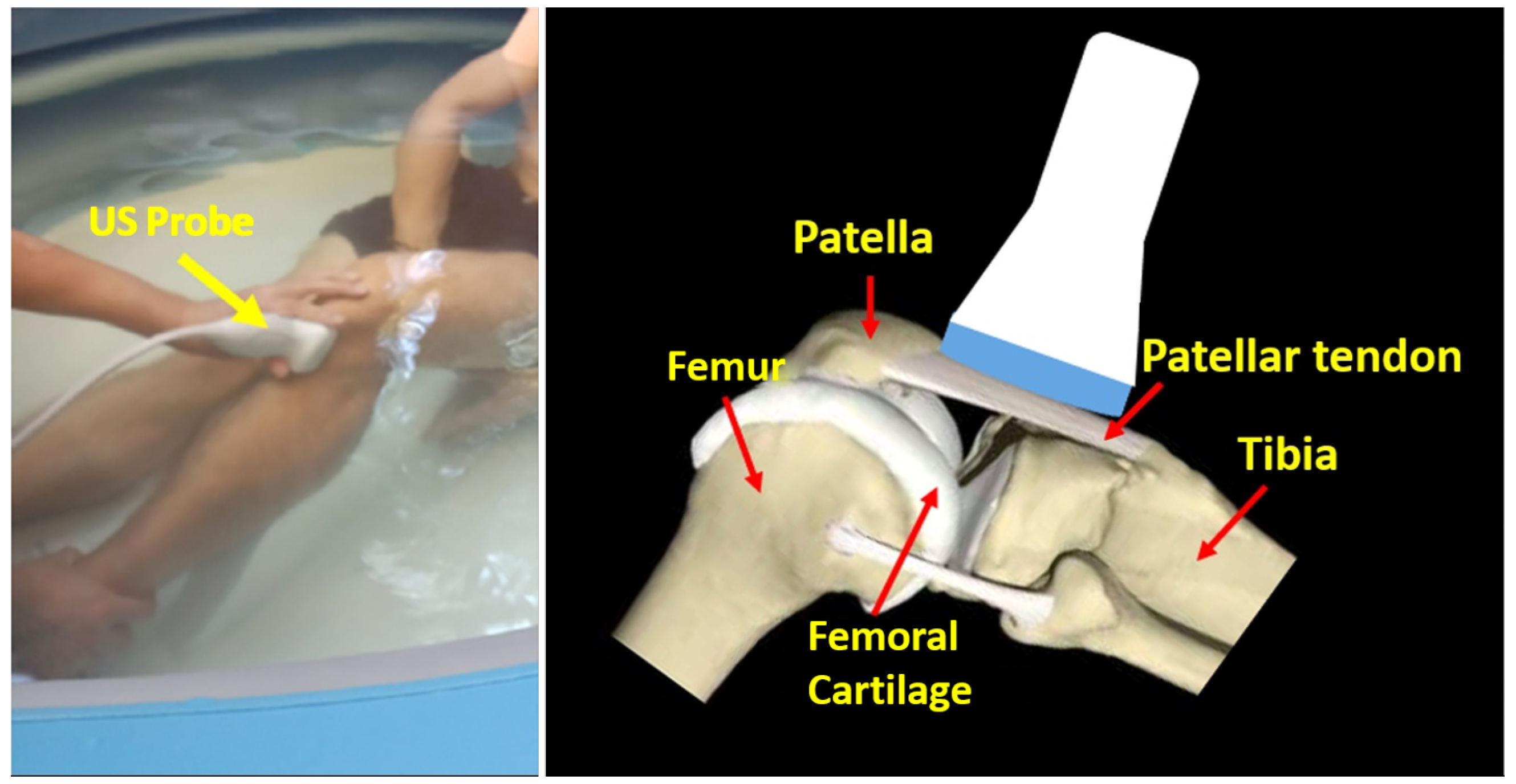
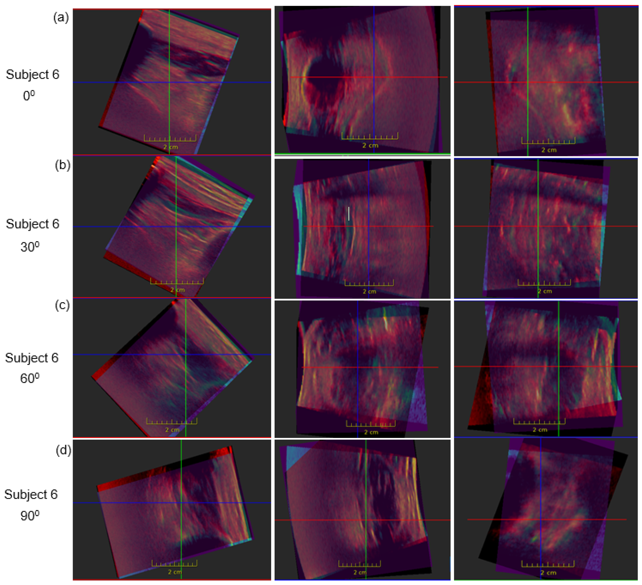
2.1. Ultrasound Data
2.2. MRI Data
3. Methods
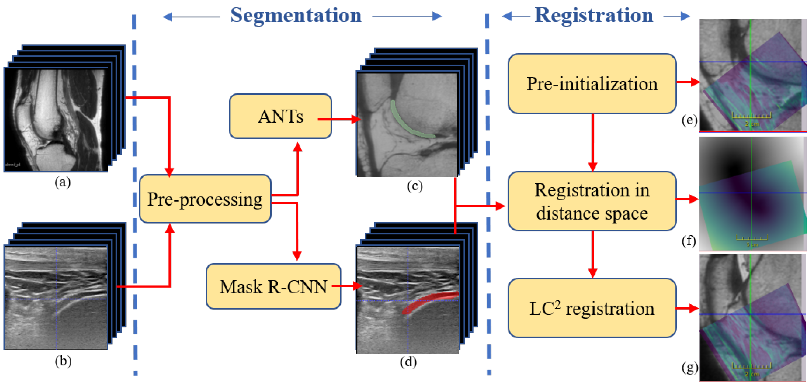
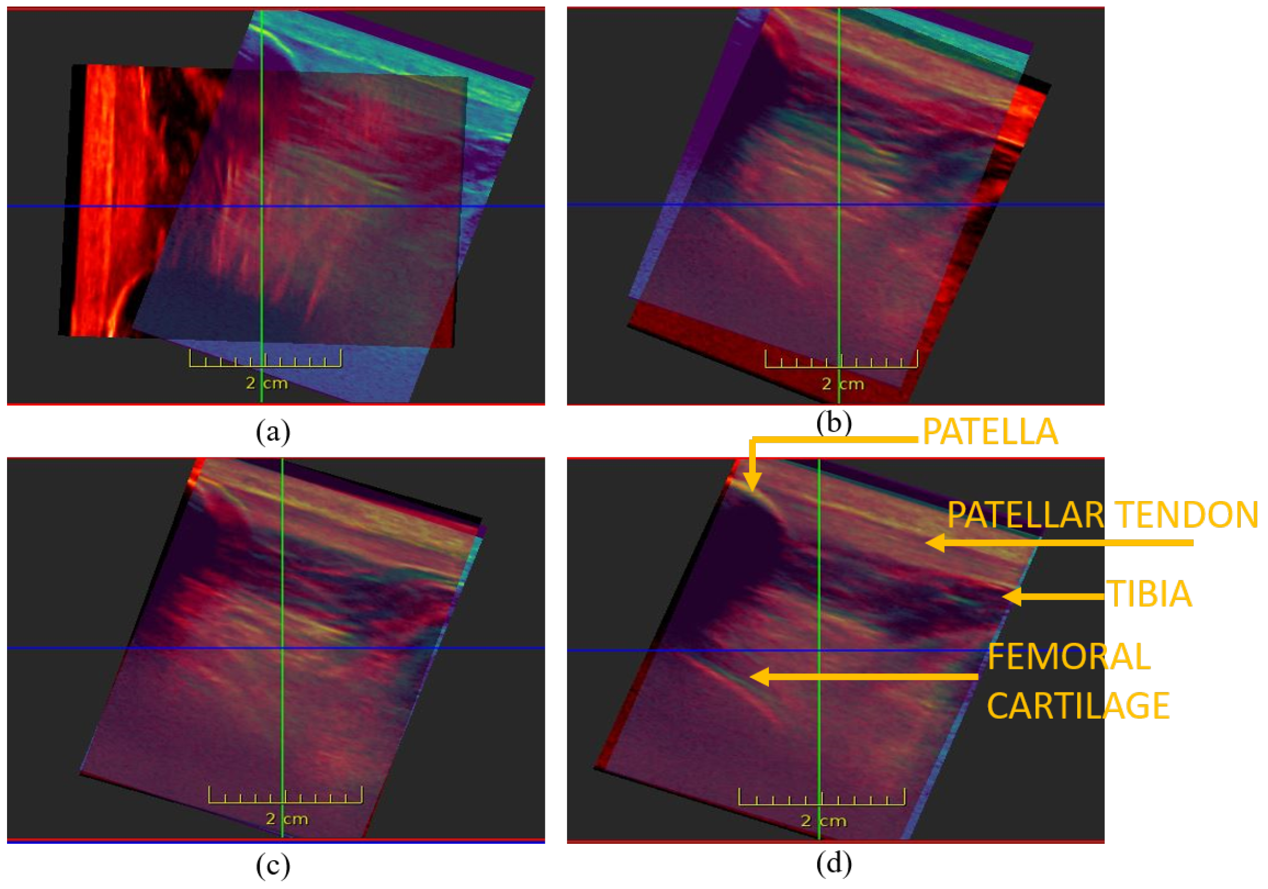
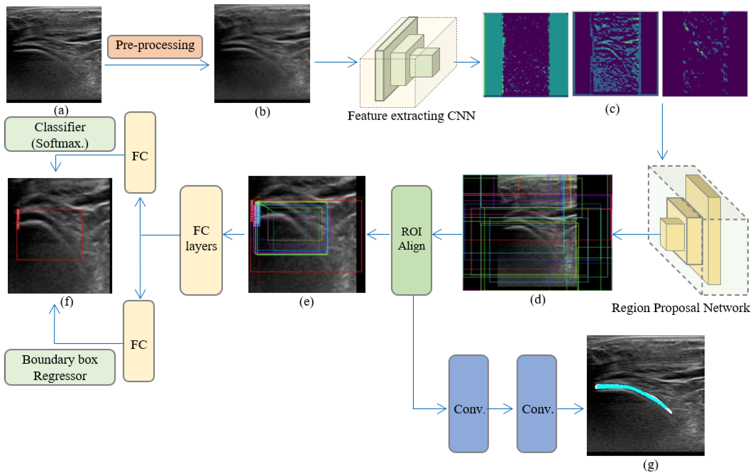
3.1. Segmentation
3.1.1. Segmentation of Femoral Cartilage from US
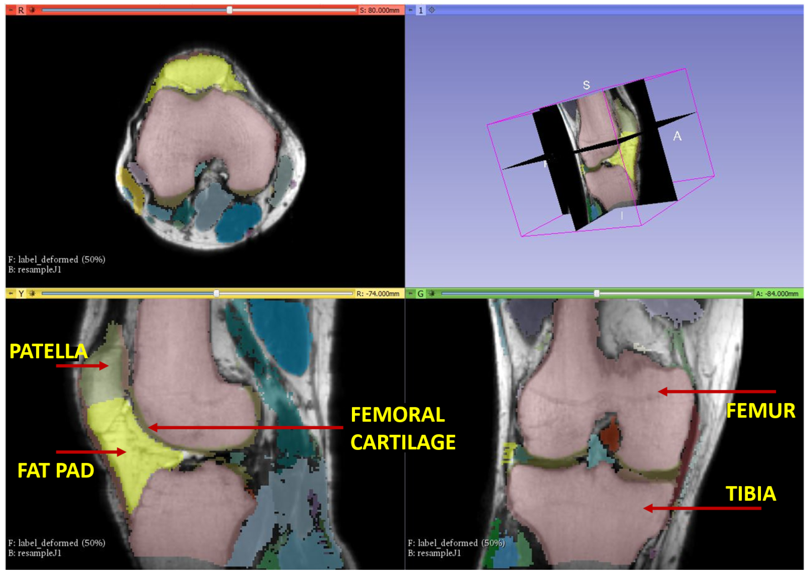
3.1.2. Segmentation of Femoral Cartilage from MRI
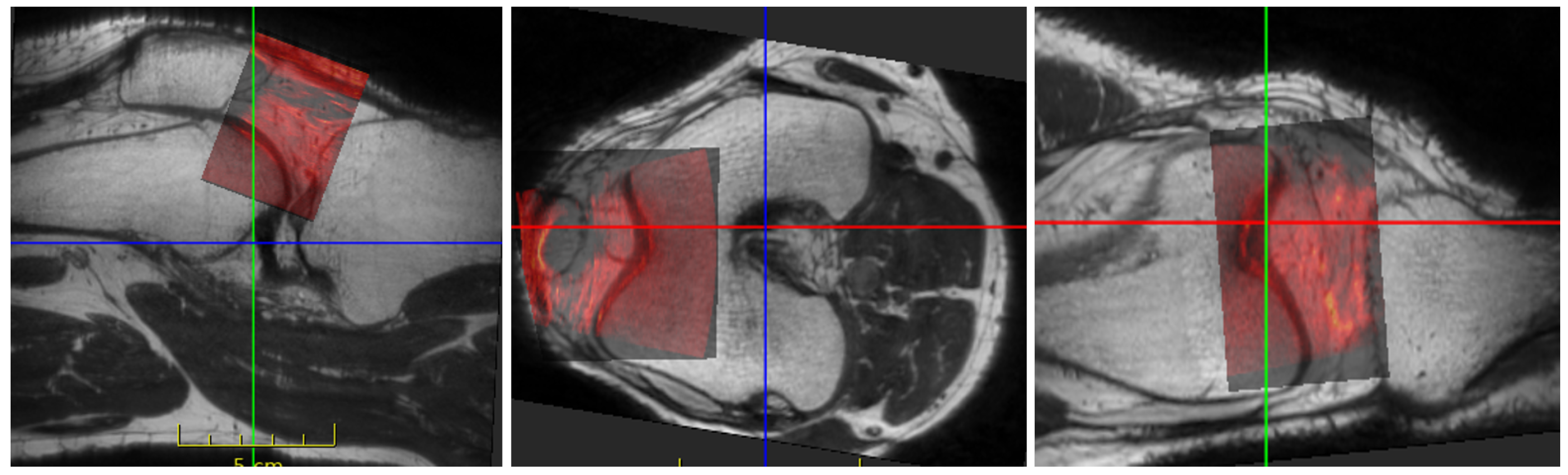
3.2. Registration
3.2.1. Data Pre-Processing
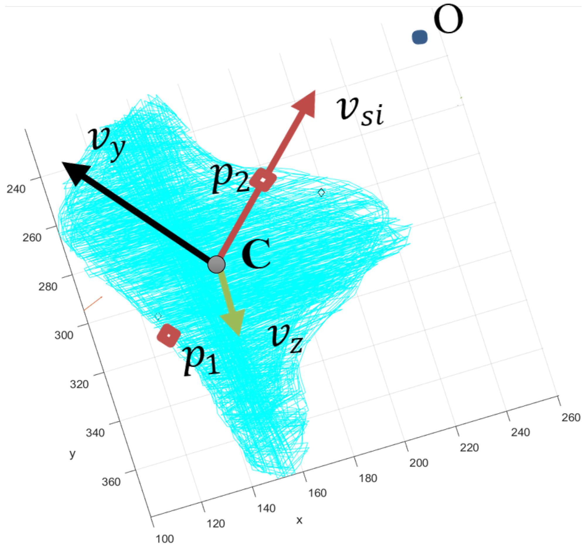
3.2.2. Pre-Initialization
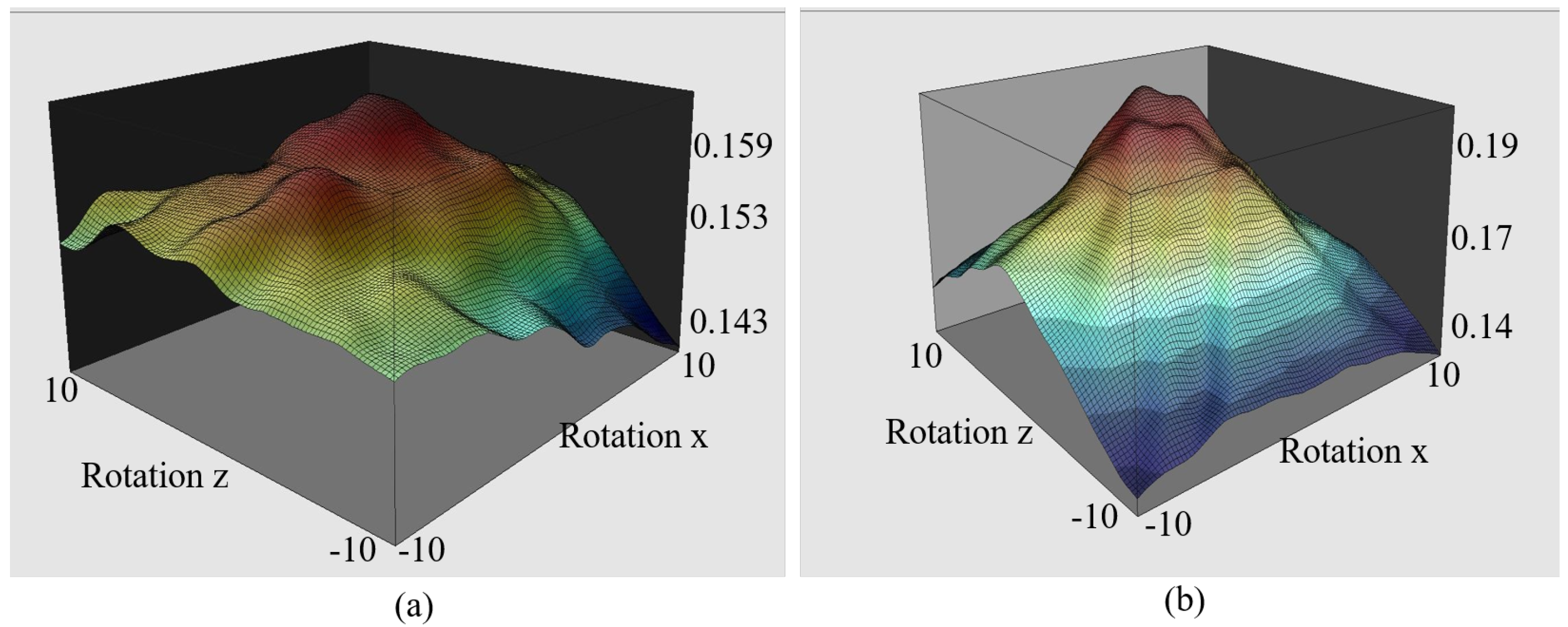
3.2.3. Initialization by Euclidean Distance Transform
3.2.4. Registration
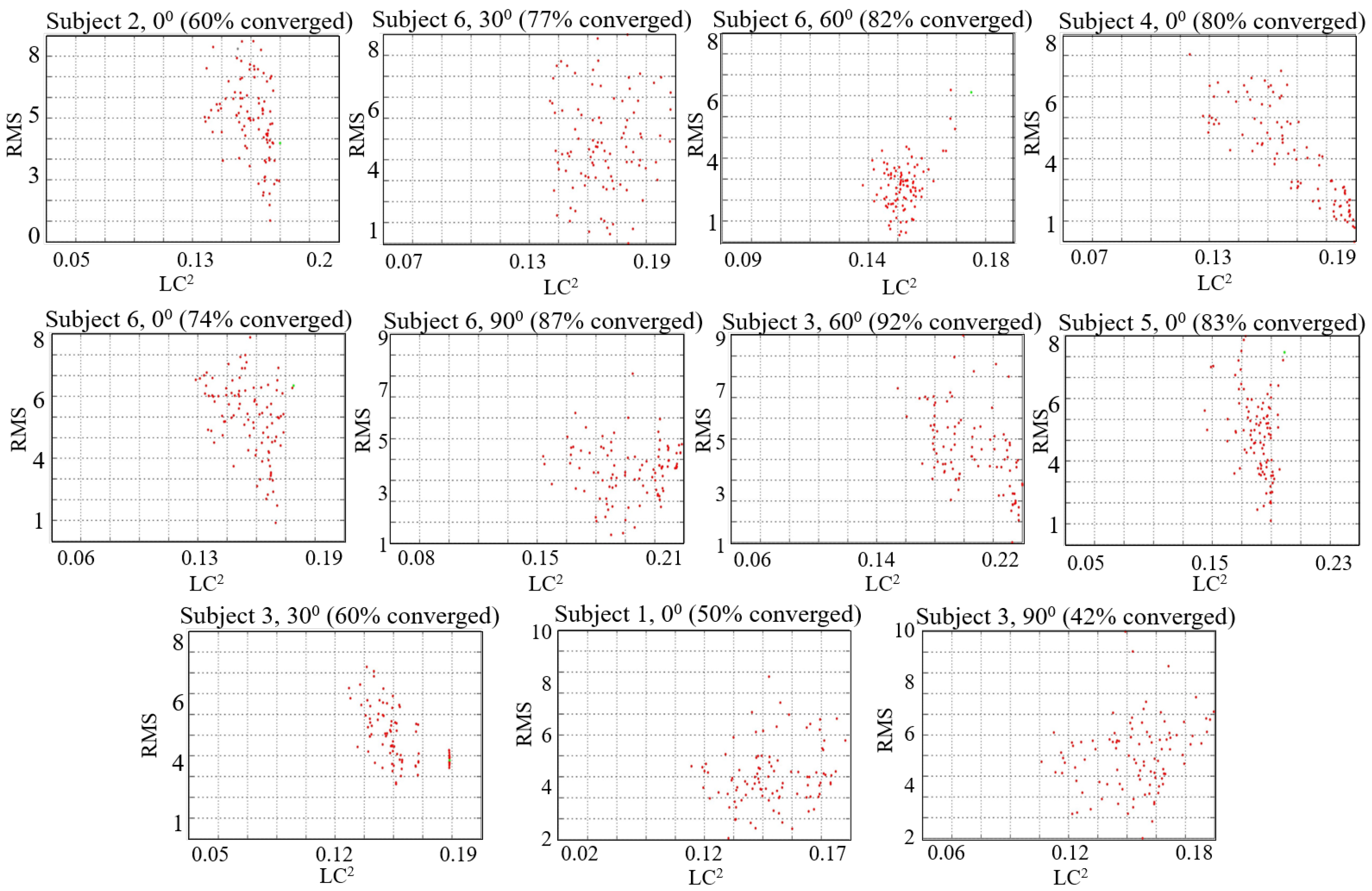
4. Results and Discussion
5. Conclusions
Author Contributions
Funding
Institutional Review Board Statement
Informed Consent Statement
Data Availability Statement
Acknowledgments
Conflicts of Interest
Appendix A. Segmentations
Appendix A.1. Segmentation of Femoral Cartilage from US

Appendix B. Pre-Initialization
References
- Schena, A.; Ross, G. Knee Arthroscopy: Technique and Normal Anatomy. In Knee Arthroscopy; Springer: New York, NY, USA, 2009; pp. 1–10. [Google Scholar] [CrossRef]
- Jaiprakash, A.; O’Callaghan, W.B.; Whitehouse, S.L.; Pandey, A.; Wu, L.; Roberts, J.; Crawford, R.W. Orthopaedic surgeon attitudes towards current limitations and the potential for robotic and technological innovation in arthroscopic surgery. J. Orthop. Surg. 2017, 25, 2309499016684993. [Google Scholar] [CrossRef] [PubMed]
- Price, A.J.; Erturan, G.; Akhtar, K.; Judge, A.; Alvand, A.; Rees, J.L. Evidence-based surgical training in orthopaedics. Bone Jt. J. 2015, 97-B, 1309–1315. [Google Scholar] [CrossRef]
- Banach, A.; Strydom, M.; Jaiprakash, A.; Carneiro, G.; Eriksson, A.; Crawford, R.; McFadyen, A. Visual Localisation for Knee Arthroscopy. Int. J. Comput. Assist. Radiol. Surg. 2021, 16, 2137–2145. [Google Scholar] [CrossRef] [PubMed]
- Wu, L.; Jaiprakash, A.; Pandey, A.K.; Fontanarosa, D.; Jonmohamadi, Y.; Antico, M.; Strydom, M.; Razjigaev, A.; Sasazawa, F.; Roberts, J.; et al. 29-Robotic and Image-Guided Knee Arthroscopy. In Handbook of Robotic and Image-Guided Surgery; Abedin-Nasab, M.H., Ed.; Elsevier: Amsterdam, The Netherlands, 2020; pp. 493–514. [Google Scholar] [CrossRef]
- Antico, M.; Sasazawa, F.; Wu, L.; Jaiprakash, A.; Roberts, J.; Crawford, R.; Pandey, A.K.; Fontanarosa, D. Ultrasound guidance in minimally invasive robotic procedures. Med. Image Anal. 2019, 54, 149–167. [Google Scholar] [CrossRef]
- Chopra, S.S.; Hünerbein, M.; Eulenstein, S.; Lange, T.; Schlag, P.M.; Beller, S. Development and validation of a three-dimensional ultrasound based navigation system for tumor resection. Eur. J. Surg. Oncol. 2008, 34, 456–461. [Google Scholar] [CrossRef]
- Kim, K.; Choi, H. High-efficiency high-voltage class F amplifier for high-frequency wireless ultrasound systems. PLoS ONE 2021, 16, e0249034. [Google Scholar] [CrossRef] [PubMed]
- Xiao, Y.; Fortin, M.; Unsgård, G.; Rivaz, H.; Reinertsen, I. REtroSpective Evaluation of Cerebral Tumors (RESECT): A clinical database of pre-operative MRI and intra-operative ultrasound in low-grade glioma surgeries. Med. Phys. 2017, 44, 3875–3882. [Google Scholar] [CrossRef] [PubMed] [Green Version]
- Xiao, Y.; Rivaz, H.; Chabanas, M.; Fortin, M.; Machado, I.; Ou, Y.; Heinrich, M.P.; Schnabel, J.A.; Zhong, X.; Maier, A.; et al. Evaluation of MRI to Ultrasound Registration Methods for Brain Shift Correction: The CuRIOUS2018 Challenge. IEEE Trans. Med. Imaging 2020, 39, 777–786. [Google Scholar] [CrossRef] [PubMed] [Green Version]
- Wein, W.; Ladikos, A.; Fuerst, B.; Shah, A.; Sharma, K.; Navab, N. Global Registration of Ultrasound to MRI Using the LC2 Metric for Enabling Neurosurgical Guidance. In Proceedings of the Medical Image Computing and Computer-Assisted Intervention—MICCAI 2013, Nagoya, Japan, 22–26 September 2013; Mori, K., Sakuma, I., Sato, Y., Barillot, C., Navab, N., Eds.; Springer: Berlin/Heidelberg, Germany, 2013; pp. 34–41. [Google Scholar] [CrossRef] [Green Version]
- Nitsch, J.; Klein, J.; Dammann, P.; Wrede, K.; Gembruch, O.; Moltz, J.; Meine, H.; Sure, U.; Kikinis, R.; Miller, D. Automatic and efficient MRI-US segmentations for improving intraoperative image fusion in image-guided neurosurgery. Neuroimage Clin. 2019, 22, 101766. [Google Scholar] [CrossRef] [PubMed]
- Huang, X.; Hill, N.A.; Ren, J.; Guiraudon, G.; Boughner, D.; Peters, T.M. Dynamic 3D Ultrasound and MR Image Registration of the Beating Heart. In Proceedings of the Medical Image Computing and Computer-Assisted Intervention—MICCAI 2005, Palm Springs, CA, USA, 26–29 October 2005; Duncan, J.S., Gerig, G., Eds.; Springer: Berlin/Heidelberg, Germany, 2005; pp. 171–178. [Google Scholar] [CrossRef] [Green Version]
- Penney, G.; Blackall, J.; Hamady, M.; Sabharwal, T.; Adam, A.; Hawkes, D. Registration of freehand 3D ultrasound and magnetic resonance liver images. Med. Image Anal. 2004, 8, 81–91. [Google Scholar] [CrossRef] [PubMed]
- Nigris, D.D.; Collins, D.L.; Arbel, T. Fast rigid registration of pre-operative magnetic resonance images to intra-operative ultrasound for neurosurgery based on high confidence gradient orientations. Int. J. Comput. Assist. Radiol. Surg. 2013, 8, 649–661. [Google Scholar] [CrossRef] [PubMed]
- Wein, W.; Brunke, S.; Khamene, A.; Callstrom, M.R.; Navab, N. Automatic CT-ultrasound registration for diagnostic imaging and image-guided intervention. Med. Image Anal. 2008, 12, 577–585. [Google Scholar] [CrossRef] [PubMed]
- Rackerseder, J.; Baust, M.; Göbl, R.; Navab, N.; Hennersperger, C. Initialize Globally Before Acting Locally: Enabling Landmark-Free 3D US to MRI Registration. In Proceedings of the Medical Image Computing and Computer Assisted Intervention—MICCAI 2018, Granada, Spain, 16–20 September 2018; Frangi, A.F., Schnabel, J.A., Davatzikos, C., Alberola-López, C., Fichtinger, G., Eds.; Springer International Publishing: Cham, Switzerland, 2018; pp. 827–835. [Google Scholar] [CrossRef] [Green Version]
- Fedorov, A.; Khallaghi, S.; Sánchez, C.A.; Lasso, A.; Fels, S.; Tuncali, K.; Sugar, E.N.; Kapur, T.; Zhang, C.; Wells, W.; et al. Open-source image registration for MRI–TRUS fusion-guided prostate interventions. Int. J. Comput. Assist. Radiol. Surg. 2015, 10, 925–934. [Google Scholar] [CrossRef] [PubMed] [Green Version]
- Slavcheva, M.; Kehl, W.; Navab, N.; Ilic, S. SDF-2-SDF: Highly Accurate 3D Object Reconstruction. In Proceedings of the Computer Vision—ECCV 2016, Amsterdam, The Netherlands, 11–14 October 2016; Leibe, B., Matas, J., Sebe, N., Welling, M., Eds.; Springer International Publishing: Cham, Switzerland, 2016; pp. 680–696. [Google Scholar] [CrossRef]
- Canalini, L.; Klein, J.; Miller, D.; Kikinis, R. Registration of Ultrasound Volumes Based on Euclidean Distance Transform. In Large-Scale Annotation of Biomedical Data and Expert Label Synthesis and Hardware Aware Learning for Medical Imaging and Computer Assisted Intervention; Zhou, L., Heller, N., Shi, Y., Xiao, Y., Sznitman, R., Cheplygina, V., Mateus, D., Trucco, E., Hu, X.S., Chen, D., et al., Eds.; Springer International Publishing: Cham, Switzerland, 2019; pp. 127–135. [Google Scholar] [CrossRef] [Green Version]
- Antico, M.; Sasazawa, F.; Takeda, Y.; Jaiprakash, A.T.; Wille, M.L.; Pandey, A.K.; Crawford, R.; Fontanarosa, D. 4D Ultrasound-Based Knee Joint Atlas for Robotic Knee Arthroscopy: A Feasibility Study. IEEE Access 2020, 8, 146331–146341. [Google Scholar] [CrossRef]
- He, K.; Gkioxari, G.; Dollár, P.; Girshick, R. Mask R-CNN. In Proceedings of the 2017 IEEE International Conference on Computer Vision (ICCV), Venice, Italy, 22–29 October 2017; pp. 2980–2988. [Google Scholar] [CrossRef]
- Kompella, G.; Antico, M.; Sasazawa, F.; Jeevakala, S.; Ram, K.; Fontanarosa, D.; Pandey, A.K.; Sivaprakasam, M. Segmentation of Femoral Cartilage from Knee Ultrasound Images Using Mask R-CNN. In Proceedings of the 2019 41st Annual International Conference of the IEEE Engineering in Medicine and Biology Society (EMBC), Berlin, Germany, 23–27 July 2019; pp. 966–969. [Google Scholar] [CrossRef] [Green Version]
- Richolt, J.; Jakab, M.; Kikinis, R. MRI-Based Atlas of the Knee; Technical Report; Surgical Planning Laboratory, Department of Radiology, Brigham and Women’s Hospital, Harvard Medical School: Boston, MA, USA, 2015. [Google Scholar]
- Avants, B.B.; Tustison, N.J.; Stauffer, M.; Song, G.; Wu, B.; Gee, J.C. The Insight ToolKit image registration framework. Front. Neuroinform. 2014, 8, 44. [Google Scholar] [CrossRef] [PubMed] [Green Version]
- Powell, M.J.D. The BOBYQA Algorithm for Bound Constrained Optimization without Derivatives; University of Cambridge: Cambridge, UK, 2009. [Google Scholar]
- Vaarkamp, J. Reproducibility of interactive registration of 3D CT and MR pediatric treatment planning head images. J. Appl. Clin. Med. Phys. 2001, 2, 131–137. [Google Scholar] [CrossRef] [PubMed]


| 0 | 30 | 60 | 90 |
|---|---|---|---|
| Volunteer 1 | Volunteer 3 | Volunteer 3 | Volunteer 3 |
| Volunteer 2 | Volunteer 6 | Volunteer 6 | Volunteer 6 |
| Volunteer 4 | |||
| Volunteer 5 | |||
| Volunteer 6 |
| Angle | Patient No. | Translation Error (mm) | Rotation Error () | Final Error(t,r) | ||||||
|---|---|---|---|---|---|---|---|---|---|---|
| In-Err | Pre-in | DT | LC | In-Err | Pre-in | DT | LC | |||
| 0 | Subject 1 | 34.72 | 9.83 | 6.04 | 2.00 | 73.70 | 20.13 | 28.67 | 5.50 | 2.00 mm, 5.50 |
| 0 | Subject 2 | 35.39 | 10.59 | 14.62 | 3.94 | 62.14 | 21.01 | 14.47 | 8.78 | 3.94 mm, 8.78 |
| 0 | Subject 4 | 39.10 | 13.45 | 2.67 | 1.72 | 60.28 | 8.94 | 4.93 | 3.91 | 1.72 mm, 3.91 |
| 0 | Subject 5 | 32.09 | 7.43 | 3.88 | 1.47 | 65.88 | 13.29 | 17.26 | 4.15 | 1.47 mm, 4.15 |
| 0 | Subject 6 | 31.68 | 11.04 | 17.74 | 2.43 | 67.83 | 33.15 | 13.41 | 8.67 | 2.43 mm, 8.67 |
| 30 | Subject 3 | 26.14 | 12.05 | 1.43 | 1.41 | 45.37 | 32.13 | 2.41 | 2.34 | 1.41 mm, 2.34 |
| 30 | Subject 6 | 31.89 | 30.06 | 9.19 | 4.80 | 25.88 | 35.29 | 12.56 | 9.03 | 4.80 mm, 9.03 |
| 60 | Subject 3 | 27.99 | 17.75 | 8.70 | 5.09 | 55.21 | 7.81 | 15.80 | 6.43 | 5.09 mm, 6.43 |
| 60 | Subject 6 | 27.71 | 7.49 | 7.45 | 6.00 | 27.94 | 18.70 | 9.70 | 5.80 | 6.00 mm, 5.80 |
| 90 | Subject 3 | 33.13 | 22.79 | 5.36 | 3.63 | 25.82 | 33.29 | 26.46 | 15.07 | 3.63 mm, 15.07 |
| 90 | Subject 6 | 34.50 | 12.15 | 3.58 | 6.03 | 25.09 | 12.53 | 17.62 | 16.04 | 6.03 mm, 16.04 |
| Angle | Subject | Translation | Rotation |
|---|---|---|---|
| 0 | Subject 3 | 3.00 mm | 4.12 |
| 0 | Subject 5 | 3.89 mm | 6.51 |
| 0 | Subject 6 | 4.63 mm | 9.24 |
| 30 | Subject 6 | 3.64 mm | 4.05 |
| 60 | Subject 3 | 7.94 mm | 9.06 |
| 60 | Subject 6 | 1.67 mm | 11.99 |
| 90 | Subject 3 | 4.77 mm | 9.84 |
| 90 | Subject 6 | 5.80 mm | 7.28 |
Publisher’s Note: MDPI stays neutral with regard to jurisdictional claims in published maps and institutional affiliations. |
© 2022 by the authors. Licensee MDPI, Basel, Switzerland. This article is an open access article distributed under the terms and conditions of the Creative Commons Attribution (CC BY) license (https://creativecommons.org/licenses/by/4.0/).
Share and Cite
Kompella, G.; Singarayan, J.; Antico, M.; Sasazawa, F.; Yu, T.; Ram, K.; Pandey, A.K.; Fontanarosa, D.; Sivaprakasam, M. Automatic 3D MRI-Ultrasound Registration for Image Guided Arthroscopy. Appl. Sci. 2022, 12, 5488. https://0-doi-org.brum.beds.ac.uk/10.3390/app12115488
Kompella G, Singarayan J, Antico M, Sasazawa F, Yu T, Ram K, Pandey AK, Fontanarosa D, Sivaprakasam M. Automatic 3D MRI-Ultrasound Registration for Image Guided Arthroscopy. Applied Sciences. 2022; 12(11):5488. https://0-doi-org.brum.beds.ac.uk/10.3390/app12115488
Chicago/Turabian StyleKompella, Gayatri, Jeevakala Singarayan, Maria Antico, Fumio Sasazawa, Takeda Yu, Keerthi Ram, Ajay K. Pandey, Davide Fontanarosa, and Mohanasankar Sivaprakasam. 2022. "Automatic 3D MRI-Ultrasound Registration for Image Guided Arthroscopy" Applied Sciences 12, no. 11: 5488. https://0-doi-org.brum.beds.ac.uk/10.3390/app12115488