
Simulation-Based Selection of Transmitting Antenna Type for Enhanced Loran System in Selected Location


1
National Time Service Centre, Chinese Academy of Sciences, Xi’an 710600, China
2
Beijing Institute of Tracking and Telecommunications Technology, Beijing 100094, China
*
Authors to whom correspondence should be addressed.
Appl. Sci. 2022, 12(12), 6031; https://0-doi-org.brum.beds.ac.uk/10.3390/app12126031
Submission received: 19 April 2022
/
Revised: 2 June 2022
/
Accepted: 9 June 2022
/
Published: 14 June 2022
(This article belongs to the Special Issue Design, Analysis, and Measurement of Antennas)
Abstract
:To improve the coverage and timing capability of enhanced Loran signals, three enhanced Loran transmitters are planned to be built in Western China. The most appropriate antenna configuration can be determined by comparing domestic and foreign mainstream small and radio antennas. By analyzing and comparing the electrical and structural parameters and signal propagation curves of the transmitting antenna, it can be concluded that the single tower umbrella antenna provides the best performance in all evaluation indexes, and the enhanced Loran signal can be transmitted to areas 1000 km away through the single tower umbrella antenna so that the enhanced Loran signal covers most areas of Western China. Therefore, it should be widely used in the construction of enhanced Loran transmitters in the future.
1. Introduction
The enhanced Loran system evolved from the Loran-C (long-range navigation) system. It is an internationally standardized positioning, navigation and timing (pnt) service system. It is the latest development achievement of low-frequency long-range radio navigation timing technology. It meets the needs of PNT services in aviation non-precision approach, port approach, land vehicle navigation and location service in terms of PNT service accuracy, reliability, effectiveness, perfection and continuity. Additionally, it can provide high-precision time and frequency signals in the order of hundreds of nanoseconds. The eLoran transmitting antenna is an important part of the system; its electrical performance and coverage ability are very important [1,2,3].
Loran transmitting antennas are a mature technology has that has benefitted from many years of research and development. Typically, they comprise single-tower umbrella antennas or four-tower inverted cone antennas [4,5].
China plans to build three enhanced Loran launchers in the western region. Its purpose is to cover most parts of China with Loran time service signal, which will be used for time service and navigation in the future. At present, the performance of the Loran-C system in all aspects of operation is relatively backward. Therefore, the three new transmitting stations will choose the Loran transmitting antenna with higher performance. In particular, the Tibet Naqu transmitting station, one of the three largest transmitting stations, will realize the construction of Loran transmitting antennas for the first time in regions above 4500 m above sea level in the world. Referring to the past design and construction experience of Loran transmitting antennas, it is difficult to meet the current needs. Therefore, the design and selection of the transmitting antenna will face new challenges. The antenna not only needs to cope with the complex geographical characteristics of Tibet, but also needs to meet the requirements of the transmitter and improve the signal radiation capacity as much as possible, which will put forward higher requirements for the structural and electrical performance design of the transmitting antenna. Its main purpose is to carry the signal transmitted by a 2500 kW high-power transmitter and radiate it efficiently. The radiation efficiency is more than 70%. It is planned to cover most of the land area in Western China. The main performance requirements are as follows: (1) the working center frequency is 100 kHz; (2) The bandwidth exceeds 3.5 kHz; (3) The effective height exceeds 180 m; (4) The characteristic impedance is 200–300 Ω [6,7].
2. International Typical Transmitting Antenna Reference
2.1. China
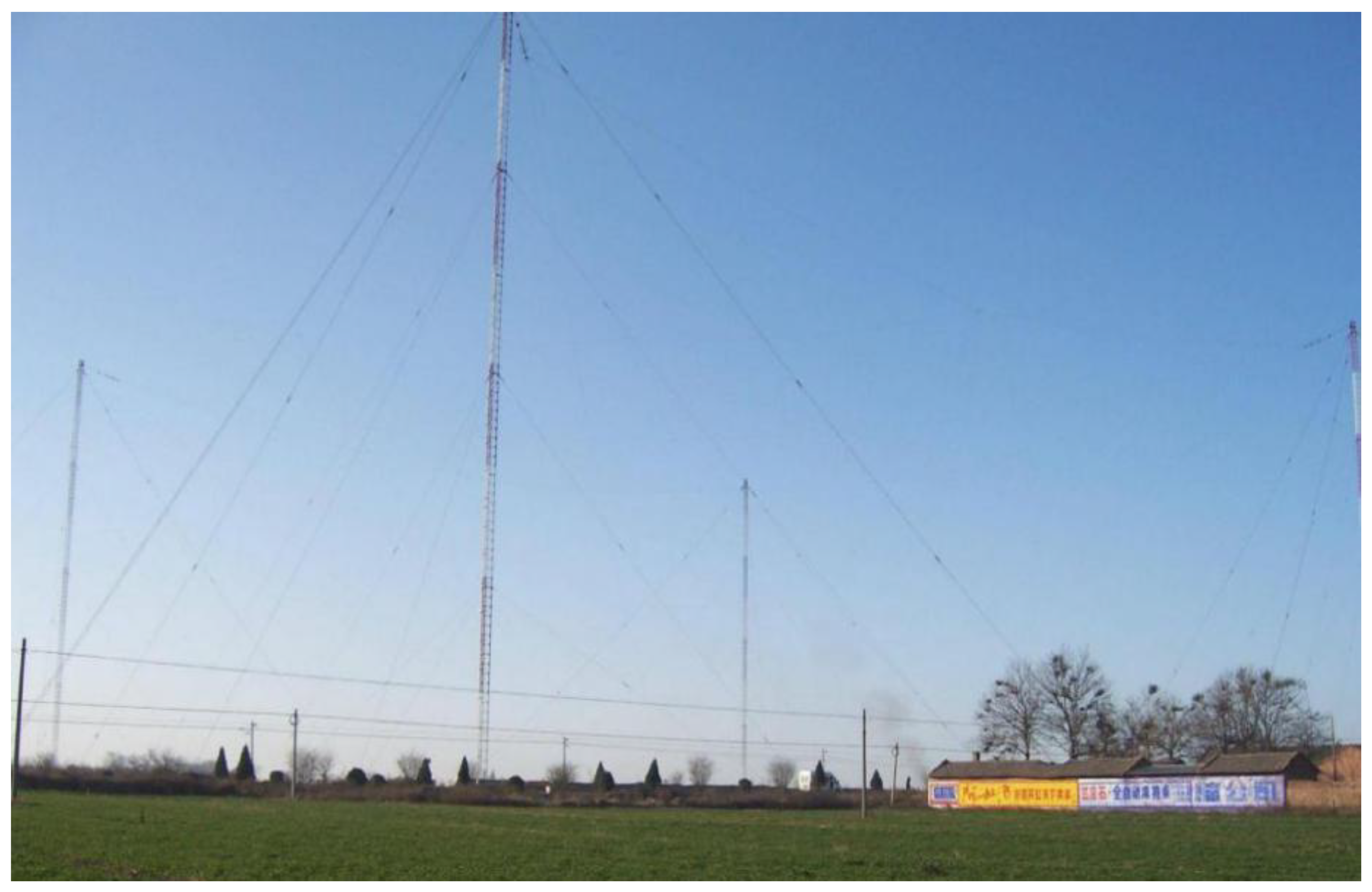
The BPL long-wave timing station is located in Pucheng County, Weinan City, Shaanxi Province. It is the first large-scale radio station in China to transmit and broadcast high-precision time standard signals. The transmitting antenna adopts the form of four inverted-cone antennas. It is supported by four towers with a height of approximately 206 m. The distance between the sides of the grounding tower is approximately 425 m. Figure 1 shows photos of the four towers of the BPL antenna [1,2].
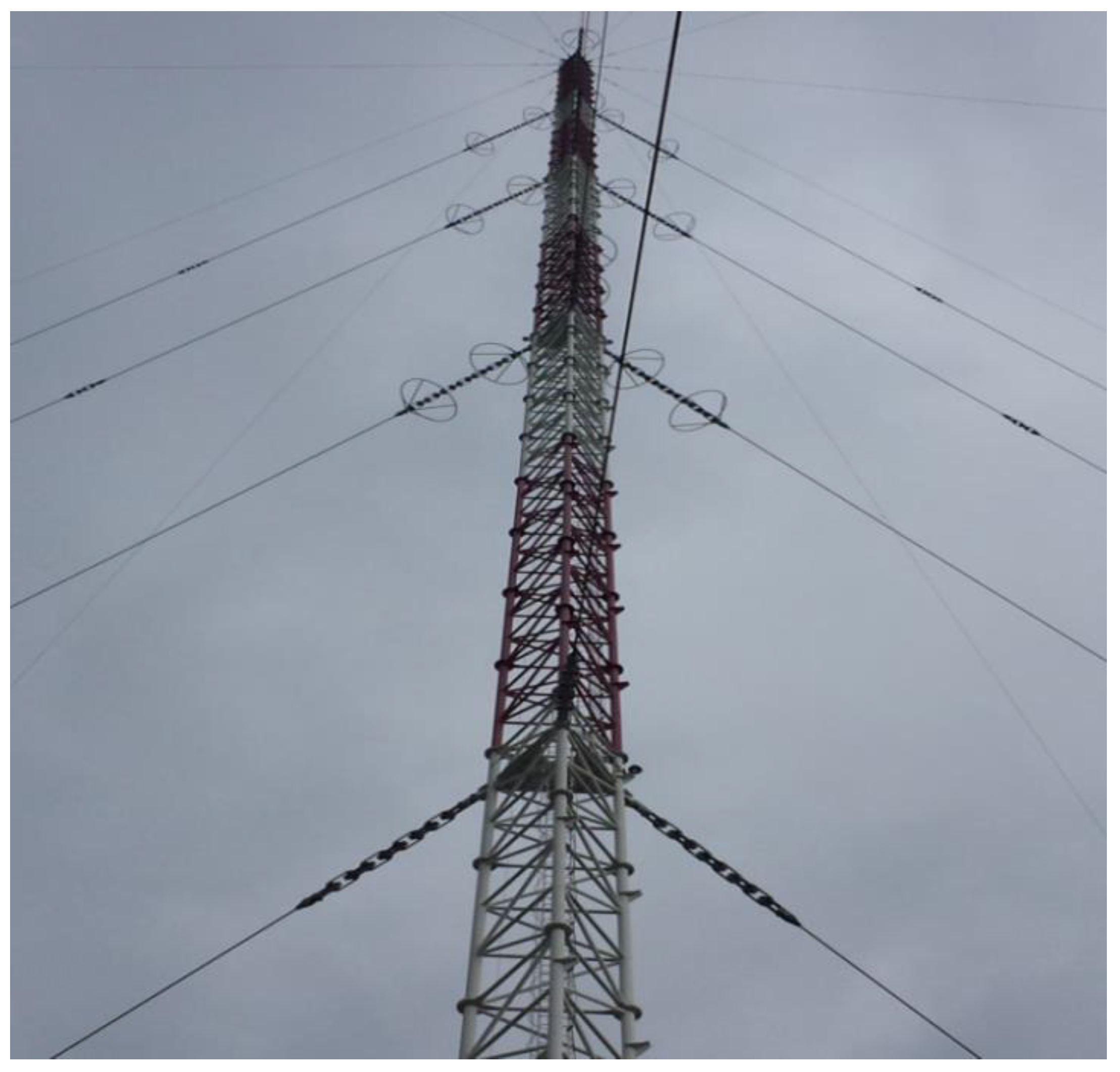
The Changhe II system, which has the form of a single-tower, insulated umbrella tower (see Figure 2), is located in Jilin Helong, Shandong Rongcheng, Anhui Xuancheng, Guangdong Raoping, Guangxi He County, and Chongzuo City. Single-tower umbrella antennas are geometrically symmetric, which can improve the efficiency of the ground net and thus the system transmission efficiency. The horizontal component of the single antenna is small, which reduces the energy loss of the antenna system and the interference of the horizontal component with the waveform [2,3].
2.2. United States
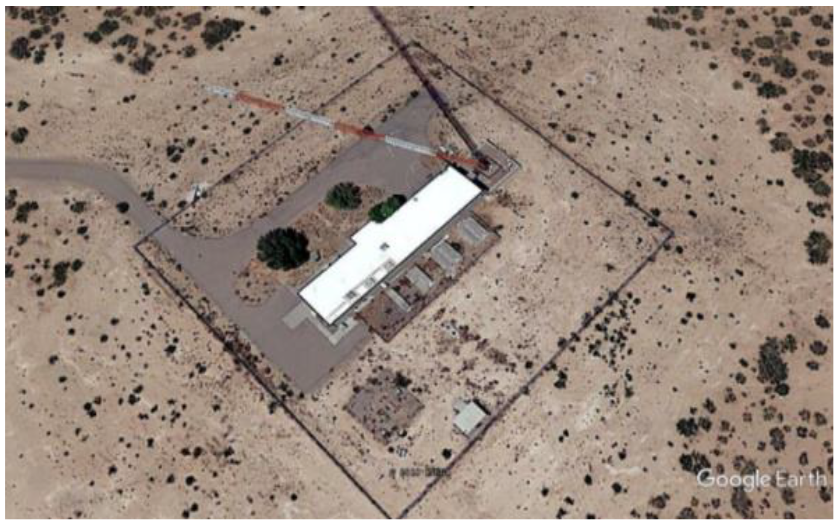
There are many Loran-C transmitting antennas in the USA. Most use tall mast radiators with heights ranging from 190–220 m, which are insulated from the ground. These masts are inductively lengthened and fed by a loading coil. A well-known example of a station that uses such an antenna is Rantum. However, some stations utilize free-standing tower radiators of a similar height (e.g., Carolina Beach). The output power from some Loran-C transmitters exceeds 1000 kW, which is achieved by using extremely tall (412 m) mast radiators. Other high-power Loran-C stations, such as George, use four T-antennas mounted on four guyed masts arranged in a square configuration. Figure 3 shows a single-tower antenna belonging to a radio station in the USA, which is still used for the Loran-C system.
2.3. Russia
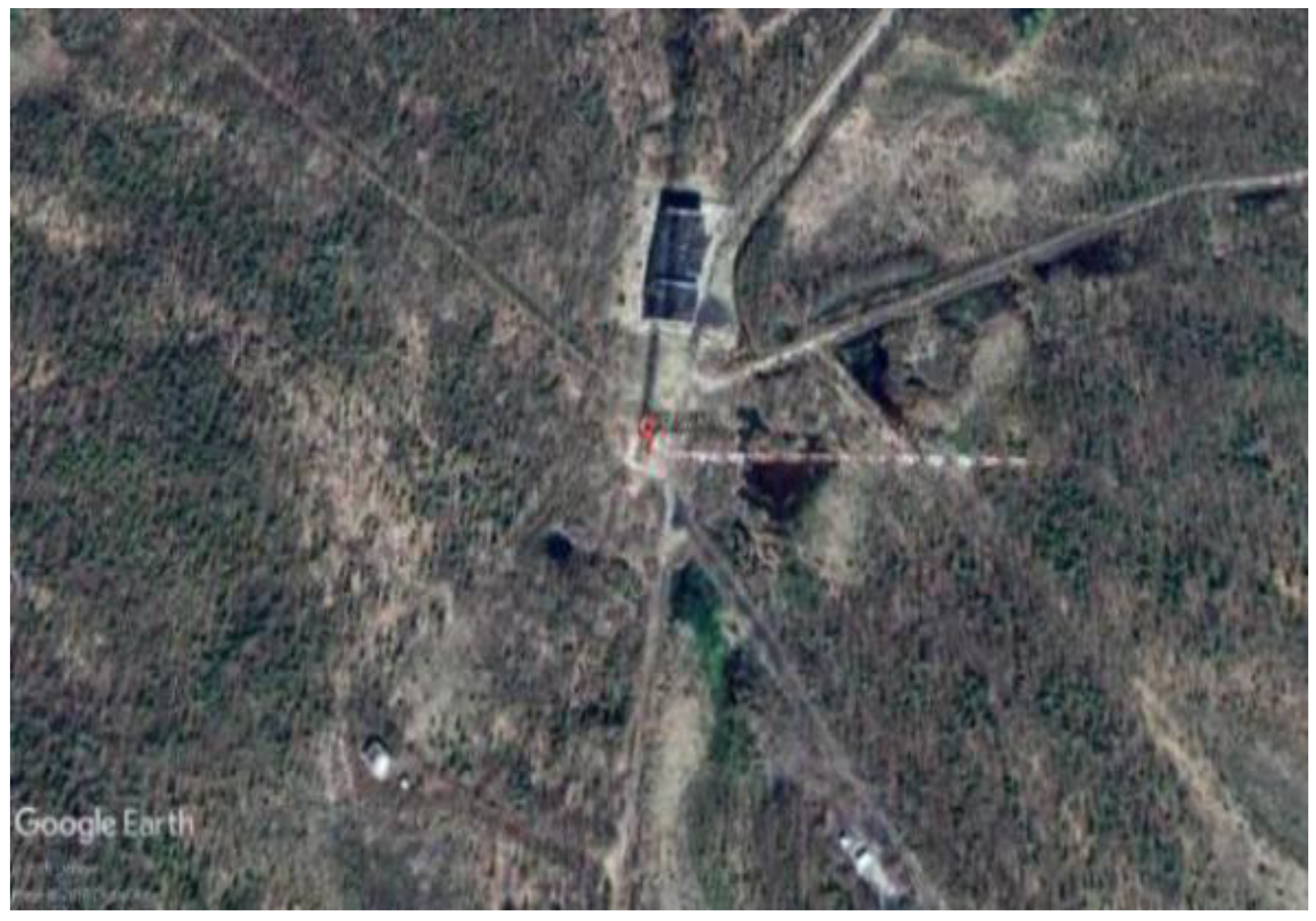
The Chayka system is a Russian ground radio navigation system that shares similarities with the Loran-C system. Chayka transmitters operate at very high power. Certain transmitters use 460 m tall, single-tower mast antenna, while others use multi-tower antennas. In the 1980s, three sets of transmission antennas were constructed as Chayka chains in northern Siberia. These chains were used to transmit 1200 kW navigation signals at 100 kHz and demonstrated high transmission efficiency. Figure 4 shows the 460-m-tall antennas used in the Russian Chayka system.
3. Structure and Performance Design of Typical Loran-C Transmitting Antenna
3.1. Single-Tower Antenna Form
As the main antenna form of the global Loran-C transmission system, the single tower antenna is usually an umbrella antenna supported by a 200–300 m high tower. The radiator is composed of mast, top line and bottom lead. Part of the top line below the line leads to the lower line at the bottom of the tower feed point. The whole radiator is in a conical umbrella shape. The representative schematic diagram of the structure is shown in Figure 5. The top of the tower is powered by several load top conductors as umbrella conductors, which are connected to the ground through insulators, and the bottom of the mast is connected to the ground through an insulator base. The radiation grounding grid is set with the iron tower as the center, and the ground wire is buried underground. The transmission power of the system is 2000 kW. Table 1 shows the performance indexes of the one-tower transmitting antennas designed with reference to Figure 5 at different heights [8,9].
![Applsci 12 06031 g005]()
Figure 5.
Schematic diagram of a single-tower umbrella antenna model.


Table 1.
Main Performance Parameters of the Single-Tower Antenna.
| The height of Single-Tower Antenna (m) | 280 | 250 | 200 |
| Antenna efficiency (%) | 78.2 | 77.2 | 70.61 |
| Input resistance (Ω) | 8.09 | 6.4 | 3.84 |
| Ground Loss Resistor (Ω) | 1.76 | 1.44 | 1.13 |
| Static capacitance (nF) | 7.57 | 7.25 | 5.79 |
| Antenna bandwidth (kHz) | 3.84 | 3.0 | 1.42 |
| Product of efficiency and bandwidth (kHz) | 3.0 | 2.33 | 1 |
| Effective height (m) | 189 | 168.1 | 124.4 |
The main advantages of the single tower umbrella antenna are that the main body of the antenna system is supported by only one iron tower, the antenna structure is relatively simple, the radiation efficiency is high, the engineering quantity is relatively small, the cost is low and the cost performance is high. Its main disadvantages are that the central tower needs to be insulated from the ground, the performance requirements of the base insulator are very high and the seismic performance of the system is lower than that of the four-tower inverted cone antenna. In addition, in areas prone to snow disasters and sand storms, there may be the risk of system short circuits and work interruption caused by the inundation of the base insulator.
3.2. Four-Tower Antenna Form
The antenna is supported by four towers of equal height between 200 and 280 m. The radiating body consists of a square top load, main and lower leads and auxiliary lower leads. A small tower is built at the center of the lower leads to provide fixed closure. A schematic diagram of the four-tower inverted-cone antenna is shown in Figure 6. Owing to the low effective height and radiation resistance of the four-tower inverted-cone antenna, a large-scale ground network needs to be designed to achieve better radiation efficiency. The ground network is radial with the feeding point as its center, which is also buried underground. Table 2 shows the performance indexes of the four-tower transmitting antennas designed with reference to Figure 6 at different heights [10,11].
![Applsci 12 06031 g006]()
Figure 6.
Schematic diagram of the four-tower inverted-cone antenna model.

Table 2.
Main Performance Parameters of the four-tower Antenna.
| The height of four-Towers Antenna (m) | 240 | 220 | 200 |
| Tower spacing (m) | 507.6 | 465.3 | 423 |
| Antenna efficiency (%) | 68.5 | 63.6 | 58.1 |
| Ground loss resistor (Ω) | 1.8 | 1.8 | 1.8 |
| Static capacitance (nF) | 37.48 | 34.49 | 31.6 |
| Radiation resistance (Ω) | 3.91 | 3.14 | 2.5 |
| Antenna bandwidth (kHz) | 13.46 | 10.72 | 8.54 |
| Product of efficiency and bandwidth (kHz) | 9.22 | 6.82 | 4.97 |
| Effective height (m) | 149.37 | 133.88 | 119.37 |
The main advantage of the four-tower transmitting antenna is that the tower height is relatively low and the bandwidth is wide. All iron towers are directly grounded to avoid the use of an insulator at the base of the iron tower. In areas with severe environments such as multiple snow disasters and earthquakes, the system has high safety, reliability and good seismic performance. Its main shortcomings are relatively low radiation efficiency, a large number of towers, large quantities and high cost.
4. Antenna Broadcast Signal Propagation Model
According to the atmospheric noise data in the book, VLF Radio Engineering of the United States, in Tibet, the maximum atmospheric noise affecting the 100-kHz frequency band occurs during summer, and the maximum noise spectral density is approximately −120 dBV∙m−1∙Hz1/2. The receiver bandwidth is 30 kHz (referring to the Loran-C receiver), which corresponds to a noise field strength of 44.7 dB∙μV∙m−1. Based on the operation experience of the long-running Loran-C navigation and BPL time service systems, a minimum signal field strength of 45 dB∙μV∙m−1 should be maintained to ensure reliable reception [12,13].
With reference to the geographic information data in four directions around the newly-built transmitter, setting the Loran signal propagation model and then simulating the transmission field strength of the antenna with MATLAB tools allows valuable data related to the terrain and signal propagation around the station to be obtained, which can be used to determine the propagation capacity and radiation efficiency requirements of the antenna.
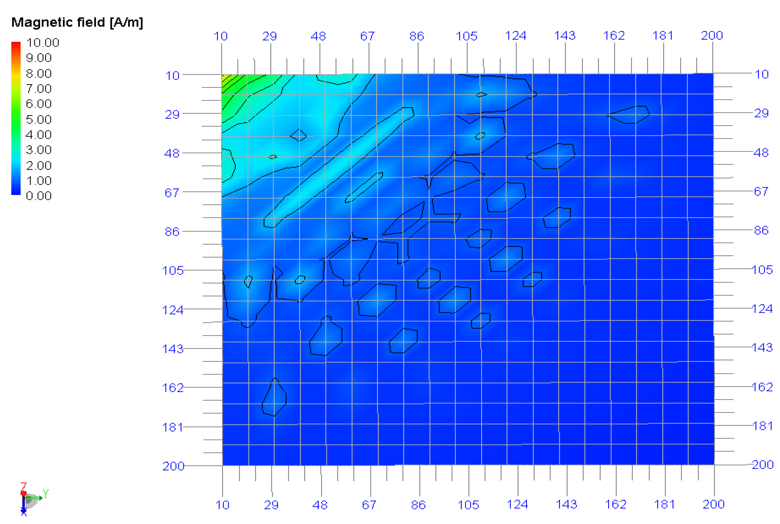
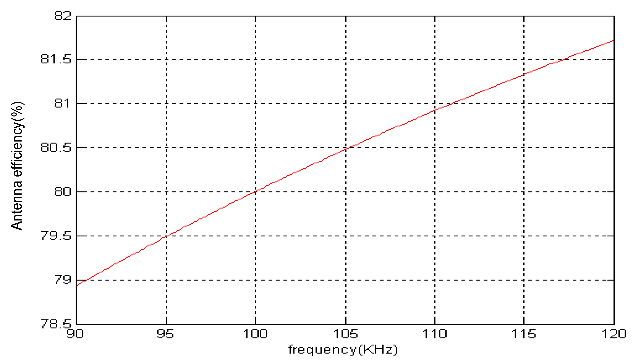
By comparing the structure and electrical performance of single-tower antennas and four-tower antennas, it can be seen that single-tower transmitting antennas have certain performance advantages. In order to further analyze the transmission capacity of a single-tower antenna, the antenna performance can be more directly understood from the aspects of the single-tower transmitting antenna pattern, the field intensity distribution under the antenna, the antenna magnetic field distribution and the radiation efficiency curve. Figure 7 shows the direction diagram of a single-tower antenna, Figure 8 shows the distribution of antenna field strength in the quarter area, Figure 9 shows the distribution of antenna magnetic field in the quarter area and Figure 10 shows the radiation efficiency curve.
With reference to the geographic information data in four directions around the newly-built transmitter, setting the Loran signal propagation model, and then simulating the transmission field strength of the antenna with MATLAB tools allows valuable data related to the terrain and signal propagation around the station to be obtained, which can be used to determine the propagation capacity and radiation efficiency requirements of the antenna. Therefore, an antenna selection database can be established. Simulating the four-way radio signal propagation around the transmitter in Naqu, Tibet is to finally determine the electrical parameters of the transmitting antenna and better deal with the very special geological and environmental conditions in Naqu, Tibet [14,15].
4.1. Eastward Transmission
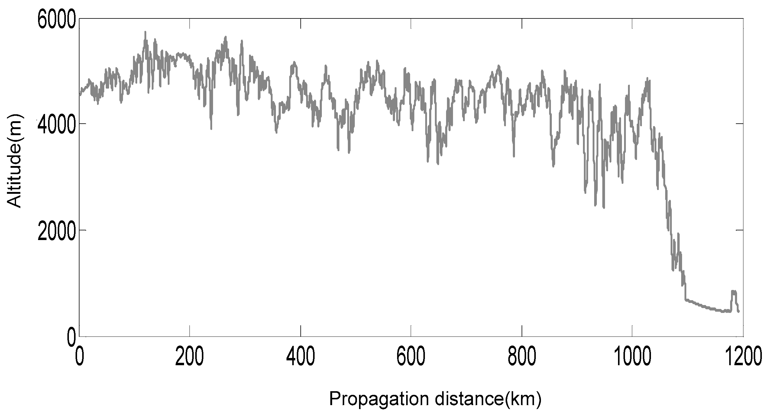
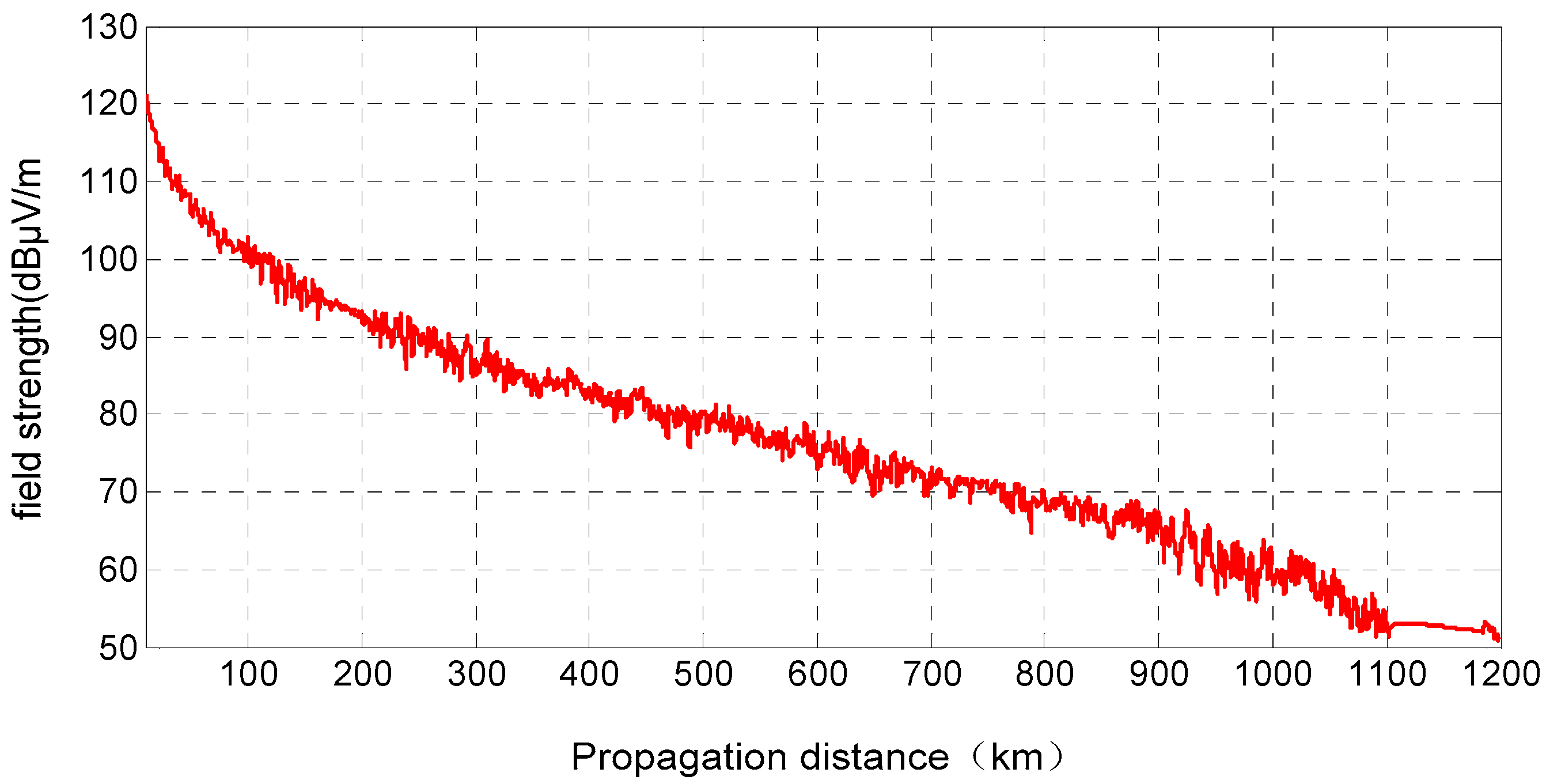
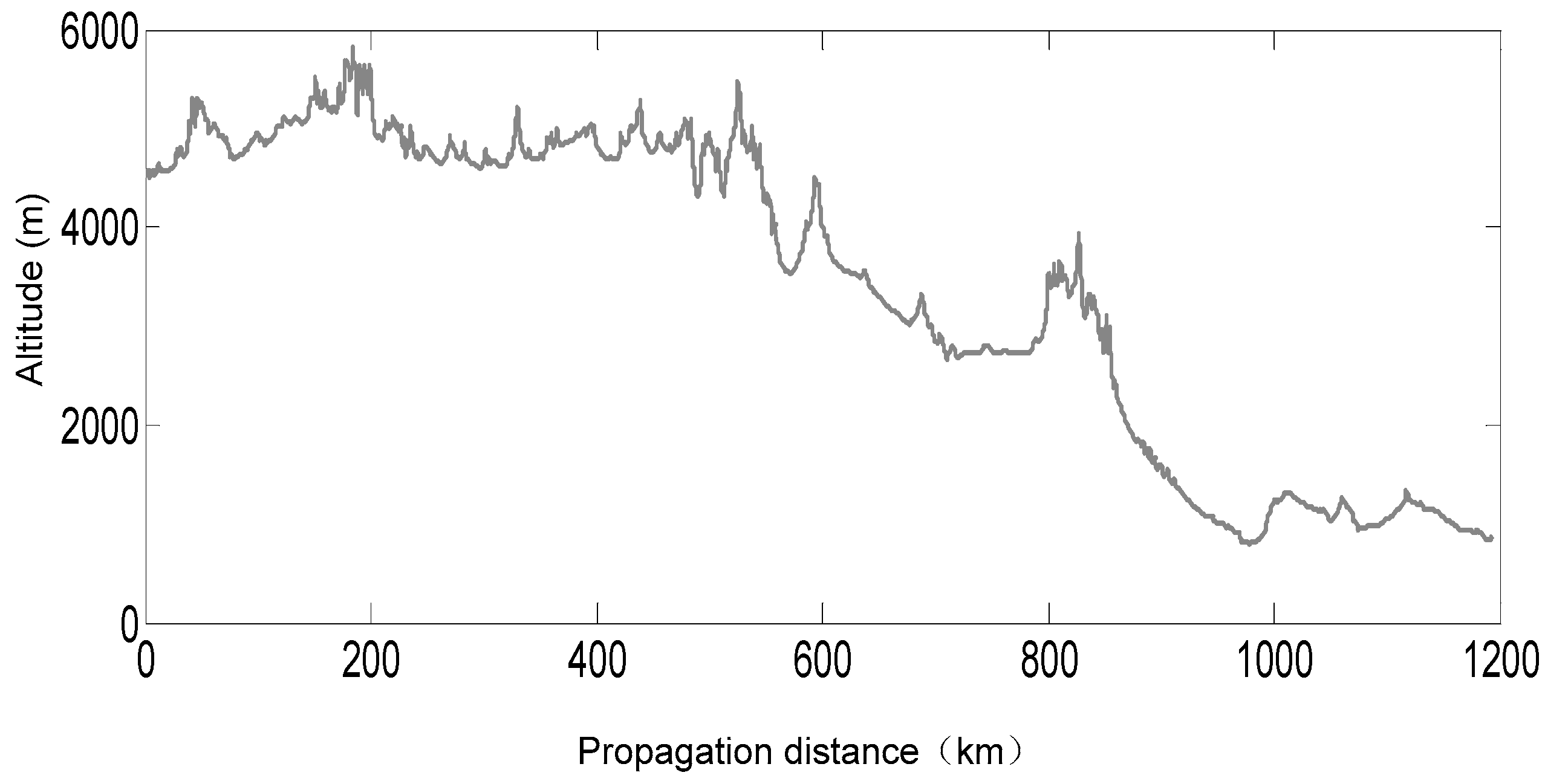
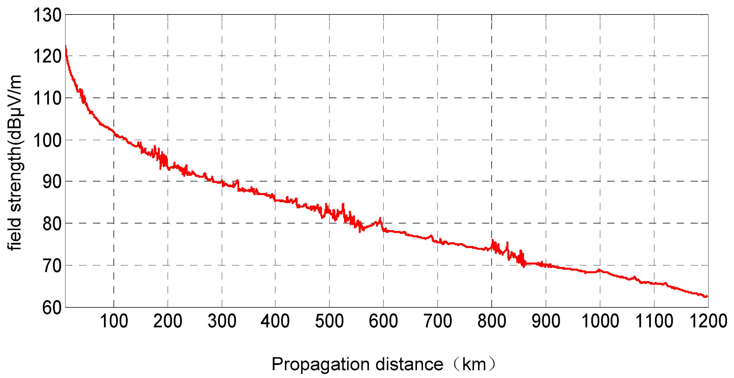
During the eastward propagation of the eLoran signal, the field strength of the signal will be affected by the terrain and change accordingly. Simulation Figure 11 shows the change of geographical environment during propagation, while Figure 12 shows that the signal field strength changes with the increase in propagation distance under the influence of geographical environment.
4.2. Westward Transmission
During the westward propagation of the eLoran signal, the field strength of the signal will be affected by the terrain and change accordingly. Simulation Figure 13 shows the change of geographical environment in the process of propagation, while Figure 14 shows the change of signal field strength under the influence of geographical environment with the increase in propagation distance.
4.3. Southward Transmission
When the eLoran signal propagates southward, the field strength of the signal will be affected by the terrain and change accordingly. Simulation Figure 15 shows the change of geographical environment during propagation, while Figure 16 shows that the signal field strength changes with the increase in propagation distance under the influence of geographical environment.
4.4. Northward Transmission
When the eLoran signal propagates northward, the field strength of the signal will be affected by the terrain and change accordingly. Simulation Figure 17 shows the change of geographical environment during propagation, while Figure 18 shows that the signal field strength changes with the increase in propagation distance under the influence of geographical environment.
The simulation results show that the topographic fluctuation of the propagation path has a slight influence on the signal intensity, with the propagation curves showing localized fading characteristics that correspond to the topographic profile. When the topographic fluctuations are less intense, the characteristics of the ground wave propagation decline are not as significant; only a few peaks demonstrate declines measuring 2–3 dB. The results indicate that the radiation signal field intensity of the Naqu transmitter can satisfy the required coverage distance of 1000 km. Furthermore, these results can be used to guide antenna construction in Western China. The results here demonstrate clearly that single-tower antennas with an increased effective height provide the optimal transmission range and efficiency [16,17,18].
5. Conclusions
Long-wave transmitting antennas have been widely used all over the world. Single-tower or four-tower structures are usually adopted. According to the development status of long-wave, high-power antenna technology at home and abroad, and referring to the practical experience of major Loran transmitting antennas in the world, the performance parameters of various Loran transmitting systems are compared. In addition, there are many innovations in the research work of this paper: firstly, this project will design and construct the Loran transmitting antenna with an altitude of more than 4500 m for the first time in the world. In addition, according to the geographical environment of the Naqu area, the propagation model of the Loran signal is established. Compared with previous papers, the innovations of this paper are shown in the content of this paper to have been rarely carried out before. Compared with the previous similar literature, this paper analyzes and compares the radiation characteristics of the transmitting antenna in detail, and simulates the radiation field strength and signal propagation of the four basic compass directions in the complex geographical environment of Tibet, China, in order to more intuitively design and enhance the signal propagation ability in this area. These simulation results not only show the advantages of the performance of the single-tower antenna in Tibet, but also design the structure and electrical parameters of the transmitting antenna according to the simulation results so that the enhanced Loran signal transmitted by the transmitting antenna can be extended to 1000 km or even further. Therefore, the single-tower umbrella antenna should be selected as the preferred form of enhanced Loran transmitting antenna [19,20,21].
Author Contributions
Conceptualization, Z.H. and S.L.; methodology, M.D.; software, C.Y.; validation, Z.H., S.L. and C.Y. All authors have read and agreed to the published version of the manuscript.
Funding
This research received no external funding.
Conflicts of Interest
The authors declare no conflict of interest.
References
- Duan, J. Study on the Broadcast Control Method of the BPL Long-Wave Time Service Signal; National Time Service Center: Xi’an, China, 2008. [Google Scholar]
- Fang, F.; Wang, Z. Improvement of Some Constructions of Hoisting and Hanging System of BPL Long-wave Transmitting Antenna. J. Time Freq. 2012, 35, 12. [Google Scholar]
- Guo, J.; Xie, H. Research on Influence Supporting Tower to Electrical Properties of Large Long-Wave Antenna. Mod. Navig. 2014, 3, 201–204. [Google Scholar]
- Koo, H.; Nam, S. Modified L-type eloran transmitting antenna for co-location with an AM antenna. In Proceedings of the 2016 International Symposium on Antennas and Propagation (ISAP), Okinawa, Japan, 24–28 October 2016; pp. 370–371. [Google Scholar]
- Sun, S.; Li, Y. Electrical Characteristics of VLF Umbrella Antenna. Ship Electron. Eng. 2016, 6, 59–60. [Google Scholar]
- Xu, Y.; Geng, J.; Zhuang, K.; Wu, H.; Han, J.; Wang, K.; Zhou, H.; Jin, R.; Lian, X. Study on miniaturized super low frequency(SLF) transmitting antenna. In Proceedings of the 2019 13th European Conference on Antennas and Propagation (EuCAP), Krakow, Poland, 31 March–5 April 2019; pp. 1–3. [Google Scholar]
- Liang, M.; Zhang, H.-Y.; Zhang, F.-S.; Sun, F.-K. A novel single-fed high-gain and phase-adjustable transmitting antenna element for wireless power transmission. In Proceedings of the 2018 IEEE MTT-S International Wireless Symposium (IWS), Chengdu, China, 6–9 May 2018; pp. 1–4. [Google Scholar] [CrossRef]
- Papamichael, V.C.; Karadimas, P. Performance Evaluation of Actual Multielement Antenna Systems Under Transmit Antenna Selection/Maximal Ratio Combining. IEEE Antennas Wirel. Propag. Lett. 2011, 10, 690–692. [Google Scholar] [CrossRef]
- Kawakami, H.; Haga, T.; Hosoi, K.; Shirahama, D.; Norimatsu, Y.; Ninomiya, Y.; Tanioka, M. Digital terrestrial broadcasting antennas -4-Plane synthesis pattern and gain improvement-. In Proceedings of the 2007 IEEE Antennas and Propagation Society International Symposium, Honolulu, HI, USA, 9–15 June 2007; pp. 4721–4724. [Google Scholar] [CrossRef]
- Erfani, E.; Tatu, S.-O.; Niroo-Jazi, M.; Safavi-Naeini, S. A millimeter-wave transmitarray antenna. In Proceedings of the 2016 17th International Symposium on Antenna Technology and Applied Electromagnetics (ANTEM), Montreal, QC, Canada, 10–13 July 2016; pp. 1–2. [Google Scholar] [CrossRef]
- Hansen, P.M.; Rodriguez, A. Performance analysis of large electrically small transmit antennas. In Proceedings of the 2011 IEEE International Symposium on Antennas and Propagation (APSURSI), Spokane, WA, USA, 3–8 July 2011; pp. 782–785. [Google Scholar] [CrossRef] [Green Version]
- Li, H.; Liu, C. Calculation on characteristics of VLF umbrella inverted-cone transmitting antenna. In Proceedings of the 2014 Sixth International Conference on Ubiquitous and Future Networks (ICUFN), Shanghai, China, 8–11 July 2014; pp. 389–391. [Google Scholar] [CrossRef]
- Monin, A. Submarine floating antenna model for LORAN-C signal processing. IEEE Trans. Aerosp. Electron. Syst. 2003, 39, 1304–1315. [Google Scholar] [CrossRef]
- Bian, Y.; Last, J. Loran-C skywave delay estimation using eigen-decomposition techniques. Electron. Lett. 1995, 31, 133–134. [Google Scholar] [CrossRef]
- Johler, J. The propagation time of a radio pulse. IRE Trans. Antennas Propag. 1963, 11, 661–668. [Google Scholar] [CrossRef]
- Wu, H.; Li, X.; Zhang, H.; Gao, H.; Bian, Y. UTC message broadcasting over Loran-C data channel. In Proceedings of the 2002 IEEE International Frequency Control Symposium and PDA Exhibition (Cat. No.02CH37234), New Orleans, LA, USA, 29–31 May 2002; pp. 530–536. [Google Scholar] [CrossRef]
- Tsao, C.; Debettencourt, J. Measurement of the Phase Constant for Rock Propagated Radio Signals. IEEE Trans. Commun. Technol. 1967, 15, 592–597. [Google Scholar] [CrossRef]
- Gressang, R. Estimating Bias in Loran Lines of Position. IEEE Trans. Aerosp. Electron. Syst. 1970, 6, 400–405. [Google Scholar] [CrossRef]
- Yuguo, C.; Panpan, B.; Shuji, H. A novel polarization measurement method for large transmitting antenna/antenna array. In Proceedings of the 2016 11th International Symposium on Antennas, Propagation and EM Theory (ISAPE), Guilin, China, 18–21 October 2016; pp. 175–178. [Google Scholar] [CrossRef]
- Uno, T.; Adachi, S. Range distance requirements for large antenna measurements. IEEE Trans. Antennas Propag. 1989, 37, 707–720. [Google Scholar] [CrossRef]
- Kim, S. Efficient Transmit Antenna Selection for Receive Spatial Modulation-Based Massive MIMO. IEEE Access 2020, 8, 152034–152044. [Google Scholar] [CrossRef]
Figure 1.
Four towers of the BPL antenna.

Figure 2.
Single umbrella antenna of Changhe II.

Figure 3.
Satellite image of a Loran-C system transmitting antenna in the USA.

Figure 4.
Satellite image of a Chayka system transmitting antenna in Russia.

Figure 7.
Antenna pattern.

Figure 8.
Distribution diagram of ground electric field under antenna (quarter area).

Figure 9.
Antenna magnetic field distribution (quarter area).

Figure 10.
Antenna efficiency curve.

Figure 11.
Landform profile of the Naqu region due east.

Figure 12.
Field intensity propagation curve for the transmitted signal from the eastward-oriented antenna.
Figure 12.
Field intensity propagation curve for the transmitted signal from the eastward-oriented antenna.

Figure 13.
Landform profile of the Naqu region due west.

Figure 14.
Field intensity propagation curve of the transmitted signal from the westward-oriented antenna.
Figure 14.
Field intensity propagation curve of the transmitted signal from the westward-oriented antenna.

Figure 15.
Landform profile of the Naqu region due south.

Figure 16.
Field intensity propagation curve of the transmitted signal from the southward-oriented antenna.
Figure 16.
Field intensity propagation curve of the transmitted signal from the southward-oriented antenna.

Figure 17.
Landform profile of the Naqu region due north.

Figure 18.
Field intensity propagation curve of the transmitted signal from the northward-oriented antenna.
Figure 18.
Field intensity propagation curve of the transmitted signal from the northward-oriented antenna.

Publisher’s Note: MDPI stays neutral with regard to jurisdictional claims in published maps and institutional affiliations. |
© 2022 by the authors. Licensee MDPI, Basel, Switzerland. This article is an open access article distributed under the terms and conditions of the Creative Commons Attribution (CC BY) license (https://creativecommons.org/licenses/by/4.0/).
Share and Cite
MDPI and ACS Style
Hu, Z.; Dong, M.; Li, S.; Yang, C. Simulation-Based Selection of Transmitting Antenna Type for Enhanced Loran System in Selected Location. Appl. Sci. 2022, 12, 6031. https://0-doi-org.brum.beds.ac.uk/10.3390/app12126031
AMA Style
Hu Z, Dong M, Li S, Yang C. Simulation-Based Selection of Transmitting Antenna Type for Enhanced Loran System in Selected Location. Applied Sciences. 2022; 12(12):6031. https://0-doi-org.brum.beds.ac.uk/10.3390/app12126031
Chicago/Turabian StyleHu, Zhaopeng, Ming Dong, Shifeng Li, and Chanzhong Yang. 2022. "Simulation-Based Selection of Transmitting Antenna Type for Enhanced Loran System in Selected Location" Applied Sciences 12, no. 12: 6031. https://0-doi-org.brum.beds.ac.uk/10.3390/app12126031
Note that from the first issue of 2016, this journal uses article numbers instead of page numbers. See further details here.