

A Semi-Automatic Wheelchair with Navigation Based on Virtual-Real 2D Grid Maps and EEG Signals


Faculty of Electrical and Electronics Engineering, Ho Chi Minh City University of Technology and Education, Ho Chi Minh City 700000, Vietnam
*
Author to whom correspondence should be addressed.
Appl. Sci. 2022, 12(17), 8880; https://0-doi-org.brum.beds.ac.uk/10.3390/app12178880
Submission received: 18 July 2022
/
Revised: 31 August 2022
/
Accepted: 1 September 2022
/
Published: 4 September 2022
(This article belongs to the Special Issue Advances in Neuroimaging Data Processing)
Abstract
:A semi-automatic wheelchair allows disabled people to possibly control in an indoor environment with obstacles and targets. The paper proposes an EEG-based control system for the wheelchair based on a grid map designed to allow disabled people to reach any preset destination. In particular, the grid map is constructed by dividing it into grid cells that may contain free spaces or obstacles. The map with the grid cells is simulated to find the optimal paths to the target positions using a Deep Q-Networks (DQNs) model with the Parametric Rectified Linear Unit (PReLU) activation function, in which a novel algorithm for finding the optimal path planning by converting wheelchair actions is applied using the output parameters of the DQNs. For the wheelchair movement in one real indoor environment corresponding to the virtual 2D grid map, the initial position of the wheelchair will be determined based on natural landmarks and a graphical user interface designed for on-screen display can support disabled people in selecting the desired destination from a list of predefined locations using Electroencephalogram (EEG) signals by blinking eyes. Therefore, one user can easily and safely control the wheelchair using an EEG system to reach the desired target when the wheelchair position and destination are determined in the indoor environment. As a result, a grid map was developed and experiments for the semi-automatic wheelchair control were performed in real indoor environments to illustrate the effectiveness of the proposed method. In addition, the system is a platform to develop different types of controls depending on the types of user disabilities and different environmental maps built.
1. Introduction
In recent years, many methods have been introduced to develop types of smart wheelchairs for people with different disabilities such as assistive technology [1], user physical interface [2], or semi-control (sharing control between user and machine) [3]. One of the most important problems in a smart wheelchair is to provide independent mobility for the elderly or severely disabled people, who cannot control an electric wheelchair using a joystick. Therefore, restoring their activity skills can significantly improve their life quality. The development of a typical smart wheelchair highly depends on the ability and disability of the user. It means that a patient with impaired activity often lacks muscle control and then it is difficult to control the movement of the arms and legs in the worst case. To support the mobility of patients, signals for control can be generated from actions such as voice, thoughts, eyes, and tongue [4,5,6]. In order to obtain good signals, users must control their emotions well and also highly concentrate for accuracy. This is difficult for users with severe disability, although it may be a good option. For people with severe disability, the best solution could use multiple signals from sensors installed on the user’s body parts and the surrounding environment and the signals are analyzed before giving the desired commands for wheelchair control [7]. Using this solution could improve the difficulty of people with severe disability in the wheelchair control compared to solutions using one input.
EEG signals related to the human brain, which have challenging problems, have attracted many researchers. In particular, recent research on cognitive and motor control to improve the Brain–Computer Interface (BCI) for enhancing the health of elderly people has been shown [8]. According to this study, the BCI system can be useful for elderly people in training their motor/cognitive abilities to prevent the effects of aging. Therefore, it can help them to more easily control household appliances and to communicate information in daily activities. In [9], the authors represented the physical principles of BCI and the fundamental new methods for acquiring and analyzing EEG signals for controls related to brain activities. In particular, the BCI system was classified into three main categories including active, reactive, and passive. Regarding an active BCI, the neuro interface user controls a complex external device such as a wheelchair through a series of functional components of the control system and sees the results of this control on a screen. Reactive BCI inherits many features of active BCI, with a significant change to implement a control system based on the classification of brain responses to stimuli such as visuals, sounds, and touch. Passive BCIs are designed to monitor current brain activity and thereby provide important information about the operator’s mental state, user intent, and situational interpretation. The Brain-Controlled Wheelchair (BCW) is a typical BCI application, which can help people with a physical disability to communicate with the outside environment. In [10], the BCW was exploited from many aspects, including the type of EEG signal acquisition, the command set for the control system, and the control method. Moreover, the authors summarized the recent development of the BCW and it can be mainly expressed in three aspects: from the wet electrode to the dry electrode; from single-mode to multi-mode; from synchronous control to asynchronous control. Therefore, it indicates that new functions have been employed in the BCW to increase its stability and robustness.
Mapping and navigation for wheelchairs or self-propelled robots have attracted many researchers in recent decades. The wheelchairs or self-propelled robots need to be provided maps for movement in detail so that they can be located in moving spaces. Moreover, their current coordinates were used as a basis for collecting new information during the moving process [11]. Mapping algorithms were gradually developed as Simultaneous Localization and Mapping (SLAM) algorithms and were applied to draw 3D maps [12], in which the computational problem of constructing or updating a map of an unknown environment is represented, with simultaneously keeping track of an agent’s location within it. An image processing method was employed to identify fixed artificial landmarks built in moving space [13]. Thus, these fixed artificial landmarks were applied for determining the current location of a wheelchair on a map built in advance during its movement. Alcantarilla et al. proposed a powerful and fast method of positioning a wheelchair based on computer vision, in which image features were extracted and then combined with map components to provide a current position of self-propelled robots [14,15]. In fact, mapping for mobile robots in the environment is a major challenge due to the data obtained from the environment and the algorithm applied on them [16,17,18]. Landmark information for mobile robots plays an important role, in which types of landmarks [19,20,21,22] such as doors, stairs, walls, ceilings, and floors were selected and features were extracted for identification. Therefore, to detect the landmarks with their features, one could be based on color, texture, brightness, and obstacle size.
In recent years, the Reinforcement Learning (RL) method has achieved great success in many tasks including games [23] and simulation control agents [24]. Applications of the RL method in robot manufacturing are mostly limited in operation methods [25], in which the workspace could be fully observed and very stable. With mobile robots, complex environments can expand the sample space, while the RL method often takes action samples from a separate space for simpler processing of problems [26]. In [27], the RL method was applied for autonomous navigation based on the input of image information and has achieved significant success. The authors of this research analyzed agent behavior in static mazes with complex geometries, starting positions, and random orientations, while target positions could vary. The results showed that this RL method could allow the agent to navigate in large and intuitive environments, in which there were starting and target positions which were changed frequently, but the maze layout was always static. In [28], Yuke Zhu et al. tried to find the sequence of actions with minimum distance to move an agent from its current position to the target specified by the RGB image. This means that they have to collect a large number of different images to process before training the navigation model.
Finding a path on a static grid map is a well-known issue and well researched in AI communities, in which planners and robots with lots of methods and algorithms have been proposed to date [29,30]. Most of these algorithms are based on heuristic searching in the state space created by grid cells. In general, one prominent issue is that Neural Networks (NNs) work well with all types of tasks with data collected from sensors or images and then they are used as an input of the NN. The cells contain only two types of cells, including movable and non-movable, and they look like a perfect input for Modern Artificial Neural Network (MANN) architectures, such as a Convolutional Neural Network (CNN) and Recurrent Neural Network (RNN) [31,32,33,34]. In [23], the DQN algorithm was applied due to solving many challenges related to autonomous control [35]. In particular, this algorithm combines the Q-Learning algorithm with neural networks, in which DQNs solve problems with high-dimensional observation spaces using neural networks to estimate Q-values for corresponding actions. Mostly, deep RL training including DQNs and their variants is performed in a virtual environment, because the process of training using a trial and error method can lead to damage to real robots in typical tasks. The big difference between the structural simulation environment and the very complex real-world environment is the main challenge to directly transfer a trained model into a real robot.
In this article, an RL method applied to obtain results of the optimal path planning in a virtual 2D grid map is presented. In particular, in the first stage, the virtual 2D grid map is built based on a real environment, including free spaces, obstacles, landmarks, and targets. This virtual 2D grid map will be connected to the input of a DQN and the DQN’s output is the Q-value of four actions (Right, Left, Up, Down) and the action with the largest Q-value will be selected so that the wheelchair can reach the desired target from any start point in the real environment. Therefore, in the second one, when the wheelchair moves in this real environment, it can use the scenery fully simulated as a Motion Planner (MP) through the virtual 2D grid map. Moreover, the wheelchair needs to determine its current position in both real and virtual environments with natural landmarks for movement. With the start and target positions determined, the MP will suggest the optimal path with control commands and a Wheelchair’s Action Converter (WAC) will convert these control commands into actual control commands so that the wheelchair can complete its schedule. Finally, we evaluate the performance of the proposed model by performing a series of tests in simulation and in real environments. The results showed that the RL network architecture applied in this research to path-finding tasks is a potential issue in mobile vehicles in real environments based on landmarks, obstacles, and start and target points.
This article consists of four sections: Section 2 presents the structure of the system, the method for selecting destinations using EEG signals, and applying the RL algorithm for determining the optimal path of the wheelchair to the selected destination. In Section 3, the description of the basic specifications applied for wheelchair movement is given and the experiments related to the basic functions of the system and the experimental results using the proposed method are discussed. Finally, Section 4 presents the conclusions about this research.
2. Materials and Methods
2.1. System Architecture
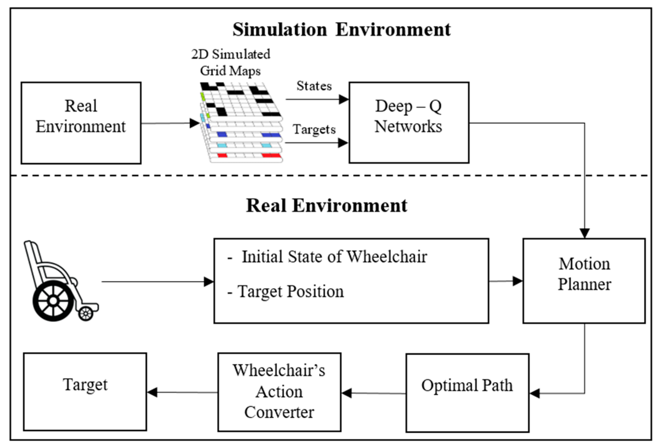
In this research, one system architecture for an optimal path planning is proposed for wheelchair navigation to reach the desired targets. This system architecture includes two stages for the electric wheelchair in an indoor environment as described in Figure 1. In the first stage, the 2D grid maps with cells simulated based on one real indoor environment with different targets will provide information of cell states and targets’ coordinates which are the inputs of DQNs. After being trained, the DQN model will have optimal parameters that can estimate the Q-values of all possible actions for that state. Therefore, the DQNs will have 4 outputs corresponding to 4 actions (Up, Down, Left, Right). Therefore, each 2D grid map is just built for one of the targets in one real indoor environment, so each DQN model is obtained for one MP.
The second stage is that the wheelchair will be controlled to reach the desired target in one real indoor environment. At the start time, the wheelchair will determine its start state itself based on natural landmarks and the desired target position in the real environment is known. When receiving the initial state of the wheelchair on the grid map, the DQN model will estimate the Q-values of 4 outputs corresponding to 4 actions (Up, Down, Left, Right). Therefore, the action with the highest Q-value will be selected. With this action, a new state on the grid map will be updated and then this new state will be the input to the DQN model and it will also select a corresponding action. This process will repeat and end when the state is the target. After navigating the optimal path to be able to reach the desired target, the MP with a sequence of actions (Right, Left, Up, Down) and the WAC will allow the wheelchair to move following this optimal path to reach that desired target.
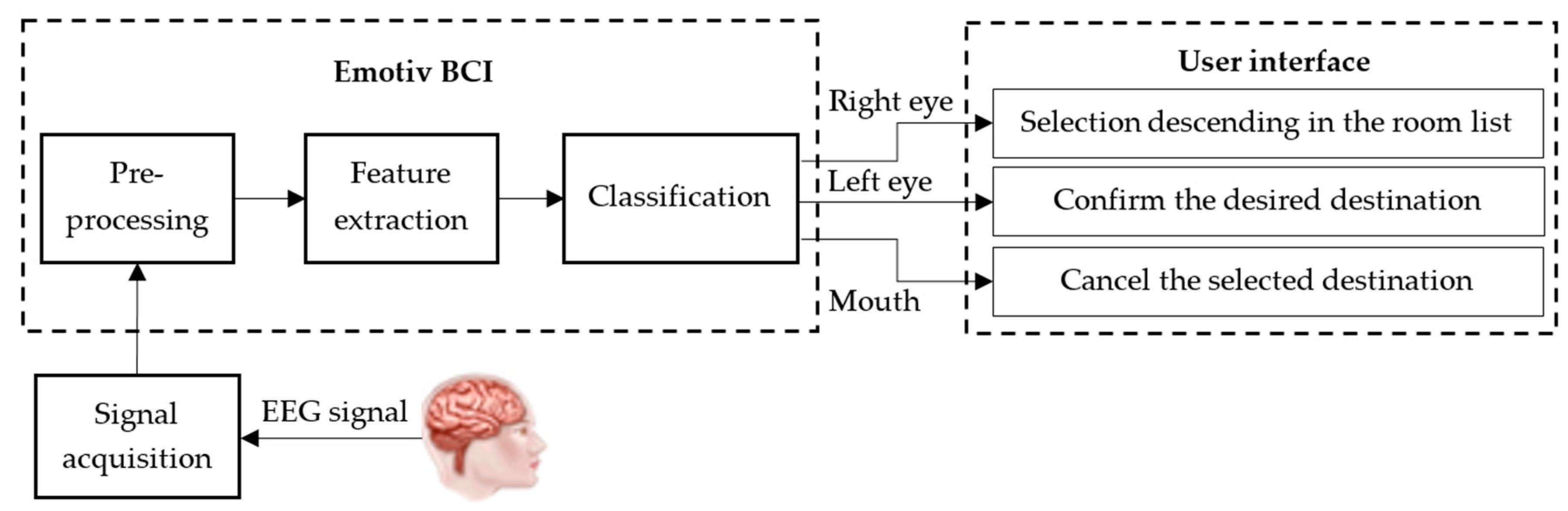
In addition, as shown in Figure 1, the user needs to select a destination on the grid map using EEG signals. In the semi-automatic wheelchair system, the construction and the selection of destinations in a grid map for severely disabled people are a very important task. For people with severe disabilities not able to use normal controls, such as pressing a button, controlling a joystick, or touching a control screen, the EEG signal for controlling the semi-automatic wheelchair is a useful option. Using the EEG signal for directly controlling the semi-automatic wheelchair may cause stress due to concentrating for a long time, so the user can choose the desired destination through a screen interface with commands suitably designed for his/her actual environment [36]. The commands on the interface screen are assigned based on the type of the EEG signal from the user’s face behaviors. Figure 2 describes the process of collecting, processing, and analyzing EEG signals for performing control commands related to the user interface. EEG signals are collected from an Emotiv EPOC system with 14 channels (14 electrodes) [37]. In particular, the EEG signals are collected from the electrodes located in the prefrontal cortex considered to be the most reliable signals. Therefore, the EEG signals are transferred to the signal pre-processing block for filtering and scaling before being sent to the feature extraction block. For the control of the wheelchair, the EEG signals after pre-processing are sent to the classification block for classifying input signals to produce control commands [36,37,38]. It means that the user can use the control commands for selecting one of destinations on the environmental map to reach.
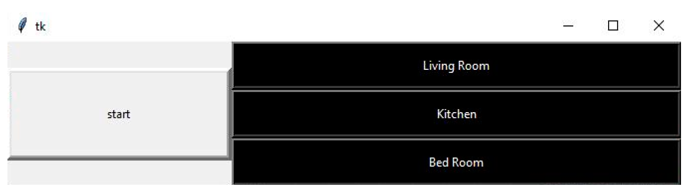
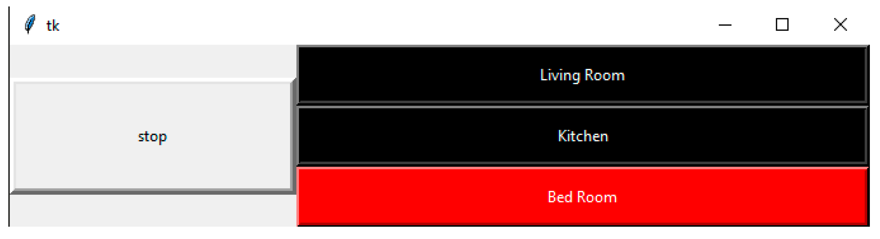
The user interface is always designed to be simple and easy for disabled people, particularly, all commands can be operated using the BCI only as described in Figure 3. On the interface, the user will see a vertical menu with the symbols of destination names. The names in this menu are the pre-defined destinations such as living room, kitchen, and bedroom. To control the commands to reach the destinations, the act of closing the right eye of user is the command for selecting the desired destination. In particular, the user needs to close the right eye for 2 s to be able to move the cursor on the screen to the desired destination and then close the left eye to confirm the desired destination as shown in Figure 4. If the user wants to cancel the selected commands or cancel the selected destination, the user needs to perform the distortion of the mouth to the right. All operations selected for controlling the user interface with the designed destinations were tested on many users and the real results using the designed EEG commands produced the highest accuracy.
2.2. Deep Q-Networks for Optimal Path Planning
In this study, DQNs were applied to find optimal paths as Q-tables based on virtual 2D grid maps through simulation, in which each target uses a virtual grid map and also many optimal paths are found for the wheelchair to reach that target from any start position of the wheelchair. In the DQNs, we could set variables related to the operation of the wheelchair and one real environment, particularly, the wheelchair is called Agent on a virtual 2D grid map (Environment), consisting of obstacles and free spaces. With the positions of start and target, Agent’s task is to reach the target cell. In addition, the Agent interacts with Environment based on Actions (Left, Right, Up, Down). After each Action, Environment returns to Agent and State St = (xt, yt) is the wheelchair position at time t, with the (x, y) grid coordinate, and the reward points (Reward, R) correspond to that State. In addition, Agent has a limited State, St є S, with an m × n pre-defined size of S, and Agent is often placed in the middle of the grid cells for the possibility of moving in all four directions.
In this algorithm, State consists of three types of obstacle So, free space Sf, and target Sg. At each moment t, Agent is the State St and needs to select an Action from a fixed set of possible Actions. Therefore, the decision to select which Action for movement operation is only dependent on the current State, not the Action history, due to being irrelevant. In addition, the result of Action at time at will cause the conversion from the current State St at time t to the new State St+1 at the time (t + 1) and then immediate Reward collected after each Action R(st, at) є [–1, 1] is calculated using the following rule:
Each movement of the wheelchair from one cell to an adjacent cell will lose Rf points and this will prevent it from wandering around and possibly reaching the desired target with the shortest path. In this algorithm, the maximum Reward is Rg points for movement of the wheelchair to hit the target. While the wheelchair tries to enter an obstacle cell, Ro points will be subtracted. It means that this is a serious punishment (penalty), so the wheelchair will learn how to completely avoid the punishment and so the effort to move to an obstacle cell is invalid and cannot be performed. The same rule for an attempt to move outside the map boundary with a punishment of Rb points applies. The case is that the wheelchair will lose Rp points for any movement to the cell that has been passed. Moreover, to avoid infinite loops during the training process using the DQNs, the total Reward is bigger than the negative threshold (thr × m × n) and then the wheelchair can move normally. Inversely, the movement of the wheelchair can be lost and many errors can be made, so the training needs to be carried out again until the total Reward is enough.
In this DQN, the main learning model is a Feedforward Neural Network (FWNN) with backpropagation training algorithm, in which the environmental States are the input of the network and bring Rewards back for each Action vector. The goal of Agent is to move following the map by a Policy to obtain a maximum Reward from the Environment. Therefore, Policy π at State st produces an Action at so that the total Reward Q Agent receives is the largest and is calculated by the following equation:
in which Q(st, ai) are Actions, ai (i = 0, 1,…, (n−1)), n denotes the number of Actions and satisfies the following equation of Bellman [35], st+1 is the next State, γ denotes the discount coefficient which makes sure that Agent is far from the target and it is smaller than the Q-value.
For approximating Q(st, at), the FWNN has the input as a State and its output is the vector Q, in which the Q-value corresponds to n Actions. In addition, Qi approximates the value of Q(st, ati) for each Action ati. When the network is fully and accurately trained, it will be used in the optimal path planning model for selecting Policy π as follows:
in which the value j is determined based on the maximum Q.
The purpose of the neural network model is to learn how to exactly estimate the Q-value for Actions, so the objective/goal function applied here is to calculate the error Loss between the actual and predicted values Q and it is described by the following equation:
In addition, the FWNN model has the input of the current State and the outputs of the values Q. However, if the input of the FWNN is continually pushed into each State, it is very easily overfitted because the States are often the same and linear. For eliminating the overfitting problem in the FWNN model, a technique, called experience replay [23], is applied. In particular, instead of each State, the network is updated once, and the State is saved into memory and then sampled as small batches connected to the input of the FWNN for training. Therefore, it may provide diversification of the FWNN input and also avoid the overfitting problem. In this case, the training model will forget old samples not good enough for the training process and then they will be deleted from memory.
The FWNN model used in the training system has two hidden layers with the number of nodes equal to that of cells in the virtual 2D grid map built in the indoor environment. In addition, the size of the input layer is similar to the hidden one due to States of the virtual map used as the input. The output layer has the number of neurons equal to Actions (four Actions used in this paper) due to predicting the Q-value to estimate each Action. Finally, the FWNN model will choose the largest Q-value to perform an Action for the next State. In this research, the Parametric Rectified Linear Unit (PReLU) activation function, the optimization method of RMSProp, and the loss function of Mean Squared Error (MSE) are applied in the model for optimal path planning.
in which yi is any input on the ith layer and ai is the negative slope which is a learnable parameter.
2.3. Wheelchair Navigation in Real Environment
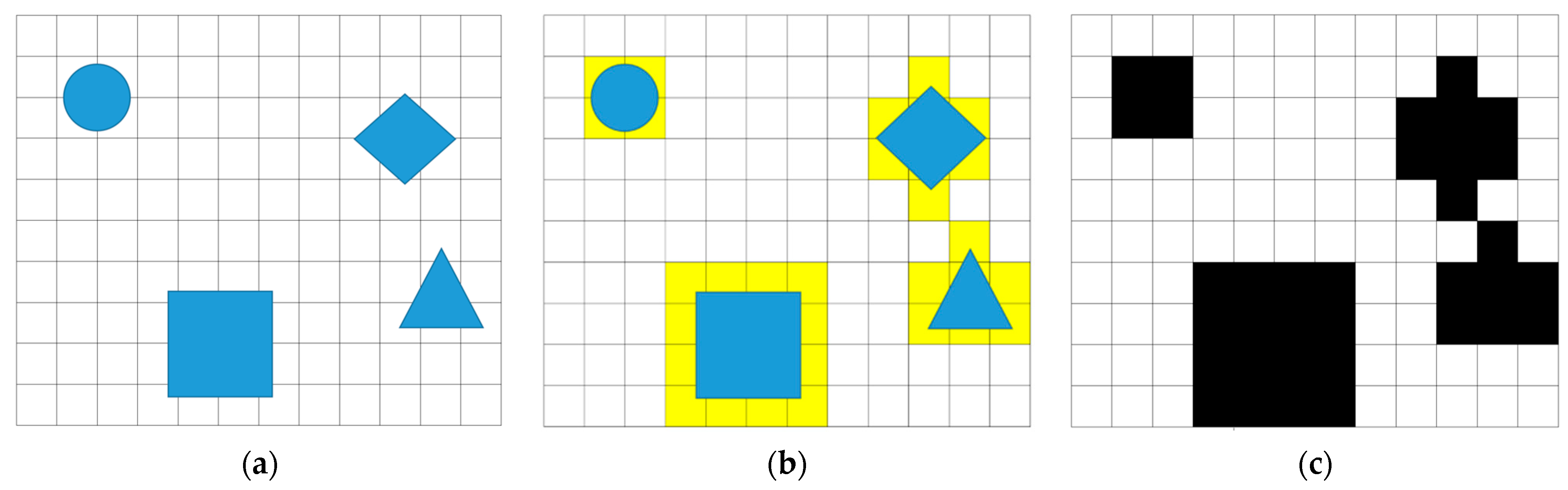
In the optimal path planning, a simulated 2D grid map plays one very important role due to showing optimal paths for navigating the electric wheelchair to targets. In particular, one 2D grid map is simulated based on a lot of information related to one real environment. It means that the wheelchair, when moving in one real environment, may use parameters and State values for wheelchair navigation. Therefore, the simulated 2D grid map is divided into a lot of cells, including free spaces and occupancies. Each cell is calculated to be an actual area in the real environment with free spaces and obstacles and it can be one free space or one occupancy (obstacle). Therefore, we assume that the wheelchair can be driven through these free space areas to reach the desired target.
Figure 5 describes the 2D grid maps with occupancies and cells, including m × n cells in the indoor environment, in which the wheelchair can move through to reach targets. In particular, the real environment with objects (blue) is measured and divided into cells with the size of the wheelchair for creating the map as shown in Figure 5a. Therefore, the map with the divided cells is converted into a 2D grid map with calculation for filling cells related to obstacles (yellow). Therefore, the 2D grid map in Figure 5b is simulated to create the virtual 2D grid map as described in Figure 5c. The cells in the virtual 2D grid map are assigned 1 s to represent the occupied workspace (obstacles) and 0 s for the free workspace. Therefore, this virtual 2D grid map is considered as a binary map with black and white cells and the original coordinate of the virtual map is in the top left corner with the first location (0,0). It is obvious that this virtual map lets us know all cell locations which are used to find optimal paths using the algorithm of DQNs.
In this model, the wheelchair is located on a map through landmarks including the location and direction of the wheelchair on the map. The update of the position of the wheelchair is carried out when starting the movement for the first time. In this method, only the wheelchair location is connected to the input of the MP block for determining the optimal path and then it shows specific Actions with that State of the wheelchair.
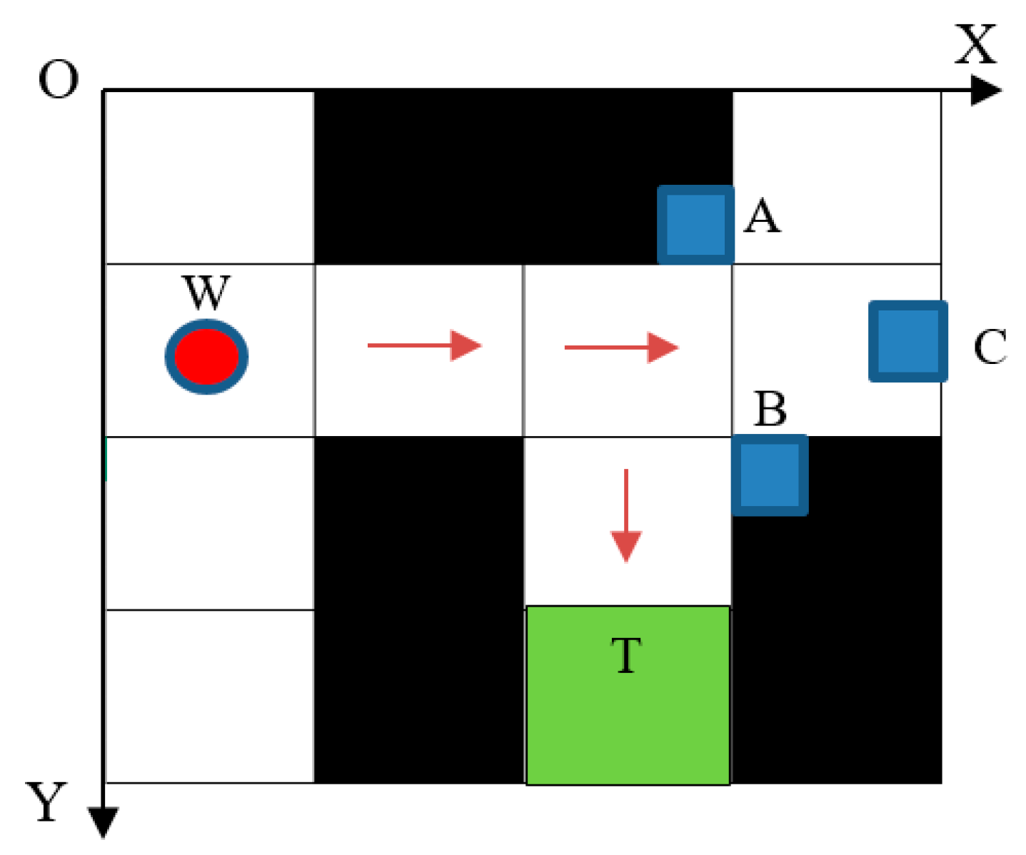
One of the most important parts in the wheelchair control system is the wheelchair location in a real indoor environment for navigation. In a real indoor environment, natural landmarks will be automatically collected for creating one database for locating the motion wheelchair. In particular, the Features from Accelerated Segment Test (FAST) method is used to extract features of images captured from the camera system. Therefore, objects in the image that have the largest density of feature points are chosen to be natural landmarks and then the Speeded-Up Robust Features (SURF) algorithm is applied to identify these landmarks [39]. In this research, when the wheelchair is in the real environment as described in Figure 6, its initial location is determined based on three landmarks captured from a camera system installed on the wheelchair. Assume that the wheelchair moves in the flat space OXY with the unknown coordinates W(x, y) and landmarks related to the coordinates in the real indoor environment. Therefore, obstacles selected as landmarks have distinctive characteristics which are different from other landmarks with their coordinates A(xA, yA), B(xB, yB), and C(xC, yC) [40]. The wheelchair position can be determined if the coordinates of the landmarks and the corresponding distances from the wheelchair to the landmarks are known. Based on the wheelchair location determined as above, the wheelchair position on the real grid map with the square cell size (a × a) is .
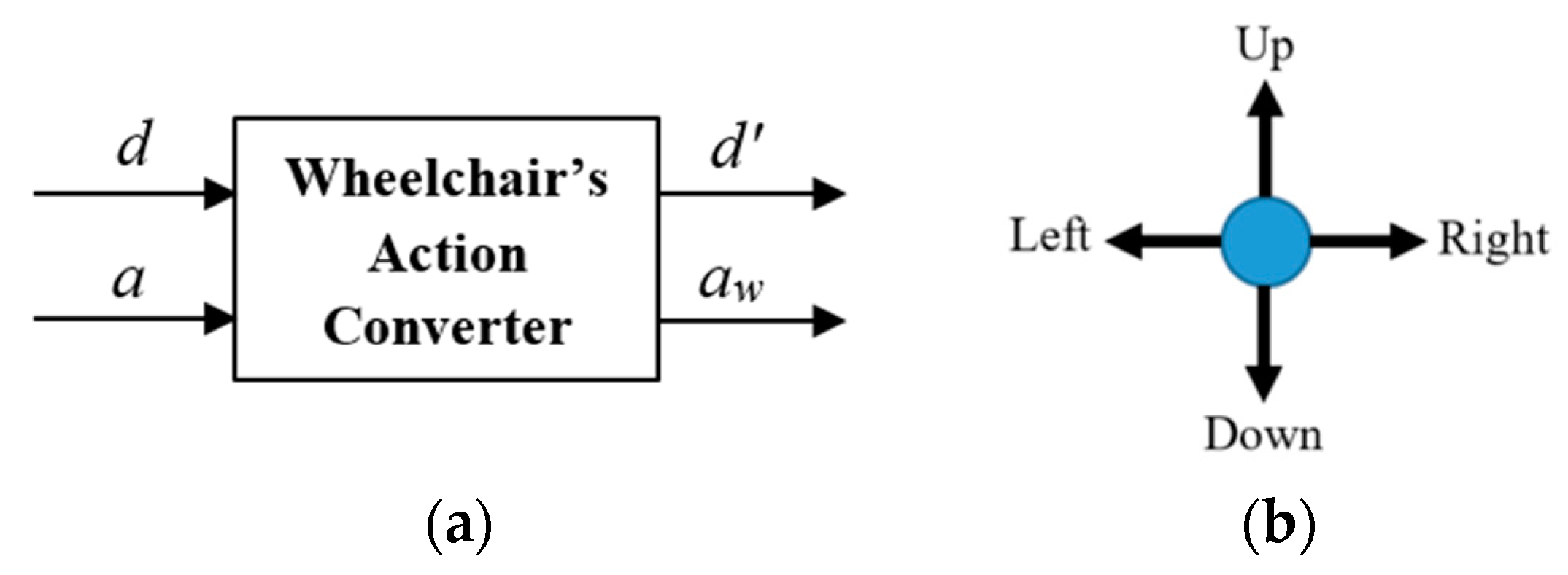
The starting point SW(1,0) ϵ Sf and the target Ti(3,2) ϵ T are obtained based on the pre-trained map with this target, in which Sf is a set of free cells and T is a set of known targets. Therefore, the MP gives one optimal path which is a set of Actions including Right, Right, Down, Down as shown in Figure 6. It means that the wheelchair impossibly moves based on these Actions due to the wheelchair model in this research not being an omnidirectional control model. In Figure 7a, the two-input converting block is Action a, determined from the MP output, and the initial direction d of the wheelchair includes the four directions (Up, Down, Left, Right) as described in Figure 7b. Thus, the output of the converting block aw is an Action that is suitable with the wheelchair orientation/direction in the real environment.
The training process for finding the optimal path will produce a series of Actions with different States, in which these Actions will produce many optimal paths dependent on the initial position of the wheelchair. Therefore, after each Action a, the wheelchair direction d will change into a new direction d′. For the movement of the wheelchair, we propose a novel algorithm based on the WAC as described in Figure 7. In particular, the wheelchair Actions aw and the new direction d′ = a during its movement in real environment need to be determined and this algorithm is expressed as follows:
in which a and d are the parameters which are determined based on Action and direction in MP. In Equations (8a)–(8d), the wheelchair Actions aw are defined as follows:
- aw = Forward: The wheelchair will go straight;
- aw = Backward: The wheelchair will go back;
- aw = Left-Forward: The wheelchair will rotate left and then go straight;
- aw = Right-Forward: The wheelchair will rotate right and then go straight;
- aw = Stop if a = no Action: The wheelchair will stop.
3. Results and Discussion
3.1. Simulation of Path Training for the Wheelchair Based on 2D Grid Map
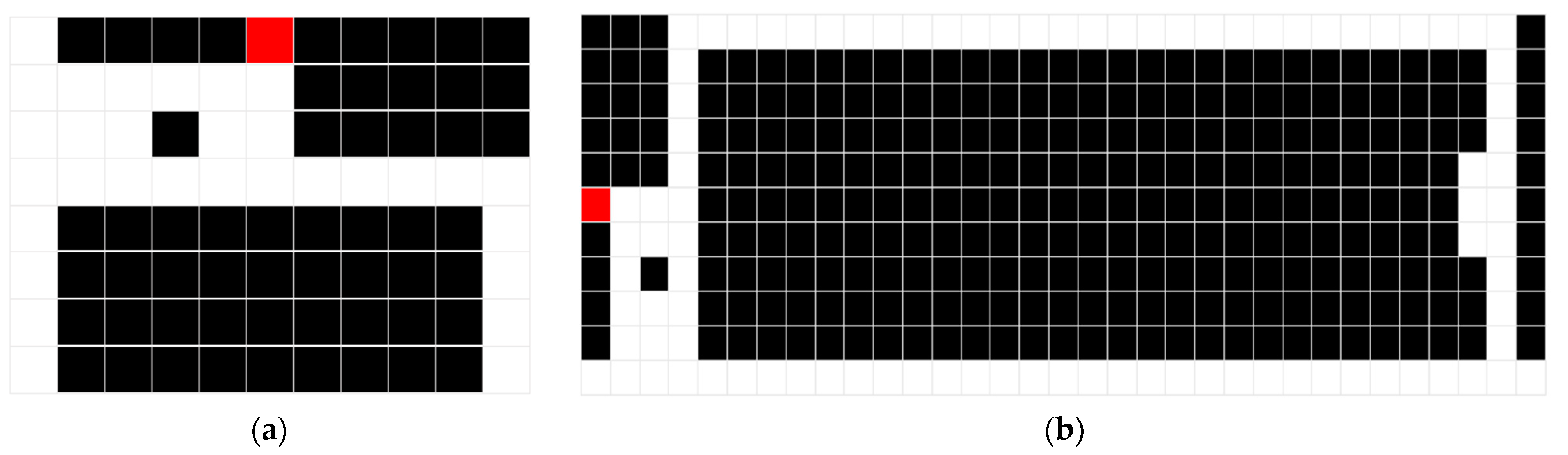
We constructed two grid maps depicting the indoor environment as shown in Figure 8, where the white cells are the spaces, the black cells are the obstacles, and the red cells are the targets. During training and testing the proposed structure, the PC configuration with the Windows operating system was Intel (R) Core (TM) i5-6300U, 2.4 GHz, 16 GB RAM. During each training, the starting position is randomly selected in the map and guaranteed not to overlap with the obstacle cell. Table 1 describes the parameters which are trained in the case as described in Figure 8.
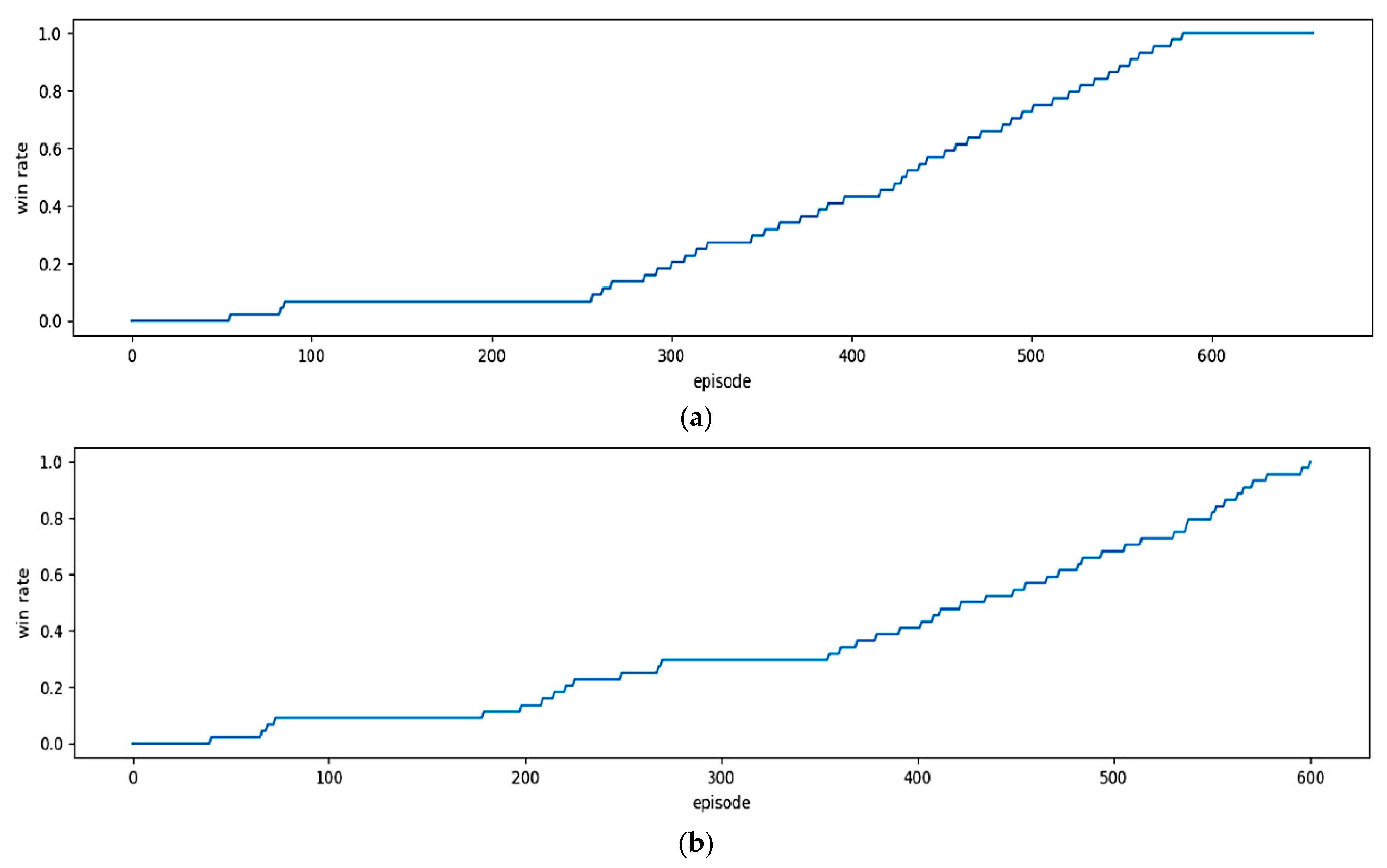
To evaluate the effectiveness of the DQN method, we performed the experiment with different steps and different environments, and the stable results of the DQN method are shown in Figure 9 and Figure 10 for each environment. In particular, we worked out the experiment of the proposed model using DQNs with two activations of PReLU and ReLU for comparing the performance between them, where the horizontal axis is the number of episodes and the vertical axis is the Win rate. The Win rate is calculated based on the number of Wins per the total number of selected positions to start a game in an episode. From Figure 9, we can see that the Win rate can increase or decrease or stay the same after each episode.
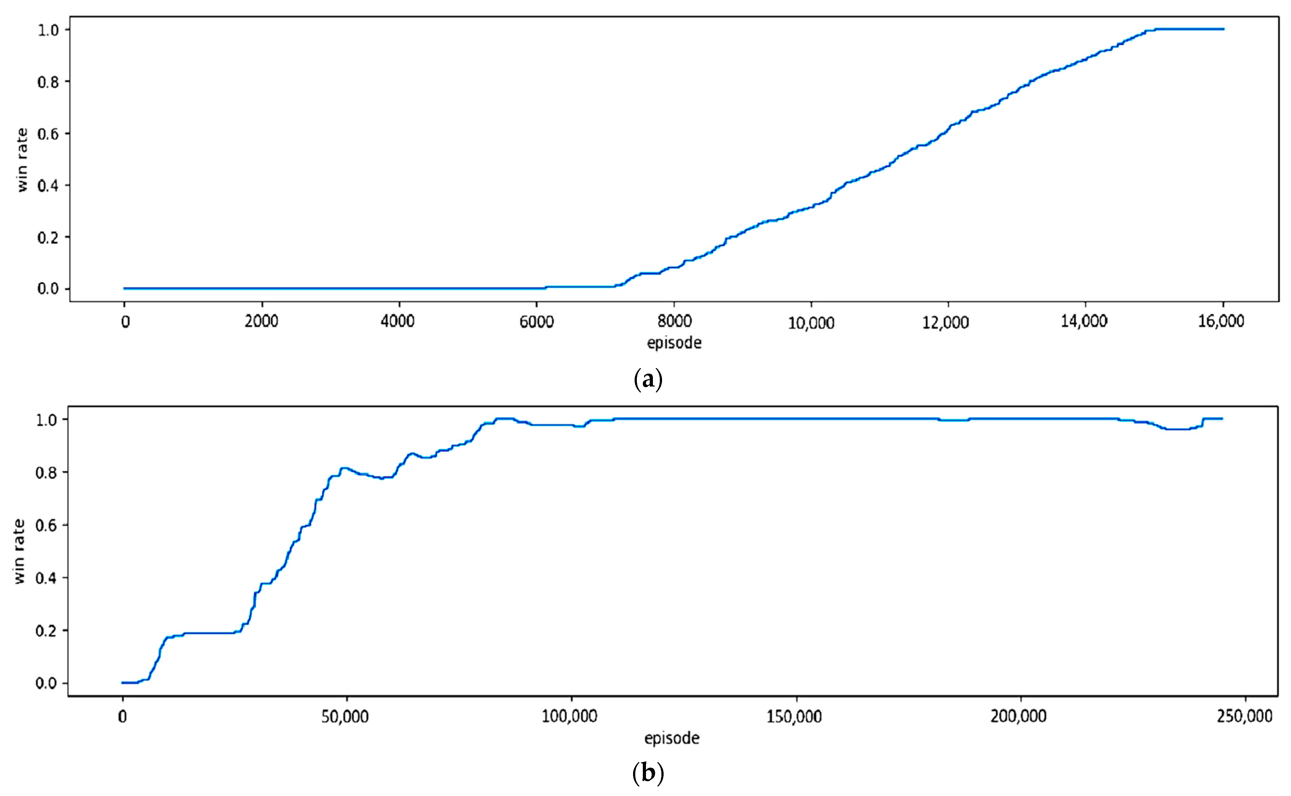
According to the results in Figure 9 with a small environment, the two models of DQNs-PReLU and DQNs-PReLU have the same Win rate growth path and also reach the maximum Win rate threshold of 1 after about 600 episodes. Figure 10 shows the Win rate growth of the large environment with the two selected models. With the results of the model of DQNs-PReLU in Figure 10a, when the episode is over 7000, the Win rate starts sharply increasing and then reaches the maximum threshold at episode 15,000. Therefore, the Win rate reaches saturation and this shows that the model meets the training requirements and then ends. In contrast, according to the results shown in Figure 10b using the model of DQNs-ReLU, the Win rate starts sharply increasing when the episode is over 25,000 and reaches the maximum threshold when the episode is 240,000. After that, the Win rate reaches saturation and this means that the model meets the requirements of training and then ends. Thus, it can be seen that in a large environment, the model of DQNs-PReLU more quickly reaches the maximum score than DQNs-ReLU.
In addition, the obtained results are comparable in terms of training time and the number of episodes of the DQN model with the two types of activations as shown in Table 2. In particular, in the small environment with 8 × 11, the difference in training time is not too large, 36.3 s compared to 42.3 s for two ReLU and PReLU activations, respectively. With the episode number of the two models of DQNs-ReLU and DQNs-PReLU used for training, this environment is not much different, with episode numbers of 601 and 607, respectively. However, with the larger environment of 11 × 33, there is a big difference in training time and the number of episodes between the two models. In particular, the training time of the DQNs-ReLU model is nearly 4 times larger than that of the DQNs-PReLU model. In addition, the average number of episodes per training time using the DQNs-ReLU model is 15 times that of the DQNs-PReLU. This means that the DQNs-PReLU model gives better performance than DQNs-ReLU using this environment.
Table 3 describes the comparison of episode and time using the DQN model with two activations and previous models in training the two environments (small and large). In all experiments of randomly trained models, we performed training of each case 10 times to take the average training time and the average number of episodes. It is obvious that the Traditional Q-Learning model shows a table to record the value of each pair (State, Action), in which the State with the highest value indicates the most desirable Action. Therefore, these values are constantly refined during training and this is a quick way to learn a Policy. The second model, called the SARSA model, uses a setup similar to the previous model, but takes fewer risks during learning. During the training process, depending on the small or large environment, the training time and the number of episodes will be different.
In particular, with a small environment, the training time and the number of episodes are less than those with a large environment as shown in Table 2 and Table 3. Furthermore, in Table 3, the models have a small number of episodes and a lot of time because Traditional Q-Learning works based on finding the maximum reward for each step and the larger the number of States, the larger the Q-table, so the calculation will take a lot of time. Meanwhile, in Table 2, the DQN has a lot of episodes but it takes less computation time because the DQN chooses some random and risky decisions to quickly obtain a high reward and it will accept to lose a certain amount of episodes.
With the statistical results in Table 2 and Table 3, although the number of episodes in the training process is much larger than that of the Q-table-based models in Table 3, the DQNs-PReLU model in Table 2 takes a longer training time in two training cases for both small and large environments. In particular, for the small environment, the model of DQNs-PReLU has about 10 times more episodes than the models of Traditional Q-Learning and SARSA, but its training time is almost 5 times less than that of the Traditional Q-Learning and SARSA. In addition, with a large environment, DQNs-PReLU has a large number of about 16,015 episodes, nearly 60 times more than that using the Traditional Q-Learning, and nearly 70 times more than that using the SARSA model. However, the training time is significantly reduced with about 35.24 min compared to that of two models in Table 3, 1.45 h and 57.23 min, respectively. As an extra feature after learning, it saves the model to disk so this can be loaded later for the next game. Therefore, a neural network needs to be used in a real-world situation where training is separated from actual use.
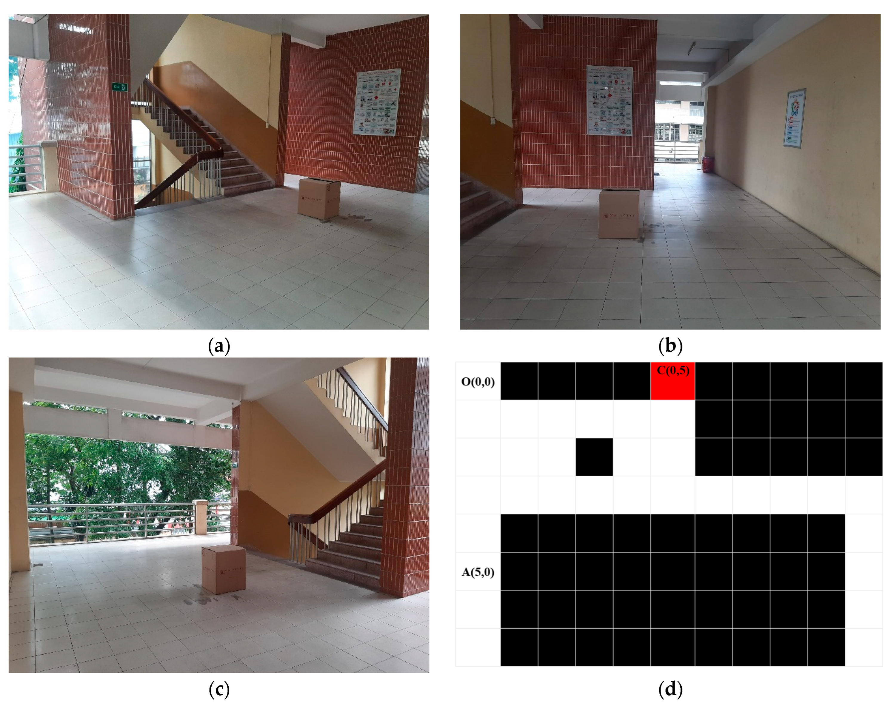
3.2. Wheelchair Movement to Reach Map-Based Desired Target
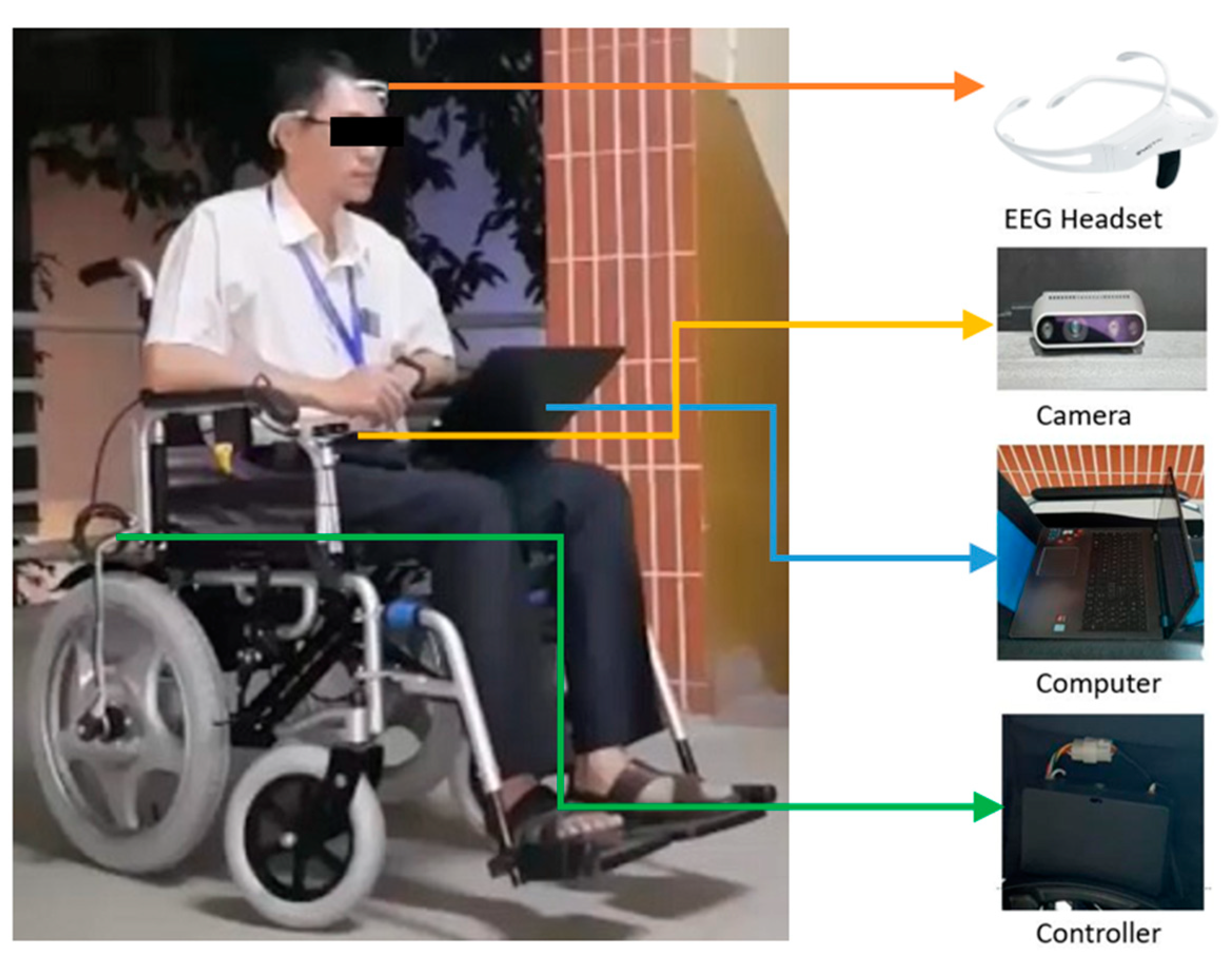
The experiment was performed in an environment of 126.72 m2 which was divided into square grids of one map with a size of 8 × 11, in which each square has a size of 1.2 m × 1.2 m as shown in Figure 11. The wheelchair was installed to be able to move at the speed of 3 km/h for matching the processing speed of the system. An electrical wheelchair was installed with an RGB-D camera system and other equipment as shown in Figure 12. Information about the surrounding environment obtained from the camera system was processed by a computer and then transferred to the motor system of the wheelchair for motion control. In addition, in this research, we performed two experiments, including a self-control user and an automatic control user. In the self-control user model, the user can self-control commands such as going forward, backward, and turning right and left during the wheelchair movement. Meanwhile, the automatic control user mode means that the user can choose one of the targets by using EEG signals which are assigned to the targets to reach [36] and our proposed algorithm in the wheelchair control system is applied so that the wheelchair can automatically reach the chosen target.
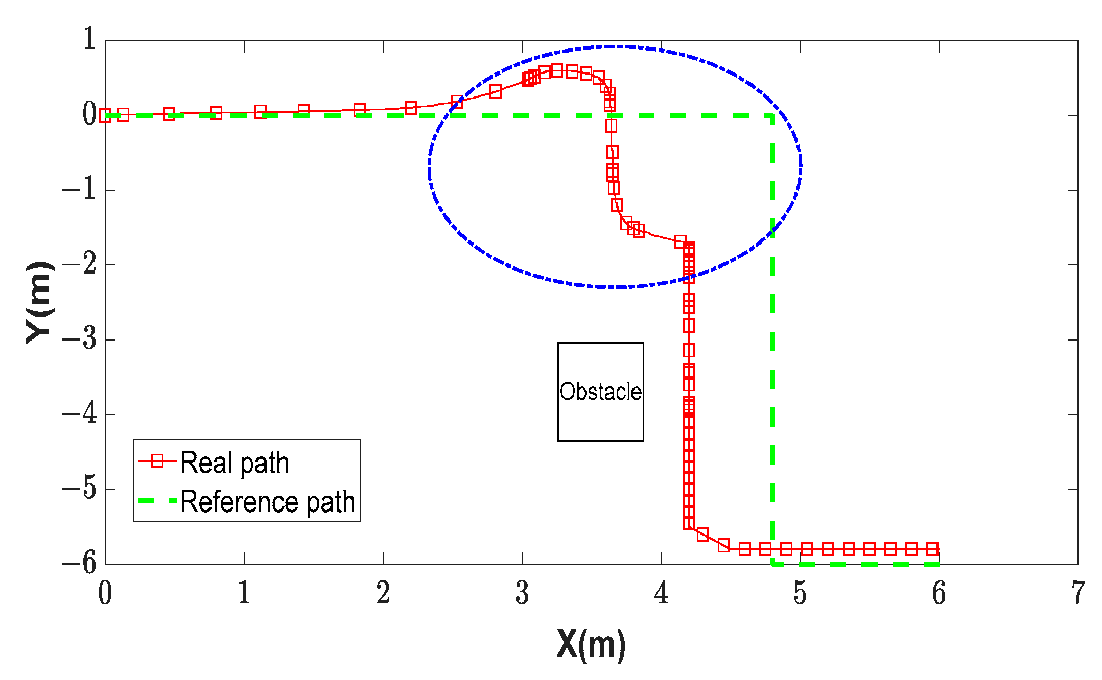
Figure 13 shows the green real path of the wheelchair, which was controlled by the user during reaching the target. In particular, the discontinuous green path is the desired path in the real environment that the wheelchair needs to follow to reach the target, while the red path of the wheelchair is the path controlled by self-control mode using EEG signals [38] to go straight, turn left and right during reaching the destination. With the experiment using the self-control, the wheelchair moved according to the red path and then turned to the undesired direction shown by the red path and blue dash-dot ellipse. It means that in this case, the wheelchair could very easily have an obstacle collision. In addition, with the mode of the self-control, the movement of the wheelchair is unstable and discontinuous as shown in Figure 13. In particular, the wheelchair went straight, then stopped, turned right, and then was continuously interrupted during the movement time. It is obvious that the user was trying hard to control it to turn right or left and go straight.
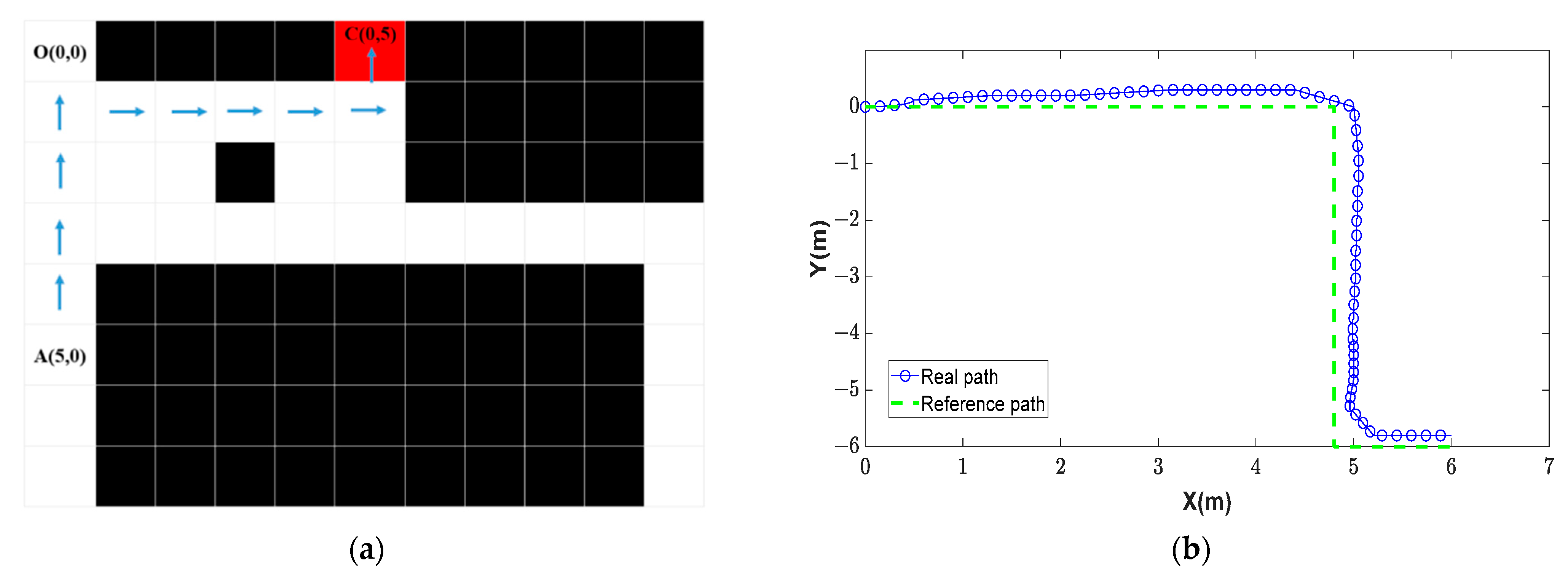
For improving the wheelchair control using the self-control mode, we used the proposed model with the semi-automatic control. With this mode, the user just needs to choose one typical target by using EEG commands and then the wheelchair will automatically move to reach the desired target with high stability and smoothness. In particular, using the environmental map in Figure 11a–c, the actual paths of the wheelchair after moving to reach the target were as shown in Figure 14b. Therefore, the moving process was re-calculated and the path positions of the wheelchair with the axes of X and Y were re-drawn for the purpose of the comparison with the simulation paths (blue arrows) as shown in Figure 14a. The starting point of the wheelchair is random and the wheelchair automatically determines its position on the map by identifying landmarks in the environment. In particular, in this case, the wheelchair determined it position on the grid map at the coordinate A(5,0) and the direction of the wheelchair d is Up. In the semi-automatic wheelchair, people with disabilities can control the wheelchair using EEG signals to select one of the commands on the interface screen with one sign corresponding to the target C(0,5). With the starting point A(5,0) and the target point C(0.5) selected, the RL model will produce a sequence of control commands for the path and then these commands are converted to control commands in the real environment for the wheelchair using Equations (8a)–(8d) as shown in Table 4.
In addition, in this experiment, the actual path of the wheelchair with the proposed method of DQNs (blue path) is compared with the standard path (green dashed path), as shown in Figure 14b, for evaluating the wheelchair movement path and the simulated path. The results showed that the wheelchair could move to reach the desired target with the average error of ±0.2 m in the X axis and ±0.2 m in the Y axis.
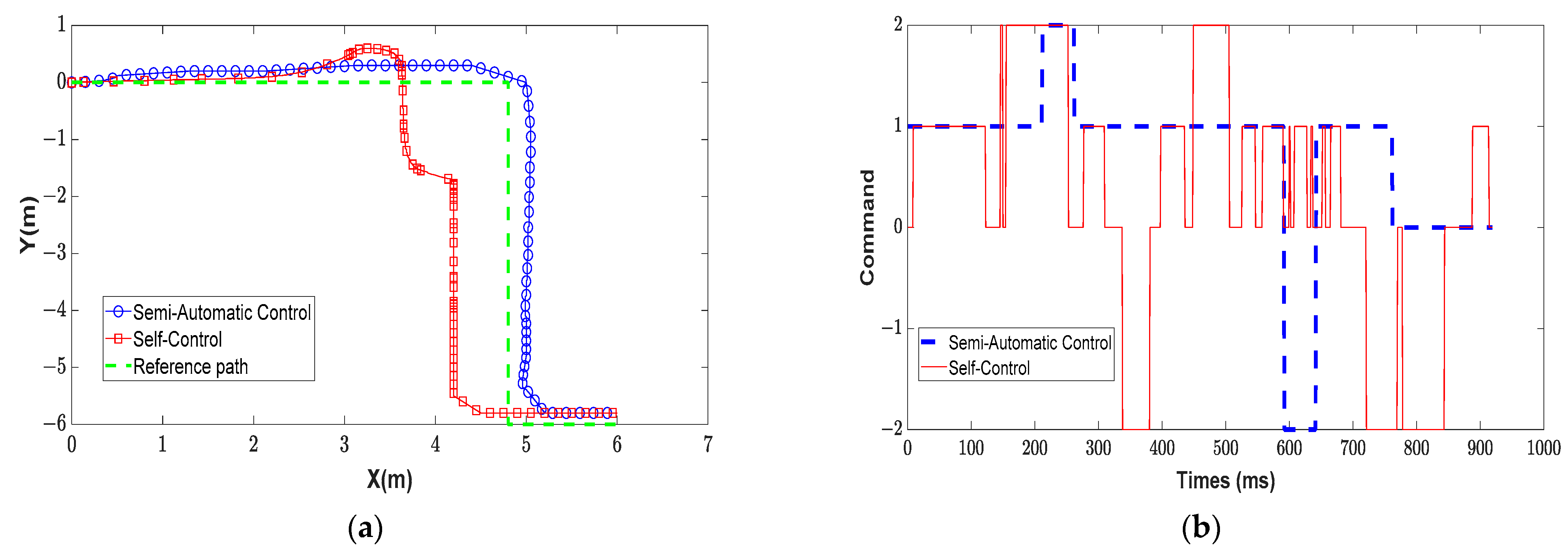
The purpose of these experiments is to compare the results of the semi-automatic control using the RL method with the self-control by the user using the EEG signals. In particular, Figure 15a shows three graphs which represent the wheelchair movements, in which the blue path is that of the proposed mode and the red path is that of the self-control mode. From Figure 15a, it can be seen that the wheelchair’s path when controlled by the semi-automatic control method is closer to the reference path than when using the self-control method. In addition, the wheelchair path using the semi-automatic control is smoother and more continuous than the path using the self-control. To clarify the two control methods, we recorded the wheelchair control commands during the movement to reach the destination.
In Figure 15b, the control commands are shown on the vertical axis with the values of −2, 0, 1, 2 corresponding to the commands to turn left, stop, go straight, and turn right. Therefore, it could be seen that the wheelchair moved with high stability in the case of the semi-automatic control with different movement environments compared to the mode of the self-control user. In addition, the result showed that the automatic control user mode spends less time on wheelchair movement with the average of about 80 s compared to that of the self-control user with the average time of about 95 s.
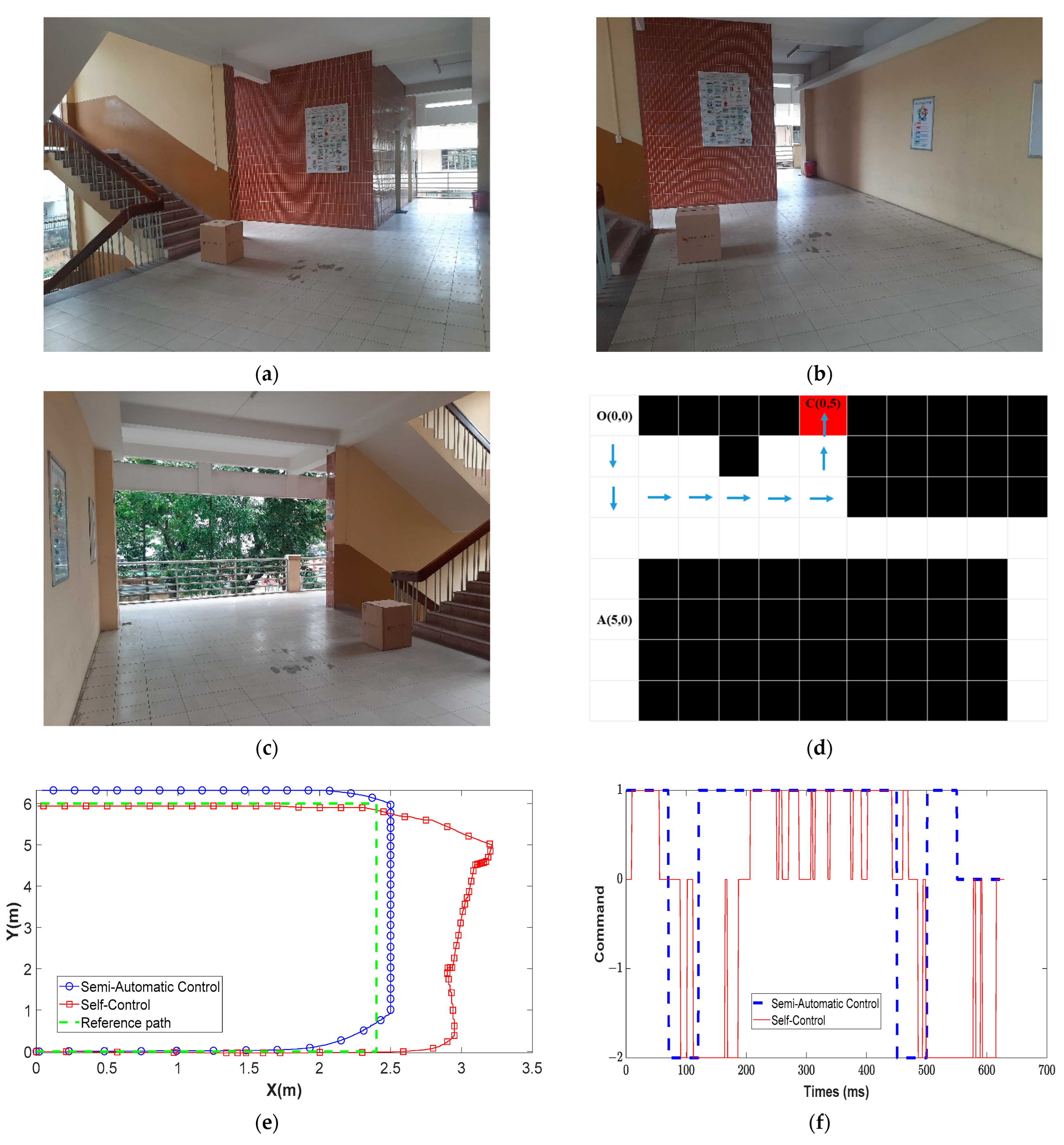
In another case, Figure 16d shows the simulation paths (blue arrows) of the wheelchair based on the environmental map in Figure 16a–c when the wheelchair moves from O(0,0) to C(0,5). From Figure 16e, it can be seen that the wheelchair’s path controlled by the semi-automatic control method is shorter and smoother compared to the self-control method. Further, the semi-automatic control method has an average error of 0.1 m in the X axis and 0.3 m in the Y axis compared with ±0.5 m in the X axis and ±0.5 m in the Y axis of the self-control method. With Figure 16f, it can be seen that the wheelchair moved with high stability in the case of the semi-automatic control with different movement environments compared to the mode of the self-control user.
4. Conclusions
The paper presents a semi-control method of an electric wheelchair combined with an RGB-D camera system, a graphical user interface, and real environmental maps with natural landmarks, in which optimal path planning for the wheelchair navigation was determined. In particular, 2D grid maps were used for training to create the shortest paths to the targets, in which the virtual-real RL method using DQNs carried out the training process effectively. After training, disabled people may select the desired target on the interface-user map using EEG signals to reach it. Therefore, the semi-control wheelchair located itself based on natural landmarks during movement following the optimal path from the motion planner in the real indoor environment. With the proposed method for the optimal path based on DQNs, the semi-control wheelchair could operate well to reach the desired target with small errors compared to the simulation trajectory, as well as to the trajectory of the self-control user using an EEG system. It is obvious that, with our proposed optimal path trajectory and the semi-automatic control method, the semi-control wheelchair movement is more stable, safe, and takes less time for moving. As a result of the proposed method, this wheelchair control system can be developed to apply to more complex environments with obstacles in the future.
Author Contributions
Conceptualization, methodology, simulation, and writing original draft, B.-V.N.; methodology, supervision, validation and writing—review and editing, T.-H.N. All authors have read and agreed to the published version of the manuscript.
Funding
This research received no external funding.
Institutional Review Board Statement
Not applicable.
Informed Consent Statement
Not applicable.
Data Availability Statement
Not applicable.
Acknowledgments
We would like to thank Ho Chi Minh City University of Technology and Education, Vietnam.
Conflicts of Interest
The authors declare no conflict of interest.
References
- Kim, E.Y. Wheelchair Navigation System for Disabled and Elderly People. Sensor 2016, 16, 1806. [Google Scholar] [CrossRef] [PubMed]
- Xu, X.; Zhang, Y.; Luo, Y.; Chen, D. Robust Bio-Signal Based Control of an Intelligent Wheelchair. Sensors 2013, 2, 187–197. [Google Scholar] [CrossRef]
- Xi, L.; Shino, M. Shared Control of an Electric Wheelchair Considering Physical Functions and Driving Motivation. Int. J. Environ. Res. Public Health 2020, 17, 5502. [Google Scholar] [CrossRef]
- Kim, J.; Park, H.; Bruce, J.; Sutton, E.; Rowles, D.; Pucci, D.; Holbrook, J.; Minocha, J.; Nardone, B.; West, D.; et al. The tongue enables computer and wheelchair control for people with spinal cord injury. Sci. Trans. Med. 2013, 5, 1–22. [Google Scholar] [CrossRef] [PubMed]
- Dahmani, M.; Chowdhury, M.; Khandakar, A.; Rahman, T.; Al-Jayyousi, K.; Hefny, A.; Kiranyaz, S. An Intelligent and Low-Cost Eye-Tracking System for Motorized Wheelchair Control. Sensors 2020, 20, 3936. [Google Scholar] [CrossRef] [PubMed]
- Shahin, M.K.; Tharwat, A.; Gaber, T.; Hassanien, A.E. A Wheelchair Control System Using Human-Machine Interaction: Single-Modal and Multimodal Approaches. J. Intell. Syst. 2019, 28, 115–132. [Google Scholar] [CrossRef]
- Barriuso, A.L.; Pérez-Marcos, J.; Jiménez-Bravo, D.M.; Villarrubia González, G.; de Paz, J.F. Agent-Based Intelligent Interface for Wheelchair Movement Control. Sensors 2018, 18, 1511. [Google Scholar] [CrossRef]
- Belkacem, A.N.; Jamil, N.; Palmer, J.A.; Ouhbi, S.; Chen, C. Brain Computer Interfaces for Improving the Quality of Life of Older Adults and Elderly Patients. Front. Neurosci. 2020, 14, 692. [Google Scholar] [CrossRef]
- Hramov, A.E.; Maksimenko, V.A.; Pisarchik, A.N. Physical principles of brain–computer interfaces and their applications for rehabilitation, robotics and control of human brain states. Phys. Rep. 2021, 918, 1–133. [Google Scholar] [CrossRef]
- Wang, H.; Yan, F.; Xu, T.; Yin, H.; Chen, P.; Yue, H.; Bezerianos, A. Brain-Controlled Wheelchair Review: From Wet Electrode to Dry Electrode, From Single Modal to Hybrid Modal, From Synchronous to Asynchronous. IEEE Access 2021, 9, 55920–55938. [Google Scholar] [CrossRef]
- Fuentes-Pacheco, J.; Ruiz-Ascencio, J.; Rendón-Mancha, J.M. Visual simultaneous localization and mapping: A survey. Artif. Intell. Rev. 2015, 43, 55–81. [Google Scholar] [CrossRef]
- Cras, J.L.; Paxman, J. A modular hybrid SLAM for the 3D mapping of large scale environments. In Proceedings of the 12th International Conference on Control Automation Robotics & Vision (ICARCV), Guangzhou, China, 5–7 December 2012; pp. 1036–1041. [Google Scholar]
- Han, S.B.; Kim, J.H.; Myung, H. Landmark-Based Particle Localization Algorithm for Mobile Robots with a Fish-Eye Vision System. IEEE/ASME Trans. Mechatron. 2013, 18, 1745–1756. [Google Scholar] [CrossRef]
- Alcantarilla, P.F.; Oh, S.M.; Mariottini, G.L.; Bergasa, L.M.; Dellaert, F. Learning visibility of landmarks for vision-based localization. In Proceedings of the IEEE International Conference on Robotics and Automation (ICRA), Anchorage, AK, USA, 3–7 May 2010; pp. 4881–4888. [Google Scholar]
- Wang, H.; Ishimatsu, T. Vision-Based Navigation for an Electric Wheelchair Using Ceiling Light Landmark. J. Intell. Robot. Syst. 2004, 41, 283–314. [Google Scholar] [CrossRef]
- Hu, G.; Huang, S.; Zhao, L.; Alempijevic, A.; Dissanayake, G. A robust RGB-D SLAM algorithm. In Proceedings of the IEEE/RSJ International Conference on Intelligent Robots and Systems, Vilamoura-Algarve, Portugal, 7–12 October 2012; pp. 1714–1719. [Google Scholar]
- Basu, A.; Ghosh, S.K.; Sarkar, S. Autonomous navigation and 2D mapping using SONAR. In Proceedings of the 5th International Conference on Wireless Networks and Embedded Systems (WECON), Rajpura, India, 14–16 October 2016; pp. 1–5. [Google Scholar]
- Liu, X.; Guo, B.; Meng, C. A method of simultaneous location and mapping based on RGB-D cameras. In Proceedings of the 14th International Conference on Control, Automation, Robotics and Vision (ICARCV), Phuket, Thailand, 13–15 November 2016; pp. 1–5. [Google Scholar]
- Zhong, X.; Zhou, Y.; Liu, H. Design and recognition of artificial landmarks for reliable indoor self-localization of mobile robots. Int. J. Adv. Robot. Syst. 2017, 14, 1–13. [Google Scholar] [CrossRef]
- Yu, T.; Shen, Y. Asymptotic Performance Analysis for Landmark Learning in Indoor Localization. IEEE Commun. Lett. 2018, 22, 740–743. [Google Scholar] [CrossRef]
- Viet, N.B.; Hai, N.T.; Hung, N.V. Tracking landmarks for control of an electric wheelchair using a stereoscopic camera system. In Proceedings of the International Conference on Advanced Technologies for Communications (ATC 2013), Ho Chi Minh City, Vietnam, 16–18 October 2013; pp. 339–344. [Google Scholar]
- Montero, A.S.; Sekkati, H.; Lang, J.; Laganière, R.; James, J. Framework for Natural Landmark-based Robot Localization. In Proceedings of the 9th Conference on Computer and Robot Vision, Toronto, ON, Canada, 28–30 May 2012; pp. 131–138. [Google Scholar]
- Mnih, V.; Kavukcuoglu, K.; Silver, D.; Rusu, A.A.; Veness, J.; Bellemare, M.G.; Graves, A.; Riedmiller, M.; Fidjeland, A.K.; Ostrovski, G.; et al. Human-level control through deep reinforcement learning. Nature 2015, 518, 529–533. [Google Scholar] [CrossRef]
- Lillicrap, T.P.; Hunt, J.J.; Pritzel, A.; Heess, N.; Erez, T.; Tassa, Y.; Silver, D.; Wierstra, D. Continuous control with deep reinforcement learning. In Proceedings of the ICLR 2016, San Juan, Puerto Rico, 2–4 May 2016. [Google Scholar]
- Gu, S.; Lillicrap, T.; Sutskever, I.; Levine, S. Continuous deep Q-Learning with model-based acceleration. In Proceedings of the 33rd International Conference on Machine Learning, New York, NY, USA, 19–24 June 2016; pp. 2829–2838. [Google Scholar]
- Khan, M.U. Mobile Robot Navigation Using Reinforcement Learning in Unknown Environments. Balk. J. Electr. Comput. Eng. 2019, 7, 235–244. [Google Scholar] [CrossRef]
- Panov, A.I.; Yakovlev, K.S.; Suvorov, R. Grid Path Planning with Deep Reinforcement Learning: Preliminary Results. Proc. Comput. Sci. 2018, 123, 347–353. [Google Scholar] [CrossRef]
- Zhu, Y.; Mottaghi, R.; Kolve, E.; Lim, J.J.; Gupta, A.; Fei-Fei, L.; Farhadi, A. Target-driven visual navigation in indoor scenes using deep reinforcement learning. In Proceedings of the 2017 IEEE International Conference on Robotics and Automation, Singapore, 29 May–3 June 2017; pp. 3357–3364. [Google Scholar]
- Lei, X.; Zhang, Z.; Dong, P. Dynamic Path Planning of Unknown Environment Based on Deep Reinforcement Learning. J. Robot. 2018, 2018, 1–10. [Google Scholar] [CrossRef]
- Konar, A.; Chakraborty, I.G.; Singh, S.J.; Jain, L.C.; Nagar, A.K. A Deterministic Improved Q-Learning for Path Planning of a Mobile Robot. IEEE Trans. Syst. Man Cybern. Syst. 2013, 43, 1141–1153. [Google Scholar] [CrossRef] [Green Version]
- Quan, H.; Li, Y.; Zhang, Y. A Novel Mobile Robot Navigation Method Based on Deep Reinforcement Learning. Int. J. Adv. Robot. Syst. 2020, 17, 1–11. [Google Scholar] [CrossRef]
- Duryea, E.; Ganger, M.; Hu, W. Exploring Deep Reinforcement Learning with Multi Q-Learning. Intell. Control Autom. 2016, 7, 129–144. [Google Scholar] [CrossRef]
- Bae, H.; Kim, G.; Kim, J.; Qian, D.; Lee, S. Multi-Robot Path Planning Method Using Reinforcement Learning. Appl. Sci. 2019, 9, 3057. [Google Scholar] [CrossRef]
- Zeng, J.; Ju, R.; Qin, L.; Hu, Y.; Yin, Q.; Hu, C. Navigation in Unknown Dynamic Environments Based on Deep Reinforcement Learning. Sensors 2019, 19, 3837. [Google Scholar] [CrossRef]
- Pérez-Gil, Ó.; Barea, R.; López-Guillén, E.; Bergasa, L.M.; Gómez-Huélamo, C.; Gutiérrez, R.; Díaz-Díaz, A. Deep reinforcement learning based control for Autonomous Vehicles in CARLA. Multimed. Tools Appl. 2022, 81, 3553–3576. [Google Scholar] [CrossRef]
- Ngo, B.-V.; Nguyen, T.-H.; Tran, D.-K.; Vo, D.-D. Control of a Smart Electric Wheelchair Based on EEG Signal and Graphical User Interface for Disabled People. In Proceedings of the 2021 International Conference on System Science and Engineering (ICSSE), Ho Chi Minh City, Vietnam, 26–28 August 2021; pp. 257–262. [Google Scholar]
- Ngo, B.V.; Nguyen, T.H.; Nguyen, T.N. EEG Signal-Based Eye Blink Classifier Using Convolutional Neural Network for BCI Systems. In Proceedings of the 15th International Conference on Advanced Computing and Applications (ACOMP), Ho Chi Minh City, Vietnam, 24–26 November 2021; pp. 176–180. [Google Scholar]
- Ngo, B.-V.; Nguyen, T.-H.; Ngo, V.-T.; Tran, D.-K.; Nguyen, T.-D. Wheelchair Navigation System using EEG Signal and 2D Map for Disabled and Elderly People. In Proceedings of the 5th International Conference on Green Technology and Sustainable Development (GTSD), Ho Chi Minh City, Vietnam, 27–28 November 2020; pp. 219–223. [Google Scholar]
- Ngo, B.-V.; Nguyen, T.-H. Dense Feature-based Landmark Identification for Mobile Platform Localization. Int. J. Comput. Sci. Netw. Secur. 2018, 18, 186–200. [Google Scholar]
- Nguyen, T.N.; Nguyen, T.H. Landmark-Based Robot Localization Using a Stereo Camera System. Am. J. Signal Process. 2015, 5, 40–50. [Google Scholar]
- Wen, S.; Chen, X.; Ma, C.; Lam, H.K.; Hua, S. The Q-learning obstacle avoidance algorithm based on EKF-SLAM for NAO autonomous walking under unknown environments. Robot. Auton. Syst. 2015, 72, 29–36. [Google Scholar] [CrossRef]
- Ryu, H.-Y.; Kwon, J.-S.; Lim, J.-H.; Kim, A.-H.; Baek, S.-J.; Kim, J.-W. Development of an Autonomous Driving Smart Wheelchair for the Physically Weak. Appl. Sci. 2022, 12, 377. [Google Scholar] [CrossRef]
Figure 1.
Representation of the system architecture for finding the optimal path of the wheelchair based on the 2D grid map.
Figure 1.
Representation of the system architecture for finding the optimal path of the wheelchair based on the 2D grid map.

Figure 2.
Brain–computer interface process flow.

Figure 3.
User interface for selecting the desired destination.

Figure 4.
User interface selected the desired destination “Bed Room” using the EEG command.

Figure 5.
The occupancy 2D grid map of the real environment. (a) Environmental grid map with real obstacles and cells; (b) occupied cells related to the real obstacles; (c) virtual 2D grid map with black occupancy cells.
Figure 5.
The occupancy 2D grid map of the real environment. (a) Environmental grid map with real obstacles and cells; (b) occupied cells related to the real obstacles; (c) virtual 2D grid map with black occupancy cells.

Figure 6.
Coordinates of the wheelchair, landmarks, and target in simulated 2D grid map.

Figure 7.
The representation of converting actual control commands from the simulation. (a) Converter with the simulated inputs and the actual outputs; (b) representation of four control directions.
Figure 7.
The representation of converting actual control commands from the simulation. (a) Converter with the simulated inputs and the actual outputs; (b) representation of four control directions.

Figure 8.
Training environment simulated using the proposed model. (a) An 8 × 11 grid map; (b) 11 × 33 grid map.
Figure 8.
Training environment simulated using the proposed model. (a) An 8 × 11 grid map; (b) 11 × 33 grid map.

Figure 9.
The comparison of Win rates when training the DQN model with two activation types in the case of the 8 × 11 grid map. (a) The DQN model with PReLU activation; (b) the DQN model with ReLU activation.
Figure 9.
The comparison of Win rates when training the DQN model with two activation types in the case of the 8 × 11 grid map. (a) The DQN model with PReLU activation; (b) the DQN model with ReLU activation.

Figure 10.
The comparison of Win rates when training the DQN model with two activation types in the case of the 11 × 33 grid map. (a) The DQN model with PReLU activation; (b) the DQN model with ReLU activation.
Figure 10.
The comparison of Win rates when training the DQN model with two activation types in the case of the 11 × 33 grid map. (a) The DQN model with PReLU activation; (b) the DQN model with ReLU activation.

Figure 11.
The experimental environment. (a) The 1st view of the real environment; (b) the 2nd view of the real environment; (c) the 3rd view of the real environment; (d) the 2D grid map.
Figure 11.
The experimental environment. (a) The 1st view of the real environment; (b) the 2nd view of the real environment; (c) the 3rd view of the real environment; (d) the 2D grid map.

Figure 12.
The wheelchair navigation system installed with devices.

Figure 13.
The real path of the wheelchair movement and the reference path.

Figure 14.
Representation of the simulation route using the semi-automatic control and the wheelchair’s real path (a) The blue arrow route simulated using DQNs; (b) the wheelchair movement path in the real environment using DQNs and the reference path.
Figure 14.
Representation of the simulation route using the semi-automatic control and the wheelchair’s real path (a) The blue arrow route simulated using DQNs; (b) the wheelchair movement path in the real environment using DQNs and the reference path.

Figure 15.
The comparison of the stable movements of the wheelchair in two control methods (semi-automatic control and self-control). (a) The real paths of the two control methods and the reference path; (b) the control sequences of the two control methods.
Figure 15.
The comparison of the stable movements of the wheelchair in two control methods (semi-automatic control and self-control). (a) The real paths of the two control methods and the reference path; (b) the control sequences of the two control methods.

Figure 16.
The comparison of the stable movements of the wheelchair in two control methods (semi- automatic control and self-control). (a) The 1st view of the real environment; (b) the 2nd view of the real environment; (c) the 3rd view of the real environment; (d) the blue arrow route simulated using DQNs; (e) the real paths of the two control methods and the reference path; (f) the control sequences of the two control methods.


Table 1.
Training Parameters.
| Parameter | Value |
|---|---|
| Learning rate | 0.00001 |
| Discount factor γ | 0.8 |
| Exploration | 0.1 |
| Mini-batch size | 32 |
| Replay memory size | 100 |
| Reward when moving outside the map Rb | −0.8 |
| Reward of free space Rf | −0.4 |
| Reward of obstacle Ro | −0.75 |
| Reward of goal Rg | 1 |
Table 2.
The Relative Performance of Proposed DQN Models.
| Environment | Model | Average No. of Episodes | Average Training Time |
|---|---|---|---|
| Small (8 × 11) | DQNs with ReLU activation | 601.0 | 36.3 s |
| DQNs with PReLU activation | 657.0 | 42.3 s | |
| Large (11 × 33) | DQNs with ReLU activation | 244,879 | 6.05 h |
| DQNs with PReLU activation | 16,015 | 35.24 min |
Table 3.
The Relative Performance of Previous Models.
| Environment | Model | Average No. of Episodes | Average Training Time |
|---|---|---|---|
| Small (8 × 11) | Traditional Q-Learning [41] | 60.0 | 198.4 s |
| SARSA [42] | 75.0 | 223.9 s | |
| Large (11 × 33) | Traditional Q-Learning [41] | 235.0 | 1.45 h |
| SARSA [42] | 275.0 | 57.23 min |
Table 4.
Wheelchair Control Commands Converted from Simulation Commands.
| State of Wheelchair | Current Direction D | Action of Model A | New Direction d′ | Action of Wheelchair aw |
|---|---|---|---|---|
| (5,0) to (4,0) | Up | Up | Up | Forward |
| (4,0) to (3,0) | Up | Up | Up | Forward |
| (3,0) to (2,0) | Up | Up | Up | Forward |
| (2,0) to (1,0) | Up | Up | Up | Forward |
| (1,0) to (1,1) | Up | Right | Right | Right–Forward |
| (1,1) to (1,2) | Right | Right | Right | Forward |
| (1,2) to (1,3) | Right | Right | Right | Forward |
| (1,3) to (1,4) | Right | Right | Right | Forward |
| (1,4) to (1,5) | Right | Right | Right | Forward |
| (1,5) to (0,5) | Right | Up | Up | Left–Forward |
Publisher’s Note: MDPI stays neutral with regard to jurisdictional claims in published maps and institutional affiliations. |
© 2022 by the authors. Licensee MDPI, Basel, Switzerland. This article is an open access article distributed under the terms and conditions of the Creative Commons Attribution (CC BY) license (https://creativecommons.org/licenses/by/4.0/).
Share and Cite
MDPI and ACS Style
Ngo, B.-V.; Nguyen, T.-H. A Semi-Automatic Wheelchair with Navigation Based on Virtual-Real 2D Grid Maps and EEG Signals. Appl. Sci. 2022, 12, 8880. https://0-doi-org.brum.beds.ac.uk/10.3390/app12178880
AMA Style
Ngo B-V, Nguyen T-H. A Semi-Automatic Wheelchair with Navigation Based on Virtual-Real 2D Grid Maps and EEG Signals. Applied Sciences. 2022; 12(17):8880. https://0-doi-org.brum.beds.ac.uk/10.3390/app12178880
Chicago/Turabian StyleNgo, Ba-Viet, and Thanh-Hai Nguyen. 2022. "A Semi-Automatic Wheelchair with Navigation Based on Virtual-Real 2D Grid Maps and EEG Signals" Applied Sciences 12, no. 17: 8880. https://0-doi-org.brum.beds.ac.uk/10.3390/app12178880
Note that from the first issue of 2016, this journal uses article numbers instead of page numbers. See further details here.