1. Introduction
Hot-dip galvanized steel is widely used in automobiles, construction, home appliances and other industries due to its good welding performance and excellent corrosion resistance [
1,
2,
3]. In addition, the corrosion resistance of hot-dip galvanized steel is mainly through the physical barrier protection of the surface coating and the electrochemical protection of zinc as an anode for steel under the action of corrosive media [
4,
5,
6]. With technological development and industrial upgrading, when appropriate amounts of Mg and Al (usually 1–4 wt%) are added to zinc coating, a Zn-Al-Mg coating is formed, which can greatly improve the corrosion resistance of hot-galvanized steel [
7,
8,
9,
10,
11,
12]. Thus, the Zn-Al-Mg-coated steel comes into being.
Zn-Al-Mg-coated steel, as an upgrade product of hot-dip galvanized steel, not only has a much lower corrosion rate than hot-dip galvanized steel in the same environment but also has a good bending strength ratio, excellent surface hardness, low cost and other advantages. Therefore, Zn-Al-Mg-coated steel is widely used in automotive outer plates, brackets and internal components [
13,
14,
15].
As we all know, resistance spot-welding has become the main welding process of automobile steel plate links due to its fast welding speed, excellent welding quality, high degree of automation and low cost [
16,
17,
18,
19,
20,
21]. The coating of Zn-Al-Mg-plated steel is melted first in the process of spot-welding due to the existence of plating, and the Zn element in the coating is the first to evaporate, reducing the temperature of the steel [
9,
15,
22]. However, a part of the Al-Mg elements will remain in the weld, the formation process of the melting core is more complex than that of traditional galvanized steel.
Therefore, improving the quality of the spot-welding joint of Zn-Al-Mg-coated steel and its welding process parameters are key problems. In addition, the main factors affecting the mechanical properties of resistance spot-welding joints are welding current, welding time and electrode loading [
23,
24,
25]. Welding current mainly provides heat for the welding process. When the temperature exceeds the melting temperature at the workpiece–workpiece interface, the welding core begins to produce. Not only is the size of the welding core related to the size of the welding current, but also the welding time and electrode loading have a great impact on it [
26,
27].
In order to explore the influence of Zn-Al-Mg coating on the resistance spot-welded joint properties of HC340LAD + ZM steel, the optimal welding process parameters of HC340LAD + ZM steel were explored through an orthogonal experiment design. Then, based on the optimal parameters, HC340LAD + ZM with Zn-Al-Mg coating and HC340LA without coating were designed as experimental welding parameters to explore the nucleation process of the spot-welding joint and the influence of the coating on the properties of the spot-welding joint and, further, to study the influence of the Zn-Al-Mg coating on the corrosion resistance of the spot-welding joint.
2. Materials and Methods
In order to study the effect of the coating on HC340LAD + ZM steel resistance spot welding, a cold-rolled, low-alloy, high-strength HC340LA steel (sheet thickness = 1.4 mm) was prepared as the experimental material. The other one was an HC340LAD + ZM steel, which was developed from HC340LA steel after adding zinc, aluminum and magnesium coating; the amount of coating was 180 g/m
2. The chemical composition and mechanical properties of the matrix are shown in
Table 1.
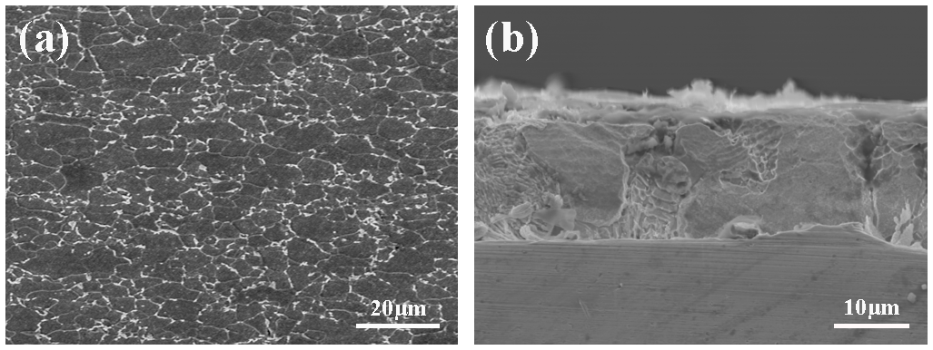
The matrix micromorphology and the coating cross-section morphology are also shown in
Figure 1. The mechanical properties and matrix microstructure of the two kinds of steel plates are almost consistent. In addition, the matrix microstructure of both is composed of ferrite and a small amount of pearlite. The differences only lie in the presence of Zn-Al-Mg coating.
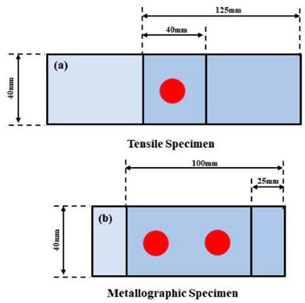
The two experimental steel plates were cut and processed into several 125 mm × 40 mm plate samples, and the processed samples were cleaned and dried with ethanol (99.5%) to avoid the metallurgical contamination of the spot-welding experiment by oil pollution and other factors. The cleaned samples were tested for spot-welding experiments under the lap state, as shown in
Figure 2, and the tensile samples and metallographic samples were prepared. In addition, the metallographic samples were welded twice, and a spot-welding experiment was carried out on the OBARA SIV21 small original spot-welding machine.
The tensile shear force of the spot-welding samples was measured by the SANS microcomputer servo-controlled hydraulic universal testing machine with a tensile speed of 2 mm/min. The rectangular samples (15 mm × 7.5 mm) of the metallographic and scanning samples were prepared from the spot-welding joints. The corrosion solution was 4% nitrate alcohol solution, and the corresponding corrosion time was 14 s. Then, the Leica DM 2000 microscope and TESCAN VEGA3 tungsten filament scanning electron microscope were used to observe the metallographic and scanning section of the welding joint. The micro-hardness value was measured with the HXS-1000AKY hardness meter (300 g, 10 s), and its micro-hardness distribution was measured along the horizontal and vertical direction of the welding joint.
Firstly, welding current, welding time and electrode loading were chosen as variables to design the orthogonal experiment. Then, mechanical properties and spot-welding joint parameters (pressure down rate, welding joint diameter, welding joint thickness) were measured systematically. Furthermore, the splash degree was assessed according to the vast amount of splash distance generated in the spot-welding process, and the splash size was graded in a section of 50 cm. The A/B/C/D splashes were, respectively, represented by splash distances of 150–100 cm; 100–50 cm; 50–0 cm; and no splash. The value range of welding current, welding time and electrode loading was preliminarily selected according to the thickness, strength and galvanizing layer of the plate and combined with previous tests and related documents (the current = 8–11 kA, the time = 12–18 cycles (1 cycle = 0.02 s), the electrode loading = 1.8–3.0 kN). The optimal welding parameters of HC340LAD + ZM were obtained through the orthogonal experiment, then the welding current and electrode loading of two kinds of steel, HC340LAD + ZM with Zn-Al-Mg coating and HC340LA without coating, were fixed under the optimal parameters. Taking welding time as the main variable, the nucleation process of the spot-welding joint of two kinds of steels and the effect of coating on the properties of the spot-welding joint were explored, and the change in corrosion resistance before and after welding was studied. The welding joint and the unwelded body material with the optimal welding parameters of 10 kA, 14 cycles and 2.6 kN for HC340LAD + ZM steel with Zn-Al-Mg coating and HC340LA without coating were selected, and three sets of 15 mm × 15 mm samples were prepared with wire cutting. Then, the polarization curve was tested after alcohol cleaning, with a scanning speed of 2 mV/s.
3. Experimental Results
3.1. Orthogonal Experiments
Then, the orthogonal tests were designed, and the specific test process parameters are shown in
Table 2.
With tensile shear as the main parameter, the mechanical properties of joints under each group of parameters were inserted into SPSS for multi-factor variance and extreme difference analysis, and the optimal process parameters were as follows: welding current, welding time and electrode loading were 10 kA, 14 cycles and 2 kN, respectively; the order of the influence of the three factors on tensile shear was current > pressure > time.
3.2. Macro- and Micro-Morphology
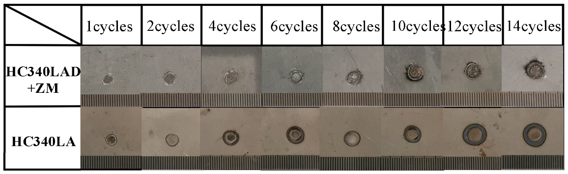
According to the orthogonal experiment results, the optimal welding process parameters were as follows: welding current, welding time and electrode loading were 10 kA, 14 cycles and 2 kN, respectively. Then, the two kinds of steel with coating and without coating were welded separately on the basis of the optimal welding process parameters by fixing the welding current and electrode loading and by changing the welding time to explore the dynamic nucleation process of the spot-welding process and the influence of the coating on the nucleation quality of the welding joint. The macroscopic morphology of the welds under different welding times is shown in
Figure 3. With the increase in welding time, the diameter of the welds of the two plates of steel also increased. In addition, with the increase in welding time, the HC340LA steel without coating showed a better quality welding spot surface without splash, while HC340LAD + ZM steel with coating had rough joints on the welding spot surface with fluctuations. Furthermore, the splash phenomenon appeared after 10 cycles, and the center of the welding point became yellow.
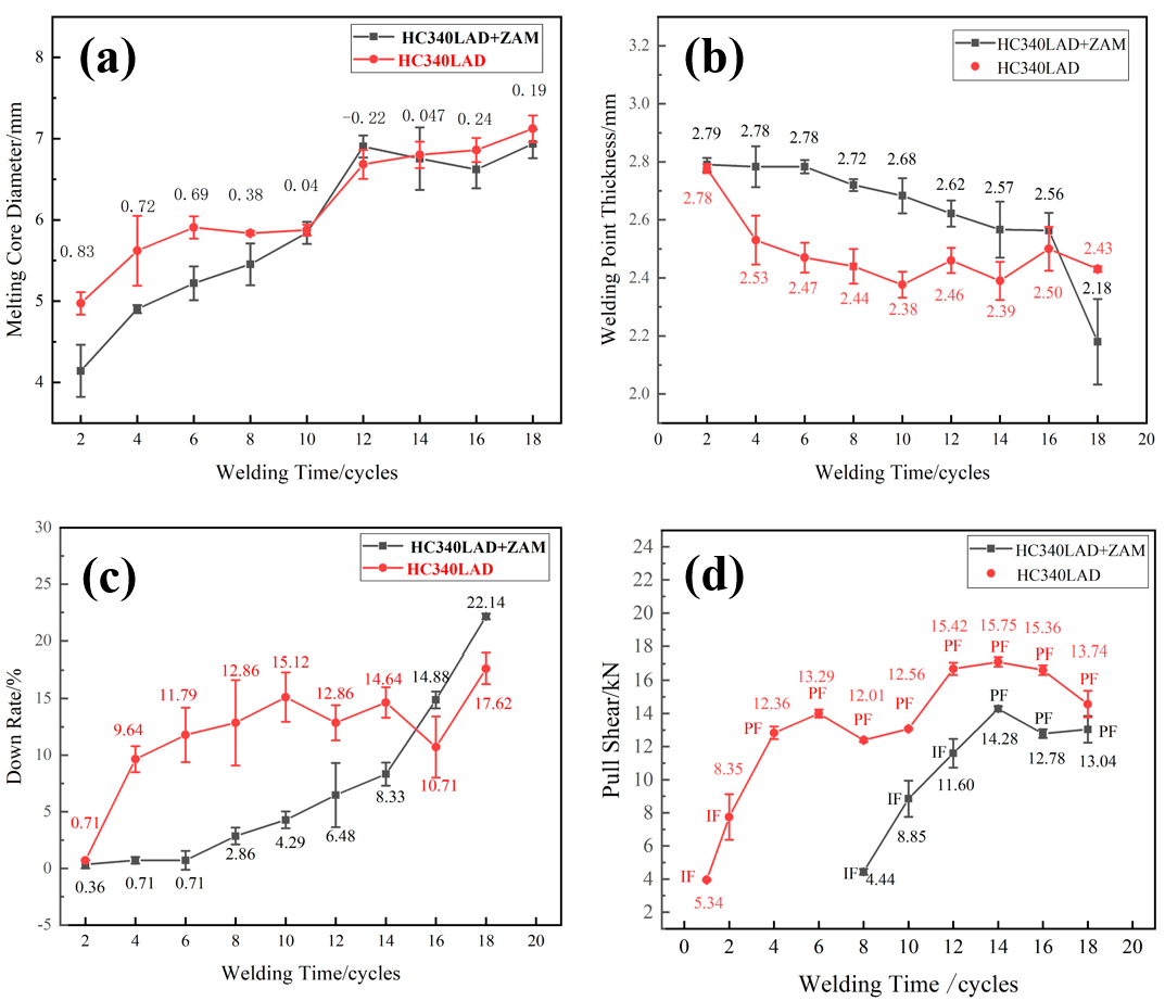
Figure 4 shows the change in the welding joint’s diameter, thickness, pressure down rate and tensile shear force with welding time. It can be clearly seen from
Figure 4 that the joule heat and the welding joint diameter of HC340LAD + ZM and HC340LA increased with the increase in welding time. When the welding time was one cycle, the welding joint diameter of HC340LA without coating was 0.83 mm larger than that of the HC340LAD + ZM steel with coating. With the increase in welding time, the gap in the welding joint diameter became smaller. When the welding time was 10 cycles, the welding joint diameter was almost the same, and then the increase in the welding joint diameter tended to be flat, while the thickness of the welding points was the opposite, and the thickness of both plates of steel showed a downward trend. When the welding time exceeded 14 cycles, the welding point thickness of the two plates of steel tended to coincide. The welding joint thickness of the 16 cycles was 2.56 mm and 2.5 mm, respectively. The corresponding downpressure rate was 14.88% and 10.71%.
Figure 4d shows the tensile shear force of HC340LA steel without coating and HC340LAD + ZM steel with Zn-Al-Mg coating. As the welding time increased, the tensile shear force rose first and then decreased, reaching its maximum after 14 cycles with the tensile shear forces of 14.28 kN and 15.75 kN. However, the tensile shear force of HC340LA steel without coating was higher than that of HC340LAD + ZM steel with Zn-Al-Mg coating under the same welding parameters. When the welding time of HC340LA without coating was one cycle, the welding core had already appeared, and the tensile shear force at this time was 5.34 kN. HC340LAD + ZM with coating did not nucleate until the welding time was eight cycles, and the corresponding tensile shear force was 4.44 kN. Combined with the diameter and the thickness of the welding point, the existence of the Zn-Al-Mg coating reduced the weldability. Although the diameter of the welding point was large enough after six cycles, an effective welding core was still not formed at this time. Because of the existence of Zn-Al-Mg coating, the contact resistance between the two plates was smaller, and there was less heat input from the welding center area, thus failing to effectively form the welding core. Therefore, with the increase in the welding time, the impact of the coating on the welding time became smaller, and HC340LAD + ZM with coating did not nucleate until the welding time was eight cycles. Meanwhile, the zinc with a low melting point evaporated and gasified the heat during welding, which reduced the effective heat input generated during welding, resulting in more difficult nucleation.
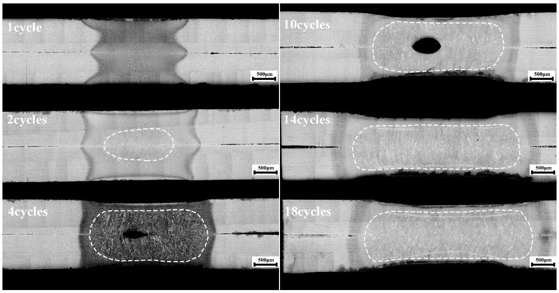
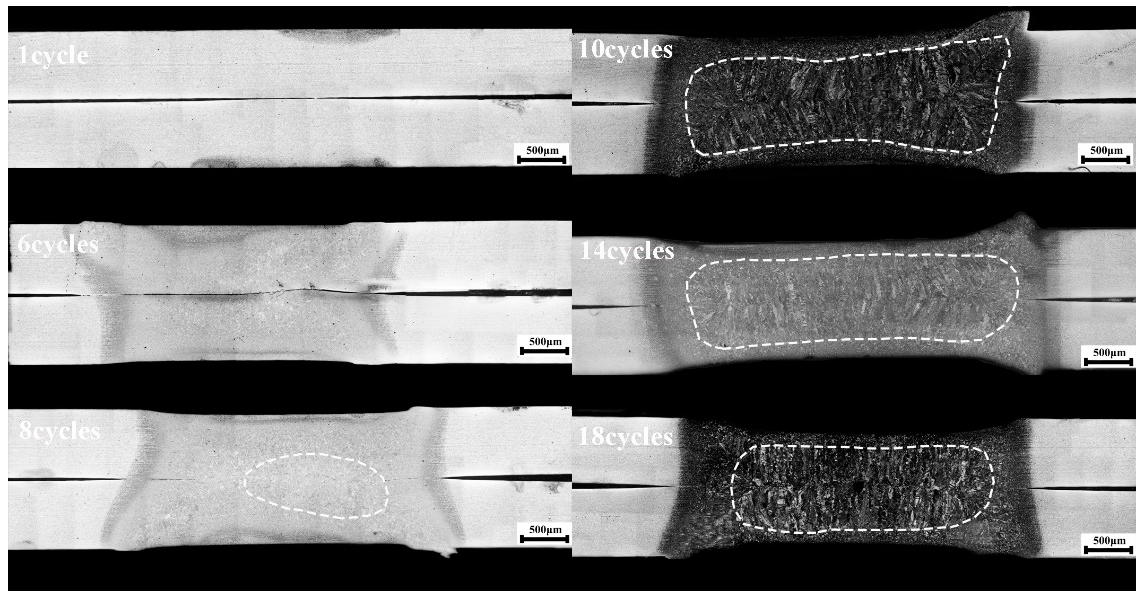
Figure 5 and
Figure 6 show the cross-section morphologies of the HC340LA without coating and the HC340LAD + ZM with coating at different welding times.
Figure 5 shows the cross-section morphology of HC340LA steel without coating when the welding time was 1~18 cycles. As shown in the figure, the uncoated HC340LA steel was very sensitive to the change in welding time, and the width of the molten core gradually increased with the increase in welding time, and the thickness of the welding point also decreased. When the welding time was one cycle, there was no complete nucleation, but a union appeared between the plates. When the welding time was two cycles, the nucleation began to obviously appear, forming a small welding core area. After four cycles, nucleation completed, and the columnar crystal appeared obviously perpendicular to the plastic ring. At this time, a shrinkage hole defect appeared. Because there was so little molten metal, it shrank as it cooled, and holes formed. As the welding time increased, the height of the melting core decreased, and the width of the melting core also gradually increased, which was basically unchanged after reaching 14 cycles.
Figure 6 shows the cross-section morphology of the HC340LAD + ZM steel with coating when the welding time was 1~18 cycles. Due to the existence of the coating, the welding of the coated HC340LAD + ZM steel requires a greater welding heat input. On the one hand, the existence of the coating made the contact resistance between the plates smaller and made the heat input generated during welding lower, resulting in difficult nucleation. On the other hand, because of the low melting point of Zn, the main heat generated was first absorbed by the coating, resulting in less heat input obtained by the parent material, Fe, which could not effectively nucleate. Thence, nucleation appeared initially when the welding time was eight cycles; when the welding time reached 10 cycles, the welded joint nucleated completely.
3.3. Fracture Form and Hardness Distribution
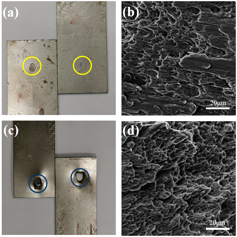
The failure modes of the welding point fracture of HC340LAD + ZM with Zn-Al-Mg coating and HC340LA without coating are mainly divided into two types: interface fracture (IF = interfacial failure) and pull-out fracture (PF = plug failure).
Figure 7a,b reveal the morphologies of IF macroscopic tensile shear fracture and IF fracture, respectively. The macroscopic fracture shows that the fracture occurred at the two interfaces of the welding point, while the morphology of the microscopic fracture is an obvious cleavage step.
Figure 7c,d show the morphologies of PF macroscopic tensile shear fracture and PF fracture, respectively. The macroscopic fracture illustrates that pull-out tear occurred in the parent material zone around the welding joint; the welding point was well fused, and no fracture occurred, while the morphology of the microscopic fracture had countless axial dimples.
According to
Figure 4d, due to the existence of coating, the HC340LAD + ZM steel did not nucleate at a low welding time. Nucleation completed after eight cycles, and the tensile shear force was 4.44 kN. In addition, the quality of the welding joint was poor, and the welding core was not firmly bonded. In this context, an IF-type interface fracture of the welding joint occurred. After 14 cycles, the quality of the welding joint nucleation was better, and the tensile shear force was 14.28 kN. At this time, a PF-type pull-out fracture occurred. The HC340LA steel without coating had good malleability due to the existence of no coating. After one cycle, although the plates did not melt in the process of chemical metallurgy at this time, the two plates combined under the action of electrode loading. At this time, the tensile shear force was 5.34 kN, and an IF-type interface fracture occurred. When the welding time was four cycles, a welding point with good quality formed, and a PF-type pull-out fracture occurred with a pull shear force of 12.36 kN. This was because, when the welding time was short, the two plates in the welding core area were not closely combined, and the shear force between the welding points was less than the tensile strength of the parent material. At this time, the fracture position occurred in the welding core. When the welding time was long enough, the welding heat was enough; the nucleation was complete, and the shear force of the welding core area was greater than the tensile strength of the parent material, thus, the pull-out fracture occurs. Under the same welding parameters, the tensile shear force of the welding joint with a Zn-Al-Mg coating was smaller than that of the welding joint without coating, which may owe to the existence of the coating, which affected the temperature and thermal cycle of the welding joint, resulting in the low tensile shear force.
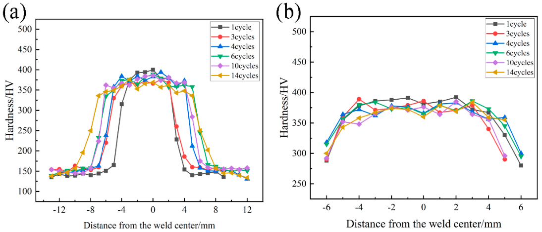
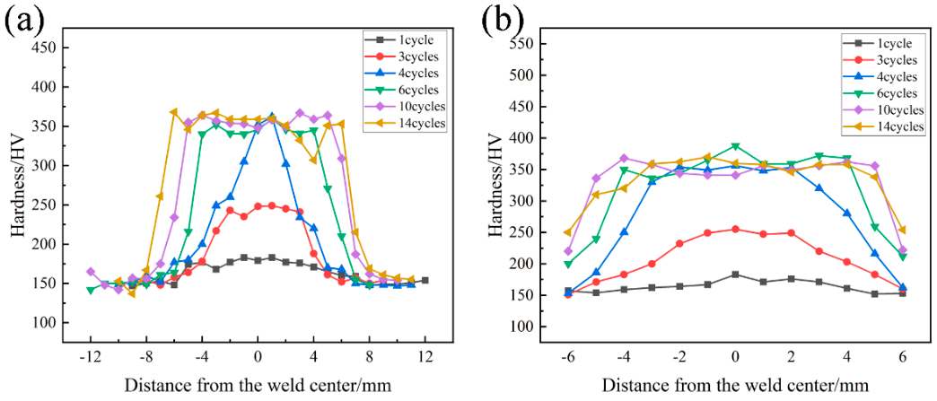
Figure 8 and
Figure 9 show the hardness value distribution of the welding point under different welding times for HC340LA without coating and HC340LAD + ZM with coating. As shown in the figure, the hardness value distribution of the welding points of both steel results in a “π”, high on both sides and low in the middle.
As can be seen in
Figure 8, nucleation occurred after one cycle, and even the obvious welding core zone, heat-affected zone and welding core zone appeared. The hardness value of the parent material was 150 HV; the average hardness of the welding core zone was 375 HV, and the hardness value of the heat-affected zone was between the two. In the horizontal direction, it is obvious that the welding core zone widened as the welding time increased. In the vertical direction, it was distributed high on both sides and low in the middle, and the hardness value near the electrode head was 280~300 HV.
As shown in
Figure 9, after one cycle and three cycles, the peak temperature of the welding point did not exceed the A
3 line, and the tissue of the welding core zone was mixed with martensite and ferrite. At this time, the hardness value of the central position was low (180 HV). After four cycles, the temperature of some areas near the welding core area exceeded the A
1 line, and a small amount of martensite formed. In this condition, the hardness value of the welding core zone reached 250 HV. After six cycles, on the one hand, due to the influence of the coating, there was no effective connection between the plates, but at this time, the welding core zone was completely austenitic, and a large number of martensite was obtained. In addition, the hardness value rose. On the other hand, due to the existence of the coating, the mechanical properties of the welding joints deteriorated, and the average hardness value of the welding core zone was 355 HV, which was lower than that of the welding joints of HC340LA without coating. In the vertical direction, the hardness value near the two sides of the electrode cap was 240 HV, which was lower than that of the welding joint of the HC340LA without coating (280 HV). This is because, during welding, the surface coating evaporated, splashed and took away the heat; thus, the surface area obtained less heat, eventually forming less martensite, and it had a lower hardness value.
3.4. Corrosion Behaviour Study
The results of the polarization curves for each zone are shown in
Figure 10 and
Table 2.
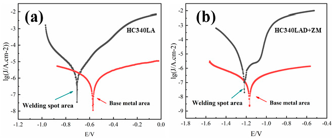
According to
Figure 10 and
Table 3, compared with the parent material and the welding point polarization curve of the same material, the corrosion potential of the welding point was lower than that of the corresponding parent material, which illustrates that the corrosion tendency of the welding point was greater than that of the body material, and the change in corrosion current was also consistent. The corrosion currents of the body material and the welding joint of the HC340LA steel without coating were 4.258 × 10
−4 mA·cm
−2 and 3.602 × 10
−3 mA·cm
−2. The corrosion current decreased by 8.46 times, while the corrosion currents of the parent material and the welding joint of the HC340LAD + ZM with Zn-Al-Mg coating were 5.934 × 10
−5 mA·cm
−2 and 1.323 × 10
−4 mA·cm
−2. The corrosion current decreased by 2.23 times. This is because the welding heat input increased in the welding process, which led to tissue transformation and the loss of the surface coating of the welding point during the welding process, thus leading to the deterioration of corrosion resistance.
The corrosion potentials of the HC340LAD + ZM base material and the welding joint containing zinc aluminum magnesium coating were (−1.167 V) and (−1.218 V), respectively; the corrosion potentials of the base material and the welding joint of HC340LA without coating were (−0.5721 V) and (−0.705 V), respectively. According to the longitudinal comparison, the HC340LAD + ZM had a lower corrosion potential at both the base material and the welding joint, so its corrosion tendency was greater. The corrosion current was just the opposite. The corrosion currents of the parent material of the zinc–aluminum–magnesium-coated plate and the uncoated plate were 5.934 × 10
−5 mA·cm
−2 and 4.258 × 10
−4 mA·cm
−2, respectively. The corrosion current of the zinc–aluminum–magnesium plate was 7.17 times that of the uncoated plate. The corrosion currents of the welding joint of the zinc–aluminum–magnesium-coated plate and the uncoated plate were 1.323 × 10
−4 mA·cm
−2 and 3.602 × 10
−3 mA·cm
−2. The gap in the corrosion current was 27 times greater. The reason why the corrosion potential of the Zn-Al-Mg-coated plate was higher than that of the uncoated plate and the corrosion current was smaller is that the corrosion of the Zn-Al-Mg-coated plate was the first to develop surface corrosion. The coating was mainly zinc, whose corrosion potential is higher (−1 V), and the uncoated plate was the corrosive matrix ferrite (−0.4 V). Due to the presence of primary crystal phase Zn; Al; MgZn
2; binary co-crystal tissue Zn/MgZn
2; and ternary co-crystal tissue Zn/MgZn
2/Al in the zinc–aluminum–magnesium coating—in which MgZn
2 and Mg
2Zn
11 had higher microhardness, better compactness and better single-phase corrosion resistance—the zinc and aluminum magnesium plates had higher corrosion potential, but a slower corrosion rate [
28,
29,
30].
4. Conclusions
(1) The orthogonal tests showed that the optimal parameters of HC340LAD + ZM steel resistance spot-welding are as follows: welding current, welding time and electrode loading were 10 kA, 14 cycles, and 2.6 kN, respectively. The influence of welding current, welding time and electrode loading on the tensile shear force can be successively ranked as current > pressure > time.
(2) When the fixed welding current (10 kA) and the electrode loading (2.6 kN) increased, the welding point diameter of both steel plates also increased as the welding time increased. Under the same welding parameters, the mechanical properties of the spot-welding joint of the HC340LA steel without coating were slightly better than those of the HC340LAD + ZM with coating. The HC340LA steel without coating began to nucleate after one cycle, and the tensile shear force was 5.34 kN. The nucleation completed after four cycles, and the tensile shear force reached 12.36 kN. The HC340LAD + ZM with coating started to nucleate after eight cycles, and the tensile shear force was 4.44 kN.
(3) In the nucleation test, the tensile shear force of the welding joint of the HC340LA steel without coating was greater than that of the welding joint of the HC340LAD + ZM steel with zinc–aluminum–magnesium coating. The tensile shear forces of the zinc-and-magnesium-coated steel and the uncoated steel increased first and then decreased as the welding time increased, and the tensile shear reached the maximum after 14 cycles. At this time, the tensile shear forces of the welding joint of the zinc-and-magnesium-coated steel and the uncoated steel were 14.28 kN and 15.75 kN, respectively.
(4) The fracture modes of the welding joint of the two kinds of steel can be divided into two types: pull-out fracture and interface fracture. When the welding time was short, and the heat input was small, the nucleation of the welding joint was insufficient, and the tensile shear force was small. Then, an interface fracture occurred. When the welding time increased, and the heat input increased, the nucleation of the welding joint was fully complete, and the tensile shear force exceeded 11.6 kN. At this time, the welding joint was pulled and broken at the parent material near the heat-affected zone.
(5) The hardness of the welding point of the uncoated steel and the coated steel was distributed in a “π” shape, which was high on both sides and low in the middle. The HC340LA steel without coating completed nucleation after one cycle, and the corresponding hardness values of the parent material and the welding joint were 150 HV and 375 HV. However, the hardness value for the HC340LAD + ZM steel with coating was very low after one and two cycles, and the hardness values of the welding core zone were 180 HV and 250 HV, respectively. A large number of martensite appeared in the center of the welding point after four cycles, and the hardness value of the welding core zone reached 355 HV. Compared with the hardness value of the welding joint of the HC340LA steel without coating and the HC340LAD + ZM steel with coating, the hardness value in the welding core zone and near the surface of the welding joint was higher than that of the same area with the coating.
(6) The corrosion resistance of the welding point was lower than that of the parent material. The corrosion current of the HC340LAD + ZM with zinc–aluminum–magnesium coating was 2.23 times that of the parent material, and the corrosion current of the welding joint of the HC340LA without coating was 8.46 times that of the parent material. The corrosion current of the welding joint of the zinc–aluminum–magnesium-coated steel was 27 times that of the welding joint of the uncoated steel, while the corrosion current of the parent material of the zinc–aluminum–magnesium-coated plate was 7.17 times that of the uncoated plate.


