
Estimation of Thermal Radiation in Bed Mattresses

1
Fire Insurers Laboratories of Korea, 1030, Gyeongchung-daero, Ganam-eup, Yeoju-si 469881, Korea
2
Department of Global Fire Science and Technology, Graduate School of Science and Technology, Tokyo University of Science, Chiba 278-8510, Japan
3
Department of Architecture Engineering, Chosun University, Gwangju 61452, Korea
*
Author to whom correspondence should be addressed.
Appl. Sci. 2022, 12(21), 11099; https://0-doi-org.brum.beds.ac.uk/10.3390/app122111099
Submission received: 6 October 2022
/
Revised: 29 October 2022
/
Accepted: 30 October 2022
/
Published: 2 November 2022
(This article belongs to the Special Issue Advanced Analysis and Technology in Fire Science and Engineering)
Abstract
:The population density of cities has been increasing with time and the development of industry. Building fires in large cities with high population density cause extensive human and property damage. To prevent such damage, the characteristics of flames such as the thermal radiation and intensity of the fire source must be considered when designing building structures. However, the consideration of these factors is practically inadequate. Accordingly, in this study, when a mattress was ignited in an open environment at a different installation height (0–515 mm), the measurements from a heat flux meter and the calculated thermal radiation were compared, and a comparative analysis was conducted using the existing prediction formulas by researchers described in ISO 24678-7. We examined the fire risk of mattresses according to the mattress installation height. As a result, the fire risk of the mattress was confirmed according to the mattress installation height; upon comparing the experimental and calculated values for radiant heat, it was found to be necessary to estimate the radiant heat using a calculation method that applies the configuration factor differently depending on the change in the flame shape. In addition, as a result of substituting the experimental value into the calculation method of ISO 24678-7 (a method for estimating the radiant heat of liquid combustibles), the experimental value and the calculated value were found to be significantly different. Therefore, similar to ISO 24678-7 for the radiation heat estimation method for “liquid combustibles”, an international standard for establishing the radiation heat estimation method for “solid combustible materials” as a standard was also required for a reasonable analysis of the fire safety phenomenon of solid materials, such as bed mattresses.
1. Introduction
In current times, industries are developing, building materials are becoming more diversified and customized, and the population density of cities is increasing, leading to more frequent accidents. Particularly, building fires in large cities with high population density can cause extensive damage in a single accident. Moreover, when designing buildings, the thermal radiation generated in a fire and the intensity of the fire source are not estimated in advance, and design measures to reduce the impact of flames on the surroundings are not considered. As such, governments and organizations related to fire protection and safety are dedicating efforts and steadily developing technologies to prevent accidents and minimize damage from fires, but their implementation is inadequate in practice.
The thermal radiation emitted by a flame is an important parameter that determines the flame’s future conditions, and the thermal radiation loss can lead to fire extinguishment [1]. In a fire, thermal radiation is generated from flames; moreover, research on heated architectural members, the smoke layer, and thermal radiation is underway. For example, when measuring the amount of radiation generated by a fire source in a compartment, Harada estimated thermal radiation by considering not only the thermal radiation of the flame itself but also the thermal radiation feedback generated from the ceiling, walls, and the smoke layer [2]. Additionally, to estimate the constant of the radiative fraction in turbulent fires, McCaffrey and Cox obtained the radiative fraction constant from methane burning [3], Koseki estimated the radiative fraction constant from liquid fuel through experiments [4], and Tewarson obtained the flame radiative fraction constant from burning solid materials [5]. Furthermore, Modan [6] calculated thermal radiation using the flame height equation of Thomas [7] in a windless environment, and Shokri [8] estimated thermal radiation using the flame height equation of Heskestad [9]. Based on these prior research results, in ISO 24678-7, the existing thermal radiation estimation models are applied based on constituent factors for estimating thermal radiation (the combustion area and the heat release rate) to establish the thermal radiation estimation algorithm as an international standard [10].
Meanwhile, the Korean market for bed mattresses (hereinafter referred to as mattresses) that are widely used in residential spaces has grown at an annual average of 17.17%, from KRW 211.5 billion in 2014 to 398.6 billion in 2018, and is projected to reach KRW 589.8 billion in 2023 [11]. The frequency of mattress-related fires increases with the growth of the mattress market. Mattress-based fires in South Korea were responsible for an annual average of 312 deaths over the past five years (2015–2019), with bedrooms being the most common place of death, with an average of 70 people (22.4%) [12]. In the United States, it was reported that half of the deaths and injuries caused by bedroom fires were due to mattresses and bedding, and one-third of bedroom fires were related to mattresses and bedding [13,14,15]. Hence, the fire risk of mattresses increases as the mattress market grows, but there is low public awareness of the risk, and sufficient preventive measures based on scientific findings have not been established yet.
Accordingly, this study confirmed thermal radiation measurements through a real-scale model experiment on mattresses at different installation heights and compared the experimental results and the predicted calculation results. Specifically, when a mattress was ignited in an open environment at different installation heights (0–515 mm), the measurements from a heat flux meter and the calculated thermal radiation were compared, and a comparative analysis was conducted using the existing prediction formulas described in ISO 24678-7.
2. Full-Scale Fire Test
In this study, a mattress experiment was conducted following the procedure of Park et al. [16], and their experiment was reproduced first to increase the accuracy of the data.
2.1. Test Specimen and Experimental Location
The mattresses used in this experiment were Japanese pocket coil mattresses made of cotton, polyester fabric, urethane foam, and coil (970 mm wide, 1960 mm long, and 230 mm high). The surface is made of cotton, and the inside is made of polyester, urethane foam, and coil. The total weight of the mattresses is 25.81 kg.
The experiment was performed in an open space (5 m width × 5 m depth × 2.7 m height) under a hood of a furniture calorimeter. To accurately measure the heat release rate (HRR), fireproof curtains were installed at the bottom of the hood to approximately 1.5 m from the floor (Figure 1).
2.2. Ignition Method
The burner for ignition was manufactured and used via the same method as in ISO 12949 [17]; it consists of an upper burner (12.9 L/min, 18 kW, burning for 70 s) and a lower burner (6.6 L/min, 9 kW, burning for 50 s), and it was moved immediately after the completion of combustion.
2.3. Mattress Installation Height
The specimen was installed, such that the heights of the bottom of mattresses (HB (mm)) were 0 mm, 115 mm, 215 mm, 315 mm, and 515 mm. For HB = 0, a calcium silicate board was placed on the floor, onto which the mattress was placed. For HB = 115, a calcium silicate board, steel frame (height of 115 mm), and mattress were installed in that order, and the space between the bottom of the mattress and the calcium silicate board was 115 mm. For HB = 215, 315, and 515 mm, the height was adjusted using 100 mm thick concrete blocks at the four corners of the frame. The combustion tests of the mattress were conducted as a single test for each condition of HB.
2.4. Measurement Item
The experimental measurements of the HRR, the flame height, and the heat flux in the mattresses of different heights were compared and analyzed.
The oxygen concentration, flow rate, and temperature of exhaust gas in the duct were measured using a furniture calorimeter, and the heat release rate was calculated using Equation (1), based on the oxygen-consumption method [18].
where is heat release rate (kW), E1 is the amount of energy developed per consumed kilogram of oxygen (kJ/kg); is the mass flow in the exhaust duct (kg/s); is the molecular weight of oxygen (g/mol); is the molecular weight of air (actually the molar weight of the gas flow in the duct) (g/mol); is the ratio between the number of moles of combustion products including nitrogen and the number of moles of reactants including nitrogen (expansion factor); is the mole fraction of O2 in ambient air, measured on dry gases (−); is the mole fraction of CO2 in ambient air, measured on dry gases (−); is the mole fraction of H2O in ambient air; is the mole fraction of O2 in flue gases, measured on dry gases (−); and is the mole fraction of CO2 in flue gases, measured on dry gases (−).
The flame height was measured from the recordings of a video camera installed at the cross-section of the mattress. To measure the height before the experiment, a reference was set using a 5 m long rod, and continuous flames and intermittent flames were extracted from the video footage to obtain the average flame (Figure 2).
A heat flux meter was set at the same height as the upper surface of the mattress, the measurement direction was upward, and the meter was installed at a horizontal distance of 0.2 m and 1 m from the side of the mattress (opposite to the burner), for the measurement of thermal radiation (Figure 3).
3. Results
3.1. Heat Release Rate
Figure 4 shows the HRR data when the mattress burns with the ignited burner. According to the different installation heights from the floor to the bottom of the mattress, as the mattress installation height increased, the HRR increased, and the fire growth rate (from about 100 s to max HRR) also increased. In addition, according to the mattress installation height (HB = 0–515 mm), the time for the HRR to reach 1 MW was 275 s, 221 s, 204 s, 177 s, and 178 s; as the mattress installation height increased, the heat was released more strongly and rapidly, and the fire growth rates were higher at HB = 315 mm and 515 mm than at other installation heights. However, HB = 315 mm and 515 mm showed similar HRR and fire growth rate trends.
3.2. Flame Height
Figure 5 shows the measurements of average flame height (height from the floor) every 20 s after ignition (not measured for HB 115 mm and 315 mm). The flame height varied with the mattress installation height after 100 s. At HB 0 mm, the flame height gradually increased after 100 s and reached the maximum (2.30 m) at 260 s. At HB 215 mm, it rapidly increased by approximately 1.98 m at 120 s and reached the maximum (2.62 m) at 240 s. At HB 515 mm, it increased exponentially after 100 s and reached the maximum (2.99 m) at 180 s. Thus, as the mattress installation height increased, the flame showed a higher maximum height and reached the maximum height more rapidly.
3.3. Radiation from Flames
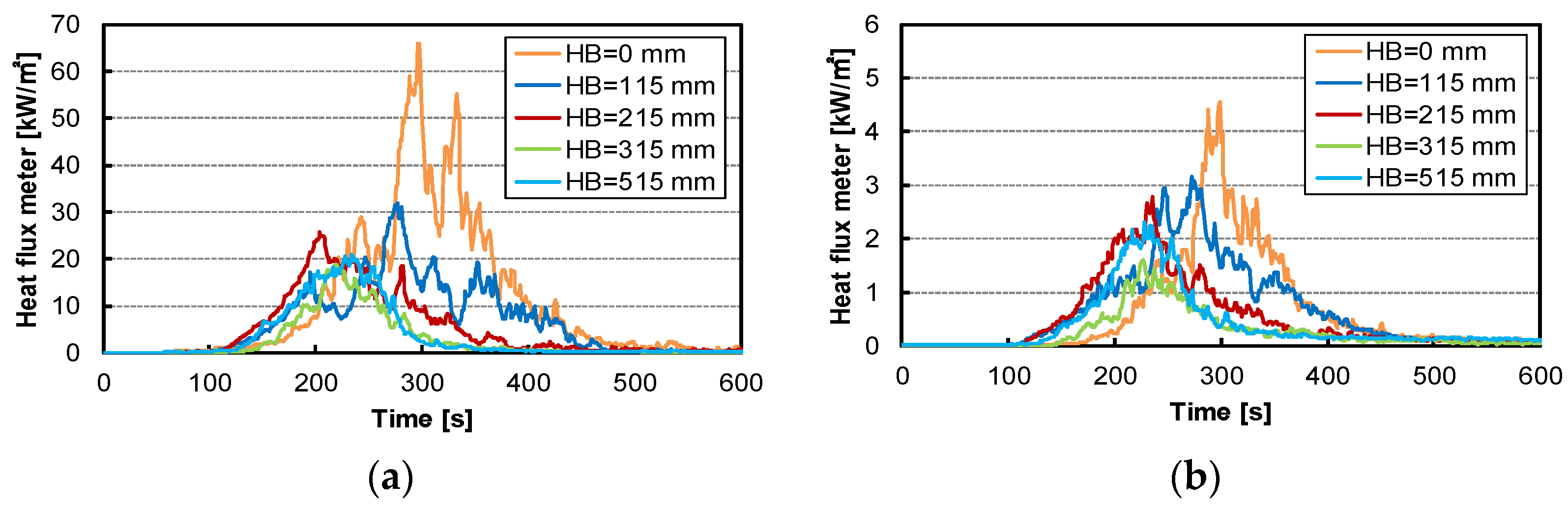
As described in Section 2.4, the heat flux meter was installed at 0.2 m and 1.0 m away from the side of the mattress, and the measurement results are shown in Figure 6. When the heat flux meter was installed at 0.2 m, for HB 0 mm, the maximum value was 66 kW/m2 at 298 s, and at other installation heights (HB 115–515 mm), the maximum values were approximately the same: 20–30 kw/m2 during the elapsed time between 200 and 300 s. For HB 0 mm, the mattress was installed on the floor, and the video footage showed that the flame was directed to the heat flux meter over time. This is because for HB 115–515 mm, when the mattress burns, the flame is directed upward by the air flowing under the mattress, while for HB 0 mm, the flame faces the direction of burning. When the installation location was 1.0 m, the peak value between 200 and 300 s was less than 5 kW/m2 and showed a similar trend overall.
4. Calculation of Radiation from Flames
In this section, the thermal radiation was calculated using the flame area and flame height measured from the video footage, and the results were compared with the experimental values. Moreover, we applied our experimental values to the thermal radiation estimation methods (the Mudan–Croce method and Shokri–Beyler method) described in ISO 24678-7 and conducted a comparison and analysis with vertical and horizontal targets at the same height as the flame base.
4.1. General
Thermal radiation is emitted by flames, and the released heat is transferred to arbitrary object surfaces. This thermal radiation is calculated by the atmospheric absorption rate, emissive power of a flame, and configuration factor. The general expression of thermal radiation is expressed as Equation (2). However, although the atmospheric absorption of thermal radiation is assumed to be homogeneous for τ (transmissivity), it is occasionally necessary to calculate the atmospheric absorption rate considering the absorption rate of water vapor and carbon dioxide. This study did not consider the effect of atmospheric absorption under the assumption that it was homogeneous.
where is the radiation heat flux to a target (kW/m2), is atmospheric transmissivity (−), E is the emissive power of a flame (kW/m2), is the configuration factor of a flame to a target (−), is emissivity, is the Stefan–Boltzmann constant given as 5.67 × 10⁻¹¹ (kW/m2·K4), T is the temperature (K), is the radiation absorption coefficient of a flame considering the diameter as the characteristic length (m−1), and l is the equivalent diameter of a flame (m) [19]. For calculating thermal radiation, various models have been developed to determine the configuration factor based on the flame heat source shape. The formula for calculating this configuration factor is slightly different for each scholar. In this study, we calculated the incident thermal radiation from the flame on the measuring surface of the heat flux meter, assuming the flame shapes formed on the upper part of the mattress (Figure 7a,b) through two methods, as described in the SFPE Handbook [5]. In addition, assuming the flame shape shown in Figure 7c according to the method of ISO 24678-7, two calculation methods in which the direction of the heat flux meter was horizontal and vertical, as well as the Mudan–Croce formula and the Shokri formula, were used to compare the results with experimental values. Finally, a relevant analysis was performed.
4.2. Calculation of Thermal Radiation Using Experimental Values
We measured the burning area and the flame height using video footage and obtained the configuration factors from the methods shown in Figure 7a–c. Then, those three individual values and experimental values were compared. The calculation process in Figure 7a is as follows:
where a is the height of the flame (m), b is the diameter of the combustion area (m), and c is the distance from the flame center to the thermometer (m).
The calculation process illustrated in Figure 7b is as follows:
where r1 is the radius of the combustion area (m), and r2 is the distance between the center of the flame (combustion area) and the target.
where h is the height of flame (m).
The calculation process in the vertical target of Figure 7c is as follows:
where is the height of the flame, and is the radius of the combustion area (m).
where is the distance between the center of the flame (combustion area) and the target.
The calculation process in the horizontal target of Figure 7c is as follows:
Figure 8 shows a comparison of the incident heat flux calculated based on the methods shown in Figure 7a–c and the experimental values (measured with the heat flux meter).
For HB 0 mm, Figure 7a shows a similar trend to Figure 7b,c for the horizontal target till 180 s but starts to show a difference at 200 s. Figure 7b,c show almost similar trends for the horizontal target, while Figure 7c shows a larger value for the vertical target than the other two methods. The maximum values were 15.69 kW/m2, 22.55 kW/m2, 29.48 kW/m2, and 22.55 kW/m2 at 260 s in the order of the legend from Figure 7a. Overall, the calculated value was larger than the experimental value, but the horizontal target in Figure 7b,c showed a similar pattern to the experimental value from 200 s.
For HB 215 mm, Figure 7a shows slightly larger values than the other calculated values up to 140 s, but from 200 s, it was relatively lower than other calculated values. Figure 7b,c show a similar trend horizontal target from 200 s, and Figure 7c shows that the trend for the vertical target steeply increased from 160 s to the maximum value, compared with other calculated values. Compared with the experimental values, the vertical targets in Figure 7b,c showed similar trends from 100 s to the maximum value.
For HB 515 mm, the vertical target in Figure 7a–c showed a similar trend from 100 s to 160 s, but from 180 s, Figure 7c shows a difference from Figure 7a–c, according to which the horizontal target value was relatively low up to 160 s, compared with the other calculated values, but it started to rise from 180 s and became similar to that observed in Figure 7b from 200 s. The maximum values were 15.98 kW/m2 (220 s), 23.03 kW/m2 (220 s), 29.45 kW/m2 (260 s), and 22.60 kW/m2 (240 s) in the order of the calculated values of the legend. Overall, compared with the experimental values, the horizontal target in Figure 7c showed a similar trend until 180 s, but from 220 s onward, the average values observed in Figure 7a–c became similar to the experimental values.
As a result, at HB 0 mm and 215 mm, the resulting values shown in Figure 7b,c, in which the shape of the flame is shaped into a cylinder, were similar to the experimental values. However, in HB 515 mm, the largest flame size, the calculated values were partially consistent with this experimental value.
4.3. Thermal Radiation Estimation Applied to ISO 24678-7
Two thermal radiation estimation methods described in ISO 24678-7 (the Mudan–Croce formula and the Shokri formula) were applied to the model equation using the combustion area and the heat emission data obtained by the experiment. The equation is as follows:
where As is the area of a pool fire source (m2), and D is the equivalent diameter of the flame (m).
where is heat release rate (kW), is the heat of combustion of fuel (J/g), and is the mass burning rate per unit area (kg/m2·s).
where is the mass burning rate per unit area of a sufficiently large pool (kg/m2·s), and k is the radiation absorption coefficient of a flame from various fuels (m−1).
- (1)
- Mudan–Croce formula
This model was proposed to estimate the thermal radiation generated from liquid fuel. For the flame height, the flame height data obtained in Thomas’ wood experiment was used; it can be applied within a pool fire diameter of 1–60 m. The emissive power equation is presented below, and the experimental results and calculated values are shown in Figure 9. Regarding the calculated values at an early stage of the flame, for 100 s, the emissive power is 0.9 kW/m2 at HB 0 mm, 2.7 kW/m2 at HB 215 mm, and 4.6 kW/m2 at HB 515 mm, indicating that as the mattress installation height increased, the thermal radiation tended to increase. The maximum values were 11.5 kW/m2 (240 s), 12.0 kW/m2 (220 s), and 12.4 kW/m2 (200 s) for HB 0 mm, 215 mm, and 515 mm, respectively, showing that it reached the maximum value earlier as the installation height increased. However, this confirmed a substantial difference between the calculated values and the experimental values.
where Emax is the emissive power of the luminous region of the flame (=140 kW/m2), is the emissive power of smoke (=20 kW/m2), and is the radiation absorption coefficient of the flame, considering the diameter as the characteristic length (=0.12 m−1).
- (2)
- Shokri’s Formula
The method based on Shokri’s formula is based on Heskestad’s flame height experiment and assumes that the flame has a cylindrical shape with a surface close to a blackbody and a homogeneous radiator on average. This method is effective when the heat flux is greater than 5 kW/m2 and is mainly used for LNG and JP-5 fuel and a combustion diameter of 1–50 m. Figure 10 shows the comparison of the experimental results. At the early stage of the flame, for 100 s, the emissive power is 0.9 kW/m2 at HB 0 mm, 2.5 kW/m2 at HB 215 mm, and 4.2 kW/m2 at HB 515 mm, indicating that as the mattress installation height increased, the thermal radiation tended to increase. Moreover, the calculated values became more gradual as the mattress installation height increased, and a large difference was observed between the calculated values and the experimental values.
5. Discussion
We confirmed the thermal radiation measurement results through an experiment under conditions of different mattress installation heights and subsequently compared them with the estimated thermal radiation values of ISO 24678-7.
As shown in Figure 8, near the maximum thermal radiation values, at HB 0 and 215 mm, the calculated values shown in Figure 7b,c, which were assumed by forming the shape of the flame into a cylinder, were closer to the experimental values. HB 515 mm confirmed the necessity of different calculation methods according to the growth of the fire. In addition, as mentioned in the method described in the SFPE Handbook, an experimental design was performed with the direction of the heat flux meter in the horizontal direction, but as shown in Figure 7c, in terms of thermal radiation values, the calculated result assuming the vertical direction was higher than the horizontally assumed calculation result. Therefore, when designing an experiment for fire risk evaluation, setting the heat flux meter’s direction to the flame direction and conducting an experiment is considered to be an appropriate method for fire risk assessment.
In addition, as shown in Figure 4, compared with HB 0 mm and 215 mm, the HRR for HB 515 mm rapidly increased, and the maximum value became large. Due to the nature of mattress fires, if there is a space under the mattress, melted material and some burning parts fall to the floor and burn. The higher the mattress installation height, the larger the flame due to the air flowing under the mattress, and these materials (that accompany the flame) promote the spread of flame in the mattress [20]. Consequently, the HRR and thermal radiation rapidly increase after a certain period of time. Therefore, a suitable method of predicting the flame shape is necessary. For example, if the flame spreads rapidly among solid combustibles, as in HB 515 mm, then the cross-application of the configuration factors according to changes in the flame shape can be used, where thermal radiation is calculated by assuming the flame shape of Figure 7a until a certain time, and subsequently, the configuration factor is determined as in Figure 7b, or the average value of Figure 7a–c Hor. can be applied.
Furthermore, the prediction formulas described in ISO 24678-7 output values were significantly different from the experimental values. Since the ISO 24678-7 formulas are for estimating thermal radiation from liquid combustibles, to apply them to solid combustibles, the international standard for solid combustibles must be established by calculating and applying the mass loss late, the effective heat of combustion, the heat release rate, and the combustion area through various experiments on solid combustibles.
6. Conclusions
In this study, we confirmed thermal radiation measurements through a real-scale model experiment on mattresses at different installation heights and compared the experimental and predicted calculation results. The results are as follows:
- ①
- When a fire occurs, if there is space under the mattress, the HRR, flame height, and thermal radiation may increase due to the fallen material accompanying the flame. Therefore, the results of this experiment based on different mattress installation heights provide information on the fire risk of mattresses.
- ②
- When calculating the thermal radiation of solid combustibles, when the HRR is high and the flame forms rapidly, an international standard for estimating the thermal radiation of a calculation method that applies different configuration factors according to changes in flame shape is also necessary.
- ③
- Although there are several techniques for estimating the thermal radiation risk, to apply them in practice, the type of combustible, the mass loss rate, the effective heat of combustion, the heat release rate, the combustion area, and the configuration factor must be suitably calculated.
- ④
- In the direction of the heat flux meter, as in the analysis result of this study, when designing an experiment for fire risk evaluation, it is considered to be an appropriate method for fire risk assessment to design the direction of the heat flux meter to face the flame.
This study examined the thermal radiation estimation methods for fires in an open space. The prediction of heat radiation for solid combustibles enables the estimation of the extent of flame spread, and the loss of heat radiation can lead to the extinction of flames. Therefore, it is absolutely necessary to establish an international standard for solid combustibles, as shown in the results of this study. Furthermore, as humans live in one space, if a fire occurs within a compartment, the risk is expected to increase due to thermal radiation from the smoke layer, the reflected emissivity from walls, and convective heat, in addition to direct radiation from the flames. As such, further research on estimating thermal radiation within a compartment is necessary.
Author Contributions
Conceptualization, K.-W.P., M.M., C.-G.C. and J.-J.J.; Data curation, K.-W.P. and J.-J.J.; Formal analysis, K.-W.P., M.M. and C.-G.C.; Funding acquisition, K.-W.P.; Investigation, J.-J.J.; Methodology, K.-W.P., M.M., C.-G.C. and J.-J.J.; Project administration, M.M.; Resources, J.-J.J.; Software, J.-J.J.; Supervision, C.-G.C.; Validation, K.-W.P. and M.M.; Visualization, J.-J.J.; Writing—original draft, K.-W.P.; Writing—review & editing, C.-G.C. All authors have read and agreed to the published version of the manuscript.
Funding
This research was funded by the National Research Foundation of Korea (NRF), grant number 2021R1A6A3A01086444, and by the Korea Institute for Advancement of Technology (KIAT) of Industrial Technology of the Ministry of trade, industry, and energy, Republic of Korea, grant number P162500261.
Institutional Review Board Statement
Not applicable.
Informed Consent Statement
Not applicable.
Data Availability Statement
Not applicable.
Acknowledgments
We would like to express our gratitude to Yoshifumi Omiya, Department of Architecture, Faculty of Science and Technology, Tokyo University of Science, for participating in this experiment and providing advice.
Conflicts of Interest
The authors declare no conflict of interest.
References
- Quintiere, J.G.; Lyon, R.E.; Crowley, S.B. An exercise in obtaining flame radiation fraction from the cone calorimeter. Fire Mater. 2016, 40, 861–872. [Google Scholar] [CrossRef]
- Shintani, Y.; Harada, K. A model for prediction of fire spread considering the effect of thermal feedback. J. Environ. Eng. Trans. AIJ 2009, 74, 759–766. [Google Scholar] [CrossRef] [Green Version]
- McCaffrey, B.J.; Cox, G. Entrainment and Heat Flux of Buoyant Diffusion Flames; NBSIR 82–2473; USDoC: Washington, DC, USA; NIST: Gaithersburg, MD, USA, February 1982.
- Koseki, H. Combustion characteristics of hazardous materials. In Proceedings of the Symposium for the NRIFD 56th Anniversary, Mitaka, Tokyo; National Research Institute of Fire and Disaster: Tokyo, Japan, 1 June 1998. [Google Scholar]
- Tewarson, A. SFPE Handbook of Fire Protection Engineering, 3rd ed.; National Fire Protection Association: Quincy, MA, USA, 2002. [Google Scholar]
- Mudan, K.; Croce, P.A. A Thermal Radiation Model for LNG Trench Fires; ASME Paper 84-WA/HT-75; ASME: New York, NY, USA, 1984. [Google Scholar]
- Thomas, P.H.; Baldwin, R.; Heselden, A.J.M. Buoyant Diffusion Flames: Some Measurements of Air Entrainment, Heat Transfer and Flame Merging. Symp. Int. Combust. 1965, 10, 983–996. [Google Scholar] [CrossRef]
- Shokri, M.; Beyler, C.L. Radiation from Large Pool Fires. J. Fire Prot. Eng. 1989, 1, 141–150. [Google Scholar] [CrossRef]
- Heskestad, G. Luminous heights of turbulent diffusion flames. Fire Saf. J. 1983, 5, 103–108. [Google Scholar] [CrossRef]
- ISO 24678-7; Fire Safety Engineering-Requirements Governing Algebraic Formulae-Part 7 Radiation Heat Flux Received from an Open Pool Fire. International Organization for Standards: Geneva, Switzerland, 2019.
- Park, Y.-S. ACE BED Technical Report, Korea Enterprise Data. 2021. Available online: https://ssl.pstatic.net/imgstock/upload/research/company/1626923221644.pdf (accessed on 5 October 2022).
- Fire Statistical Yearbook, National Fire Agency, 2015–2019. Available online: https://www.nfds.go.kr/bbs/selectBbsList.do?bbs=B21# (accessed on 5 October 2022).
- Ahrens, M. Home Fires That Began with Upholstered Furniture. National Fire Protection Association. 2008. Available online: http://www.nfpa.org/assets/files/PDF/UpholsteredExecutiveSum.pdf (accessed on 5 October 2022).
- Ahrens, M. Home Structure Fires. National Fire Protection Association. 2011. Available online: http://www.nfpa.org/assets/files/pdf/os.homes.pdf (accessed on 5 October 2022).
- Greene, M.; Miller, D. 2006–2008 Residential Fire Loss Estimates. Consumer Product Safety Commission Report. 2010. Available online: http://www.cpsc.gov/library/fire06.pdf (accessed on 5 October 2022).
- Park, K.W.; Kimura, K.; Mizuno, M.; Ikeda, K.I.; Ohmiya, Y.; Sugahara, S.I.; Hayashi, Y. Flame Spread Mechanism through Analysis of Fire Behavior of Bed Mattress by the ISO 12949 Test. J. Asian Archit. Build. Eng. 2015, 14, 725–732. [Google Scholar] [CrossRef] [Green Version]
- ISO 12949; Standard Test Method for Measuring the Heat Release Rate of Low Flammability Mattresses and Mattress Sets. International Organization for Standards: Geneva, Switzerland, 2011.
- Barbrauskas, V.; Grayson, S.J. Heat Release in Fires; Chapter 3; Elsevier Applied Science: Pittsburgh, PA, USA, 1992; pp. 31–44. [Google Scholar]
- Quintiere, J.G. Principles of Fire Behavior, 2nd ed.; CRC Press: Boca Raton, FL, USA, 2017; p. 86. [Google Scholar]
- Nazaré, S.; Davis, R.D.; Butler, K. Assessment of factors affection fire performance of mattresses: A review. Fire Sci. Rev. 2012, 1, 2. [Google Scholar] [CrossRef]
Figure 1.
Experimental setup of open space test: (a) arrangement of the test body (unit: mm); (b) photo in mattress test (HB = 515 mm).
Figure 1.
Experimental setup of open space test: (a) arrangement of the test body (unit: mm); (b) photo in mattress test (HB = 515 mm).

Figure 2.
Measurement method of flame height (HB = 515 mm).

Figure 3.
Installation position of heat flux meter (HB = 115 mm).

Figure 4.
HRRs of the mattresses under different installation conditions.

Figure 5.
Experimental results of the average flame height.

Figure 6.
Heat flux measured by the heat flux meters installed at the same height as the top surface of mattress with the measuring surface turn-up at the position of (a) 0.2 m and (b) 1.0 m away from the side of mattress.
Figure 6.
Heat flux measured by the heat flux meters installed at the same height as the top surface of mattress with the measuring surface turn-up at the position of (a) 0.2 m and (b) 1.0 m away from the side of mattress.

Figure 7.
Configuration factor geometry: (a) vertical rectangular flame shape; (b) cylindrical flame shape; (c) cylindrical flame shape indicated in ISO 24678-7.
Figure 7.
Configuration factor geometry: (a) vertical rectangular flame shape; (b) cylindrical flame shape; (c) cylindrical flame shape indicated in ISO 24678-7.

Figure 8.
Comparison of calculated values obtained using the methods illustrated in Figure 7a,b as the configuration factor with experimental values: (a) HB = 0 mm; (b) HB = 215 mm; (c) HB = 515 mm.
Figure 8.
Comparison of calculated values obtained using the methods illustrated in Figure 7a,b as the configuration factor with experimental values: (a) HB = 0 mm; (b) HB = 215 mm; (c) HB = 515 mm.

Figure 9.
Comparison of calculated values by Mudan–Croce formula with the experimental values: (a) HB = 0 mm; (b) HB = 215 mm; (c) HB = 515 mm.
Figure 9.
Comparison of calculated values by Mudan–Croce formula with the experimental values: (a) HB = 0 mm; (b) HB = 215 mm; (c) HB = 515 mm.

Figure 10.
Comparison of calculated values by Shokri’s formula with experimental values: (a) HB = 0 mm; (b) HB = 215 mm; (c) HB = 515 mm.
Figure 10.
Comparison of calculated values by Shokri’s formula with experimental values: (a) HB = 0 mm; (b) HB = 215 mm; (c) HB = 515 mm.

Publisher’s Note: MDPI stays neutral with regard to jurisdictional claims in published maps and institutional affiliations. |
© 2022 by the authors. Licensee MDPI, Basel, Switzerland. This article is an open access article distributed under the terms and conditions of the Creative Commons Attribution (CC BY) license (https://creativecommons.org/licenses/by/4.0/).
Share and Cite
MDPI and ACS Style
Park, K.-W.; Mizuno, M.; Cho, C.-G.; Jeong, J.-J. Estimation of Thermal Radiation in Bed Mattresses. Appl. Sci. 2022, 12, 11099. https://0-doi-org.brum.beds.ac.uk/10.3390/app122111099
AMA Style
Park K-W, Mizuno M, Cho C-G, Jeong J-J. Estimation of Thermal Radiation in Bed Mattresses. Applied Sciences. 2022; 12(21):11099. https://0-doi-org.brum.beds.ac.uk/10.3390/app122111099
Chicago/Turabian StylePark, Kye-Won, Masayuki Mizuno, Chang-Geun Cho, and Jong-Jin Jeong. 2022. "Estimation of Thermal Radiation in Bed Mattresses" Applied Sciences 12, no. 21: 11099. https://0-doi-org.brum.beds.ac.uk/10.3390/app122111099
Note that from the first issue of 2016, this journal uses article numbers instead of page numbers. See further details here.