
Design and Performance of L-CaPaMan2


1
LARM2 Laboratory of Robot Mechatronics, University of Rome Tor Vergata, 00133 Rome, Italy
2
The Rolls-Royce UTC in Manufacturing and On-Wing Technology, Faculty of Engineering, University of Nottingham, Nottingham NG8 1BB, UK
*
Author to whom correspondence should be addressed.
Appl. Sci. 2022, 12(3), 1380; https://0-doi-org.brum.beds.ac.uk/10.3390/app12031380
Submission received: 13 December 2021
/
Revised: 12 January 2022
/
Accepted: 21 January 2022
/
Published: 27 January 2022
(This article belongs to the Special Issue Dynamic Phenomena)
Abstract
:The improved solution of L-CaPaMan design is elaborated with solutions for low-cost lightweight features. A new prototype is presented as a result of design improvements by using market components and 3D printing manufacturing. The new prototype as L-CaPaMan (Light CaPaMan) is characterised with new components for a new slider solution and light-structure links. The prototype construction is discussed up to a testing layout for design validation and operation characterization. Results of testing are discussed to outline the operation performance of L-CaPaMan by using Arduino controller with basic sensors for motion and action monitoring.
1. Introduction
Parallel manipulators as a class have been developed as described in [1,2]. In comparison with serial manipulators, their closed-loop structures are more rigid and precise in positioning, because of the error compensation by others; the ability to reach high velocities and accelerations; and the reduced inertial characteristics for the same load, which can be reached by using lighter actuators. On the other hand, precision is constrained by the smaller workspace, and non-linear behaviour complicates kinematics.
Two main types of parallel manipulators are widespread: Gough-Stewart platform and Delta robots. The Gough–Stewart structure was developed as a tire-testing machine [3] and is widely used in different types of full flight [4,5] and drive simulators [6], imitating the movements of airplanes such as Boeing-707, Douglas DC-8, or car, respectively. The Taylor Spatial Frame [7] is an external fixture, based on the same architecture, used in orthopedic medicine for bone recovery or correction. The Hexapod telescope [8] uses the Gough–Stewart structure for positioning. Six actuators scheme is used in space-docking systems, such as the low-impact docking system [9]. The Delta robot has universal joints in its structure, which gives more mobility than the Gough–Stewart platform. However, its larger position workspace can be actively used for efficient industrial pick-and-place operations [10] where orientation control is not required. In RoboCrane [10], a Delta structure has been scaled for weldment operations for ship building. In medicine, it is used for assistance [11] or surgical operations [12].
Some other structures and schemes with different limb kinematic chains are built for solving field tasks. For example, the Cassino Parallel Manipulator, or CaPaMan, which was introduced in 1997 [13] is a different type of parallel structure. Its mechanics, described in [14,15], can be used for earthquake simulation [16] and in humanoid robots [17]. In combination with other structures and types, both serial and parallel, it has been used as end-effector in drilling machines [18] and surgical robots [19].
For all these structures, performance is the key factor, even though it affects the final cost of manufacturing, making high-performance robots expensive and difficult to manufacture. For study and research needs, daily use, or any other situation where users cannot afford to build an industrial-quality robot, reducing price and manufacturing complexity is critical. Even if educational-oriented robots are generally cheaper, their cost can be significant. For example, the price of DexTAR, a professional educational robot [20], is around 7000$. With the development of 3D printing and DIY kits for education robotics, such as Arduino board and its extensions, it has become possible to significantly reduce the price and entry level in robotics. The CaPaMan improvement from [21] is an example of using these technologies.
The L-CaPaMan, which is presented below, is a prototype for study and research tasks. While keeping the structure of the first prototype [13,14], new design features, such as rolling-bodies translational joint, are introduced, to increase the overall mechanism performance, which has been evaluated in dynamic simulation. The prototype has been assembled and tested in LARM2; the real system behaviour has been investigated to validate the results of the dynamic simulation.
2. CaPaMan Design and Requirements
The first CaPaMan prototype, shown in Figure 1a, introduced a new structure of parallel manipulators [13]. While keeping the same structure, its performance can be improved in different ways: increasing performance in terms of forces, speeds, and accelerations, or reducing the costs of manufacturing while keeping the performance parameters from the previous case. L-CaPaMan has been designed following the second path. In the original CaPaMan prototype, all the components are machined from metallic parts, and industrial-grade motors are required for operations. The following improvement from 2017 [21], which is shown in Figure 1b, kept this structure; with 3D printing development, it became possible and expedient to change the material of the mechanism to plastic. Smaller and cheaper motors could also be used to operate, because less torque is needed for the smaller masses. The manufactured translational joints of this prototype, however, are sliding bodies, with low performance due to high friction.
In L-CaPaMan, the translational joint is replaced with 3D-printed parts that enable rolling instead of sliding. The performance of this solution has been investigated in CAD simulation and by using sensors in real model. To estimate performance, the kinematic characteristics of the platform were considered. The total cost of manufacturing can be measured as a sum of prices of the components.
The requirements to the new design of mechanism are described here:
- Material of the parts: PLA
- Cost of manufacturing: less than 100€
- Mass: less than 1 kg
- Acceleration of the platform: more than 2 m/s2
3. CAD Design and Simulation
L-CaPaMan2 kept the structure of the first prototype. The scheme of the structure is shown in Figure 2a. The closed-loop parallel mechanism with 3 d.o.f. includes three limbs with rotational, translational, and spherical joints each. The input joint of each limb is the rotational joint at the base. The lengths of the links are marked as lji, where j is a part number and i is the limb number; lKi is a distance to point K on the translational joint, and lGH is a distance from the spherical joint to the central point of the platform H. Following this structure, a new prototype has been designed in Autodesk Inventor 2021 Professional [22], as presented in Figure 2b.
The proposed research aims at improving, with a low-cost and lightweight design, the previous L-CaPaMan. As such, the main impact of the reported work is a new L-CaPaMan that manages to achieve the same performance of the previous versions in a more compact form design. Table 1, with the design parameters of the robot, is added to the paper for a direct size comparison. The constraints to the lengths of the mechanism parts prevent collision between the parts. The previous design of the translational joint [23], which was also built with 3D-printed components, and the real tests [24] show that in some cases the joint fails due to disassembly. In the new solution, the translational joint must be protected from disassembling during operation. Finally, it must have three idle (rotational) d.o.f. to avoid redundancies and associated vibrations. Following these requirements, the model has been designed with the dimensions, listed in Table 1.
The translational joint has been redesigned for 3D-printing; the model structure is shown in Figure 3a. The joint includes two printed parts and three manufactured bearings, which are connected to the part by pins from PLA. In the complete assembly, two wheels are placed on the rail and called “top wheels” and one, which is called “bottom wheel”, is under the rail and constrains relative vertical movements.
Translational movements are restricted with the border on one side of the rail, and by the bottom wheel pin they make contact with the other part on the other side, as shown in Figure 3b. Although the rolling bodies are placed on one surface, the stability of the construction is provided by the borders for the wheels, with 0.1 mm tolerance h1 and a 0.5 mm gap h2 on each side of printed parts.
In order to analyze the behaviour of the designed system, dynamic simulation has been carried out with the parameters that are chosen and presented in Table 2 and Table 3.
From [25], the operating speed of the motor for 6 V power supply is 0.14 s/60 deg, and angular velocity ωn for the input motion in the simulation is obtained as 427.571 deg/s. The input joint for four-bar linkage in limbs moves from α −45 to 45 deg. A dry friction coefficient kdf has been set for the wheels in the prismatic joint of each limb. Stiffness and damping coefficients are marked as kst and kdamp, respectively. Time Δt is defined as the whole time of simulation divided by the number of scanning intervals.
Three modes of movement have been analyzed. The first mode shows a simultaneous motion of the limbs; in the second mode, motion of an individual limb is set; and in the third mode, the motion of the limbs with a phase shifting between each of them has been assumed. The plot in Figure 4 illustrates the scheme of the limb’s input joint motion in degrees. The plot has five characteristic points:
A: start moving from position −45 deg, t = t0
B: end moving in position 45 deg, t = t1
C: start moving from position 45 deg, t = t2
D: end moving in position −45 deg, t = t3
E: end of the simulation in position −45 deg, t = te
Figure 4.
A scheme for input motion mode of the limbs.

For dynamic simulation, it is required to define the time to reach ωn from ω = 0 and time to reach ω = 0 from ωn, this time has been defined as 0.1 s. Therefore, the whole time between points A–B and C–D is equal to 0.31 s. Table 3 describes motions of input joint for each limb in relation to time.
Figure 5 and Figure 6 show the behaviour of the system during the simulation in case of accelerations of the point H—central point of the platform. By controlling the speed, the accelerations values are also restricted and do not exceed 3 m/s2. With the simultaneous movements of legs in Mode 1, accelerations are observed only along Z axis. On the other hand, for Mode 3 the accelerations along Z axis are less than along others, as shown in Figure 6. When only one leg is moved, distance along Z axis is less than along others.
When the speed is the controlled characteristic, the torque depends on it. Figure 7a,b show the torque values changing during time. The measurements have been done for the first leg, which is placed perpendicularly to X axis.
Overall, the proposed L-CaPaMan design enables a lighter, smaller, and cheaper version of the L-CaPaMan when compared also to the 2017 and 1997 CaPaMan versions, as also shown in Table 1. Nonetheless, the kinematic performance of the novel mechanism, which is here expressed in terms of motion and acceleration, is comparable to the ones reported in previous works [18,22], with a peak acceleration of 3 m/s2 for the first CaPaMan prototype (1997, made of metal), 2.5 m/s2 for the first low-cost CaPaMan prototype (2017, made of 3D-printed parts), 2.3 m/s2 for the novel L-CaPaMan2.
4. Prototype Testing
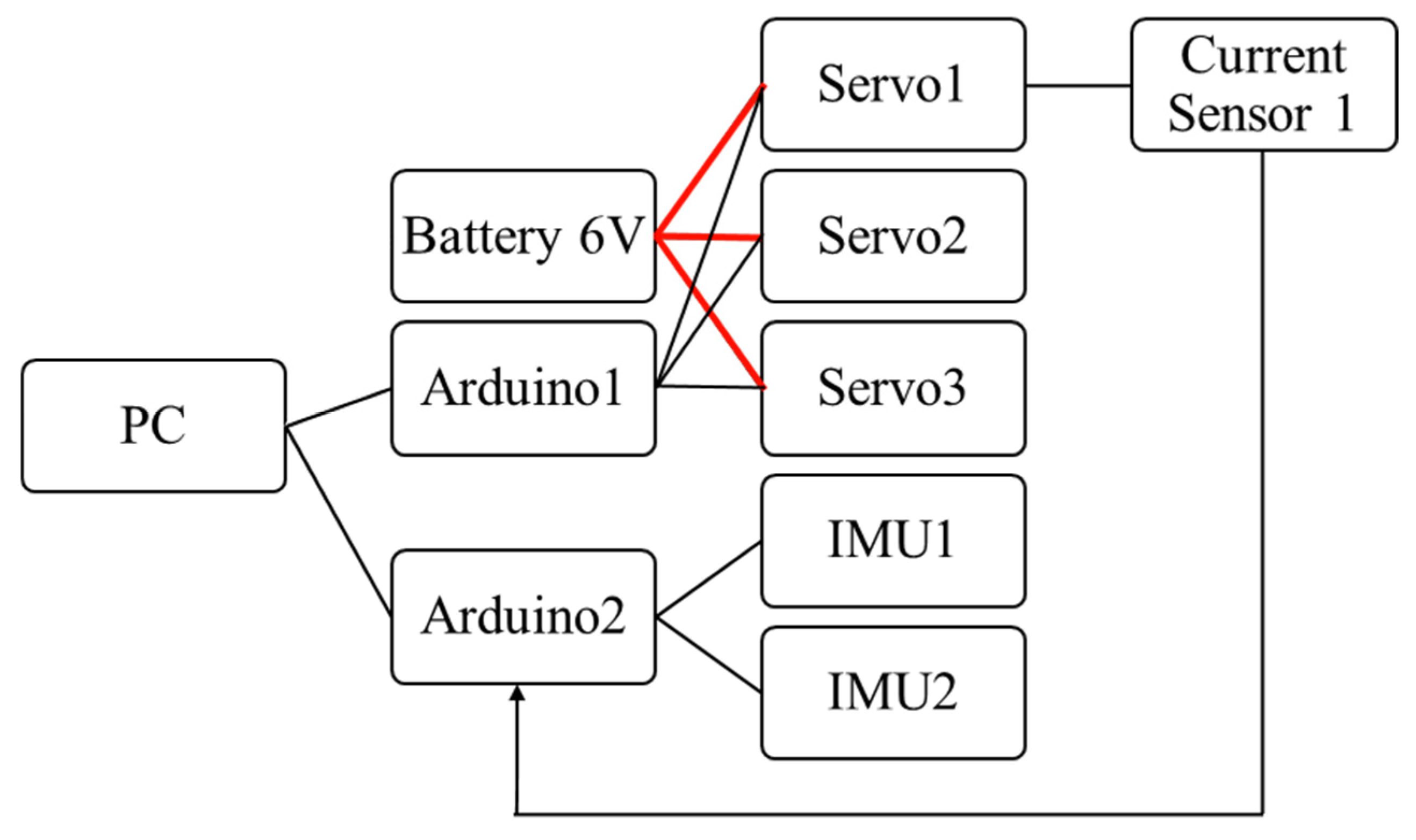
To check working feasibility, the prototype was assembled with 3D-printed and market components. Some parts from the previous work [23] were used. The assembled prototype is shown in Figure 8a. Design from Figure 2b was realised as a new part of the assembly. It is shown in more detail in Figure 8b. The control algorithm was not changed, and the original scheme of system design was preserved, as in Figure 9. The parameters of 3D printing for prototype components are listed in Table 4.
Using the online market RS components [26], the price table was compiled and presented as Table 5, assuming the availability of 3D printer and filament, required cables, and PC with preinstalled software.
The calculated price was more than required. In fact, almost all the components were in the LARM2 laboratory and used also for other projects; therefore, assembly of the mechanism cost less.
Testing was carried on following the modes, described in Table 3.
5. Testing Results
Before making tests, the workability of the system and its components has been checked. When the system is static, the IMU sensor measures not only its own accelerations, but also the gravitational component, so when it is placed in the horizontal position, the acquired acceleration data in m/s2 must be (0.0; 0.0; −9.806), where the last component represents the standard acceleration of gravity. The raw acceleration data conversion from the sensor is executed by the formula (1) from [27]:
where araw = (0 … 32768) is a value, acquired from sensor to Arduino board, and getAccRange = 2 is predefined by the user maximal acceleration in g = 9.806 mm/s2 standard acceleration of gravity. The results from IMU sensor shows that during a first test calibration in static horizontal position, the acceleration components data as (0.0; 0.0; −80.0) mm/s2 are different from expected ones. For that reason, it is needed to calibrate the sensor.
a = (araw/32768.0) ∗ getAccRange ∗ g,
To calibrate the sensor, it has been placed and statically fixed in the different positions, while acquiring the data. The acquired values of the accelerations must be zeros, except one of the components, which must be equal to 9.806 or −9.806 depending on the orientation. After zeroing the two components, the values of the third component have been taken 10 times, and the average has been calculated. Therefore, to equalise the measurements of the acceleration a to the standard acceleration of gravity, they must be multiplied by the coefficient k, which can be calculated such that k = 9.806/a.
By taking the experiments, the coefficients for x, y, and z components have been calculated. For given sensor BMI160, the coefficients are equal to 0.121965, 0.11744, and 0.12251, respectively. The coefficients may vary from the different examples of the sensors and accuracy of orthogonality to the ground while calibrating the sensor.
The acquired results for modes 1 and 3 in terms of acceleration of H are represented in Figure 10a,b, respectively. The acquired components of acceleration from the IMU sensor are represented with gravitation affect. For comparison of the results with the dynamic simulation model, each acquired value has been compared to the arithmetic average for all the results and the difference has been calculated. The maximal value of the component has been found from the data from IMU sensors and has been represented in Table 6.
Before acquiring the results, the presented model was tested near 100 times, installed, and reinstalled; components were tested together and separately. The characteristics of stiffness and tolerances for printed components were worse than for manufactured parts. Moreover, during the design and assembly process, the task was not set to make the most accurate and precise model. Because of the large tolerances, the rigidity of the assemble was lower than expected; printed bodies of translational joint displayed parasitic motions. The whole assembly in each test needs to be placed orthogonally to the ground. All these factors affect the acquired data. Low rigidity may cause micro-oscillations, which registered by the sensor with high accelerations.
6. Conclusions
The CAD model has been tested in dynamic simulations. It has been verified by the system while using imposed motion control by prescribed velocity. For the given parameters in dynamic simulations, the acceleration values mostly depend on the time to reach the maximum speed value. Other parameters such as the infill of the plastic parts, could be negligible. The computed results in the simulated operation are comparable with the data that are acquired from the sensors in testing the prototype. The assembled prototype has larger tolerances than the ones obtained by machine parts, in dimensions of parts and between parts, so that they cause the low rigidity of the assembly and affect the final results. The effect is shown in acquired results from the sensors, and results in terms of accelerations are comparable in qualitative and quantitative characteristics. The results could be improved by increasing the rigidity of the construction and reducing the tolerances, but the time of printing will be necessarily increased. The built low-cost model can be used for user-oriented tasks with satisfactory efficiency in accelerations of more than 2 m/s2 showing the feasibility and the efficiency of the proposed new solution with a new translational joint.
Author Contributions
Conceptualization, M.C. and A.T.; methodology, A.T. and M.R.; software, A.T.; validation, A.T., M.R. and M.C.; formal analysis, A.T.; investigation, A.T., M.R. and M.C.; resources, M.C.; data curation, A.T. and M.R.; writing—original draft preparation, A.T. and M.C.; writing—review and editing, A.T., M.R. and M.C.; visualization, A.T.; supervision, M.C.; project administration, M.C.; funding acquisition, M.C. All authors have read and agreed to the published version of the manuscript.
Funding
This research received no external funding.
Institutional Review Board Statement
Not applicable.
Informed Consent Statement
Not applicable.
Conflicts of Interest
The authors declare no conflict of interest.
References
- Tsai, L.-W. Robot Analysis: The Mechanics of Serial and Parallel Manipulators; John Wiley & Sons: New York, NY, USA, 1999. [Google Scholar]
- Gogu, G. Structural synthesis of parallel robots part 1: Methodology. In Solid Mechanics and Its Applications, Volume 149; Springer: Dordrecht, The Netherlands, 2008. [Google Scholar] [CrossRef]
- Tompkins, E. History of the Pneumatic Tyre; Eastland Press: Sudbury, UK, 1981; pp. 86–87. [Google Scholar]
- Huang, Y.; Pool, D.M.; Stroosma, O.; Chu, Q.P.; Mulder, M. A review of control schemes for hydraulic stewart platform flight simulator motion systems. In Proceedings of the 2016 AIAA Modeling and Simulation Technologies Conference, San Diego, CA, USA, 4–8 January 2016. [Google Scholar] [CrossRef]
- Campos, A.; de Faveri, G.; Schutel, C.; Neto, F.; Reis, A.; Garcia, A. Inverse Kinematics For General 6-RUS Parallel Robots Applied On UDESC-CEART Flight Simulator. ABCM Symp. Ser. Mechatron. 2014, 6, 456–464. [Google Scholar]
- Andrievsky, B.; Kazunin, D.; Kuznetsov, N.; Kuznetsova, O.; Leonov, G.; Seledzhi, S. Modeling, Simulation and Control of Pneumatically Actuated Stewart Platform with Input Quantization. In Proceedings of the UKSim-AMSS 8th European Modelling Symposium, Pisa, Italy, 21–23 October 2014; pp. 263–268. [Google Scholar] [CrossRef]
- Fadel, M.; Hosny, G. The Taylor spatial frame for deformity correction in the lower limbs. Int. Orthop. 2005, 29, 125–129. [Google Scholar] [CrossRef] [PubMed] [Green Version]
- Chini, R. The Hexapode Telescope—A Never-ending Story. Rev. Mod. Astron. 2000, 13, 257–268. [Google Scholar]
- LaBauve, T.E. Low Impact Docking System (LIDS). JSC-17710; 2009. Available online: https://ntrs.nasa.gov/citations/20090007783 (accessed on 12 January 2022).
- BostelMan, R.; Albus, J.; Dagalakis, N.; Jacoff, A. RoboCrane [R] Project: An Advanced Concept for Large Scale Manufacturing. In the Proceedings of AUVSI-PROCEEDINGS, 15–19 July 1996; pp. 509–522. Available online: https://tsapps.nist.gov/publication/get_pdf.cfm?pub_id=820568 (accessed on 12 January 2022).
- Peirs, J.; Reynaerts, D.; Van Brussel, H. Design of miniature parallel manipulators for integration in a self-propelling endoscope. Sens. Actuators A Phys. 2000, 85, 409–417. [Google Scholar] [CrossRef]
- Pisla, D.; Gherman, B.; Plitea, N.; Gyurka, B.; Vaida, C.; Vlad, L.; Graur, F.; Radu, C.; Suciu, M.; Szilaghi, A.; et al. PARASURG hybrid parallel robot for minimally invasive surgery. Chirurgia 2011, 106, 619–625. [Google Scholar] [PubMed]
- Ceccarelli, M. Historical development of CaPaMan, Cassino parallel manipulator. Mech. Mach. Sci. 2013, 7, 749–757. [Google Scholar] [CrossRef]
- Pugliese, F. Experimental Validation of CaPaMan (Cassino Parallel Manipulator) Prototype. Master’s Thesis, University of Cassino, Cassino, Italy, 1998. (In Italian). [Google Scholar]
- Ceccarelli, M. Parallel manipulator architectures from CAPAMAN design. In Proceedings of the RAAD 2010, 19th International Workshop on Robotics in Alpe-Adria-Danube Region, Budapest, Hungary, 24–26 June 2010; pp. 187–192. [Google Scholar] [CrossRef]
- Ceccarelli, M.; Pugliese, F.; Lanni, C.; Carvalho, J.M. CaPaMan (Cassino Parallel Manipulator) as sensored earthquake simulator. In Proceedings of the 1999 IEEE/RSJ International Conference on Intelligent Robots and Systems. Human and Environment Friendly Robots with High Intelligence and Emotional Quotients (Cat. No. 99CH36289), Kyongju, Korea, 17–21 October 1999; Volume 3, pp. 1501–1506. [Google Scholar] [CrossRef]
- Carbone, G.; Liang, C.; Ceccarelli, M. Using parallel architectures for humanoid robots. Kolloqu. Getr. Acad. Aachen 2009, 8, 177–188. [Google Scholar]
- Briones, J.A.; Castillo, E.; Carbone, G.; Ceccarelli, M. Position and force control of the CAPAMAN 2 bis parallel robot for drilling tasks. Position and force control of a parallel robot capaman 2 bis parallel robot for drilling tasks. In Proceedings of the 2009 Electronics, Robotics and Automotive Mechanics Conference (CERMA), Cuernavaca, Mexico, 22–25 September 2009; pp. 181–186. [Google Scholar] [CrossRef]
- Carbone, G.; Ceccarelli, M. A Serial-parallel robotic architecture for surgical tasks. Robotica 2005, 23, 345–354. [Google Scholar] [CrossRef]
- DexTAR—Five-Bar Educational Robot. Available online: http://www.mecademic.com/DexTAR.html (accessed on 19 November 2021).
- Arslan, O.; Karaahmet, S.B.; Selvi, Ö.; Cafolla, D.; Ceccarelli, M. Redesign and construction of a low-cost CaPaMan prototype. Proc. Mech. Mach. Sci. 2019, 66, 158–165. [Google Scholar] [CrossRef]
- Inventor Help Topics. Available online: https://help.autodesk.com/view/INVNTOR/2021/ENU/ (accessed on 11 November 2021).
- Titov, A.; Ceccarelli, M. L-CaPaMan Design and Performance Analysis. In Proceedings of the KOD2021, Machine and Industrial Design in Mechanical Engineering; Springer: Berlin, Germany, 2021; in press. [Google Scholar]
- Titov, A.; Ceccarelli, M. Prototype and Testing of L-CaPaMan. In Proceedings of the TMM2020, Mechanism and Machine Science, 2020; Springer: Cham, Switzerland, 2022; Volume 85, pp. 249–260. [Google Scholar] [CrossRef]
- MG996R Servo Motor Datasheet, Wiring Diagram & Features. Available online: https://components101.com/motors/mg996r-servo-motor-datasheet (accessed on 26 November 2021).
- RS Components. Available online: https://it.rs-online.com/web/ (accessed on 2 November 2021).
- Data Sheet BMI160. Available online: https://www.bosch-sensortec.com/media/boschsensortec/downloads/datasheets/bst-bmi160-ds000.pdf (accessed on 26 November 2021).
Figure 1.
CaPaMan prototypes: (a) original design from 1997 [13]; (b) 3D-printed solution from 2017 [21].

Figure 2.
A design scheme of L-CaPaMan2 solution: (a) the scheme; (b) CAD design.

Figure 3.
CAD translational joint view: (a) scheme, (b) structure, and (c) CAD design.

Figure 5.
Computed results in Mode 1 in terms of accelerations of H.

Figure 6.
Computed results in Mode 3 in terms of accelerations of H.

Figure 7.
Computed results in terms of torques of D of the first leg: (a) in Mode 1; (b) in Mode 3.

Figure 8.
(a) The lab assembly of the new prototype L-CaPaMan2 in Figure 3; (b) mechanical design of the new translational joint in L-CaPaMan2.
Figure 8.
(a) The lab assembly of the new prototype L-CaPaMan2 in Figure 3; (b) mechanical design of the new translational joint in L-CaPaMan2.

Figure 9.
The block diagram of the system design of L-CaPaMan2 prototype.

Figure 10.
Acquired results from IMU sensor in terms of linear accelerations of H: (a) for Mode 1; (b) for Mode 3.
Figure 10.
Acquired results from IMU sensor in terms of linear accelerations of H: (a) for Mode 1; (b) for Mode 3.


Table 1.
Design parameters for L-CaPaMan2 as compared with previous designs, Figure 1.
Table 1.
Design parameters for L-CaPaMan2 as compared with previous designs, Figure 1.
| l1i, mm | l2i, mm | l4i, mm | l5i, mm | l6i, mm | lGH, mm | |
|---|---|---|---|---|---|---|
| L-CaPaMan2 | 40 | 60 | 30 | 90 | 70 | 75 |
| L-CaPaMan [23,24] | 70 | 60 | 25 | 90 | 70 | 60 |
| CaPaMan (2017) [21] | 40 | 100 | n. a. | 60 | 58 | 55 |
| CaPaMan (1997) [13,14] | 80 | 200 | n. a. | 120 | 116 | 109.5 |
n. a.—not available.
Table 2.
Dynamic simulation parameters.
| Name | ωn | kdf | ks | kdamp | Δt |
|---|---|---|---|---|---|
| Unit | deg/s | - | N ∙ mm/deg | N ∙ mm ∙ s/deg | s |
| Value | 427.571 | 0.1 | 100 | 100 | 5 × 10⁻⁴ |
Table 3.
Time data for limbs input joint motion in dynamic simulation, Figure 4.
Table 3.
Time data for limbs input joint motion in dynamic simulation, Figure 4.
| Mode Number | Limb Number | t0 (s) | t1 (s) | t2 (s) | t3 (s) | te (s) |
|---|---|---|---|---|---|---|
| 1 | 1 | 0 | 0.31 | 1 | 1.31 | 2 |
| 2 | 0 | 0.31 | 1 | 1.31 | 2 | |
| 3 | 0 | 0.31 | 1 | 1.31 | 2 | |
| 2 | 1 | 0 | 0.31 | 1 | 1.31 | 2 |
| 2 | 0 | 0 | 0 | 0 | 0 | |
| 3 | 0 | 0 | 0 | 0 | 0 | |
| 3 | 1 | 0 | 0.31 | 1 | 1.31 | 3 |
| 2 | 0.5 | 0.81 | 1.5 | 1.81 | 3 | |
| 3 | 1 | 1.31 | 2 | 2.31 | 3 |
Table 4.
Parameters of 3D printing for prototype construction.
| Parameter | Material Type | Diameter of Filament | Extruder Temperature | Layer Height | First Layer Height | Shell Thickness | ||||
| Value | PLA | 1.75 mm | 210 °C | 0.15 mm | 0.25 mm | 0.8 mm | ||||
| Parameter | Base Print Speed | Travel Speed | Extrude Speed | Fill Pattern | Fill Density | |||||
| Value | 60 mm/s | 80 mm/s | 30 mm/s | Hexagon | 50% | |||||
Table 5.
The price of the components.
| Name | Quantity (pcs.) | Price (€/pc.) | Total Price (€) |
|---|---|---|---|
| Arduino Mega | 2 | 17.5 | 35.0 |
| DC battery | 1 | 5.53 | 15.99 |
| IMU BMI160 | 2 | 8.5 | 17.0 |
| Current sensor | 1 | 5.1 | 5.1 |
| Servomotor MG996R | 3 | 9.99 | 29.97 |
| Total | 103.06 |
Table 6.
Comparison of the results from the dynamic simulation and real tests.
| aH (m/s2) | aK (m/s2) | |||
|---|---|---|---|---|
| Simulation | Real | Simulation | Real | |
| Mode 1 | 2.26 | 2.08 | 2.42 | 2.54 |
| Mode 2 | 2.28 | 2.04 | 2.42 | 2.39 |
| Mode 3 | 2.28 | 2.28 | 2.42 | 2.44 |
Publisher’s Note: MDPI stays neutral with regard to jurisdictional claims in published maps and institutional affiliations. |
© 2022 by the authors. Licensee MDPI, Basel, Switzerland. This article is an open access article distributed under the terms and conditions of the Creative Commons Attribution (CC BY) license (https://creativecommons.org/licenses/by/4.0/).
Share and Cite
MDPI and ACS Style
Titov, A.; Russo, M.; Ceccarelli, M. Design and Performance of L-CaPaMan2. Appl. Sci. 2022, 12, 1380. https://0-doi-org.brum.beds.ac.uk/10.3390/app12031380
AMA Style
Titov A, Russo M, Ceccarelli M. Design and Performance of L-CaPaMan2. Applied Sciences. 2022; 12(3):1380. https://0-doi-org.brum.beds.ac.uk/10.3390/app12031380
Chicago/Turabian StyleTitov, Alexander, Matteo Russo, and Marco Ceccarelli. 2022. "Design and Performance of L-CaPaMan2" Applied Sciences 12, no. 3: 1380. https://0-doi-org.brum.beds.ac.uk/10.3390/app12031380
Note that from the first issue of 2016, this journal uses article numbers instead of page numbers. See further details here.