
Computational Analysis of a 200 GHz Phased Array Using Lens-Coupled Annular-Slot Antennas


Department of Electrical Engineering, University of Notre Dame, Notre Dame, IN 46556, USA
*
Author to whom correspondence should be addressed.
Appl. Sci. 2022, 12(3), 1407; https://0-doi-org.brum.beds.ac.uk/10.3390/app12031407
Submission received: 4 January 2022
/
Revised: 24 January 2022
/
Accepted: 26 January 2022
/
Published: 28 January 2022
(This article belongs to the Special Issue 5G and Beyond Fiber-Wireless Network Communications)
Abstract
:We report the design, simulation, and analysis of a THz phased array, using lens-coupled annular-slot antennas (ASAs) for potential beyond 5G or 6G wireless communications. For a prototype demonstration, the ASA employed was designed on a high resistivity Si substrate with a radius of 106 μm, and a gap width of 6 um for operation at 200 GHz. In order to achieve higher antenna gain and efficiency, an extended hemispherical silicon lens was also used. To investigate the effect of the silicon lens on the ASA phased array, a 1 × 3 array and 1 × 5 array (the element distance is 0.55λ) were implemented with a silicon lens using different extension lengths. The simulation shows that for a 1 × 3 array, a ±17° scanning angle with an about −10 dB sidelobe level and 11.82 dB gain improvement (compared to the array without lens) can be achieved using a lens radius of 5000 μm and an extension length of 1000 μm. A larger scanning angle of ±31° can also be realized by a 1 × 5 array (using a shorter extension length of 250 μm). The approach of designing a 200 GHz lens-coupled phased array reported here is informative and valuable for the future development of wireless communication technologies.
1. Introduction
With the investigation and development of fifth-generation mobile communication technology (5G) in recent years, a variety of advanced applications such as virtual reality (VR), augmented reality (AR), and internet-of-things (IoT) have been proposed and gradually commercialized [1]. Therefore, research activities have been initiated for beyond 5G or even sixth-generation communication technology (6G) for wireless data links with much higher performance, such as larger capacities, higher data rates, and lower latency [2]. Although there is no unified or clear definition for beyond 5G or 6G yet, data rates in the range of 100 Gbps are expected in the near future. Such high data rates require a higher carrier frequency (e.g., in the mmW-THz region (30 GHz to 10 THz)) and a larger antenna gain [3,4].
Due to the narrower beamwidths in the mmW-THz frequency range (compared with microwave frequencies), point-to-point communication with dynamic beam steering and forming is required. As a result, phased array technology has become an attractive solution to realize higher directivity, better signal-to-noise ratio, and beam steering and forming for tracking users and navigating blockage [5,6,7]. However, data links in the higher frequency regions such as the THz bands (0.1–10 THz) typically have a limited link budget and degraded spatial coverage due to the significant path loss and limited available power (so-called THz gap) [8], which becomes a major issue for realizing advanced THz phased array systems with sufficient power, wider bandwidth, and beam-steering capability. To cope with significant path loss in the THz bands, lens-coupled antennas that have been widely employed in THz detection, imaging, and radiating [9,10,11] can provide higher gain and reduce surface wave losses (substrate mode loss).
In this paper, we proposed a novel approach for realizing a high gain THz phased array using the lens-coupled antenna configuration. For a prototype demonstration and feasibility study, A 200 GHz lens-coupled phased array using annular-slot antennas is designed, simulated, and analyzed. In the lens-coupled phased array design, multiple ASAs were coupled to an extended hemispherical silicon lens, and the element distance (d) was 0.55λ (λ is the wavelength in the silicon dielectric) as shown in Figure 1 (a 1 × 5 array is depicted as an illustrative purpose). A 1 × 3 array and 1 × 5 array were implemented with the extended hemispherical silicon lenses using different extension lengths (L). The full-wave simulation was performed for the above configurations. The simulation results show that a ±22° scanning angle (θ) and a −10 dB sidelobe level can be achieved by using a 1 × 3 array and an extended hemispherical silicon lens (radius (R) of 5000 μm and L of 1000 μm). Compared with a conventional 1 × 3 array on a silicon dielectric half-space without the silicon lens, the lens-coupled 1 × 3 array achieves more than a 10 dB gain improvement. In addition, by applying a 1 × 5 array with a smaller extension length (L of 250 μm) lens, a larger scanning angle of ±33° can be realized. To the best of our knowledge, it is the first time that a lens-coupled phased array has been systematically designed, investigated, and analyzed. The proposed approach for designing phased array antennas can be adopted in THz wireless communication devices such as THz transmitters or receivers. The paper is described as follows: Section 2 presents the configuration and theory of the proposed lens-coupled ASA array. The simulation results of a 1 × 3 array and a 1 × 5 array for different extension lengths are discussed in Section 3. Section 4 concludes this article.
2. Lens-Coupled ASA Array Design
The single ASA to be employed in the phased array (see Figure 1) was designed based on Tong and Blundell’s work [12], as shown in Figure 2a. For operation at ~200 GHz on high-resistivity silicon (with relative permittivity of 11.9 and resistivity > 20,000 Ω·cm), the radius (r) and slot width (w) of the ASA are chosen as 106 μm and 6 μm, respectively. The far-field E-plane and H-plane radiation patterns in the silicon half-space (without a lens) are simulated using ANSYS HFSS and plotted in Figure 2b. The corresponding antenna return loss is 31.8 dB, and the directivity is 4.3 dB at 200 GHz. The 10 dB factional bandwidth of the return loss is 14%.
For realizing a phased array system, multiple such ASAs were parallelly placed with an element spacing (d) and attached to an extended hemispherical silicon lens, as shown in Figure 1. Here, d = 0.55λ was chosen for effectively reducing the mutual coupling effect as well as suppressing the grating lobes [13,14]. In addition, the silicon lens was designed with a radius R of 5000 μm. This radius was chosen, so the lens is large enough as compared to the entire antenna array for the high antenna gain. Finally, the extension length L can be varied to adjust the directivity [15] for obtaining a relatively high gain and a reasonably low sidelobe level (SLL). The above configuration can be fabricated on a high-resistivity silicon substrate (with the desired thickness L) using a standard photolithography and lift-off processes [16]. Then, the substrate containing the array and feeding network [17] will be attached to a hemispherical silicon lens for testing.
While the ASA array (without lens) is fed by an equal magnitude and unique progressive phase difference (the feeding points are shown as red squares in Figure 1a), the far-field radiation patterns (or power density) can be obtained by using the array factor (AF) technique [18]:
where N is the number of elements, k is the wavenumber in the dielectric half-space, β is the progressive feeding phase difference, and θ is the beam angle from boresight. When ψ = 0, the ; therefore, the entire array will have maximum power density, and thus the beam angle (θ) of the maximum power density can be obtained using (1). For a lens-coupled phased array, an extended hemispherical silicon lens bends the rays toward the boresight direction. Therefore, a larger gain can be achieved while having a relatively smaller scanning beam angle.
3. Simulation Results
3.1. A 1 × 3 ASA Array Analysis
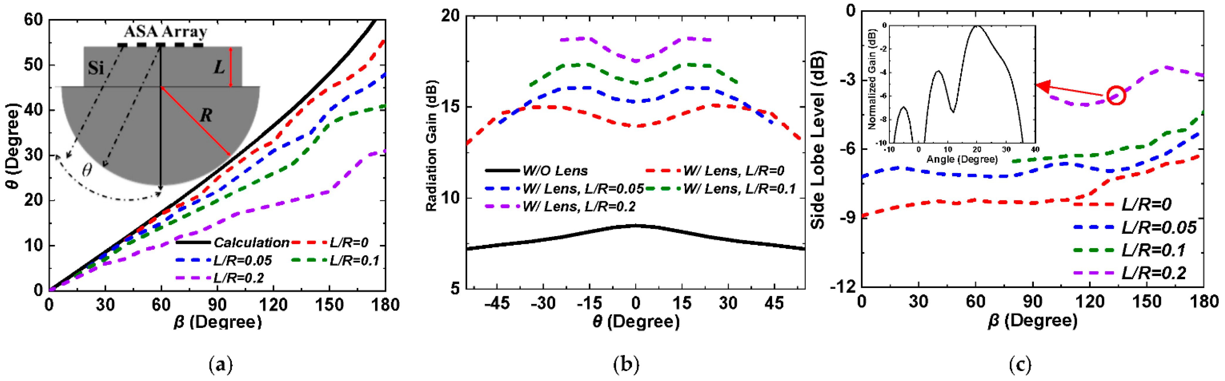
A relatively small overall array size is preferred for a chosen silicon lens of R = 5000 um to realize a high antenna gain improvement. Therefore, as a prototype demonstration, a small 1 × 3 array (the length of ~700 μm, see Figure 3a inset.) was first analyzed by full-wave simulation using ANSYS HFSS to study the feasibility and design strategies to adopt such lens-coupled configuration for beam-steering phased arrays. Figure 3a shows the simulated array scanning beam angle (i.e., θ) as a function of the feeding phase difference, β, for different L/R ratios (i.e., L changes from 0 μm to 1500 μm, with R fixed at 5000 μm). In general, θ increases when β raises from 0° to 180°, and smaller extension lengths result in larger beam steering angles for the same feeding phase difference. Specifically, the θ that can be achieved with a β of 180° changes from ~11° to ~20°, ~36° and 41° when L decreases from 1500 μm (L/R = 0.3) to 1000 μm (L/R = 0.2), 500 μm (L/R = 0.1), and 0 μm (L/R = 0), respectively. For all cases, especially for L/R = 0.2 and 0.3, further increase in β (e.g., β > 150°) does not lead to a significant increase in θ. Figure 3a also shows the theoretic calculation result for a phased array without silicon lens using the array factor technique (black curve) [18], and the beam steering angle increases almost linearly with increasing β (maximum θ = 63° when β = 180°). Compared to the lens-coupled ASA arrays studied above, ASA arrays without lenses generally show a larger achievable beam steering angle range. However, as shown later in this paper, lens-coupled array configurations could have much higher antenna gains which is much desired for mmW-THz applications.
Figure 3b shows the antenna gain as a function of θ for different configurations. For the lens-coupled ASA arrays, in general, the antenna gain increases with the increase in the extension length L. At the same time, the achievable beam scanning range (when β changes from 0° to ±180°) decreases. Particularly, the boresight gain (θ = 0°) increases from 12.91 dB to 16.41 dB, 19.02 dB, and 24.01 dB, while the extension length changes from 0 μm to 500 μm, 1000 μm, and 1500 μm, respectively. For most phased-array systems, the maximum gain is typically located at boresight, but for the lens-coupled arrays with L/R = 0 and L/R = 0.3 studied here, relatively lower gains at boresight as compared to other scanning angles can be observed. This is caused by the off-axis property of the extended hemispherical lens, i.e., a higher gain at other angles can be generated by the off-axis antenna elements, which causes a lower gain at boresight [19]. For a 1 × 3 ASA array without lens, as seen in Figure 3b, a peak gain of 7.2 dB is observed at θ = 0°, and the gain decreases when the antenna beam is steered away from the boresight (i.e., θ > 0° or θ < 0°). By using the lens-coupled array antenna configurations, a significant gain improvement can be achieved. Especially for the cases of L/R = 0.1 and 0.2, a decent gain improvement of 9.2 dB and 11.82 dB (compared to the same antenna array without the lens), respectively, have been achieved while maintaining a relatively large beam scanning range, i.e., ±36° and ±20°, respectively, demonstrating that the proposed lens-coupled phased-arrays are promising for 5G or beyond wireless communications and other more advanced THz applications.
In addition to the antenna gain, Figure 3c shows the antenna SLL as a function of β for different configurations. For L/R = 0, L/R = 0.1, and L/R = 0.2, SLL increases gradually with β when β increases from 0° to 120°. When β approaches 180°, the SLL increases rapidly due to the emerging grating lobes for a large θ, as suggested by ref. [14]. For the case of L/R = 0.3, the SLL becomes very high for all β (e.g., −2 dB when β = 150°, see the H-plane pattern in Figure 3c inset), since the large extension length of 1500 μm significantly bends the antenna rays and raise the antenna directivity for both the main beam and sidelobes. Therefore, a smaller extension length (e.g., L < 1500 μm) is preferred for designing a 1 × 3 lens-coupled ASA array to achieve a reasonably low SLL.
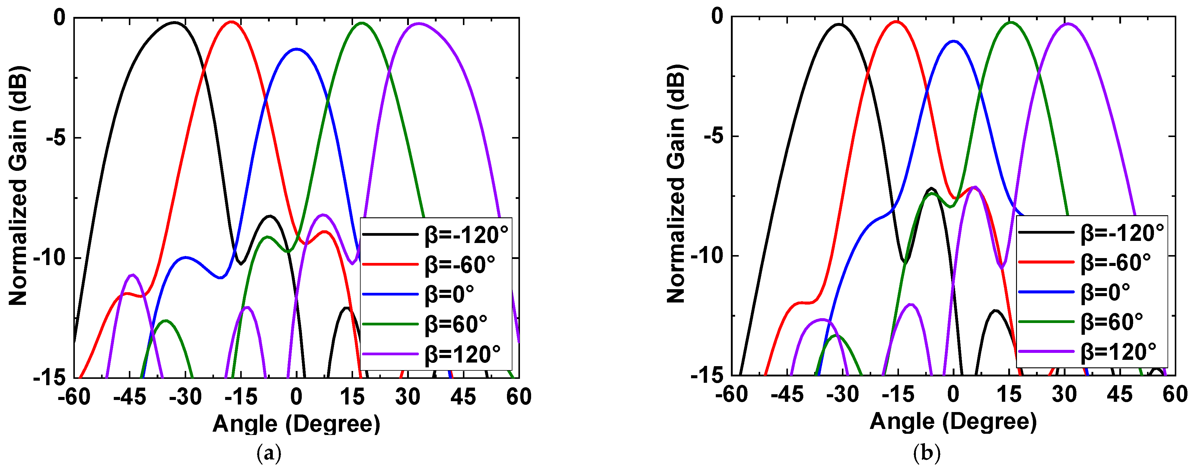
As discussed above, for a lens-coupled phased-array design, a larger extension length (for the same lens radius) typically leads to a higher gain improvement, but at the same time results in a narrower beam scanning range and higher SLL. As a compromise, for the configuration studied here, the extension lengths of 500 μm and 1000 μm with which both high antenna gains and low SLLs can be achieved are adopted for designing and demonstrating a lens-coupled 1 × 3 ASA array. For the two designs (L/R = 0.1 and L/R = 0.2), the simulated H-plane (i.e., the beam scanning plane) radiation patterns at different scanning angles (β = 0°, ±60°, and ±120°) are plotted in Figure 4. Figure 4a shows that for L/R = 0.1, the main beam of the 1 × 3 array scans from −22° to −11°, 0°, +11°, and +22°, as β changes from −120° to −60°, 0°, +60°, and +120°, respectively. The 3-dB beamwidth of the main beam for this design is estimated to be ~21°. For L/R = 0.2 (see Figure 4b), the main beam is steered in a smaller range, i.e., from −17° to −7°, 0°, +7°, and +17° when β changes from −120°, to −60°, 0°, +60°, and +120°, respectively. As expected, the 3-dB beamwidth reduces to ~15°. In summary, the designed lens-coupled 1 × 3 ASA phased array offers a high gain improvement while sacrificing the beam scanning range.
3.2. A 1 × 5 ASA Array Analysis
In order to achieve a wider beam scanning range, larger arrays with more antenna elements can be used. As a prototype demonstration, a 1 × 5 array is implemented (see Figure 5a inset) for full-wave simulation using ANSYS HFSS. The array size along the scanning plane (H-plane) is increased to ~1200 μm by adding two more antenna elements while keeping the same element spacing of 0.55λ. Figure 5a plots the scanning beam angle θ as a function of the feeding phase difference β. Similar to that observed in Figure 3a, θ increases as β increases, and smaller L leads to larger beam steering angles for the same β. The θ achieved when β = 180° is increased from 31° to 41°, 48°, and 56° while the L/R decreases from 0.2 to 0.1, 0.05 and 0, respectively. In addition, the theoretical calculation for a phased array without lens using the array factor technique is plotted (same as the one in Figure 3a). Finally, as compared to the lens-coupled 1 × 3 arrays, the lens-coupled 1 × 5 arrays show that improved beam scanning ranges, e.g., improvement of 15°, 5°, and 11° for L/R = 0, L/R = 0.1, and L/R = 0.2, respectively, have been achieved for β = 180°. This indicates that using a larger array size allows a larger beam scanning range for applications such as wireless communications, wireless power transmission systems, and radar systems [20].
Figure 5b plots the antenna gain as a function of θ for different 1 × 5 array configurations. Similar to the 1 × 3 arrays, the antenna gain of a 1 × 5 array increases when L increases. For example, the boresight gain raises from 13.92 dB to 15.27 dB, 16.63 dB, and 17.51 dB, while the L/R changes from 0, to 0.05, 0.1, and 0.2, respectively. Additionally, similar to the 1 × 3 configurations with L/R = 0 and L/R = 0.3, it is also observed that the peak gain achieved for a 1 × 5 array is not located at the boresight for all cases due to the more antenna elements at the off-axis positions. For a 1 × 5 array without lens, a maximum gain of 8.49 dB at boresight can be seen, and the gain gradually decreases to ~7.2 dB as the beam steers away from the boresight, i.e., from 0° to ±55° (see the black curve in Figure 5b). In addition, a good gain improvement can also be achieved by using lens-coupled configurations. For the cases of L/R = 0 and L/R = 0.05, a gain improvement of 6.51 dB and 7.51 dB (compared to the 1 × 5 array without the lens), and a beam scanning range of ±56° and ±48° (for β = ±180°), respectively, can be realized. Although the gain improvement and the peak gain of the 1 × 5 array are relatively smaller than those of the 1 × 3 array with L/R = 0.1 or L/R = 0.2, the beam scanning range has been enormously increased by ~40° when β = 180°, approaching the theoretical maximum of the ideal phased array (i.e., θ = ±63° when β = ±180°). This shows the great potential of the 1 × 5 arrays for future wireless communications.
The SLL was also characterized for the 1 × 5 arrays. Figure 5c shows the SLL as a function of β for different L/R ratios. For L/R = 0, L/R = 0.05 and L/R = 0.1, the SLL varies from −9 dB to −6 dB as β increases from 0° to 180°. As compared to that of a 1 × 3 array, the SLL of a 1 × 5 array is higher since the higher gain generated by off-axis antenna elements lead to a higher SLL even when β is small (e.g., 0° < β < 90°). For the case of L = 1000 μm (L/R = 0.2), the SSL is increased to about −4 dB (see the H-plane radiation pattern when β = 130° in Figure 5c inset), this means that an extension length of smaller than 1000 μm should be applied to a 1 × 5 array design for achieving a satisfactory SLL.
As described above, a 1 × 5 array can be utilized to obtain a wider beam scanning range. However, this leads to higher SLLs due to more antenna elements located at off-axis positions. In addition, since smaller extension lengths are used (to keep decent SLLs), relatively smaller gain improvement can be achieved. Therefore, to maintain a larger beam scanning range while achieving a high gain and low SLL, the extension lengths of 0 um (no extended part) and 250 μm are chosen for a prototype demonstration. Figure 6 shows the simulated H-plane radiation patterns of the 1 × 5 array at different scanning angles for the above two cases. For L/R = 0, the main beam angle can be steered from −31° to −15°, 0°, +15°, and +31°, as β changes from −120° to −60°, 0°, +60°, +120°, respectively, and the 3-dB beamwidth is ~20° (see Figure 6a). Figure 6b shows that for L/R = 0.05, the main beam steers from −26° to −14°, 0°, +14°, and +26° while β increases from −120° to −60°, 0°, +60°, +120°, respectively, and the 3-dB beamwidth of the main beam is decreased to ~18°, as expected. In summary, for the lens-coupled 1 × 5 array, a wider beam scanning range can be achieved as the gain improvement decreases, and SLL raises. By selecting a suitable extension length (e.g., L = 250 μm), the lens-coupled 1 × 5 array demonstrates a remarkable performance for potential near future 5G and beyond communications.
4. Conclusions
Table 1 shows the lens-coupled arrays comparison between different configurations with β from 0° to ±120° (for reasonably low SLL). For the same array element numbers (i.e., 1 × 3 array or 1 × 5 array), as the extension length increases, the gain improvement increases, and the beam scanning range decreases. In order to achieve a wider beam scanning range, a larger size array (e.g., 1 × 5 array) could be used with the same lens. However, the SLL of the 1 × 5 array is raised since the off-axis effect is more prominent. To solve the above issue, a shorter extension length is utilized to reduce gain improvement for low sidelobes and, hence, SLL. As a result, a 1 × 5 array with optimized extension length can achieve a wider beam scanning range while maintaining a reasonably low SLL. Although the reported approach is demonstrated using 200 GHz annular-slot antennas, the same approach using the lens-coupled configuration is universal and can be applied to other planar antenna topologies for phased arrays at different frequencies. The proposed lens-coupled phased array will soon be implemented with an optically controlled switch network [17] for a prototype demonstration of switchable THz beam steering.
This paper demonstrates the design, simulation, and analysis of a 200 GHz phased array, using lens-coupled annular-slot antennas. The simulation results show that for a 1 × 3 array, a ± 17° scanning angle, 11.82 dB gain improvement, and about −10 dB SLL can be achieved using an extended hemispherical silicon lens (R = 5000 μm, L = 500 μm). By applying a shorter extension length (i.e., L = 250 μm), a larger scanning angle of ±31°, 6.51 dB gain improvement, and a sidelobe level of about −8 dB can be realized by using a 1 × 5 array. On the basis of the high performance reported here, we believe that the lens-coupled phased arrays have great potential and may find promising applications for future 5G and beyond wireless communications.
Author Contributions
Conceptualization, P.L. and L.L.; Data curation, P.L.; Formal analysis, P.L. and L.L.; Funding acquisition, L.L.; Investigation, P.L.; Methodology, P.L. and L.L.; Project administration, L.L.; Software, P.L. and Y.S.; Supervision, L.L.; Writing—original draft, P.L.; Writing—review and editing, P.L., Y.S., Y.D. and L.L. All authors have read and agreed to the published version of the manuscript.
Funding
This work was supported in part by the National Science Foundation under Grants ECCS-1711631 and ECCS-1711052.
Institutional Review Board Statement
Not applicable.
Informed Consent Statement
Not applicable.
Data Availability Statement
The data that support the findings of this study are available from the corresponding author upon reasonable request.
Conflicts of Interest
The authors declare no conflict of interest.
References
- Singh, R.; Sicker, D. Beyond 5G: THz spectrum futures and implications for wireless communication. In Proceedings of the 30th European Regional International Telecommunications Society (ITS) Conference, Helsinki, Finland, 16–19 June 2019. [Google Scholar]
- Rappaport, T.S.; Xing, Y.; Kanhere, O.; Ju, S.; Madanayake, A.; Mandal, S.; Alkhateeb, A.; Trichopoulos, G.C. Wireless communications and applications above 100 GHz: Opportunities and challenges for 6G and beyond. IEEE Access 2019, 7, 78729–78757. [Google Scholar] [CrossRef]
- Gu, X.; Liu, D.; Sadhu, B. Packaging and antenna tntegration for silicon-based millimeter-wave phased arrays: 5G and beyond. IEEE J. Microw. 2021, 1, 123–134. [Google Scholar] [CrossRef]
- Zhang, J.; Kang, K.; Huang, Y.; Shafi, M.; Molisch, A.F. Millimeter and THz wave for 5G and beyond. China Commun. 2019, 16, 3–6. [Google Scholar]
- Natarajan, A.; Komijani, A.; Guan, X.; Babakhani, A.; Hajimiri, A. A 77-GHz phased-array transceiver with on-chip antennas in silicon: Transmitter and local LO-path phase shifting. IEEE Trans Microw. Theory Tech. 2006, 41, 2807–2819. [Google Scholar] [CrossRef] [Green Version]
- Valdes-Garcia, A.; Nicolson, S.T.; Lai, J.-W.; Natarajan, A.; Chen, P.-Y.; Reynold, S.K.; Zhan, J.-H.; Kam, D.; Liu, D.; Floyd, B. A fully integrated 16-element phased-array transmitter in SiGe BiCMOS for 60-GHz communications. IEEE J. Solid-State Circuits. 2010, 45, 2757–2773. [Google Scholar] [CrossRef]
- Sadhu, B.; Tousi, Y.; Hallin, J.; Sahl, S.; Reynolds, S.K.; Renstrom, O.; Sjogren, K.; Haapalahti, O.; Mazor, N.; Bokinge, B.; et al. A 28-GHz 32-element TRX phased-array IC with concurrent dual-polarized operation and orthogonal phase and gain control for 5G communications. IEEE J. Solid-State Circuits. 2017, 52, 3373–3391. [Google Scholar] [CrossRef]
- Schneider, T.; Wiatrek, A.; Preussler, S.; Grigat, M.; Braun, R.P. Link budget analysis for terahertz fixed wireless links. IEEE Trans. THz Sci. Technol. 2012, 2, 250–256. [Google Scholar] [CrossRef]
- Grzyb, J.; Andree, M.; Jain, R.; Heinemann, B.; Pfeiffer, U.R. A lens-coupled on-chip antenna for dual-polarization SiGe HBT THz direct detector. IEEE Antennas Wirel. Propag. Lett. 2019, 18, 2404–2408. [Google Scholar] [CrossRef]
- Rutledge, D.; Muha, M. Imaging antenna arrays. IEEE Trans. Antennas Propag. 1982, 30, 535–540. [Google Scholar] [CrossRef]
- Han, R.; Afshari, E. A CMOS high-power broadband 260-GHz radiator array for spectroscopy. IEEE J. Solid-State Circuits. 2013, 48, 3090–3104. [Google Scholar] [CrossRef]
- Tong, C.; Blundell, R. An annular slot antenna on a dielectric half-space. IEEE Trans. Antennas Propag. 1994, 42, 967–974. [Google Scholar] [CrossRef]
- Liu, L.; Xu, H.; Lichtenberger, A.W.; Weikle, R.M. Integrated 585-GHz hot-electron mixer focal-plane arrays based on annular slot antennas for imaging applications. IEEE Trans Microw. Theory Tech. 2010, 58, 1943–1951. [Google Scholar] [CrossRef]
- Bray, M.G.; Werner, D.H.; Boeringer, D.W.; Machuga, D.W. Optimization of thinned aperiodic linear phased arrays using genetic algorithms to reduce grating lobes during scanning. IEEE Trans. Antennas Propag. 2002, 50, 1732–1742. [Google Scholar] [CrossRef]
- Filipovic, D.; Gearhart, S.; Rebeiz, G. Double-slot antennas on extended hemispherical and elliptical silicon dielectric lenses. IEEE Trans Microw. Theory Tech. 1993, 41, 1738–1749. [Google Scholar] [CrossRef]
- Jiang, Z.; Rahman, S.M.; Hesler, J.L.; Fay, P.; Liu, L. Design and characterisation of a 200 GHz tunable lens-coupled annular-slot antenna with a 50 GHz tuning range. IET Proc. Microw. Antennas Propag. 2014, 8, 842–848. [Google Scholar] [CrossRef]
- Li, P.; Shi, Y.; Deng, Y.; Liu, L. A 200 GHz switchable beam-steering phased array using lens-coupled annular-slot antennas. In Proceedings of the 46th International Conference on Infrared, Millimeter and Terahertz Waves (IRMMW-THz), Chengdu, China, 29 August–3 September 2021. [Google Scholar]
- Balanis, C.A. Antenna Theory: Analysis and Design, 3rd ed.; Wiley: Hoboken, NJ, USA, 2005; pp. 799–801. [Google Scholar]
- Filipovic, D.F.; Gauthier, G.P.; Raman, S.; Rebeiz, G.M. Off-axis properties of silicon and quartz dielectric lens antennas. IEEE Trans. Antennas Propag. 1997, 45, 760–766. [Google Scholar] [CrossRef]
- Ahn, B.; Hwang, I.J.; Kim, K.S.; Chae, S.C.; Yu, J.W.; Lee, H.L. Wide-angle scanning phased array antenna using high gain pattern reconfigurable antenna elements. Sci. Rep. 2019, 9, 18391. [Google Scholar] [CrossRef]
Figure 1.
(a) The configuration of the designed 200 GHz beam-steering phased array using five lens-coupled annular-slot antennas (the feeding points are shown as red squares), and (b) the sideview of the lens-coupled phased array (a 1 × 5 array is depicted as the illustrative purpose).
Figure 1.
(a) The configuration of the designed 200 GHz beam-steering phased array using five lens-coupled annular-slot antennas (the feeding points are shown as red squares), and (b) the sideview of the lens-coupled phased array (a 1 × 5 array is depicted as the illustrative purpose).

Figure 2.
(a) The configuration of the designed 200 GHz single ASA (the metal part is shown as gray) and (b) its radiation patterns into the dielectric half-space.
Figure 2.
(a) The configuration of the designed 200 GHz single ASA (the metal part is shown as gray) and (b) its radiation patterns into the dielectric half-space.

Figure 3.
(a) The feeding phase difference β versus scanning beam angle θ (the 1 × 3 array configuation is shown as inset), (b) the radiation gain versus scanning beam angle θ and (c) the sidelobe level versus phase difference θ at different extension lengthes L for a 1 × 3 array (the H-plane radiation pattern for an L/R = 0. 3 at β of 150° is shown as inset).

Figure 4.
The radiation pattern of the H-plane for a 1 × 3 array with (a) L/R = 0.1 and (b) L/R = 0.2 at different phase differences β.
Figure 4.
The radiation pattern of the H-plane for a 1 × 3 array with (a) L/R = 0.1 and (b) L/R = 0.2 at different phase differences β.

Figure 5.
(a) The feeding phase difference β versus scanning beam angle θ (the 1 × 5 array configuation is shown as inset), (b) the radiation gain versus scanning beam angle θ and (c) the sidelobe level versus phase difference θ at different extension lengthes L for a 1 × 5 array (the H-plane radiation pattern for an L/R = 0.2 at β of 130° is shown as inset).

Figure 6.
The radiation pattern of the H-plane for a 1 × 5 array with (a) L/R = 0 and (b) L/R = 0.05 at different phase differences β.
Figure 6.
The radiation pattern of the H-plane for a 1 × 5 array with (a) L/R = 0 and (b) L/R = 0.05 at different phase differences β.


Table 1.
The lens-coupled arrays comparison between different configurations (β from 0° to ±120°).
| 1 × 3 Arrays w/L/R = 0.1 | 1 × 3 Arrays w/L/R = 0.2 | 1 × 5 Arrays w/L/R = 0 | 1 × 5 Arrays w/L/R = 0.05 | |
|---|---|---|---|---|
| Boresight gain | 16.41 dB | 19.02 dB | 13.92 dB | 15.27 dB |
| Gain imrovement | 9.2 dB | 11.82 dB | 6.51 dB | 7.51 dB |
| Beam scanning | 44° | 34° | 62° | 52° |
| SLL | −12 dB to −9 dB | −12 dB to −9 dB | −9 dB to −7 dB | −9 dB to −7 dB |
Publisher’s Note: MDPI stays neutral with regard to jurisdictional claims in published maps and institutional affiliations. |
© 2022 by the authors. Licensee MDPI, Basel, Switzerland. This article is an open access article distributed under the terms and conditions of the Creative Commons Attribution (CC BY) license (https://creativecommons.org/licenses/by/4.0/).
Share and Cite
MDPI and ACS Style
Li, P.; Shi, Y.; Deng, Y.; Liu, L. Computational Analysis of a 200 GHz Phased Array Using Lens-Coupled Annular-Slot Antennas. Appl. Sci. 2022, 12, 1407. https://0-doi-org.brum.beds.ac.uk/10.3390/app12031407
AMA Style
Li P, Shi Y, Deng Y, Liu L. Computational Analysis of a 200 GHz Phased Array Using Lens-Coupled Annular-Slot Antennas. Applied Sciences. 2022; 12(3):1407. https://0-doi-org.brum.beds.ac.uk/10.3390/app12031407
Chicago/Turabian StyleLi, Peizhao, Yu Shi, Yijing Deng, and Lei Liu. 2022. "Computational Analysis of a 200 GHz Phased Array Using Lens-Coupled Annular-Slot Antennas" Applied Sciences 12, no. 3: 1407. https://0-doi-org.brum.beds.ac.uk/10.3390/app12031407
Note that from the first issue of 2016, this journal uses article numbers instead of page numbers. See further details here.