Article

Robust Piezoelectric Coefficient Recovery by Nano-Inclusions Dispersion in Un-Poled PVDF–Ni0.5Zn0.5Fe2O4 Ultra-Thin Films

1
LSPM CNRS UPR-3407, University of Sorbonne Paris North (USPN), 99, Av. J. B. Clément, 93430 Villetaneuse, France
2
Institute of Materials Science, Vietnam Academy of Science and Technology, 18 Hoang Quoc Viet Str., Cau Giay Dist., Hanoi 10072, Vietnam
3
LPL CNRS UMR-7538, University of Sorbonne Paris North (USPN), 99, Av. J. B. Clément, 93430 Villetaneuse, France
4
ICMAB CSIC, Autonomous University of Barcelona (UAB), 08193 Bellaterra, Spain
5
GREMAN UMR7347—CNRS, Tours University (UT), Parc Grandmont, 37200 Tours, France
*
Authors to whom correspondence should be addressed.
Submission received: 5 December 2021 / Revised: 26 January 2022 / Accepted: 28 January 2022 / Published: 2 February 2022
(This article belongs to the Special Issue Recent Advances in Application of Coatings and Films)

Abstract

:

Featured Application

Shapeable piezo-magnetic sensors.

Abstract

This work aimed to study the influence of the hybrid interface in polyvinylidene fluoride (PVDF)-based composite thin films on the local piezoelectric response. Our results provide evidence of a surprising contradiction: the optimization process of the β-phase content using nano-inclusions did not correspond to the expected nanoscale piezoelectric optimization. A large piezoelectric loss was observed at the nanoscale level, which contrasts with the macroscopic polarization measurement observations. Our main goal was to show that the dispersion of metallic ferromagnetic nano-inclusions inside the PVDF films allows for the partial recovery of the local piezoelectric properties. From a dielectric point of view, it is not trivial to expect that keeping the same amount of the metallic volume inside the dielectric PVDF matrix would bring a better piezoelectric response by simply dispersing this phase. On the local resonance measured by PFM, this should be the worst due to the homogeneous distribution of the nano-inclusions. Both neat PVDF films and hybrid ones (0.5% in wt of nanoparticles included into the polymer matrix) showed, as-deposited (un-poled), a similar β-phase content. Although the piezoelectric coefficient in the case of the hybrid films was one order of magnitude lower than that for the neat PVDF films, the robustness of the polarized areas was reported 24 h after the polarization process and after several images scanning. We thus succeeded in demonstrating that un-poled polymer thin films can show the same piezoelectric coefficient as the poled one (i.e., 10 pm/V). In addition, low electric field switching (50 MV/m) was used here compared to the typical values reported in the literature (100–150 MV/m).

1. Introduction

Hybrid films based on electroactive polymer with improved dielectric properties have drawn tremendous interest due to the fact of their diverse applications in the development of film based sensors and actuators [1,2,3]. Their flexible, printable and stretchable properties are the building blocks for the next generation of a smart nanotechnology [4,5,6,7]. The latter includes devices that mimic nature’s multifunctionalities and appearance. Recently, magnetic hybrid devices reproducing the ability of some organisms to detect and respond to a small magnetic field (i.e., orientate themselves with respect to the Earth’s magnetic field for navigation purposes) have been realized and reported in parallel to the successful elaboration of multifunctional foils that mimic imperceptible magnetic skin. This may help human skin to experience unfamiliar senses [5,7]. As a matter of fact, the development of nanocomposites will benefit a variety of wearable electronics that have functionalities from healthcare monitoring and functional medical implants up to the recovery of mechanical movements and the early diagnose of heart dysfunctions (see [4] and the references therein). In order to achieve large-scale use of these smart devices aimed at revolutionizing common electronics, it is necessary to perfectly control the artificial combination of a flexible electroactive polymer phase with a magnetostrictive nanometric one. Coupling together two phases presenting two different chemical natures (i.e., organic and inorganic) and physical properties (i.e., piezoelectric and magnetostrictive) opens the way to either modulating a dielectric polarization with an external magnetic field or inducing magnetization by an applied electric field [8,9,10,11] through the medium of the strain. With this type of strain-mediated magnetoelectric (ME) nanomaterials, the dimensional change of one phase has to be efficiently transmitted to the other in order to present a strong ME coupling coefficient at room temperature and to be suitable for practical applications. Therefore, the phase connectivity at the interphase of the two phases has to be robust, and the electrostrictive and magnetostrictive properties of each phase should be optimized as well. Among polymers, poly (vinylidene fluoride) (PVDF)-based polymers and co-polymers have demonstrated high piezoelectric and electrostrictive qualities due to the fact of their semi-crystalline nature coming from the crystallization of the polar β-phase [12,13,14,15]. Thanks to the maximization of the latter at the expense of the other PVDF non-polar phases, laminated hybrid geometry (2–2 composites)-based PVDF–TrFE/Metglas have shown a high ME coupling coefficient of 320 V cm−1 Oe−1. At the same time, this 2–2 configuration has provided evidence of the weakness of the connectivity between the two phases due to the need for a binder (usually epoxy) that is relatively brittle together with a nonlinear ME response at low magnetic field [16,17]. These characteristics make them non-adaptable to future applications. These results have opened the way for an increasing number of works focusing on 0–3 particulate nanocomposites that allow for exploiting the possibility of dispersing high magnetostrictive nanoparticles within a piezoelectric PVDF matrix. This 0–3 configuration retains good flexibility for the nanocomposite together with a well-controlled connectivity [18,19,20,21,22]. Mostly, the groups of Lanceros-Mendez and Martins have made large efforts and published a great number of works on the development and optimization of PVDF and co-polymers based on 0–3 composites using ferrite magnetic nanoparticles [18,19,20,21,22,23,24,25,26,27,28,29]. The latter are the preferred candidate for ME nanocomposites, as they show high magnetostrictive coefficient λs at room temperature as well as stable magnetic properties due to the fact of their high Curie temperature [23]. Both λ and TC are strongly dependent on the crystal and size properties of the ferrite nanoparticles as well as on the substitution of the divalent ion (Co, Ni, Mn) [24,25], thus allowing for tight control of the magnetostrictive properties. Unfortunately, they have shown that in order to maximize the ME coupling coefficient in these nanocomposites, a high loading of nanoparticles has to be used (over 40 wt%), which inevitably sacrifices the flexibility of the composite material, introduces a high porosity of the hybrid nanostructure, and also compromises the dielectric and piezoelectric properties of the polymer due to the metallic properties of the magnetic nanoparticles. As a matter of fact, an increase in the conductivity of the composite is observed with an increase of the number of nanoparticles agglomerates at the expense of the piezoelectric properties of the hybrid material. A recent article [30] showed that the dispersion of ultra-small CoFe2O4 nanoparticles (i.e., smaller than 7 nm) using a 1H, 1H, 2H, and 2H-perfluorooctyltriethoxysilane (POTS) functionalization, not only ensured the flexibility of ME nanocomposites but also enhanced the interplay between the magnetostrictive phase and the piezoelectric one by allowing for the optimization of an ME coupling coefficient of 34 mV cm−1 Oe−1 using a low content of magnetic nanoparticles (i.e., 20 wt%). The authors report that POTS’ long fluoric chains together with the small size of the nanoparticles (matching the size of PVDF–TrFE crystals) are beneficial for the polar phase crystallization of the polymer and also for the robustness of the 0–3 connectivity among the two phases and, thus, the strain transfer at their interphase. The dielectric measurements showed a stable dielectric constant at low frequency (between 100 Hz and 10 KHz) with low dielectric loss accompanied by optimized ferroelectric polarization cycles. This study confirmed previously published magneto-capacitive measurements reported for Fe3O4–PVDF composite films [31], showing the importance of the electrical-insulated coating of Fe3O4 nanoparticles obtained using a very thin silica layer. The dielectric properties were again clearly optimized in this case thanks to the control of the current density leakage. The presence of insulated coated metallic nanoparticles enabled the stabilization of the dielectric loss. This was recently confirmed also in the case of a lower loading of the metallic nano-inclusions inside the polymer film [32]. The authors showed the possibility of optimizing the dielectric properties by using an ultra-small load of well-dispersed nanoparticles (i.e., <1% in volume). Despite these efforts, it is important to underline that all these results were obtained on mainly thick micrometer films (i.e., 30–40 μm), annealed for 1 or a few hours at high temperature (>100 °C) and often poled during the elaboration process at high electric field in order to maximize the crystalline β-phase content. These treatments are well known not to be compatible with the integration of these hybrid films into standard technology processes. In addition, although there have been a considerable number of works measuring their dielectric, piezoelectric, and magnetoelectric properties that undeniably support the idea of their optimization being directly linked to the dispersion of the magnetic nano-inclusions, currently, there is still an important lack of the characterization of the local electroactive and magnetostrictive properties. Several studies have shown the local piezoelectric properties of PVDF–TrFE copolymer neat films [33] as well as hybrid films based on the artificial mixing of the PVDF and copolymer phase with non-magnetic nano-phases (e.g., CNTs, ZnO, (Pb,Ba)(Zr,Ti)O3, graphene) [34,35,36,37,38,39]. Only very recent studies [40,41] have shown the possibility of using the magnetic phase organization inside the polymer matrix to improve the local PFM properties under the application of a magnetic field. Currently, these local PFM results have not provided the opportunity to understand the connection between the optimization of the macroscopic dielectric properties and the local electroactive one, both in the case of low loading and for the dispersion of the magnetic nanoparticles. In this work, we aimed to show that the optimization of the β-phase content in hybrid thin films surprisingly does not correspond to an increase in the local piezoelectric behavior of the PVDF. Rather, it causes a huge piezoelectric coefficient loss. We also show that the dispersion of the metallic ferromagnetic nano-inclusions inside the PVDF allowed for the partial recovery of the piezoelectric properties. In order to foresee the practical applications, we show our results on as-grown and un-poled 0–3 nanocomposite ultra-thin films (thickness < 100 nm), displaying the robustness of the local polarization as a function of time. With this aim, we compared the piezoelectric response of hybrid films with functionalized and non-functionalized nanoparticles to that of neat PVDF films presenting similar β-phase content. Keeping in mind the needs of microelectronic applications, we focused our studies on very thin (mean thickness of approximately 100 nm) and smooth PVDF and hybrid PVDF films (mean roughness of approximately 10 nm), containing the smallest possible percentage of inorganic nanoparticles (0.5 wt%) in order to keep the flexible characteristics of the polymer and to at the same time optimize the electroactive phase content. Although more studies should be undertaken to determine the right balance between the optimization of the ME coupling and the dispersion of the magnetic nano-inclusions as well as of the easy elaboration of these hybrid nanostructures, our results show the potentiality of this 0 nano-composites for the next generation of multifunctional devices.

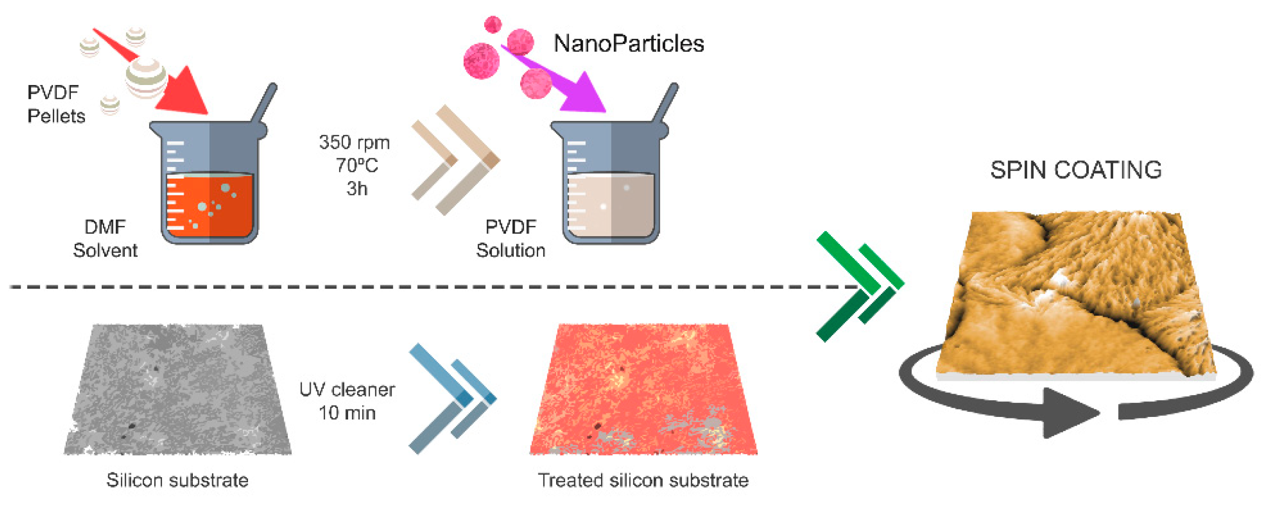
2. Materials and Methods

All the chemicals used in this work were of analytical grade and used as purchased from Sigma–Aldrich. Poly (vinylidene fluoride) with a molecular weight of 180,000 phosphonic acid molecules was used for the grafting, and a N,N-dimethyl formamide (DMF) solution, acetone, isopropanol, tetrahydrofurane (THF) solution was thus used for the fabrication of the polymer-based films. The silicon substrates were pretreated before the film deposition in order to remove all contaminants using a standard clean room procedure. All details for the thin films’ elaboration can be found in our previous work [42] and are summarized briefly in Figure 1.
All the films presented in this work were deposited by a standard spin coating technique on conductive substrates in order to properly perform the local piezoelectric characterization. In the case of neat PVDF film, a specific number of PVDF pellets (MPVDF = 180,000), Mw PVDF = 180,000 g·mol−1, were completely dissolved in DMF for 3 h at 70 °C before adding acetone. This PVDF solution was then drop casted onto the pretreated substrate and put in rotation at various speeds to allow for the spreading of the solution [42]. Very flat neat PVDF films with a mean roughness between 3 and 14 nm and homogeneous microstructures were obtained after the optimization of the spin coating process and parameters (see Supplementary Materials Figures S1 and S2, Table S1). In the case of the hybrid films, we decided to use a low concentration of pellets (2% weight of PVDF) in order to elaborate very thin films with a similar approach used for the neat PVDF ones. To control the dispersion of the nano-inclusions inside the PVDF matrix as well as the connectivity between the two phases, we used 2 categories of nanoparticles: functionalized and non-functionalized one [42]. The Ni0.5Zn0.5Fe2O4 nanoparticles (NZFO-NPs) used to elaborate our hybrid thin films were synthesized using a soft chemistry polyol route in 1,2-propandiol as reported elsewhere [43,44,45]. In order to avoid their agglomeration as much as possible and to promote their dispersion in the hydrophobic matrix, we functionalized them with specific molecules. The procedure for the functionalization of the nanoparticles was conducted on the basis of a previously reported process [46,47]. Again, very flat films were obtained with a mean roughness of 5 nm and homogeneous microstructures (see Supplementary Materials Figures S1 and S2, Table S1). All the films studied in this work presented a mean thickness between 75 and 100 nm, and they were not poled during the elaboration process. In the case of the hybrid films, the nanoparticles content was kept at 0.5% wt for both the functionalized and non-functionalized cases (see Supplementary Materials Table S1). More details on the optimization of the films can be found in [42]. The X-ray diffraction patterns acquired from the four samples studied are reported in Figure S3 in the Supplementary Materials. The main Bragg peaks of the PVDF crystalline phases were evidenced and clearly showed the presence of several phases (α, β, and γ). The diffraction lines associated with the nanoparticles’ crystalline peaks are not reported here, as they have already been analyzed in Reference [42] for both F-PVDF and NF-PVDF thin films. The spherical morphology, mean size, and magnetization behavior of the nanoparticles are reported in Figure S4a–c of the Supplementary Materials. Infrared (IR) spectroscopy (Thermo Nicolet, AVATAR 370 FTIR) was carried out over a range of 700–1500 cm−1 and used to quantify the electroactive phase content of PVDF. The surface structures and film roughness were analyzed by statistical studies of high-resolution AFM images (AFM, Brucker D3100). The microstructure of the NZFO/PVDF 0–3 nanocomposites was studied by scanning electron microscope (SEM, QUANTA FEI 200, FEG-ESEM) in the low-vacuum mode (LV-water vapor injection) using an acceleration voltage of 10–15 kV and under a pressure of 50–60 Pa. The samples were analyzed both in an in plane and cross-sectional configuration. The out-of-plane piezoelectric response was measured using an Agilent 5500 SPM with the AC Mode III accessory. The out of the resonance frequency for the PFM measurements under AC voltage applied, was set at 20 kHz in order to avoid possible artifacts related to the contact frequency resonance of the tip. All the images and the piezoelectric measurements were acquired in low ambient humidity conditions of less than 10%. Measurements were performed using Pt-coated Si tips (RMN, spring constant k ≈ 0.08 N/m). Images were acquired using a modulation voltage of 5 Vp.p.. The polarization process of opposite squared area was conducted, respectively, with positive and negative 5 V applied. Thus, the maximum electric field applied for the neat PVDF films was 50 MV/m and 66 MV/m for the functionalized hybrid ones. Piezoelectric coefficients (d33) were obtained by varying the applied voltage up to a maximum of 10 V (i.e., by applying a maximum field of 100 MV/m for the thickest film and 133 MV/m for the thinnest one).

3. Phase Content and Dispersion of Nano-Inclusions

PVDF films (neat and hybrid ones) were deposited on conductive substrates using the natural stretching mechanism applied by the spin coating technique, and we adjusted the elaboration parameters (i.e., speed, steps, density of the PVDF-based solution, and temperature) in order to optimize the β-phase content [42]. We present here four different samples: two neat PVDF films (hereafter referred to as PVDF-20 and PVDF-80) with similar thicknesses obtained by the same spin coating process using two different elaboration temperatures (see Supplementary Materials Table S1). The structural and electroactive properties of these two samples were compared to those of PVDF hybrid films with 0.5% wt of non-functionalized nanoparticles (hereafter referred to as NF-PVDF) and to a PVDF hybrid one with 0.5% wt of functionalized nanoparticles (hereafter referred to as F-PVDF). Details on the elaboration and XRD diffraction patterns of the four samples can be found in [42]. The surface microstructure comparison of the four films obtained by SEM and AFM analysis is shown in the Supplementary Materials Figures S1 and S2. The results show a homogeneous morphology of the large surfaces observed by SEM technique and confirmed by local surface AFM measurements. The characteristic micrometric spherulitic structures were visible with additional sub-micron fiber structures in agreement with the previously reported morphology of PVDF films presenting a majority of the β-phase content [48,49]. The whole set of films presented a mean thickness in the range of 75–100 nm and a mean roughness in the range of 3–14 nm. To study the effect of the nanoparticle interface organization on the PVDF β-phase nucleation, FTIR was used, as this method is proven to be as suitable as X-ray diffraction for the determination of the different phases of PVDF. As already reported [42], for the very thin PVDF films, the diffracted intensity was too low. This makes it useful for qualitative identification of the corresponding phase (see Supplementary Materials Figure S3), but it hinders quantitative studies. On the contrary, specific bands of FTIR transmittance in a wavelength range between 500 and 1500 cm−1 have previously been identified to be clearly characteristic of the different phases’ content [13,14] and demonstrated to be able to quantify the electroactive phase content in PVDF materials. We thus recorded the FTIR spectra of the four films at room temperature in the 600−1500 cm−1 wavenumber range. A baseline recorded at room temperature was subtracted from the corresponding spectrum using the spectrometer software. We also took into account the Si substrate’s transmittance in order to avoid any dependencies of our analysis on the substrate. In Figure 2, we report FTIR normalized spectra presenting the characteristic bands of the α and β phases for the four films.
Several bands located at 840, 870, 1275, 1340, and 1403 cm−1 were clearly identified and characterized the β phase (see Figure 2) [13,14,48]. These bands were related to the sequences of more than three and/or four trans-conformations [13,14] of the polar phases. In Figure 2, the characteristic absorption peak at 840 cm−1 was used to quantify the β-phase content, showing similar absorbance characteristics among the four samples. Non-polar α-phase absorptions were still visible, even though they were less intense, at 766, 795, and 1211 cm−1. The FTIR spectra also showed the presence of several absorption bands at 1070 and 1175 cm−1. These latter bands were characteristic of the vibrations of the carbon–carbon skeleton in the polymer [13,14,48]. Again, the intensities of these bands seemed not to evolve as a function of the thermal treatment and the presence of the nanoparticles, emphasizing a good organization of the polymer structure for all our samples. The quantification of the γ phase was more difficult, as exclusive FTIR bands corresponding to the γ phase appeared as shoulders (see Figure 2). Gregorio et al. [14,49] analyzed FTIR absorptions by assuming the Lambert–Beer law and calculated the absorption coefficients, Kα and Kβ, at the respective wave numbers of 766 and 840 cm−1. In this manner, according to [14,49], the relative fraction of the β-phase content in a sample containing mainly α and β phases is:
F ( β ) = A β ( K β / K α ) A α + A β = A β 1.26 A α + A β
where F(β) represents the β-phase content; Kα and Kβ are the absorption coefficients with respective values of 6.1 × 10⁴ and 7.7 × 104 cm2mol−1; Aα and Aβ are the absorbances at 766 and 840 cm−1 calculated using the incident and transmitted intensities of the IR waves.
A n = log I n 0 I n = α , β
This expression has been widely used in the literature [13,14,18,19,20,21,22,48], and in our case, it gives the following values for the β-phase content in the four samples (see Figure 3):
IR observations support the conclusion that both neat PVDF films and hybrid ones presented a similar content of electroactive phase with a slight increase (as expected) in the presence of the nano-inclusions. As reported before [42], we decided to use as nano-fillers the isotropic nanoparticles of Ni0.5Zn0.5Fe2O4 (NZFO-NPs). Previous work has already demonstrated that the interaction between the negatively charged surface of the NZFO-NPs and the positively charged polymer CH2 groups promotes nucleation of the β phase in PVDF [19]. Remarkably, when hydrophilic molecules functionalize the surface of the nano-fillers, a uniform dispersion of the nano-fillers is obtained. These hydrophilic parts interact with the C–F polar bonds in the PVDF matrix through hydrogen bonding, and all dipoles along the molecular chains of the polymer can align. Consequently, the β-phase content is enhanced [30,31] as well as the polymer structure. In order not to destroy the flexible properties of the PVDF, we worked at a very low loading mass percentage (<1% wt) [42] with very small nanoparticles of average diameter of 3.5 nm (see Figure 4a–c in the Supplementary Materials for more details on the nanoparticles’ morphological and magnetic characterizations). It is worth noticing here that ferromagnetic nanoparticles behave like strong nano-magnets; thus, as soon as they are sufficiently nearby (closer than 10 nm) they attract each other. Once they agglomerate, it is very difficult to disperse them. The four samples were studied using SEM images of both backscattered and secondary electrons, BSEs and SEs, respectively. Figure 4a presents the SEM image obtained for the neat PVDF film (PVDF-20) in which no contrast can be seen for both the BSE and SE images. In Figure 4b,c, we compare non-functionalized NPs embedded in the PVDF film (NF-PVDF) with their functionalized NPs (F-PVDF) counterparts. The BSE images provide a clean view of the dispersion of the nanoparticles, as they are related to the Z number of the material imaged. We found that functionalization was a key parameter for dispersing the magnetic nanoparticles in the film. The cross-section of the film shown in Figure 4d shows that the NPs were homogeneously dispersed through the thickness of film and not just dispersed on its surface and forming aggregates in depth. A statistical analysis of the distribution of the NPs was conducted using the ImageJ program and provides evidence for the homogeneous distribution of NP agglomerates with their surface size reduced by one order of magnitude between the NF-PVDF and F-PVDF samples (see Supplementary Materials Figure S5).

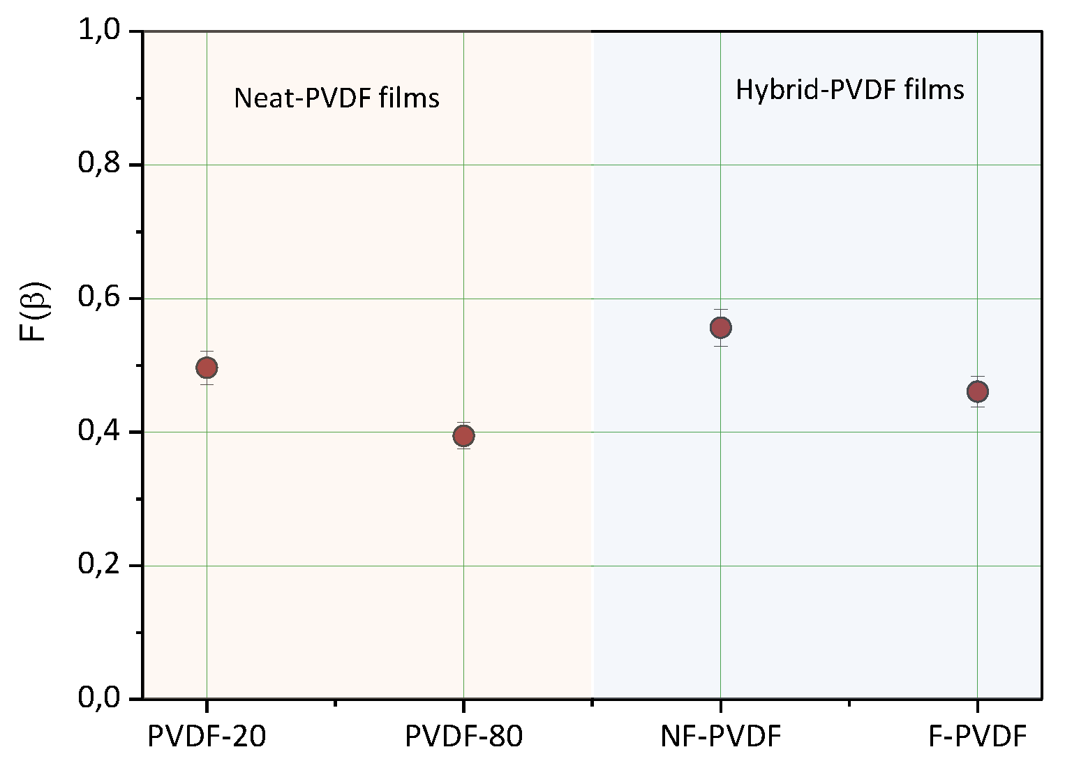
4. Recoveries and Robustness of Local Piezoelectric Properties

Comparison between the functionalized and non-functionalized hybrid films allowed us to study the effect of the dispersion of the nanoparticles inside the matrix, not only over the optimization of the interface between the two phases but also over the local piezoelectric properties of the polymer. As we reported before, to efficiently stress the magnetostrictive phase of the NPs, thus controlling their moment orientation by applying an electric field on the piezoelectric polymer, is a major key parameter for using these hybrid thin films in new magnetic sensors. In this frame, the study of the local piezoelectric response of the polymer by piezoelectric force microscopy is of primary importance. In Figure 5, we show the piezoelectric response, which was measured by applying an alternative electric bias field through the use of a nanometric-probing tip. The latter is in contact with the surface of the polymer and applies the field through the thickness of the film (i.e., the conductive substrate was maintained at 0 V). This electric bias resulted in sample deformation due to the converse piezoelectric effect. Piezoelectric surface displacement was detected by the reflection of a laser beam on the photodiode of the microscope that records the cantilever vibration/position. The out-of-plane piezoelectric response was thus measured when an AC voltage was applied through the tip with an amplitude vibration in the range of 0–10 V. The voltage was increased by a step of 2 V as can be seen in Figure 5a.
Measurement of the tip vibration is given as a function of the tip frequency in Figure 5a. The scan rate was 0.5 Hz, and the scan area was 1 × 1 μm2. Figure 5a shows the out-of-plane piezoelectric response for the whole set of samples. These results confirm a linear piezoelectric effect in the neat PVDF films as well as in the hybrid ones. This is in agreement with the presence of a polar phase in all our samples. However, in the case of hybrid-PVDF films (i.e., NF-PVDF and F-PVDF), the vibration amplitude was very small, showing a large loss of the piezoelectric response compared to the neat PVDF films. Figure 5b shows the measured displacement vs. the applied AC voltage of the analyzed samples. As can be seen, we obtained good linear behavior that is in agreement with the converse piezoelectric effect theory, according to which the displacement of the material is proportional to the applied AC voltage. The d33 value was estimated using a periodic poled lithium niobate (PPLN) test sample. The obtained d33 values are reported in the inset of Figure 5b. First, we can observe that the slight difference between the linear piezoelectric responses of the two neat PVDF films did not present a higher slope in the case of the PVDF-20 which had higher β-phase content (see Figure 3). This can be attributed to its local roughness of one order of magnitude higher than the one for PVDF-80 and which is well known to affect the PFM response (see Supplementary Materials Table S1). Surprisingly, NP inclusions strongly affected the local piezoelectric response of the hybrid films in contrast with the constant β-phase content measured. Locally, in the case of the NF-PVDF sample, the agglomerate nano-fillers destroyed the charge polarization of the PVDF and prevented us from measuring the piezoelectric coefficient. Thanks to the dispersion of the functionalized NPs in the F-PVDF film, we could recover 10% of the piezoelectric response observed in the neat PVDF films. In Figure 5a, the tip vibration presented a better-defined resonance in the case of the F-PVDF film compared to the NF-PVDF (see the zoomed in areas in 5a). This promoted the local dispersion of the nanoparticles as a possible way to reduce the observed piezoelectric losses due to the presence of nano-inclusions and to re-enhance coupling performances for the next generation of magnetoelectric nanostructures. It is important to stress at this point that the piezoelectric coefficient values of approximately 10 pm/V measured in our un-poled neat PVDF films were in the low range of the piezoelectric coefficient values reported in the literature (between 13 and 28 pm/V) for poled PVDF and its co-polymer [19,48,50,51,52]. The mixing of the non-electroactive phase (α) with the electroactive one (β) was considered at the origin of an intrinsic polymer chain disorder. In the case of poled films, the application of an electric field during the elaboration process, can help orient (polarized) polymer along the electric field lines and, thus, giving rise to the higher piezoelectric coefficient reported in the literature (between 13 and 28 pm/V) [19,48,50,51,52]. In our case, the un-poled elaboration procedure as well as the presence of sub-micrometer agglomerates of metallic nanoparticles may have increased the polymer disorder and facilitated leakage of the current effect at the same time. The latter decreased the measurable piezoelectric coefficient value in the hybrid thin film. This can be observed in Figure 5b in which the NF-PVDF film shows a non-detectable d33. The partial recovery of this d33 coefficient can be attributed to the effect of the dispersion of the nano-inclusions by following the easy scheme reported in [52]. The application of an applied electric field gives rise to the possible mechanism of coupling between electric properties of the PVDF and the magnetic one of the nanoparticles. The electric field poling in the z-direction induced strain in the PVDF matrix in the x- and y-directions and, consequently, the magnetic moments were locked in the x- and y-directions. When the hybrid films were electrically poled, the electric dipoles inside the ferroelectric layer could align in the applied field direction only if the nanoparticles were dispersed and locked. This is why, although the amount of electroactive phase was always approximately 50%, the polarization of the F-PVDF sample was successful. We could thus measure a local piezoelectric coefficient and show its partial recovery compared to the NF-PVDF sample. To investigate the robustness of the polarization switching, a DC bias was applied while scanning the surface in order to polarize several confined areas. First, a squared area of 10 × 10 μm was polarized in one direction by the application of a DC bias while scanning 256 lines at 1 line/s. Then a smaller squared area of 5 × 5 μm was poled in the opposite direction by the application of a DC bias of opposite polarity, and the entire region was imaged using an AC bias. The PFM amplitude and phase thus obtained are shown in Figure 5c,d. The amplitude (top) and phase (bottom) images of the PVDF-20 film are shown in Figure 5c, while the ones for the F-PVDF sample are illustrated in Figure 5d. In both cases, we can clearly see domains of opposite polarization giving rise to bright and dark areas well delimited by the square profile. The regions of uniform polarization were rough and irregular, and they corresponded well to the topographic structure shown by the colored squares (i.e., AFM topographic images) reported on the bottom right side of the PFM amplitude images.
These irregular PFM images suggest that polarization switching occurred one grain at a time rather than on a multiple grain basis. The less uniform pattern in Figure 5d is indicative of the presence of NPs, which not only affected the topography of the film but also the local piezoelectric contrast. These images demonstrate the possibility of nanoscale polarization control in un-poled neat PVDF and F-PVDF hybrid very thin films. To study the robustness of this control, we imaged several times the polarized area 24 h after the polarization process described above. The PFM amplitude and phase images are shown in Figure 6a,b for the samples shown, respectively, in Figure 5c,d. As a matter of fact, despite the small d33 values of 1 pm/V for the F-PVDF film, the domain polarization process was highly robust, as even the domain irregularities were kept at exactly the same places after 24 h. Again, our un-poled thin films showed piezoelectric coefficients values in good agreement with previous results reported in the literature for poled films at high temperature [32,33,34,35,36,37,38,39,40] without metallic nano-inclusions. In addition, in our case the PFM phase switching occurred at a lower electric field (50 MV/m) than the typical values reported in the literature (100–150 MV/m).

5. Conclusions

In conclusion, we demonstrated that hybrid thin films based on PVDF polymer showed that similar β-phase content, flat characteristics, and mean thicknesses of approximately 80 nm can present very different local piezoelectric responses. Linear piezoelectric effects for both the neat PVDF films and the hybrid ones were observed. Surprisingly, the hybrid samples presenting a similar percentage of β-phase content compared to the neat PVDF films did not show a similar piezoelectric resonance, evidencing a local polarization disorder promoted by the presence of the nano-inclusions. This effect was visible even though the number of nanoparticles was extremely low (<1wt%). We succeeded in partially recovering the nanoscale piezoelectric properties by uniformly dispersing the nanoparticles inside the polymer matrix. The functionalization of the nano-inclusions improved the piezoelectric coefficient of 10%. Typical piezoelectric coefficient values of 10 pm/V were measured for the neat PVDF films. The robustness of the polarized domains was demonstrated vs. time by PFM images obtained after several scans. Thus, hybrid interphase optimization opens a possible way for the control of piezoelectric losses in magnetoelectric polymer-based thin films.

Supplementary Materials

The following are available online at https://0-www-mdpi-com.brum.beds.ac.uk/article/10.3390/app12031589/s1, Figure S1: SEM images; Figure S2: AFM images; Table S1: Elaboration characteristics of the studied samples; Figure S3: XRD spectra; Figure S4: Agglomerates ImageJ analysis; Figure S5: ImageJ processing and analysis of the SEM images.

Author Contributions

Conceptualization, S.M. and A.G.; formal analysis, H.T.T.N. and A.G.; investigation, H.T.T.N.; sample elaboration: A.N.N. and J.S.; writing—original draft preparation, S.M.; project administration, S.M. and A.G. All authors have read and agreed to the published version of the manuscript.

Funding

This research received no external funding.

Acknowledgments

H.T.T.N. thanks USPC IDEX Project “ArchiMEdes” for the PhD grant support. ANR (Agence Nationale de la Recherche) and CGI (Commissariat à l’Investissement d’Avenir) are gratefully acknowledged for their financial support of this work through Labex SEAM (Science and Engineering for Advanced Materials and Devices), ANR 11 LABX 086, and ANR 11 IDEX 05 02 5. A.N.N. is grateful to the Labex SEAM for the financial support during his master’s fellowship at LSPM (CNRS 3407). The authors acknowledge the financial support from NFFA-Europe (Nanoscience Foundries and Fine Analysis) for the PFM and SEM measurements.

Conflicts of Interest

The authors declare no conflict of interest.

References

  1. Wang, T.T.; Herbert, J.M.; Glass, A.M. The Applications of Ferroelectric Polymers; Chapman and Hall: New York, NY, USA, 1988. [Google Scholar]
  2. Nalwa, H.S. Ferroelectric Polymers: Chemistry, Physics, and Applications; Marcel Dekker: New York, NY, USA, 1995. [Google Scholar]
  3. Paul, D.R.; Robeson, L.M. Polymer nanotechnology: Nanocomposites. Polymer 2008, 49, 3187–3204. [Google Scholar] [CrossRef] [Green Version]
  4. Makarov, D.; Melzer, M.; Larnaushenko, D.; Schmidt, O.G. Shapeable magnetoelectronics. Appl. Phys. Rev. 2016, 3, 011101. [Google Scholar] [CrossRef] [Green Version]
  5. Cañón Bermúdez, G.S.; Fuchs, H.; Bischoff, L.; Fassbender, J.; Makarov, D. Electronic-skin compasses for geomagnetic field-driven artificial magneto-reception and interactive electronics. Nat. Electron. 2018, 1, 589–595. [Google Scholar] [CrossRef]
  6. Melzer, M.; Kaltenbrunner, M.; Makarov, D.; Karnaushenko, D.; Karnaushenko, D.; Sekitani, T.; Someya, T.; Schmidt, O.G. Imperceptible magnetoelectronics. Nat. Commun. 2015, 6, 6080. [Google Scholar] [CrossRef] [Green Version]
  7. Melzer, M.; Mönch, J.I.; Makarov, D.; Zabila, Y.; Cañón Bermúdez, G.S.; Karnaushenko, D.; Baunack, S.; Bahr, F.; Yan, C.; Kaltenbrunner, M.; et al. Wearable magnetic field sensors for flexible electronics. Adv. Mater. 2015, 27, 1274–1280. [Google Scholar] [CrossRef]
  8. Wang, J.; Neaton, J.B.; Zheng, H.; Nagarajan, V.; Ogale, S.B.; Liu, B.; Viehland, D.; Vaithyanathan, V.; Schlom, D.G.; Waghmare, U.V.; et al. Epitaxial BiFeO3 Multiferroic Thin Film Heterostructures. Science 2003, 299, 1719–1722. [Google Scholar] [CrossRef]
  9. Eerenstein, W.; Mathur, N.D.; Scott, J.F. Multiferroic and magnetoelectric materials. Nature 2006, 442, 759–765. [Google Scholar] [CrossRef]
  10. Dörr, K.; Herklotz, A. Two steps for a magnetoelectric switch. Nature 2014, 516, 337–338. [Google Scholar] [CrossRef] [Green Version]
  11. Li, D.Y.; Zeng, Y.J.; Batuk, D.; Pereira, L.M.C.; Ye, Z.Z.; Fleischmann, C.; Menghini, M.; Nikitenko, S.; Hadermann, J.; Temst, K.; et al. Relaxor Ferroelectricity and Magnetoelectric Coupling in ZnO–Co Nanocomposite Thin Films: Beyond Multiferroic Composites. ACS Appl. Mater. Interfaces 2014, 6, 4737–4742. [Google Scholar] [CrossRef]
  12. Kabir, E.; Khatun, M.; Nasrin, L.; Raihan, M.J.; Rahmanet, M. Pure β-phase formation in polyvinylidene fluoride (PVDF)-carbon nanotube composites. J. Phys. D Appl. Phys. 2017, 50, 163002. [Google Scholar] [CrossRef]
  13. Benz, M.; Euler, W.B. Determination of the crystalline phases of poly(vinylidene fluoride) under different preparation conditions using differential scanning calorimetry and infrared spectroscopy. J. Appl. Polym. Sci. 2003, 89, 1093–1100. [Google Scholar] [CrossRef]
  14. Gregorio, R. Determination of the α,β,γ crystalline phases of poly(vinylidene fluoride) films prepared at different conditions. J. Appl. Polym. Sci. 2006, 100, 3272–3279. [Google Scholar] [CrossRef]
  15. Salimi, S.A.; Yousefi, A.A. FTIR studies of beta-phase crystal formation in stretched PVDF films. Polym. Test. 2003, 22, 699–704. [Google Scholar] [CrossRef]
  16. Jin, J.; Lu, S.-G.; Chanthad, C.; Zhang, Q.; Haque, M.A.; Wang, Q. Multiferroic Polymer Composites with Greatly Enhanced Magnetoelectric Effect under a Low Magnetic Bias. Adv. Mater. 2011, 23, 3853–3858. [Google Scholar] [CrossRef]
  17. Jin, J.; Zhao, F.; Han, K.; Haque, M.A.; Dong, L.; Wang, Q. Multiferroic polymer laminate composites exhibiting high magnetoelectric response induced by hydrogen-bonding interactions. Adv. Funct. Mater. 2014, 24, 1067–1073. [Google Scholar] [CrossRef]
  18. Ben Osman, C.; Nowak, S.; Garcia-Sanchez, A.; Charles, Y.; Ammar, S.; Mercone, S.; Mammeri, F. In situ monitored stretching induced α to β allotropic transformation of flexible poly(vinylidene fluoride)-CoFe2O4 hybrid films: The role of nanoparticles inclusion. Eur. Polym. J. 2016, 84, 602–611. [Google Scholar] [CrossRef]
  19. Martins, P.; Costa, C.M.; Lanceros-Mendez, S. Nucleation of electroactive β phase poly (vinilidene fluoride) with CoFe2O4 and NiFe2O4. Appl. Phys. A 2011, 103, 233–237. [Google Scholar] [CrossRef]
  20. Nasir, M.; Matsumoto, H.; Minagawa, M.; Tanioka, A.; Danno, T.; Horibe, H. Formation of beta phase crystalline structure of PVDF nanofiber by electrospray deposition: Additive effect of ionic fluorinated surfactant. Polym. J. 2007, 39, 670–674. [Google Scholar] [CrossRef] [Green Version]
  21. Martins, P.; Costa, C.M.; Benelmekki, M.; Botelho, G.; Lanceros-Mendez, S. Interface characterization and thermal degradation of ferrite/poly(vinilidene fluoride) multiferroic nanocomposite. J. Mater. Sci. 2012, 48, 2681–2689. [Google Scholar] [CrossRef]
  22. Gonçalves, R.; Martins, P.; Correia, D.M.; Sencadas, V.; Vilas, J.L.; León, L.M.; Botelho, G.; Lanceros-Méndez, S. Development of magnetoelectric CoFe2O4/poly(vinylidene fluoride) microspheres. RSC Adv. 2015, 5, 35852–35857. [Google Scholar] [CrossRef] [Green Version]
  23. Smith, A.B.; Jones, R.V. Magnetostriction in Nickel Ferrite and Cobalt-Nickel Ferrite. J. Appl. Phys. 1966, 37, 1001. [Google Scholar] [CrossRef]
  24. Gonçalves, R.; Larrea, A.; San Sebastián, M.; Sebastian, V.; Martins, P.; Lanceros-Mendez, S. Synthesis and size dependent magnetostrictive response of ferrite nanoparticles and their application on magnetoelectric polymer-based multiferroic sensors. J. Mater. Chem. C 2016, 4, 10701–10706. [Google Scholar] [CrossRef]
  25. Bibani, M.; Breitwieser, R.; Aubert, A.; Loyau, V.; Mercone, S.; Ammar, S.; Mammeri, F. Tailoring the magnetic properties of cobalt ferrite nanoparticles using the polyol process. Beilstein J. Nanotechnol. 2019, 10, 1166–1176. [Google Scholar] [CrossRef] [PubMed] [Green Version]
  26. Gonçalves, R.; Martins, P.; Moya, X.; Ghidini, M.; Sencadas, V.; Botelho, G.; Mathur, N.D.; Lanceros-Mendez, S. Magnetoelectric CoFe2O4/polyvinylidene fluoride electrospun nanofibres. Nanoscale 2015, 7, 8058–8061. [Google Scholar] [CrossRef] [PubMed] [Green Version]
  27. Lima, A.C.; Pereira, N.; Policia, R.; Ribeiro, C.; Correia, V.; Lanceros-Mendez, S.; Martins, P. All-printed multilayer materials with improved magnetoelectric response. J. Mater. Chem. C 2019, 7, 5394–5400. [Google Scholar] [CrossRef]
  28. Martins, P.; Silva, D.; Silva, M.P.; Lanceros-Mendez, S. Improved magnetodielectric coefficient on polymer based composites through enhanced indirect magnetoelectric coupling. Appl. Phys. Lett. 2016, 109, 112905. [Google Scholar] [CrossRef] [Green Version]
  29. Martins, P.; Lasheras, A.; Gutierrez, J.; Barandiaran, J.M.; Orue, I.; Lanceros-Mendez, S. Linear anhysteretic direct magnetoelectric effect in Ni0.5Zn0.5Fe2O4/poly(vinylidene fluoride-trifluoroethylene) 0–3 nanocomposites. J. Phys. D Appl. Phys. 2016, 44, 495303. [Google Scholar] [CrossRef] [Green Version]
  30. Feng, R.; Zhu, Z.; Liu, Y.; Song, S.; Zhang, Y.; Yuan, Y.; Han, T.; Xiong, C.; Dong, L. Magnetoelectric effect in flexible nanocomposite films based on size-matching. Nanoscale 2021, 13, 4177. [Google Scholar] [CrossRef]
  31. Jayakumar, O.D.; Mandal, B.P.; Majeed, J.; Lawes, G.; Naik, R.; Tyagi, A.K. Inorganic–organic multiferroic hybrid films of Fe3O4 and PVDF with significant magneto-dielectric coupling. J. Mater. Chem. C 2013, 1, 3710–3715. [Google Scholar] [CrossRef]
  32. Pradhan, S.; Deshmukh, P.; Khan, A.A.; Ahlawat, A.; Rai, S.K.; Satapathy, S. Magnetic field induced ferroelectric polarization voltage in compositional dependent (0–3) NFO/P(VDF-TrFE) nanocomposite film. Smart Mater. Struct. 2021, 30, 075034. [Google Scholar] [CrossRef]
  33. Rodriguez, B.J.; Jesse, S.; Kalinin, S.V.; Kim, J.; Ducharme, S. Nanoscale polarization manipulation and imaging of ferroelectric Langmuir-Blodgett polymer films. Appl. Phys. Lett. 2007, 90, 122904. [Google Scholar] [CrossRef] [Green Version]
  34. Barrau, S.; Ferri, A.; Da Costa, A.; Defebvin, J.; Leroy, S.; Desfeux, R.; Lefebvre, J.-M. Nanoscale Investigations of α- and γ-Crystal Phases in PVDF-Based Nanocomposites. ACS Appl. Mater. Interfaces 2018, 10, 13092–13099. [Google Scholar] [CrossRef] [PubMed]
  35. Bystrov, V.S.; Bdikin, I.K.; Silibin, M.V. Ferroelectric Composites Based on PVDF/P (VDF-TrFE) Ferroelectric Films and Graphene/Graphene Oxide: Experimental Observation and Molecular Modeling. JSM Nanotechnol. Nanomed. 2017, 5, 1049. [Google Scholar]
  36. Shvartsman, V.V.; Kiselev, D.A.; Solnyshkin, A.V.; Lupascu, D.C.; Silibin, M.V. Evolution of poled state in P(VDFTrFE)/(Pb,Ba)(Zr,Ti)O3 composites probed by temperature dependent Piezoresponse and Kelvin Probe Force Microscopy. Sci. Rep. 2018, 8, 378. [Google Scholar] [CrossRef] [PubMed] [Green Version]
  37. Ferri, A.; Barrau, S.; Bourez, R.; Da Costa, A.; Chambrier, M.-H.; Marin, A.; Defebvin, J.; Lefebvre, J.M.; Desfeux, R. Probing the local piezoelectric behavior in stretched barium titanate/poly(vinylidene fluoride) nanocomposites. Compos. Sci. Technol. V 2020, 186, 107914. [Google Scholar] [CrossRef]
  38. Cavallini, D.; Fortunato, M.; De Bellis, G.; De Bellis, G.; Sarto, M.S. PFM Characterization of Piezoelectric PVDF/ZnO Nanorod thin films. In Proceedings of the 2018 IEEE 18th International Conference on Nanotechnology, Cork, Ireland, 23–26 July 2018. [Google Scholar]
  39. Dodds, J.S.; Meyers, F.N.; Loh, K. Piezoelectric Characterization of PVDF-TrFE Thin Films Enhanced With ZnO Nanoparticles. IEEE Sens. J. 2012, 12, 1889–1890. [Google Scholar] [CrossRef]
  40. Omelyanchik, A.; Antipova, V.; Gritsenko, C.; Kolesnikova, V.; Murzin, D.; Han, Y.; Turutin, A.V.; Kubasov, I.V.; Kislyuk, A.M.; Ilina, T.S.; et al. Boosting Magnetoelectric Effect in Polymer-Based Nanocomposites. Nanomaterials 2021, 11, 11542021. [Google Scholar] [CrossRef] [PubMed]
  41. Gao, X.; Liang, S.; Ferri, A.; Huang, W.; Rouxel, D.; Devaux, X.; Li, X.-G.; Yang, H.; Chshiev, M.; Desfeux, R.; et al. Enhancement of ferroelectric performance in PVDF:Fe3O4 nanocomposite based organic multiferroic tunnel junctions. Appl. Phys. Lett. 2020, 116, 152905. [Google Scholar] [CrossRef] [Green Version]
  42. Nguyen, A.N.; Solard, J.; Nong, H.T.T.; Ben Osman, C.; Gomez, A.; Bockelée, V.; Tencé-Girault, S.; Kerdreux, P.; Schoenstein, F.; Simón-Sorbed, M.; et al. Spin-Coating and micro-patterning optimization of composite thin films based on PVDF. Materials 2020, 13, 1342. [Google Scholar] [CrossRef] [Green Version]
  43. Beji, Z.; Chaabane, T.B.; Smiri, L.S.; Ammar, S.; Fiévet, F.; Jouini, N.; Grenèche, J.-M. Synthesis of Nickel-Zinc ferrite nanoparticles in polyol: Morphological, structural and magnetic studies. Phys. Status Solidi A 2006, 203, 504–512. [Google Scholar] [CrossRef]
  44. Ammar, S.; Jouini, N.; Fiévet, F.; Beji, Z.; Smiri, L.; Molinié, P.; Danot, M.; Grenèche, J.-M. Magnetic properties of Zinc ferrite nanoparticles synthesized by hydrolysis in a polyol medium. J. Phys. Condens. Matter 2006, 18, 9055–9069. [Google Scholar] [CrossRef]
  45. Beji, Z.; Ammar, S.; Smiri, L.S.; Vaulay, M.-J.; Herbst, F.; Gallas, B.; Fiévet, F. Spray deposition of nanocrystalline Ni1−xZnxFe2O4 (x ≤ 06) films from polyol-mediated sol: Microstructure and magnetic properties. J. Appl. Phys. 2008, 103, 07E744. [Google Scholar]
  46. Liu, Y.; Chen, T.; Wu, C.; Qiu, L.; Hu, R.; Li, J.; Cansiz, S.; Zhang, L.; Cui, C.; Zhu, G.; et al. Facile surface functionalization of hydrophobic magnetic nanoparticles. J. Am. Chem. Soc. 2014, 136, 12552–12555. [Google Scholar] [CrossRef] [PubMed]
  47. Ben Osman, C.; Barthas, E.; Decorse, P.; Mammeri, F. Surface functionalization of CoFe2O4 nanoparticles for driving the crystallization of the electroactive β-PVDF through judicious tailoring of the hybrid interface. Colloids Surf. A 2019, 577, 405–411. [Google Scholar] [CrossRef]
  48. Martins, P.; Lopes, A.C.; Lanceros-Mendez, S. Electroactive phases of poly(vinylidene fluoride): Determination, processing and applications. Prog. Polym. Sci. 2014, 39, 683–706. [Google Scholar] [CrossRef]
  49. Gregorio, R.; Cestari, M. Effect of crystallization temperature on the crystalline phase content and morphology of poly(vinylidene fluoride). J. Polym. Sci. Part B Polym. Phys. 1994, 32, 859–870. [Google Scholar] [CrossRef]
  50. Ramadan, K.S.; Sameoto, D.; Evoy, S. A review of piezoelectric polymers as functional materials for electromechanical transducers. Smart Mater. Struct. 2014, 23, 033001. [Google Scholar] [CrossRef]
  51. Shepelin, N.A.; Glushenkov, A.M.; Lussini, V.C.; Fox, P.J.; Dicinoski, G.W.; Shapter, J.G.; Ellis, A.V. New developments in composites, copolymer technologies and processing techniques for flexible fluoropolymer piezoelectric generators for efficient energy harvesting. Energy Environ. Sci. 2019, 12, 1143. [Google Scholar] [CrossRef]
  52. Ahlawat, A.; Satapathy, S.; Choudhary, R.J.; Shirolkar, M.M.; Singha, M.K.; Gupta, P.K. Tunable room temperature magnetoelectric response of SmFeO3/poly(vinylidene fluoride) nanocomposite films. RSC Adv. 2016, 6, 44843. [Google Scholar] [CrossRef]
Figure 1. Sketches of neat PVDF and hybrid PVDF–nanoparticle deposition on conductive pretreated substrates by spin coating technique.
Applsci 12 01589 g001
Figure 2. Infrared absorption bands typical of the β and α phases were identified, and they are presented separately for neat PVDF films (PVDF-20 and PVDF-80) and hybrid ones with non-functionalized nanoparticles (NF-PVDF) and functionalized nanoparticles (F-PVDF).
Applsci 12 01589 g002
Figure 3. β-phase content for neat PVDF films (PVDF-20 and PVDF-80) and hybrid ones with non-functionalized nanoparticles (NF-PVDF) and functionalized nanoparticles (F-PVDF).
Applsci 12 01589 g003
Figure 4. SEM images of (a) a neat PVDF film; (b) non-functionalized NPs embedded in the PVDF film (NF-PVDF); (c) functionalized NPs embedded in the PVDF film (F-PVDF); (d) cross-sectional image of the NF-PVDF sample. The scale bar in (ac) is 1 μm.
Applsci 12 01589 g004
Figure 5. (a) Tip vibration as a function of the frequency for an AC voltage within 0–10 V by a step of 2 V; (b) linear piezoelectric response of the four samples; (c) PFM amplitude (top) and phase (bottom) of the PVDF-20 film; (d) PFM amplitude (top) and phase (bottom) of the F-PVDF film. The maximum electric field applied at 10 V was 133 MV/m for the NF-PVDF thin film (75 nm thick) and 100 MV/m for PVDF-20 (99 nm thick). For details on the thickness of all the samples, see Supplementary Materials Table S1. The polarized opposite squared areas in (c) and (d) were obtained by applying a positive and negative DC voltage of 5 V, respectively, for a 10 × 10 μm square and a 5 × 5 μm one. Thus, the maximum electric field applied for the (c) PVDF-20 film was ±50 MV/m and ±66 MV/m for the (d) F-PVDF. The PFM amplitude and phase for both samples were then imaged using a AC modulation voltage of 5 V.
Applsci 12 01589 g005
Figure 6. (a) PFM amplitude (top) and phase (bottom) of the PVDF-20 film 24 h after the polarization process and image scanning; (b) PFM amplitude (top) and phase (bottom) of the F-PVDF film 24 h after the polarization process and image scanning.
Applsci 12 01589 g006
Publisher’s Note: MDPI stays neutral with regard to jurisdictional claims in published maps and institutional affiliations.

