Review

Review of the Methods to Optimize Power Flow in Electric Vehicle Powertrains for Efficiency and Driving Performance

by
Izhari Izmi Mazali
1,*,
Zul Hilmi Che Daud
1,
Mohd Kameil Abdul Hamid
1,
Victor Tan
1,
Pakharuddin Mohd Samin
1,
Abdullah Jubair
1,
Khairul Amilin Ibrahim
1,
Mohd Salman Che Kob
1,
Wang Xinrui
2 and
Mat Hussin Ab Talib
1
1
School of Mechanical Engineering, Faculty of Engineering, Universiti Teknologi Malaysia, Johor Bahru 81310, Malaysia
2
Department of Automotive Engineering, Zunyi Vocational and Technical College, Zunyi 563006, China
*
Author to whom correspondence should be addressed.
Submission received: 11 January 2022 / Revised: 27 January 2022 / Accepted: 28 January 2022 / Published: 8 February 2022
(This article belongs to the Special Issue Future Transportation)

Abstract

:
Electric vehicles (EV) are quickly gaining a foothold in global markets due to their zero tailpipe emissions and increasing practicality in terms of battery technologies. However, even though EV powertrains emit zero emissions during driving, their efficiency has not been fully optimized, particularly due the commonly used single-speed transmission. Hence, this paper provides an extensive review on the latest works carried out to optimize the power flow in EV powertrains using multispeed discrete transmission, continuously variable transmission and multi-motor configurations. The relevant literatures were shortlisted using a keyword search related to EV powertrain in the ScienceDirect and Scopus databases. The review focused on the related literatures published from 2018 onwards. The publications were reviewed in terms of the methodologies applied to optimize the powertrain for efficiency and driving performance. Next, the significant findings from these literatures were discussed and compared. Finally, based on the review, several future key research areas in EV powertrain efficiency and performance are highlighted.

1. Introduction

Electric vehicles (EVs), which offer zero emissions during driving, are quickly gaining market share recently due to their increasing practicality; contributed by the latest technological advancements made particularly in the areas of energy storage and charging systems. Together with the recent developments in terms of the emission regulations worldwide, the market share of EV is expected to increase further contrary to that of conventional vehicles with internal combustion engines (ICEs). The latest forecast conducted by [1] from Deloitte showed that the percentage of EVs in the global market share is expected to reach 32% by the year 2030. This forecast was made based on four factors, namely customers’ changing sentiments regarding EVs due to their improved practicality and ownership cost, favorable government policies, mostly in terms of financial incentives and accessibility to charging facilities, car manufacturers’ business strategy of putting more emphasis on EV-related technologies, and support from companies outside of the car industry in adapting EV en masse. This trend, when viewed from a tailpipe emission perspective alone, presents a positive outlook to the global environment since the amount of harmful CO, CO2 and NOx emissions are expected to be reduced gradually in transportation. At the same time, it also opens up possibilities to explore numerous frontiers like vehicle connectivity (vehicle-to-grid, vehicle-to-vehicle, and vehicle-to-infrastructure), autonomous technology as well as advanced materials for energy storage. However, new challenges will also emerge from the EVs’ increasing popularity and they must be studied and addressed properly.

2. New Challenges Emerged from EVs’ Popularity

EVs’ increasing popularity leads to numerous new challenges that must not be conveniently ignored. These challenges can be categorized into three classes, namely; challenges in ensuring the sustainability of the EV production, challenges in meeting the increasing demand of electricity due to EV penetration, and, challenges in managing the migration of ICE-to-EV in terms of number of vehicles and the industry eco-system. In the context of EV production sustainability, it was argued in [2] that, although EVs emit zero emission, the same cannot be said for their production. This is because the production process involves a significant amount of depletable materials, like heavy rare earth materials, for the production of motors and batteries. Moreover, the process also leads to higher amounts of emissions of heavy metals like lead, nickel and molybdenum, as compared to the production of ICE vehicles, and this was claimed to be detrimental to human health. According to the study by [3], the carbon footprint from these activities is currently very high due to their localization. At the moment, these activities are mainly located in China, South Korea and Japan, where a significant portion of the power is generated by fossil fuels, resulting in a high carbon footprint. To address this, refs. [3,4] proposed either diversifying the production locations to places with high concentration of renewable power generation, or intensifying the amount of renewable power generation at the existing locations. At the same time, ref. [3] also suggested stopping the trend of increasing the battery size because it has direct relationship with the aforementioned carbon footprint issue. This suggestion can be achieved by improving the efficiency of EV powertrains.
The increasing demand for EVs also causes electricity demand to shoot up and this leads to the second challenge emerged from the increasing EV popularity. According to [5], the amount of electricity used for EVs, on a daily basis, is about the same as the average daily electricity usage of a typical household in the United States. As such, when EVs reach 20% of a total vehicle market share globally, the electricity peak demand is expected to increase by 36%. In some countries, like China, research by [6] indicated that the popularity of EVs will strain not only its national grid, but also to its national water supply. This is because in China, two major contributors to power generation are hydroelectric and coal power plants that rely heavily on the national water supply. Thus, building and operating additional hydroelectric dams and coal power plants to meet the demand for EVs will divert vast amounts of water away from household usage, causing water scarcity if not properly planned. To address this challenge, two fundamental strategies must be seriously evaluated; efficient power grid management, which can be achieved via either implementation of vehicle to grid technology or implementation of extensive battery swapping activity, and efficient, sustainable and economical EV powertrains, which include the application of optimum motors, transmissions and batteries, with, possibly, a significant amount of carry-over technologies from ICE vehicles.
Finally, it is also critical to properly manage the ICE-to-EV migration so that a smooth transition phase can be realized. Simply increasing the market share of EVs alone is not enough if the total number of existing ICE vehicles, especially those that have low emission standards, is not drastically reduced. Besides, such migration must also be managed from the perspective of the existing industrial supply chain. For instance, an appropriate strategy has to be planned for the existing ICE-related manufacturing plants which are expected to face redundancy once EVs take over ICE vehicles’ market share. In this aspect, one of the strategies is to repurpose the existing manufacturing plants to focus on EV-related products. This, however, is less popular due to the high costs involved in training the existing workers and upgrading the plants [7]. Market readiness is also another major challenge in ICE-to-EV migration, especially for emerging countries. To address this, one option is to implement bridging technologies, like hybrid vehicles, that implements technologies from both ICE and EV, or the use of biofuels. The advantage of the former is that it is more practical since it also uses gasoline for operation, which is widely available especially in the emerging markets. The advantage of the latter, on the other hand, is its renewability. Nevertheless, implementing these technologies might not lead to the desirable reduction target for the carbon emissions [8,9].
One strategy that can be applied to accelerate the ICE-to-EV migration is EV powertrain retrofitting of existing ICE vehicles. The idea here is not only to accelerate the market penetration of EV, but also to utilize the existing resources; in this case, the existing ICE vehicles on the road, which leads to, ideally, no increase in the net number of vehicles on the road. A study by [10] investigated the potential as well as the challenges of widespread EV retrofitting with an emphasis on public and business perceptions. The investigation, conducted based on the current situation in Germany, highlighted some challenges in terms of public acceptance and vehicle homologations. In general, public acceptance of EV retrofitting can be improved gradually through effective communication between the government, technology providers and the public, by highlighting the benefits in terms of sustainability, long term financial savings and reduced emissions. Simultaneously, the compatibility and flexibility of EV powertrains should also be improved so that initial retrofitting cost can be reduced. Such powertrains can also contribute in the aspect of homologations, which is a major hurdle in implementing EV retrofitting.
Therefore, it can be summarized here that, an increasing EV market share, although from one angle it reduces the carbon emissions globally, still leads to several major economic and overall sustainability challenges. If these challenges are not properly addressed, they will negate the aforementioned benefits of EVs. Figure 1 shows a summary of these challenges, and based on the figure, optimizing the performance, efficiency and sustainability of EV powertrains is the key to guarantee positive economic effects and carbon neutrality in transportation.

3. Main Components of EV Powertrains

EV powertrains mainly consist of batteries, an electric motor and transmission and their performance can be defined in terms of efficiency and practicality. A highly efficient EV powertrain means that its power consumption (kWh) per distance (km) can be kept as low as possible, thus allowing the vehicle to increase its driving mileage. For practicality, the target is to ensure that the powertrain components are cost effective; the cost for production and operation (i.e., maintenance) can be kept as low as possible, and sustainable, i.e., with a low carbon footprint from production until application.
The purpose of the battery, the first component of an EV powertrain, is to store electricity for the electric motor’s operation. To ensure that the powertrain is highly efficient and practical, the battery needs to have high energy density so that it can store high amounts of electric power without affecting its weight. Achieving this involves implementation of new cathode, anode and electrolyte materials. One of the options, suggested by [11], is to increase the nickel content in the cathode. However, this method inevitably leads to the reduction of the cathode’s thermal stability, hence risking thermal runaway or damage to the battery [12]. However, according to [13], a high battery temperature, if properly managed, also presents an opportunity to enhance its performance in delivering the electricity to the motor. Because of this, many researchers have proposed either active cooling methods so that the battery’s temperature can be optimized to suit various driving conditions, or emerging materials for the anode surface [14,15,16,17]. Nonetheless, such cooling methods require extra management complexity and additional power consumption for operation, while the usage of emerging materials, though promising, usually involves a significant investment for new mining and manufacturing process [18]. This is consistent with the findings by [19], which estimated that new investment of 100 Euros is required to increase the battery capacity by 1 kWh. In short, increasing the battery energy capacity, even though can avoid the increase of weight, has its own challenges in terms of safety, complexity and cost.
The next major component of an EV powertrain is the electric motor which is responsible for converting the electricity from the battery into mechanical power to move the vehicle using the electromagnetic induction principle. The motor is controlled by an inverter that regulates the required current flow from the battery to suit the driving conditions. There are two typical types of motor used in EVs: permanent magnet synchronous motors (PMSMs) and induction motors (IMs). In PMSMs, the magnetic field required to rotate the rotor is generated using permanent magnetic materials in either the stator or the rotor. On the contrary, in IMs, the electromagnetic field is produced using a current flow in the rotor conductor. Compared to ICEs, the volume of both types is relatively more compact, and, they also have a higher power to weight ratio. Even so, there are still continuous studies carried out to explore the implementation of advanced materials, like ultraconductive copper for motor windings, and grain boundary diffusion processed magnets, with the intention to increase the motors’ power density even further [20]. The compactness and high-power density contribute positively to the power consumption of an EV. Not only that, but these motors also offer high torque capability at low motor speed (RPM) which eliminates the requirement of high gear ratios for vehicle start-stop. This explains the typical omission of multispeed transmissions in the existing EVs. Between these two types of motor, some researchers argued that IM ones are more robust, sustainable and low cost, partially due to the absence of a permanent magnet, while others prefer PMSMs due to their high-power density and no issue of current losses in the IMs’ rotor to induce the magnetic field [21,22]. In terms of efficiency, both PMSMs and IMs have a very high peak efficiency, ranging from 85% up to 97% [23]. However, such efficiency is available only within a limited motor speed range, hence, for diverse driving conditions, the powertrain’s efficiency usually falls significantly below that value. Not only that, but the construction of motor also involves the usage of heavy rare earth materials, which causes issues of high cost and less sustainable production. Therefore, sustainable and cost-effective approaches to realize the actual EV powertrains’ potential in terms of driving range and performance is desired.
The final major component of EV powertrains is the transmission, responsible for ensuring that the power can be transmitted from the motor to the wheels efficiently. Because of the characteristics of the typical electric motors used in the existing EVs, the transmission used usually only provides a single speed ratio. The main benefit of using single speed transmissions is their simple construction that leads to relatively low cost for production and maintenance. However, this limits the flexibility of the electric motor to operate optimally to suit diverse driving conditions. Therefore, it is difficult to realize the actual potential of EVs in terms of driving mileage and power consumption. A summary of the areas that can be improved to enhance the performance of an EV powertrain is illustrated in Figure 2. This figure indicates that transmission, or any method to manage power flow between the motor to the wheels optimally, is crucial in optimizing the EV powertrain performance. Once the power flow is optimized, the electric motor will have the flexibility to operate more efficiently and effectively, resulting in less power consumption from the battery. This presents a promising and cost-effective prospect of increasing EVs’ driving mileage without expanding the battery size or capacity. Thus, this paper reviews and discusses the latest and most significant research works carried out to optimize the power flow in EV powertrains.

4. Optimizing Power Flow in EV Powertrains

Ensuring that a single motor EV powertrain can operate optimally for various driving conditions, especially when the vehicle is travelling at high speed and low load, is very challenging and because of that, their efficiency normally falls to only around 60% from about 90% for the best-case scenario [23]. One of the possibilities to avoid this is by allowing flexible power flow configurations in the powertrain. Studies [24,25,26] support this argument, where it is found that the powertrain efficiency and driving performance (in terms of acceleration time and comfort) can be optimized for the full EV driving experience if the driving loads can be properly distributed to two electric motors in the powertrain configuration with different transmission ratios. In the study, the possibility of implementing different hybrid EV (HEV) powertrain configurations was evaluated, and the configuration was defined in terms of coupling between the motors to the ICE, and also in terms of different transmission ratios. When the loads are properly distributed, the motors’ speed can be reduced drastically during high vehicle speed, and this contributes to increasing the powertrain efficiency while ensuring the acceleration can be performed smoothly. Hence, it can be summarized here, that, flexible motor’s power flow, optimized powertrain components and control are the key to optimize EV powertrains, and this can be achieved by optimizing multi-motor configurations, or by implementing multispeed transmission in the EV powertrain.
In terms of design complexity, the multispeed transmission in an EV should be less complicated than the one used in the existing ICE-powered vehicles. This is because of several factors; most notably the requirement of moving-off elements in the conventional ICE vehicles. Generally, because of the ICE idling speed condition, a moving-off element; like a dry friction clutch, or, torque converter, is required to facilitate the vehicle’s start-stop condition. For an EV, however, because of the availability of the motor’s torque from as low as 0 RPM, the implementation of moving-off elements is no longer required. On top of that, the elimination of moving-off elements also opens up the chance to implement a much simpler transmission control algorithm, since now it is no longer necessary to control the moving-off element to achieve desirable driving comfort during start-stop conditions (Figure 3). As a result, only ratio shifting control is required in an EV, although, if a discrete multispeed transmission is used, then a clutch or brake system is still required for the shifting. This is contrary to the conventional ICE vehicles, where it is absolutely critical to optimize both moving-off control and ratio shifting control. In this paper, the works related to the implementation of multi-speed transmission in EV are divided into two categories: multispeed discrete transmissions and continuously variable transmissions (CVTs). In addition, the possibilities of implementing multi-motor configurations are also reviewed here, since this approach can also lead to optimization of the motor operation for various driving conditions, which according to some scholars [25], is more effective than the implementation of multi-speed transmissions.
This paper focuses on reviewing research works published from 2018 until early 2022. Therefore, by using keywords “multispeed transmission electric vehicle”, “continuously variable transmission electric vehicle”, “multi motors electric vehicle” and “electric vehicle powertrain” in the ScienceDirect and Scopus databases, 60 references have been identified and shortlisted as related to the topic of optimizing the power flow in EV powertrains. Among them, 24 papers describe work related to multispeed discrete transmissions, while 13 and 15 papers cover work on CVTs and multi-motor configurations, respectively. Lastly, eight papers from the 60 were review papers related to the topic of EV powertrains. The review conducted in this paper focuses on the methodologies applied and the significant findings, followed by a comparison between them. Finally, the expected key research areas in optimizing the power flow of EV powertrain are highlighted. Figure 4 illustrates the breakdown of the selected literature reviewed in this paper.

4.1. Multispeed Discrete Transmission

The main motivation of applying multispeed discrete transmission in an EV, similar to ICE vehicles, is to provide the most suitable gear ratio in the powertrain so that the motor can operate efficiently for diverse driving conditions. Since EV motors typically are capable of producing high torque output from very low RPM, the number of gears for an EV is expected to be very minimal, as few as two gears, as opposed to the ones used in the ICE vehicle. Latest works done to evaluate the efficiency difference between the EV powertrain with single-speed transmission and two-speed transmission were described in [27,28]. In [27], the comparison was conducted using simulation model-based estimation by taking into account vehicle parameters, reference motor’s data and three driving cycles, namely the New European Driving Cycle (NEDC), Worldwide Light Duty Test Cycle (WLTC) and US Environmental Protection Agency (EPA) Federal Test Procedure for city driving (FTP-75). Firstly, the simulation model was run using an EV powertrain with a single speed transmission for the three driving cycles. Thereafter, the simulation results of the WLTC were used to determine the appropriate size of two gear ratios for improving the power consumption, and then the model was rerun using the newly determined ratios. Using the WLTC results, instead of NEDC and FTP-75, was logical, considering that it is the most power demanding cycle that covers diverse driving phases of urban, suburban, rural and highway scenarios. Besides, it also saves a significant amount of work and computing time as opposed to using the results from all three driving cycles. The comparison results showed that efficiency improvements were measured at the range of 1.7 to 2.4% with the two-speed transmission for the three driving cycles. It must be highlighted, however, that [27] emphasized on obtaining the gear ratios for powertrain efficiency only, without consideration of the driving performance. In terms of driving performance, the typical target is to achieve fast acceleration with minimum jerking, which leads to contradictory requirements between this and achieving maximum powertrain efficiency. Besides, the gearshifting model must also be incorporated into the powertrain simulation model to allow a realistic evaluation of the jerking. Finally, an advanced optimization method must be implemented in the model for optimizing the gear ratios for powertrain efficiency and fast acceleration with minimum jerking.
In the subsequent work by [28], the comparison was conducted using an electric bus model that runs in a specific city driving cycle with a two-speed dual clutch transmission (DCT). A DCT allows fast gearshifting thanks to its capability to pre-select the next gear before the shifting is done by the engagement of the second clutch. Such capability is not available for a single clutch automated manual transmission (AMT) and a conventional automatic transmission. The driving cycle, on the other hand, was obtained based on an existing bus route in Espoo, Finland. The powertrain model took into account not only the vehicle parameters and the motor’s data, but also the efficiency mapping of the inverter. Based on the model, an exhaustive search algorithm was implemented to determine the size of the two gear ratios for optimum efficiency. The results proved that, first, the efficiency gain was in the range of 2 to 3.2%, which is consistent with the findings in [27], secondly, the application of two-speed transmission opened up the option to use a more cost-effective motor with a narrow high efficiency range, and, lastly, further studies are still required to evaluate the application particularly in terms of maintenance cost, to assess how much higher the cost will be as compared to single-speed transmission. Nevertheless, unlike [27,28] focused on maximizing the efficiency during city driving with the speed below 60 km/h and frequent starts-stops. Hence, the results are applicable only for a very specific city driving cycle. Moreover, no details on the gearshifting mechanism are provided, which means that further study to evaluate the jerking during gearshifting is required. This is particularly very important since the driving cycle studied here involves frequent start-stops. Finally, ref. [28] also considered the application of CVT with metal belt, which they found out that was less desirable due to the significant power losses in the belt. This is expected because of the high hydraulic pressure requirement to clamp the belt, especially since higher torque is required to move the bus as opposed to the passenger cars. Therefore, using such CVT in heavy vehicles, like a bus, is less practical as compared to using it in passenger cars.
Another study covering the implementation of multispeed discrete transmission in an electric bus was described in [29] where a four-speed automated manual transmission (AMT) was used. In the transmission, two DC electric motors were used for gearshifting, where one motor was used to select gear 1 and gear 2, while another motor was used to select gear 3 and gear 4. Because of this configuration, the shifting from gear 2 to gear 3 required sequential operation of both motors, thus it is expected to take longer time and higher actuation power than the shifting of gear 1 to 2 as well as gear 3 to 4. The shifting performance was evaluated experimentally on a test bench in terms of efficiency and shifting time. Based on that, a complete powertrain model for the electric bus was developed so that the optimized gearshifting strategy (defined as the optimal gearshifting points with respect to vehicle speed and throttle’s opening) can be determined for minimum power consumption and minimum shifting frequency. The optimized gearshifting strategy was formulated based on the actual Beijing city driving data representing two driving conditions; high urgency driving with frequent acceleration and higher average speed, and, gentle driving with less frequent acceleration and lower average speed. Then, the four-speed AMT with the optimized gearshifting strategy was tested on a dynamometer to gauge its workability. Unlike the works in [27,28,29] provided the details of gearshifting mechanism in the AMT, hence analysis on the shifting time can be done realistically. However, further improvement in the shifting time here to match the DCT’s performance is challenging due to the operation of two DC motors in the mechanism. This means that the shifting time can be minimized only if the number of motors can be reduced, which is possible only with the reduction of the number of gears. Therefore, the next area that can be focused on in [29] is the optimization of the gear ratios so that the possibility to reduce the number of gears can be explored. Besides, study on the jerking during gearshifting can also be carried out here thanks to the availability of the AMT’s prototype.
Subsequently, research works in [30,31,32] described the working principle of two-speed transmissions using planetary gearset for application in an EV powertrain. In terms of the planetary gearset design, the transmission was similar to a conventional automatic transmission for ICE vehicles. However, in terms of actuation system for its clutches and brakes, the proposed one used electro-mechanical actuation system that featured DC motor and a screw nut system. The significant benefit of using the screw nut system is that it provides self-locking mechanism, hence the desired gear can be maintained without exerting continuous hydraulic pressure on the clutches and brakes. This will improve the transmission’s efficiency since no power is required to generate the needed pressure. The challenge, however, is the complexity to integrate the design of the screw nut system with the clutches and brakes. Besides, the system also has to handle very high thrust force between the pulley (rotating based on motor’s power) and the screw (rotating only during ratio shifting to axially move the pulley). If not properly optimized, this will lead to excessive tear and wear in the screw nut system, and also power loss in the thrust bearing. In the research works conducted by [30,31,32], the focus was to minimize the jerking by properly implementing various gearshifting strategies with different objectives; first, to maintain a constant transmission input torque, second, to maintain a constant transmission output torque, and third, to maintain a semi-constant transmission output torque. In terms of efficiency analysis, however, no results and comparison were presented between the proposed transmission and the typical single speed transmission in an EV.
A summary of the works described in [27,28,29,30,31] is presented in Table 1, highlighting the potential of multispeed discrete transmissions in improving the efficiency of EV powertrains. However, these works still insufficiently discussed the topic of gear ratio optimization which is crucial to achieve not only powertrain efficiency, but also desirable driving performance. In addition, details on the gearshifting mechanism were also rarely provided, which means that analyses of the jerking and actuation power consumption during gearshifting are still lacking.
Optimizing the best two-speed gear ratios, however, is not straightforward due to its multi-objective nature. For instance, the best ratios should be able to achieve the desirable driving performance (in terms of acceleration rate and top speed), and minimum power consumption. These objectives consistently contradict each other, and they are influenced by diverse parameters like the road gradient and instantaneous vehicle speed. Thus, advanced optimization techniques are required, for instance, a work by [33] focused on the optimization of two gear ratios based on specific gearshift scheduling strategy that took into account three parameters; vehicle speed, vehicle acceleration and road gradient. As a comparison, the usual parameter used for gearshift scheduling is the throttle position. In the work, an AMT was used and its baseline gear ratios were set at 10.00 and 5.20 for the overall gear ratio 1 (G1) and 2 (G2), respectively. For the shifting strategy, the motor speed of 3000 RPM is set as the reference for the driving due to its high efficiency in that speed, and G1 is reserved for low vehicle speed (0 to 25 km/h), and G2 is reserved for high vehicle speed (65 to 120 km/h). Between 25 to 65 km/h, the suitable ratio was selected based on the motor efficiency and power output at a particular vehicle speed, while the baseline buffer zone of 40% was set between the upshifting and the downshifting lines to avoid too frequent gear shifting. Subsequently, the baseline ratios and shifting’s buffer zone were optimized using two methods: gradient descent and pattern search. Simulated under NEDC (to reflect flat road condition) and Economic Commission for Europe (ECE) Extra Urban driving cycle (to reflect gradient road), the optimized model produced a 4% and 7.5% reduction in the power consumption as compared to the baseline model, respectively. Next, the performance of the optimized model was compared against a conventional gearshift model. The conventional gearshift model consists of the same ratios as the optimized model, but it uses a conventional gearshifting strategy based on throttle. The comparison showed that the optimized model led to almost 18% energy saving over the conventional model for the gradient road driving cycle (ECE Extra Urban). However, for the flat road driving cycle (NEDC), the conventional model was slightly more efficient at about 3 to 4%. These results highlighted the contribution of two different gearshifting strategies in optimizing powertrain efficiency for driving cycles involving diverse road gradients. Nevertheless, for the actual application of these strategies, an additional system is required to activate the suitable strategy. In this case, a gradient detection system is required so that the road gradient can be measured to activate the proposed gearshifting strategy. Therefore, further comparisons between the proposed strategy and the conventional strategy should be carried out on more driving cycles (instead of just NEDC and ECE Extra Urban) to provide clearer picture on the importance of implementing two different gearshifting strategies. Figure 5 presents a graphical summary of the work performed by [33]. In short, it can be concluded from the work, that highly flexible gear shifting strategy is crucial in optimizing EV driving mileage, and such flexibility is possible with the optimized multispeed transmission in the EV powertrain.
Other works involving the optimization of multispeed discrete transmission in EV can be found in [34,35,36,37,38,39]. However, unlike [33,34] they presented the optimization of two-speed transmission in an electric truck subjected to specific gradient route without heavy traffics, and the motor’s efficiency mapping also included regenerative braking efficiency. The two-speed transmission mainly consisted of two planetary gearsets with two brakes to select the desired gear ratios. The brakes were actuated using a DC motor through a worm gear and worm wheel (Figure 6). The worm wheel was designed with an inner spiral guide, allowing it to convert its rotation about the axis of the motor’s shaft into an axial movement. Depending on its rotational direction, the worm wheel, at one time, could press and lock either the first brake (engaging gear 1) or the secondary brake (engaging gear 2), accordingly. The application of worm gear here provides an advantage in terms of big torque multiplication, which leads to the possibility of using compact motor to engage the brakes. However, the worm gear is more vulnerable to tear and wear than the usual gear wheels, which means frequent gear shifting here will very likely lead to high maintenance cost. The shifting strategy used here, in contrast to [33] that took into account the road gradient, involved only throttle position and motor speed as the parameters and the driving cycle was designed to reflect an operation in an iron mine. Apart from vehicle speed, the studied driving cycle also took into account change in the weight, considering the delivery of iron ore, and also drastic change of gradient, considering the geography of the mine. Based on the aforementioned shifting strategy and driving cycle, the two ratios of the transmission were optimized for efficiency and acceleration using particle swarm optimization (PSO). The results showed that, when compared against one-speed transmission, the optimized two-speed transmission managed to reduce the overall power consumption by 6.1%, contributed by efficiency motor’s operation during driving and regenerative braking, but the gain in acceleration was very minimal. In terms of shifting strategy, for the future study, it is interesting to evaluate if there will be any efficiency improvement if the same strategy as described in [33] (consider road gradient as parameter for gearshifting) is to be implemented here in [34] (do not consider road gradient as parameter for gearshifting). The efficiency difference between them is crucial for evaluating the viability of considering the road gradient in the gearshifting strategy.
Another study involving regenerative braking for a two-speed transmission was described in [35], where a two-speed planetary gearset was used. Here, the main objective, instead of maximum efficiency, was to minimize jerking during the braking. The regenerative braking procedure was divided into three phases: driving phase, brake engaging phase, and braking phase. These phases were proposed to minimize torsional oscillations, that causes the jerking, by optimally synchronizing the application of hydraulic service braking and the motor’s braking torque during the brake engaging phase. As a result, the jerking was reduced by around 55% as opposed to the conventional regenerative braking that does not consider such oscillations.
Next, ref. [36] presented a work carried out to optimize the gear ratios of two-speed DCT based on not only the motor’s efficiency, but also the transmission efficiency. In the work, the transmission efficiency model was developed by taking into account the losses at the gear meshing, bearings, clutch and concentric shaft. Thus, different gear ratios produced different efficiency in transmitting the torque between the input and the output shafts. Based on the model, the optimum gear ratios were selected for the EV powertrain, and its performance was compared against a single-speed EV powertrain for Worldwide Harmonized Light Vehicles Test Procedure (WLTP) cycle, which showed an efficiency improvement around 10.7 to 12.1%. Regarding the transmission efficiency, research in [37] explained a possible method to improve it by modifying the tooth profile of the gears which can potentially reduce not only the loss in the gear meshing, but also the required effort for the gearshifting. In [38], on the other hand, a two-speed EV powertrain model were optimized using genetic algorithm (GA) with the objectives to achieve quick 0–100 km/h acceleration (driving performance) and minimum power consumption (efficiency) under NEDC. The type of transmission used in the model were not specifically mentioned, hence the shifting mechanism involved was unknown. However, the model included regenerative braking efficiency model. Unlike many papers that emphasized on optimizing the size of the gear ratios, the work in [38] optimized not only the gear ratios, but also the maximum motor’s output torque in Nm and its maximum rotational speed in RPM. The motor’s torque and RPM were optimized within the range of 150–200 Nm and 8000–12,000 RPM, respectively. In order to obtain the balance optimization results, specific weightage was given to both of the objectives: driving performance and efficiency. The results showed that it was possible to achieve a balance (compromised) solution between the driving performance (quick acceleration) and efficiency (power consumption) by optimizing the two gear ratios and the motor’s maximum torque and speed. Nevertheless, different set of gear ratios, or a continuous ratio range between 1.341 and 3.050, were required to achieve the fastest possible acceleration and highest possible powertrain efficiency. This meant that, to achieve maximum performance and efficiency in a single powertrain system, the gear numbers must be higher than 2. In a discrete transmission, however, increasing the gear number must be done together with redesigning the gearshifting mechanism which leads to increased design complexity and cost. Figure 7 shows summary of the optimization work done in [38] using GA to determine the optimum gear ratios and motor’s outputs for driving objectives. Based on the results, if a continuous ratio range between 1.341 to 3.050 can be provided by one transmission (like a continuously variable transmission), then all the objectives can be met, instead of opting for a compromised two gear ratios in a two-speed transmission.
Another interesting work regarding EV powertrain with discrete gear transmission was presented in [40], which experimentally evaluated the performance of three different transmission ratios—6.00, 8.00 and 10.00—for one driving cycle. Among the ratios, 8.00 served as the benchmark for the results’ analysis. In the experiment, the test vehicle was tested on the same track using three different one-speed transmissions, corresponding to the three ratios. The results showed that, with the gear ratio of 10.00, the power consumption was higher by 4.2% as compared against the benchmark. The authors argued that the increase was caused by the possibility of fast acceleration provided by the ratio, hence the driver has the tendency to often accelerate suddenly. On the other hand, the power consumption can be reduced by 2.4% when the ratio of 6.00 was used, since it was claimed that with that ratio, the driver was forced to drive with using gentler acceleration. From the work, three important conclusions can be drawn. Firstly, driving style is critical for the power consumption of an EV with one-speed transmission, thus, encouraging drivers to drive economically plays an important role in increasing EVs’ efficiency. Secondly, the size of the gear ratio has some influence on a person’s driving style which ultimately affects the driving power consumption, and thirdly, multispeed transmissions can offer flexibility to suit drivers ‘ driving preferences, which means that the EV can then be driven either to achieve maximum efficiency, or with an aggressive driving style.
A summary of the works presented in [33,34,35,36,37,38,39,40] is provided in Table 2 and they highlighted the significance of optimizing the gear ratios and the gearshifting strategy to achieve powertrain efficiency and driving performance. Some of these works have started to discuss on the gearshifting mechanism, but analysis on jerking and actuation power usage during shifting was still limited. Moreover, since some of the gearshifting mechanisms are novel, new study areas concerning their durability and practicality must also be covered in the future.
The latest works related to gearshifting mechanism and its control are described in [41,42,43,44,45,46,47,48,49,50]. Researchers in [41,42,43] argued that criteria for the EV motor to operate efficiently is not just the application of the multispeed discrete transmission but also smooth gearshifting process with minimum jerking and actuation power usage. Reference [
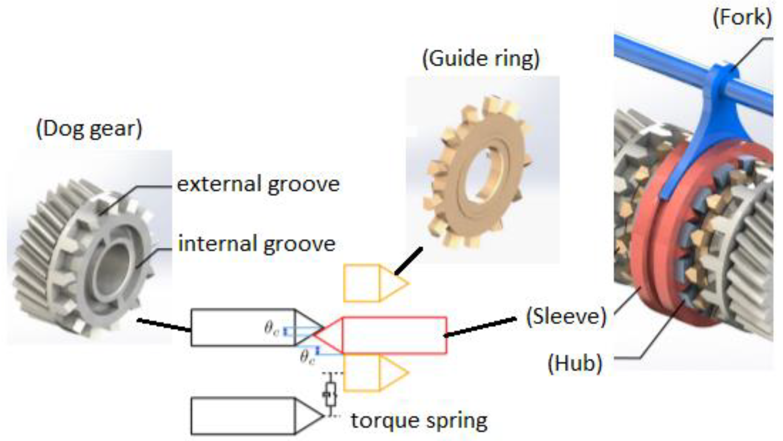
44], on the other hand, explained jerking effects in relation to friction clutch, one-way clutch and types of the driveline. The jerking effects were evaluated under three common shifting scenarios: upshifting during driving, downshifting during driving, and downshifting during braking. In general, smooth shifting is not only beneficial for driving comfort, where it avoids excessive jerking and torque interruption, but it also helps in terms of the overall powertrain efficiency. Thus, a novel clutchless AMT was proposed in [41,42,43] featuring a unique synchronizer called bilateral Harpoon-shift synchronizer. Such a synchronizer uses a torque spring, constructed based on multiple bended coil springs, inside the dog body’s internal groove to keep the dog gear damped to the guide ring (Figure 8). This results in quick synchronization of the guide ring and the dog gear without using frictional cones, and also smooth shifting due to the spring’s damping effect. Additionally, the spring also helps in reducing the required axial force for shifting; minimizing the required DC motor’s work to actuate the fork for shifting. Hence, faster and more efficient shifting process can be done with a compact DC motor. However, the spring also causes additional normal force between the guide ring and the sleeve, and this causes friction force between them during the shifting process. This eventually leads to an extra load that must be overcome by the motor.
Another novel synchronizer design that featured springs inside it was also presented in [45]. Meanwhile, the work in [46] reported the optimization of the gearshifting with the objectives to minimize shifting time, friction work, due to the engagement and disengagement of the clutch during shifting, and jerking. The optimization was conducted using the Legendre pseudospectral method and the gearshifting model was simplified as two degree of freedom (2-DOF) and 4-DOF dynamic models based on a friction clutch and a sleeve shifting mechanism in a two-speed transmission. The results were divided into four different patterns: the least shifting time, the least friction work, the least jerking, and finally, the compromised solution. In the compromise solution, obtained in the 2-DOF model simulation, the shifting time was recorded at 0.92 s, with the square of continuous jerking measured at 0.48 (m/s3)2, and the friction work at 1856 J. In the work, however, no detailed descriptions of the actual actuators used for the clutch and the gearshift sleeve was provided, which can be the focus for future works.
Subsequent research work performed to analyze the performance of shifting mechanism was described in [47,48], where a two-speed dry clutch inverse AMT (I-AMT) was used to vary the gear ratios with very minimal torque interruptions with help from two one-way clutches. The one-way clutches, on the other hand, were integrated into the first gear and the second gear separately, hence the shifting can be achieved by actuating only a single dry clutch. Prior to that works, another study has been carried out, as described in [50], to evaluate the clutch control of a wet dual clutch two-speed transmission for EV application. The objective of the study was to experimentally quantify the clutch control’s performance in terms of jerking and engagement time. However, because of the usage of the wet clutch, some power was lost due to the clutch actuation. Not only that, but the gearshift quality was also less desirable due to the high jerking at around 10 m/s3, signifying noticeable torque interruption during the shifting. Besides, the sticking characteristics of the wet clutch, due to its hydraulic system, caused difficulty to optimize the clutch control for minimum jerking and engagement time. For improvement, other type of clutch, like a dry clutch system with electro-mechanical actuator, can be implemented, so that the clutching and gearshifting can be precisely controlled based on the motor’s torque to minimize jerking and shifting time. Returning to the work explained in [47,48], a dry clutch was used, and its slip control was optimized using high-order disturbance observer to minimize jerking and shifting time, and the clutch control was then tested experimentally in a small EV during upshifting and downshifting. The dry clutch was actuated by a DC motor. The results were encouraging, with the jerking measured at most around 3 m/s3, which is significantly lower than the widely accepted threshold of 10 m/s3. Nevertheless, the operation of I-AMT involved frequent slipping in the dry clutch, hence its durability is expected to be compromised. This leads to the possible increase in the maintenance cost against a simpler single-speed transmission EV powertrain. Thus, detailed study in this aspect is crucial to quantify its long-term operation. Further studies on optimizing the gearshifting mechanism were explained in [49], in which the application of torque sensor was proposed in a two-speed DCT so that precise clutch engagement force can be regulated to fit the desired clutch torque for optimum shift quality. The torque sensor allowed precise real time torque measurement which is crucial to regulate the clutch engagement for optimum engagement time with minimum jerking. However, the application of torque sensor required significant cost, which will increase the transmission’s cost tremendously. This unfortunately makes the option of implementing the torque sensor in the actual transmission impractical.
More advanced studies related to EV powertrain with two-speed discrete transmission focused on the shifting strategy that adapts driver behaviors are described in [51]. Previous studies on the methods to recognize driver behaviors can be read in [52,53,54], covering its application in a fuel cell vehicle and HEV, but none of them was conducted specifically for EV powertrains with two-speed transmissions. However, all of the literatures have certain similarities, in the sense that, the throttle opening rate was used as the indicator for the behavior, and then fuzzy logic was applied to predict the suitable driving style corresponding to the modified standard driving cycles based on driving aggressiveness. Subsequently, the baseline driving style (usually established based on conventional practice) was optimized in the literatures by embedding the correcting factor representing the fuzzy logic’s output. Therefore, in [51], they also proposed a predictive model based on a fuzzy neural network (FNN) to recognize the driver’s intention via the actual throttle opening rate. Simultaneously, the learning vector quantization neural network (LVQNN) method was used to select the appropriate driving cycle by comparing the actual vehicle speed data against three predetermined different driving cycles. These predetermined cycles were obtained offline based on samples generated from the driving cycles of New York City Cycle (NYCC) UDDS and HWFET. Finally, a correcting factor, representing the outputs from FNN and LVQNN, was introduced to the baseline shifting strategy to optimize it for efficiency and driving performance. The baseline shifting strategy was formulated by taking into account the motor’s efficiency, throttle opening and battery’s SOC at 40% and 70%. Comparison between the baseline shifting strategy with and without the correcting factor, through simulation and dynamometer testing, showed an average efficiency improvement of up to 2%, proving the benefits of adapting driver behaviors in the shifting strategy.
A summary of the works related to the gearshifting mechanisms and the adaption of driver behaviors in [41,42,43,44,45,46,47,48,49,50,51] is presented in Table 3. In terms of gearshifting mechanisms, the works reviewed here mostly discussed their standalone performance in terms of jerking and shifting time, while limited discussions were carried out to evaluate their performance when integrated in a powertrain system. This means that the question on the potential improvement efficiency and driving performance in a complete powertrain system is still not properly answered. Nevertheless, with the numerous novel designs of gearshifting mechanism proposed recently by the researchers, the outlook of developing and implementing multispeed discrete transmission, especially two-speed transmission, in a commercialized EV looks promising.
Overall, it can be summarized that the research works on multispeed discrete transmission for EV mainly focused on the implementation of two-speed discrete transmission which can be in the form of AMT or DCT. The two-speed design is very compact, which means the additional weight relative to the usual single-speed transmission can be kept to a minimum. Besides, the two gear ratios provide the necessary flexibility in the EV driving modes’ selection for optimum efficiency and driving performance. The main challenge, however, is how to optimize the gear ratios and the shifting strategy so that the gains in powertrain efficiency and driving comfort can be maximized. Several optimization methods have been implemented to optimize the gear ratios and the shifting strategy, and the results highlighted the capabilities of the two-speed transmission to reduce the power consumption by up to 16% for some driving cycles. However, more work is still required to evaluate the operation and controls of the gearshifting mechanisms in a complete powertrain in terms of efficiency and driving performance. For now, the studies on gearshifting mechanism mostly focused on assessing its jerking and shifting time, with very limited discussion to answer question on its contribution to the overall powertrain’s efficiency.

4.2. Continuously Variable Transmission (CVT)

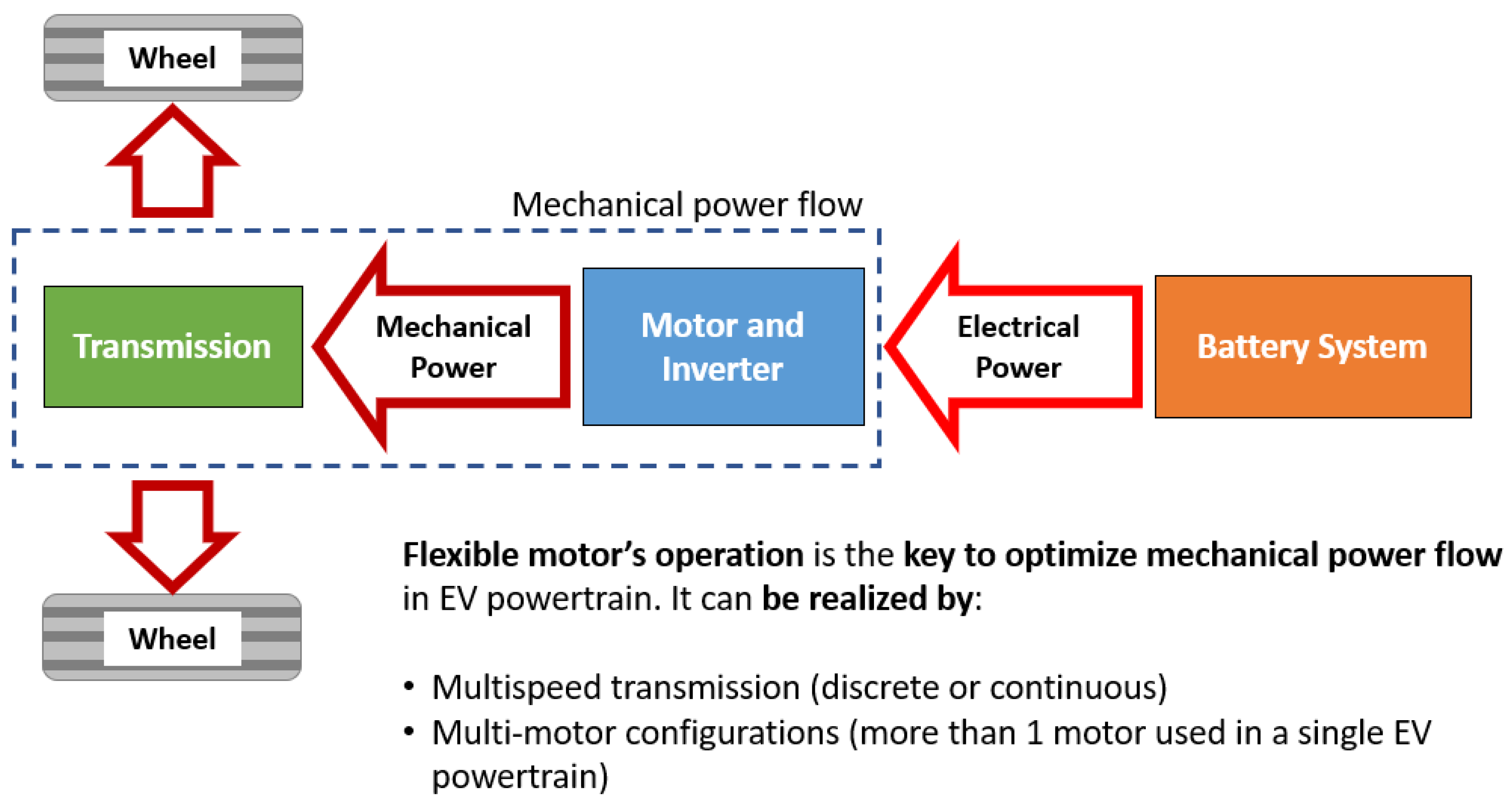
The main motivation of utilizing CVT in EV, identical to the multispeed discrete transmission, is to provide variable transmission ratios so that the motor can operate optimally for diverse driving conditions. In general, there are many types of CVT available for automotive application, but in this review paper, the focus will be on CVT that uses pulleys and metal belt which is the most widely used type currently in automotive. Unlike multispeed discrete transmissions, CVTs with metal belts offer a continuous ratio range, which mean more ratios are available to be chosen to suit the driving conditions. In this sense, a CVT is more flexible than any multispeed discrete transmission, hence, the motor has a much better chance to operate optimally for a longer duration of the driving. However, this type of CVT has certain limitations in terms of power loss in the metal pushing V-belt, or metal chain, used to transmit the torque between the primary pulley; connected to the motor, and the secondary pulley; connected to the vehicle’s wheels. The loss is caused by a portion of motor power consumed to produce the required high clamping force to clamp the belt for the torque transmission between the pulleys. Research in [55] discussed the possibility of controlling the appropriate CVT ratio using fuzzy logic based on the motor’s efficiency mapping as the reference. The fuzzy control algorithm was tested in a simulation model developed based on three driving routes differentiated in terms of road gradients. While the controller helped in enhancing the motor’s efficiency throughout the routes, more detail studied are still required particularly for the ratio and clamping force actuation system of the CVT which was not explained in the paper. Subsequently, in 2017, ref. [56] suggested that a CVT, with a possibility to clamp the belt using an electro-mechanical actuation system with self-lock capability, has the potential to increase the powertrain efficiency. They explained that, unlike conventional CVT that uses engine power to generate hydraulic pressure to clamp its metal belt, such CVT eliminates the required power consumption for the clamping since the self-lock mechanism can held the clamping force. Thus, more power can be transmitted to the wheels, and its ratio can also be selected more efficiently. For an EV, this is particularly beneficial since the motor can operate with high flexibility, resulting in improved powertrain efficiency and increased driving mileage. However, to incorporate the self-locking mechanism required extensive design modifications on the CVT’s pulleys as well as integration of the DC motor to actuate the mechanism accordingly.
Next, refs. [57,58] reported their research involving an evaluation of four different DCTs and a CVT applied in an EV. The four DCTs were differentiated in terms of the number of gear ratios (from single to four-speed), and the size of the gear ratios were determined based on the gradient climbing requirement (first gear), high speed driving (top gear) and the progression factor for the intermediate gears. Thus, the gear sizes, as well as the gearshifting strategy, were not optimized based on suiting any driving cycle. The ratio range of the CVT, on the other hand, was defined based on the continuous ratio range between the first and the top gears of the DCTs. In addition, the CVT was also considered to use electro-mechanical actuation system, instead of the conventional hydraulic system, to vary its ratio and to clamp the belt. Therefore, its efficiency was considered to be significantly higher as compared to the existing CVT used in any ICE vehicle. Also, the manufacturing cost for the CVT was considered to be lower than the two-speed transmission in the research. All the transmissions were then simulated based on a hybrid driving cycle established by combining FTP-75 and HWFET. The results showed that, CVT was the best performer in terms of efficiency for a B-segment car, reduced the power consumption by 31.9% against the single-speed transmission, followed by the three-speed DCT (19.1%), four-speed DCT (18.2%) and the two-speed DCT (16.4%). This result highlighted the magnitude of improvement that can be gained by eliminating the losses in the hydraulic actuation system conventionally used in a CVT with metal belt. Moreover, it also emphasized the saturation in the increment of the gear numbers in a multispeed discrete transmission, which in this case, it can be observed by the reduction of the efficiency improvement between the three-speed DCT and the four-speed DCT. This means that the saturation point here is at three gears, and further increases in the gear numbers will only cause significant actuation losses in the additional shifting mechanism added for the extra gear ratios. The rather low saturation point is typical for a small car (i.e., B-segment) due to its narrower range of the power required as opposed to a bigger car (i.e., E-segment). For a E-segment car, the results showed that CVT was the best performer (23.6%), followed by the four-speed DCT (15.2%), three-speed DCT (9.0%) and two-speed DCT (9.6%). This result suggested that the saturation point for E-segment EV could be higher than four gears for a multispeed discrete transmission, which is logical considering its wider range of power required as opposed to B-segment car. Based on these results, CVT seems more promising, provided that a reliable electro-mechanical actuation system can be successfully integrated in its pulleys system. To achieve this, further research works are still required, especially in the areas of the workability and durability of the electro-mechanical actuation system in the CVT, since such actuation system is still relatively new and has not been implemented previously in any commercialized CVT with metal belt.
Other works discussing the application of CVT in EV powertrain were presented in [59,60]. In [59], the potential of CVT’s continuous ratio range to improved EV power consumption was assessed against the single-speed, two-speed AMT and two-speed DCT EV powertrains. In the assessment, all types of transmissions were considered to have the same constant efficiency of 97%. The assessment was conducted based on an analytical model of the motor’s efficiency, and it showed that with CVT, the powertrain efficiency can be improved by about 3% for WLTP cycle against the other discrete multispeed transmissions. However, more detail analysis, particularly on the CVT’s efficiency, is required, because the application of CVT conventionally involves high hydraulic pressure for clamping and ratio shifting. Thus, without optimization on the hydraulic actuation system, it is inappropriate to assume that the CVT has the same efficiency as the discrete multispeed transmission. Subsequently, in [60], the CVT was considered to be using the optimized electro-hydraulic actuation system (more compact and requiring low power for generating the belt’s clamping force) and the novel single loopset belt (as opposed to the typical metal pushing V-belt, hence more compact design and reduced power losses). On top of that, the possibility of downsizing of the motor was also studied, where it was achieved through the reduction of the rotor’s diameter and inertia. Nevertheless, the work did not take into account the optimization of the transmission ratios and the shifting strategy. When the powertrain was simulated under WLTC, it showed a 12.7% efficiency improvement against the EV powertrain with single speed transmission. That, however, was less than the two-speed AMT that produced a 13.5% improvement. The lower improvement was very likely caused by the hydraulic actuation system. Even though the system was optimized, the required belt’s clamping force was still very high (depending on the EV motor’s torque) and must be provided continuously during operation. Hence, continuous power to generate the clamping force, albeit lower thanks to the optimization, was still needed. The AMT, on the contrary, used geartrain to transmit the power, hence no requirement for the belt’s clamping force. This means that the continuous power for the clamping force was eliminated entirely. This situation also affected the power flow in the powertrain, which can compromise the driving performance and this can be observed in the 0–100 km/h acceleration time, where the AMT and the single speed transmission yielded 6.9 s, while the CVT achieved 7.4 s. Based on the results, it appeared that AMT is the better transmission for EV than the CVT, although it must be noted that with the latter, it is possible to eliminate torque interruption during ratio shifting.
Research work described in [61] explained optimization and discretization of the CVT ratios so that optimum power consumption can be realized with as minimum shifting as possible. The CVT featured an electro-hydraulic actuation system, where an electric pump was used to precisely control the required hydraulic pressure for clamping and ratio shifting (Figure 9). The rationale of discretizing the ratios was to avoid too frequent shifting would lead to uncomfortable driving due to jerking, as well as power losses in the hydraulic actuation system. The discretizing process started by first establishing the appropriate number of ratios based on the relation between the energy cost and the ratio number. Hence, the number of ratios was set at four, and the ratio sizes were determined through an equal ratio series method. Then, these ratios were optimized using GA for optimum efficiency when undergoing a combined driving cycle that comprised of UDDS, NYCC and HWFET. For the driving cycle simulation, three ratio shifting strategy models were employed; first, continuously variable ratio shifting strategy, where the best ratio was selected continuously during driving for maximum efficiency, second, the discrete ratio shifting strategy based on the ratios established through the equal ratio series method, and third, the discrete ratio shifting strategy based on the ratios optimized through GA. Comparison between the results confirmed that the third strategy performed the best, with the minimum total power consumption and average jerking, measured at 8.10 kWh and 4.32 m/s3, respectively. The first and second strategies, meanwhile, recorded 8.16 kWh and 5.35 m/s3, as well as 8.69 kWh and 4.65 m/s3, respectively. To summarize, the work reported in [61] highlighted two very important findings. Firstly, CVT provides a continuous ratio range, hence the ratios can be discretized and optimized to suit diverse vehicle parameters, which means the same CVT can be implemented for several type of EVs for optimum driving performance and efficiency. Secondly, high ratio number presents better flexibility for motor’s operation, but it also leads to complicated shifting logic which will cause too frequent shifting, resulting in the power losses in the actuation and compromised driving comfort. This presented an opportunity to apply the same CVT with different sets of discretized ratios to suit the requirements of diverse EV segments, which can contribute in terms of cost reduction in the transmission production.
One of the latest works describing the application of CVT in an EV powertrain can be accessed in [62]. This work presented an optimization of the EV ownership cost by taking into account the components’ cost and the electricity cost for all the components involved in the powertrain; battery, motor (with inverter), and, CVT. The optimization was carried out using convex programming design optimization, with the targets to minimize the cost; by a means of optimizing the size of the motor and battery, without compromising the driving performance in terms of 0–100 km/h acceleration time (at most 11 s), top speed of 165 km/h and gradeability of 30%. In the work, three powertrain models were evaluated; first, the base powertrain model taken from the actual EV that used single speed transmission, second, the modified powertrain model, which essentially the based model with CVT instead of the single speed transmission, and lastly, the optimized powertrain model, in which the CVT ratio as well as the size of the main powertrain components were optimized based on the actual driving data obtained from road and dynamometer tests. Similar to [61], the CVT evaluated in [
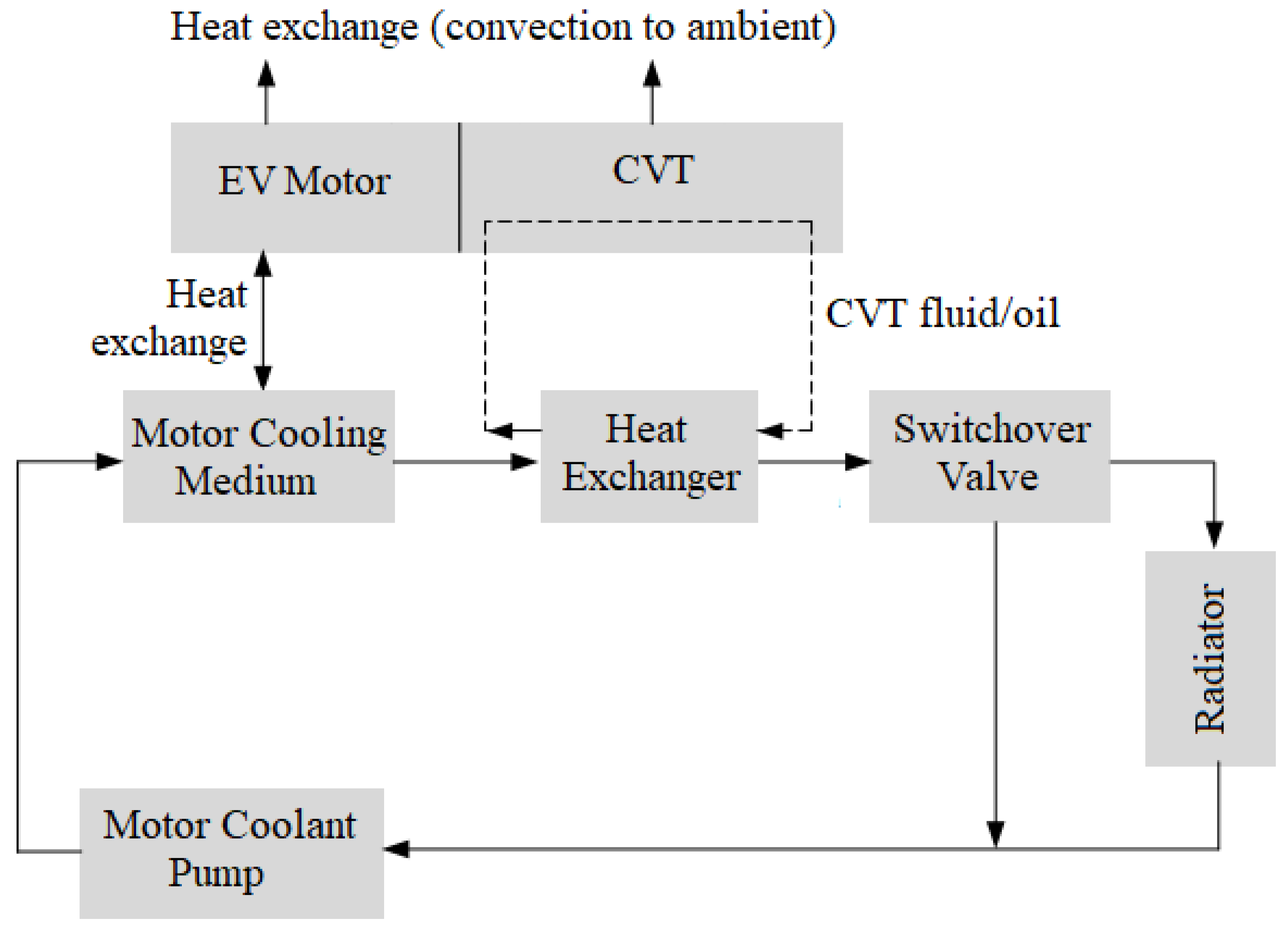
62] also used electro-hydraulic actuation system for belt’s clamping and ratio changing. However, the design integrated the cooling system of both the CVT and the motor, where the heat from the CVT fluid was dissipated to the motor’s coolant through a heat exchanger, and then the coolant would be cooled down by the radiator (Figure 10). As a result, an extra radiator for the CVT was unnecessary, and this led to a more compact and cost-effective thermal management system. By simulating all the powertrain models under WLTC, the results showed that the optimized powertrain model performed the best in terms of efficiency (11.19 kWh/100 km, means 2.1% improvement against the base model with 11.43 kWh/100 km) and cost (2% cost reduction against the base model). In terms of cooling power consumption, the optimized model also gained an improvement of 30% as compared to the base model, and this means that the integrated thermal management system was not only cost effective, but it was also very efficient in controlling the operating temperature of the motor and the CVT. Besides, the integrated system also presents an opportunity for further integration with the battery’s thermal management system which will potentially lead to further improvements in terms of cost and efficiency. Nevertheless, power losses in the hydraulic actuation system can still be expected, and it is interesting to evaluate how the optimized CVT performs against a two-speed transmission with optimized gear ratios.
Another paper that discussed the potential cost benefit of using CVT in an EV can be found in [63]. Here, the application of CVT was complemented by the hybrid battery technology that incorporated a supercapacitor, and the cost benefits considered not only the component and electricity cost, but also the battery replacement cost. The CVT used an electro-mechanical actuation system for clamping and ratio changing, which means it featured a self-lock mechanism to maintain the belt’s clamping force without using hydraulic pressure. The actuation system comprised of two DC motors with presumably power screw mechanism, each for actuating the primary pulley and the secondary pulley. So, theoretically, it was more efficient than the CVT described in [61,62] thanks to the self-lock capability. However, detail description on the CVT’s actual electro-mechanical actuation system was not described in the paper. The CVT losses model was developed to estimate its efficiency, and based on the model, the efficiency was estimated between the range of 78% to 89%. When simulated under a combined driving cycle of HWFET and FTP-75, the usage of the electro-mechanical CVT reduced the motor’s losses by 37.9%, which was translated into 8.3% improvement in the power consumption of the vehicle when compared against single speed transmission. In terms of battery degradation, using CVT reduced the degradation by 7.2% as opposed to the single speed transmission, and, with the proposed hybrid battery technology, the improvement rate can be increased further to 17.5%. The battery degradation was defined in terms of capacity loss percentage, estimated using the LiFePO4 cell’s dynamic model that took into account the charging rate and the battery temperature during driving [64,65]. The latest review paper providing further descriptions on the estimation techniques for battery state of health in an EV can be accessed in [66]. Finally, in terms of cost benefits for 11-year of operation, when compared the application of CVT against single speed transmission (both using the hybrid battery technology), a saving of around USD 4541 can be expected for the consumers for the battery cost, resulted from the reduction of the required battery capacity due to the improvement in the powertrain efficiency. In addition, a further saving of USD 1768 can also be gained due to the reduction in the electricity cost. In overall, after reflecting the battery replacement cost as well as the penalty cost for using CVT, the total cost benefit was estimated at USD 3178 for 11-year of operation.
More advanced research on CVT application in an EV powertrain was explained in [67] which involved the optimization of an eco-driving strategy. The optimization objective was to minimize the reduction of the battery’s SOC during the driving by taking into account not only the motor’s efficiency, but also the instantaneous SOC as well as the efficiency of the CVT. Here, the CVT efficiency model was developed using mathematical equations introduced in [68,69,70]. NEDC was used as the driving cycle, in which it was divided into three driving conditions, namely, constant driving speed, acceleration condition and deceleration condition. In these conditions, the powertrain efficiency was analyzed for different SOC, CVT ratios and ambient temperature. One interesting aspect of this work is that it analyzed the SOC until the range of below 10%. Such SOC is rarely discussed in other literatures because in the actual application, the cut-off set point for the battery is usually set at around 20% to avoid any risk of damage. The analysis showed that, low SOC (at about 10%) decreased the powertrain efficiency by 33.12% and the acceleration time became longer by 68.8%. Such inefficiency was caused by the degradation of the battery that becomes significant starting from 10% SOC and lower. Because of the degradation, the battery internal resistance increases and its open circuit voltage decreases, which resulting in the increase losses percentage in the current flow from the battery to the EV motor. Moreover, at 10% SOC, the battery also became more sensitive to ambient temperature, which caused the losses in the current flow to increase even further. Above 10% SOC, however, the ambient temperature was insignificant in influencing these parameters, and the battery degradation was negligible, hence powertrain efficiency became more stable. By incorporating this knowledge in the eco-driving strategy, the constant driving speed condition in the NEDC can be increased from 61 to 70%, and the total driving time can be reduced by 12.1%, resulting in a more economical driving. This study highlighted the importance of eco-driving method that can only be implemented if the EV powertrain has the required flexibility in providing diverse driving modes. In addition, the study also served as the starting point to integrating battery’s health conditions in the powertrain analysis.
To summarize, CVTs can provide better flexibility in ratio selection due to their continuous ratio range as opposed to any multispeed discrete transmission. This flexibility allows the EV’s motor to operate optimally for various driving conditions. However, for the actual operation of the CVT in an EV, an appropriate shifting strategy must be formulated, either continuous shifting or discretized shifting. The first strategy leads to better motor efficiency, but requires higher actuation power and advanced shifting logic. The second strategy, on the other hand, compromises the motor’s efficiency slightly as compared to the first strategy, but its shifting logic can be made simpler and the actuation power consumption can be reduced. Another area that has to be studied is the actuation system for ratio shifting and belt’s clamping in the CVT. Here, three possibilities can be explored; either optimizing the hydraulic actuation system typically used in the existing CVT, or implementing electro-mechanical actuation system to replace the hydraulic actuation system in the CVT, or, developing geartrain-based design of CVT. By optimizing the hydraulic actuation system, the power required to generate continuous pressure for CVT ratio and belt’s clamping force can be reduced. However, since the required belt’s clamping force is still very high (around at least 10 kN and it increases with the increment of the motor’s torque), thus the amount of required power will always be significant. As compared to any multispeed discrete transmission, such issue is eliminated thanks to the application of geartrain. Implementing electro-mechanical actuation system, on the other hand, eliminates the power requirement for the continuous pressure due to its self-lock mechanism, but, designing and integrating such system in a CVT requires extensive study to confirm not only its workability but also its reliability. A summary of the literature review on the CVT application for EV powertrains can be found in Table 4.

4.3. Multi-Motor Configuration

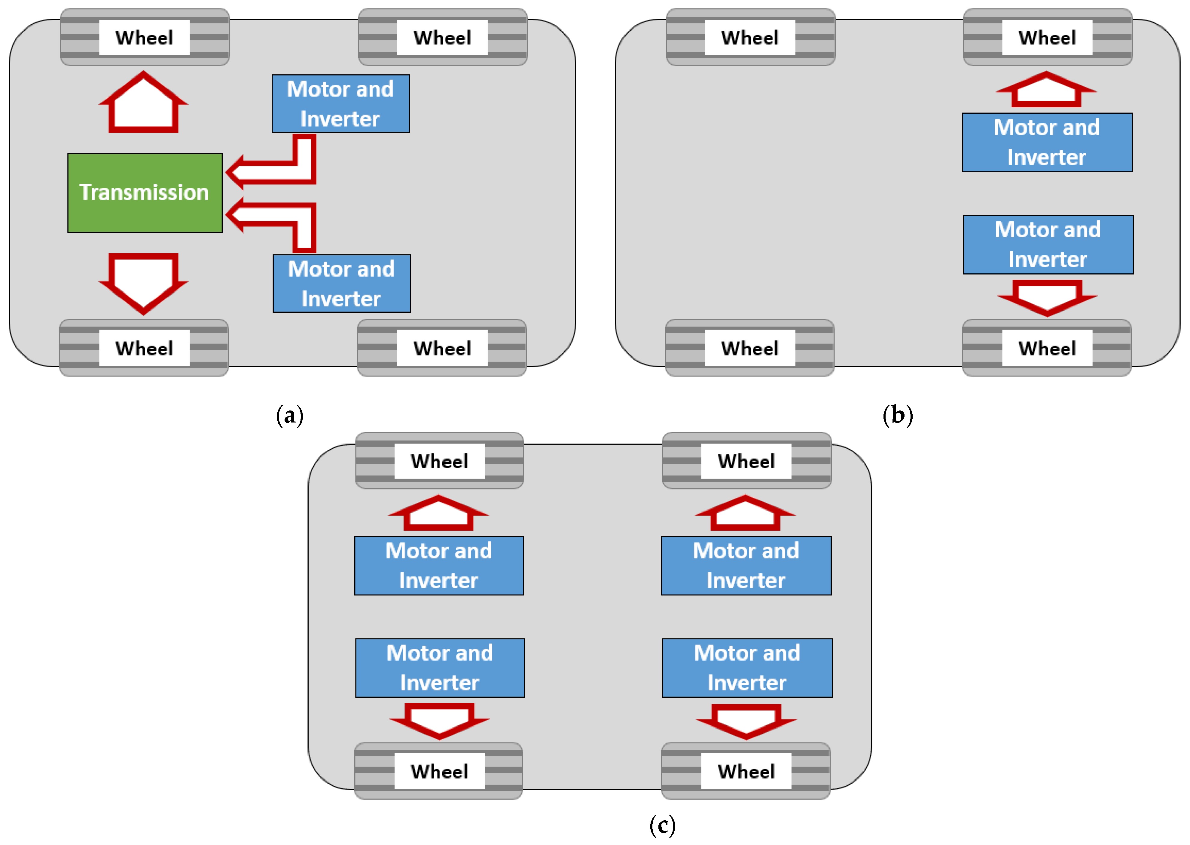
The idea of optimizing EV powertrains using a multi-motor configuration involves properly distributing the driving loads, typically between two motors or four motors, so that they can operate optimally under various driving conditions. Additionally, in some situations, these motors can also provide boosting power for faster acceleration and higher top speed. As a result, the capacity of the motors can be reduced without compromising the driving performance and this leads to potentially significant cost savings. There are three common types of multi-motor configuration studied for EV; the first one is two-motors configuration where both motors are connected to a transmission before the wheels, the second is the two-motors configuration where both motors are directly coupled to the wheels, and finally, the four-motors configuration where all motors are directly coupled to the wheels (Figure 11).
In the two-motors configuration where two motors are connected to a transmission before the wheels, allowing torque and speed couplings between the motors is crucial to suit diverse driving conditions. As shown in Figure 12, torque coupling means the torque from the ICE and the motor is combined through direct gearwheel, resulting in the shared torque requirement between them at the wheels. Equations describing the output torque and speed of the coupling are shown in Equations (1) and (2). Speed coupling, on the other hand, means the speed of the ICE is combined with the motor’s speed through planetary gearset, resulting in higher speed, hence higher power, at the wheels (Figure 13). Equations (3) and (4) explain the relationship between the motors’ inputs and the coupling’s outputs. Torque coupling is generally useful for start-stop condition, while speed coupling is usually applied to achieve fast acceleration and high-speed driving. Latest examples for the optimization of HEV powertrain configurations can be read in [71,72,73]. In Peng et al. [71], various HEV powertrain configurations based on CVT with metal belts and discrete gear automatic transmissions as the torque coupling, and a planetary gearset as the speed coupling, were generated using a fundamental matrix. In the work, feasible driving modes of these configurations were determined using an adjacency matrix, and based on these modes, the powertrain configurations were evaluated and compared against the benchmark configuration (Figure 14a) in terms of 0–100 km/h acceleration time and average power consumption under WLTC. The results demonstrated that the best configuration, as depicted in Figure 14b, managed to reduce the acceleration time and the average power consumption by 8.7% and 12.2%, respectively. Such improvements were possible because of the flexible driving modes provided by the proposed configuration that resulted in the reduced ICE power required for some driving conditions (due to the planetary gearset at the motor’s output), and more efficient regenerative braking (due to the several torque coupling possibilities at clutch C3 and C2). Results in [71] are also consistent with those discussed in [73], where it was found that the combination of CVT and planetary gearset is crucial to optimize the HEV’s efficiency for various vehicle speeds.
T o u t = R o u t R m o t o r 1 T m o t o r 1 + R o u t R m o t o r 2 T m o t o r 2
ω o u t = R m o t o r 1 R o u t ω m o t o r 1 = R m o t o r 2 R o u t ω m o t o r 2
T o u t = 2 R c a r r i e r R s u n T m o t o r 1 = 2 R c a r r i e r R r i n g T m o t o r 2
ω o u t = R s u n 2 R c a r r i e r ω m o t o r 1 + R r i n g 2 R c a r r i e r ω m o t o r 2
Outcomes in [71,72,73] highlight the importance of a proper strategy for torque and speed coupling between two or more motors that can lead to flexible driving modes for an EV. Thus, to evaluate its implementation in EV [74,75,76,77], studied the effects of using multi-motor configurations in EV powertrain on the power consumption based on several driving cycles. In [74], the same two motors were used in a two-motor EV powertrain configuration, and the powertrain was evaluated based on three different torque distribution strategies between the motors, where the final strategy was optimized using adaptive non-linear PSO. In [75], on the contrary, two motors with different maximum torque were used where they were connected through planetary gearset. Here, only speed coupling is possible, and these motors were controlled using a combination of speed feedback control strategy and torque feedforward control strategy to minimize jerking during the shifting of the driving modes. Other papers describing the implementation of dual motor configuration with planetary gearset can be read in [76,77], and because they allowed only speed coupling, the flexibility in terms of driving modes was limited.
Meanwhile, in [78], three configurations of two motors EV powertrain without multispeed transmission were considered; configuration for torque coupling (Figure 15a), configuration for speed coupling (Figure 15b), and a configuration for both torque and speed couplings (Figure 15c). Therefore, this configuration offered significant improvement in driving modes flexibility. In the first configuration, a single planetary gearset was used, in which the first motor was directly connected to the gearset’s sun gear, while the second motor was connected to the same sun gear through a clutch. For the second configuration, two planetary gearsets were used with a brake at their ring gears. The first motor was meshed to the sun gear of the first planetary gearset, and the planet carrier here was rotatable. The second motor, on the contrary, was connected to the second planetary gearset’s sun gear, where its planet carrier was fixed to the casing. The engagement of the brake on the ring gears of both gearsets was used to control the speed coupling in the configuration. Finally, the third configuration was essentially a heavily redesigned second configuration, that now has a clutch between the sun gears, and the rotation of the second planet carrier was controllable through another brake. As a result, the third configuration was more flexible, thanks to its capability to provide both torque (through the clutch between the sun gears) and speed couplings (through the brake at the ring gears). The benchmark in the study was a single motor EV powertrain with single-speed transmission. The gear ratios of all these powertrain configurations were optimized using non dominated sorting GA (NSGA-II) for optimum efficiency under UDDS, HWFET and NEDC. Compared to the single motor EV powertrain with single-speed transmission, in average, the single motor with two-speed transmission was about 2% more efficient, while the first, second and third two motors EV powertrain configurations were 5.77, 5.57 and 6.40% more efficient, respectively. It was interesting to note here, that the efficiency of the first two motors configuration (capable of torque coupling only) and the second configuration (capable of speed coupling only) were pretty much the same, although, in terms of mechanical system, the latter was significantly more complex than the former due to the application of two planetary gearsets. Next, for the second configuration with speed coupling and torque coupling options, the design was much more complex since it required three actuators for the two brakes and a clutch. With the difference of only 0.63% in terms of efficiency gain between the first and the third configurations, it was logical to choose the first configuration for an actual implementation. Therefore, in the future work for [78], more studies can be carried out to compare the driving and gearshifting performance of these configurations so that more aspects can be evaluated.
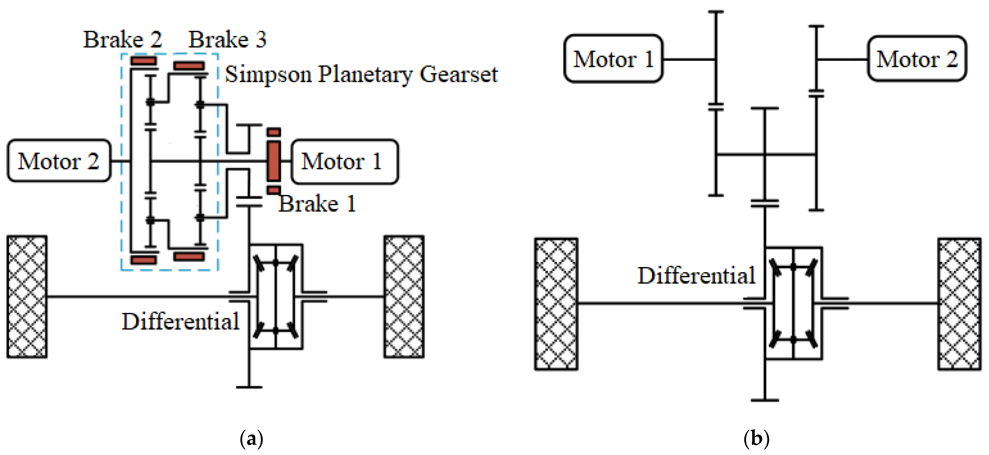
Next, in a latest work described by [79], a two-motor configuration based on a Simpson planetary gearset was proposed in a two-motor EV powertrain configuration. Unlike the configuration described in [78], this proposal provided two gear ratios in the powertrain, resulting in more flexibility for the driving modes. The Simpson planetary gearset consisted of two planetary gearsets with a brake for each set’s ring gear, and another brake was used at the first motor’s shaft. The ring gear of the first planetary gearset was connected to the second motor, and the ring gear of the second planetary gearset was connected to the first gearset’s planet carrier. The planet carrier of the second gearset, on the other hand, was connected to the wheels through a differential, while the sun gears of both planetary gearsets was connected to the first motor. Figure 16 depicts the diagram of the Simpson planetary gearset configuration proposed in [79], which was capable of providing six driving modes (two modes with two motors, and four modes with one motor). The two modes with two motors represented the possibility of torque coupling and speed coupling of the motors, and the four single-motor modes represented the power flow from the first and second motor through two-speed gear ratios. The powertrain configuration’s motor power and gear ratios were optimized using GA for minimum average efficiency in six driving cycles (LA92, JP1015, NEDC, WLTP and HWFET), high gradeability (40% at 10 km/h), high top speed (at least 190 km/h) and fast 0–100 km/h acceleration time (at around 10 s). The proposal was then compared with the typical parallel axle dual motor configuration with fixed gear ratio for evaluation. In terms of acceleration, the proposal provided faster 0–50 km/h acceleration time, but no significant difference was observed for the 0–100 km/h. For the average efficiency, the proposed Simpson planetary gearset configuration was more efficient than the typical parallel axle dual motor configuration by around 2.88 to 8.33% when employed in driving cycles with frequent acceleration and deceleration. However, in a driving cycle with relatively constant vehicle speed (like HWFET), the typical configuration was slightly more efficient by 0.45%, very likely due to the losses in the planetary gearsets. Moreover, the proposed configuration also required three actuators for the three brakes to properly control coupling between the two motors. In this aspect, advanced control algorithm for the actuators is crucial to ensure that they can be operated systematically not only for powertrain efficiency but also for driving comfort by minimizing the jerking during the driving mode shifting. Thus, in the future study, it is imperative to evaluate the workability and control of these actuators so that their performance in terms of powertrain efficiency, jerking and shifting time can be quantified and compared.
The subsequent work on multi-motor configuration is described in [80], which like [79], studied the possibility of applying an EV powertrain with a two motor configuration and a multispeed discrete transmission, in this case four speed AMT. The powertrain was applied in a city bus for a specific Nuremberg City Cycle and also for NYCC, where the focus was to optimize the driving strategy by properly coordinating the gearshifting. This was to avoid gear hunting, which not only affected the powertrain efficiency, but was also detrimental to the driving comfort. Next, in [81], the objective was to determine and compare the performance of the configuration against single motor configuration with four-speed AMT. The study started by generating two optimized configurations of two-motors-four-speed-AMT EV powertrain, where the optimization objectives were to obtain minimum operating cost (defined as minimum total power consumption for the aforementioned driving cycle) and high driving performance (defined as the minimum acceleration time for 0–40 km/h). The control variables of the optimization were motor scale factor; expressed as the ratio of motor 1’s power divided by the power of motor 2, and the four gear ratios of the AMT. The optimum combinations of the variables to meet the optimization objectives were determined using NSGA-II. As a result, three powertrain configurations were finalized; Configuration 1 that consisted of one motor configuration and two optimized gear ratios, Configuration 2 that consisted of two motors configuration with the motor scale factor of 0.42 and four optimized gear ratios, and Configuration 3 that consisted of two motors configuration with the motor scale factor of 1.00 and four optimized gear ratios. All of them achieved the same acceleration time of 8.5 s, but in terms of power consumption, Configuration 1 recorded the worst at 7.48 kWh, while the second and third configurations managed to improve over the first one by 4.82% and 5.08%, respectively. Next, the optimum driving strategy was formulated for each configuration in terms of shifting schedule and motors coupling modes so that the driving efficiency and performance can be improved further. The simulation results of the three powertrain configurations plus the optimal driving strategy showed that, both Configurations 2 and 3 allowed the motors to operate with at least 85% efficiency rate for 65% of the driving cycle. As a comparison, in Configuration 1, the motor was allowed to operate at the same efficiency rate only for about 32% of the same driving cycle. Because of that, the total power consumptions obtained for Configurations 2 and 3 were lower than Configuration 1, at 7.219 kWh and 7.216 kWh, against 7.627 kWh, respectively. Nevertheless, it must be mentioned that in Configuration 1, the gear shifting occurred only 46 times during the cycle, which was significantly lower than 84 and 80 each for Configurations 2 and 3. These findings indicated that the one motor EV powertrain configuration with two-speed transmission is potentially advantageous in terms of overall cost (production, operation and maintenance costs) than those two motors configurations, even though it performed the worst in terms of efficiency. Not only that, the acceleration time was also the same for all configurations, and this reinforce Configuration 1 as the overall best choice as opposed to the other two. Therefore, further study on the operation cost can be carried out in the future by relating the data of the gearshifting frequency and the wear and tear of the shifting mechanism. Next, the shifting performance especially in terms of jerking must also be evaluated for all the configurations so that more aspects can be compared to determine the overall best configuration between the three. Other works describing the application of multi-motor configurations with multispeed transmission can also be read in [82], which reviewed the methodologies of the multi-motor configurations, and [83], which presented an optimization of gear ratios and torque distribution of two-motor EV powertrain configuration with two-speed transmission using a surrogated model developed based on an effective adaptive sampling method.
Apart from using two motors powertrain configurations, there were also other studies performed to evaluate the application of four motors in the EV powertrain. For instance, in [84,85], four motors were used with each of them assembled in the EV’s four wheels (Figure 17). The main idea here was to split the weight distribution of the powertrain evenly to all wheels, thus enabling the increase of driving flexibility without the application of bigger motor and transmission. Each motor was also coupled to a two-speed AMT designed based on planetary gearset, where the appropriate gear ratio was actuated using DC motor and worm gear mechanism. In addition, the gear ratio actuator also featured ball-ramp self-energizing that consisted of translation plate with steel balls and spiral ramps. The purpose of this mechanism was to amplify the clutch engagement force during the gearshifting, resulting in the reduction of DC motor’s required power. To simulate the powertrain performance, the AMT’s gear ratios as well as its complete parameters were determined based on a transmission-equipped wheel hub motor described in [86], while the gearshifting schedule was developed based on the vehicle speed and the throttle position. To simplify the simulation model, a dog clutch model was used as the surrogate model for the proposed gear ratio actuator. Two shifting approaches were applied—synchronous and asynchronous—where synchronous means that the gearshifting occurred simultaneously for the front and the rear wheels, while asynchronous means the gearshifting was done independently between the front and the rear wheels with a delay of 0.2 s. The key benefit lay in the asynchronous approach, which minimized the jerking thanks to the delay that reduced the torque interruption in the front wheels’ gearshifting by compensating it with the torque at the unshifted rear wheels (and vice versa). As a result, the jerking can be kept within the range of 4 m/s3 to 6 m/s3. However, the proposed powertrain configuration involved four independent two-speed AMT actuators, which means, although it was highly flexible in terms of gearshifting, it required sophisticated control logic to avoid too frequent shifting and gear hunting. Too frequent shifting and gear hunting, if not properly optimized, will cause driving discomfort and increased losses in the actuators.
The latest studies on four motors EV powertrain configuration focused on not only achieving optimum efficiency, but also enhancing driving safety and steering assist [87,88]. Unlike the powertrain configuration proposed in [83,84,85], the four motors EV powertrain introduced in [87,88] lacked the gearshifting options since it used single speed transmission. However, the omission of gearshifting options increase its simplicity in terms of operation and controls. In [87], the element of driving safety, together with the optimum efficiency in terms of power consumption, can be realized by implementing integrated motors’ torque vectoring control strategy in the wheels. The integrated strategy was intended to achieve multiple objectives such as reasonable traction torque distribution on the wheels for yaw stability control and steering assists, proper motor’s output torque to enable it to operate at its most efficient range for optimum power consumption, and reducing the wheels’ dynamic slip for driving stability as well as optimum power consumption. The proposed integrated strategy was then compared against the conventional axis distribution and maximization of stability margin strategies through simulation under WLTC, where the results showed that the integrated strategy reduced the wheels slip by 14.38% compared to the axis distribution strategy that led to the improved power consumption by 5.37%. The simulation results were then validated experimentally based on a single seat EV prototype that was driven at 60 km/h on a slippery road and then executing standard lane change maneuver. In the experiment, the wheels slip was reduced by 12.75% due to the implementation of the integrated torque vectoring control strategy as opposed to the axis distribution strategy. Meanwhile, in [88], a fuzzy logic algorithm was applied in the traction distributions on the wheels. The algorithm was responsible to make sure that sufficient traction can be given to each of the wheels to achieve the desired vehicle speed during the driving, while also ensuring that the vehicle trajectory follows the desired driving path. Components of the powertrain used here were optimized using PSO for minimizing the weight of the battery and motors, minimizing drop in the battery’s SOC, and reducing driver steering efforts. With the optimized EV powertrain and the fuzzy logic algorithm for the wheels’ traction distribution, driver steering efforts can be reduced by 78.5% and the driving mileage can be increased even with the reduced size of the battery. The results obtained in [87,88] demonstrated the potentials of implementing independent motors for all wheels not only for efficiency but also for the vehicle handling that can possibly contribute in the vehicle safety and autonomous vehicle technologies. For the future scope, the work in [87,88] can be expanded to evaluate the proposed configuration’s performance in controlling the vehicle maneuvering against conventional traction control methods.
Summary of the reviewed literature on the multi-motor configurations for EV powertrain is presented in Table 5. There are two common multi-motor configurations studied in the literature; the two motor configuration, and the four motor configuration. The objective of the two motor configuration is to allow the operation of one motor to be supported by the other motor through either torque coupling or speed coupling. As a result, the operation of these motors can be optimized for diverse driving conditions. The challenge, however, is to come up with the proper mechanism for the couplings, which typically involves multi clutches and brakes. The next challenge will be to effectively and systematically control these clutches and brakes through actuators so that the driving mode shifting can be executed smoothly and efficiently. Regarding the four motors configuration, the objective is to minimize the transmission power loss, since the motor is coupled directly to each wheel. Besides, the traction on the wheels can also be distributed independently, which can improve not only the power consumption, but also the driving stability and safety. Nevertheless, to achieve these, advanced control algorithm is required to integrate effectively the operation of the four motors at the wheels.

5. Comparison and Future Works Related to the Methods for Optimizing Power Flow in EV Powertrains

In the previous section, the methods to optimize power flow in an EV powertrain are reviewed and divided into three: applying multispeed discrete transmissions, applying CVTs with metal belts, and implementing multi-motor configurations. Although these methods can lead to improvements in driving efficiency and performance, their advantages and disadvantages relative to each other must also be properly assessed. Therefore, in this section, the three methods are compared and evaluated extensively to discuss their potential advantages and disadvantages. Afterwards, key areas for future research works in the context of optimizing EV’s power flow are presented and discussed.

5.1. Comparison of the Methods

Among the three methods, multispeed discrete transmission is the most common one studied by scholars. Within this class, the two-speed transmission is the most popular, which can be described in the form of either AMT or DCT. Most of the works related to the application of two-speed transmission reviewed here involved optimization of the gear ratios and shifting strategy to achieve optimum power consumption and driving performance, in terms of acceleration rate and top speed [33,34,35,36,37,38,39,40]. As a result, the EV powertrain becomes more efficient and more capable, and this opens up the possibility of optimizing the size and capacity of the motor and the battery. Such a possibility is beneficial for production sustainability, because the usage of heavy materials for motors and batteries can be reduced. At the same time, since the two-speed transmission is very compact and shares significant degree of similarity with the traditional one in ICE vehicles, the existing transmission manufacturing process can also be utilized which will be cost-effective for total EV production cost. The significant challenges, however, are the jerking in the gearshifting mechanism, the limited flexibility and the additional maintenance cost for the two-speed transmission.
Similar to multispeed discrete transmission, CVTs with metal belts also involve providing multiple ratios for optimum efficiency and driving performance in an EV powertrain. However, unlike a multispeed discrete transmission, CVTs are capable of providing a continuous ratio range, which addresses the limited flexibility problem faced by the multispeed discrete transmission approach. This presents an opportunity to implement it for diverse driving conditions and various vehicle segments. At the same time, it is also beneficial in terms of production sustainability and technology migration, because of the possibility to reuse the existing manufacturing processes and facilities. This is because the metal belt-based CVT for EV shares a significant number of common components with the existing ones used in ICE vehicles. The main challenges for this type of CVT, however, are its metal belt’s operation and maintenance cost. The metal belt’s operation requires high hydraulic pressure, significantly higher than the requirement for AMT and DCT, for maintaining its clamping force and ratio. In addition, the belt’s operation also inevitably involves micro slippage between its components. These two factors cause transmission loss which is higher than that suffered in AMT and DCT. Also, these factors require slightly costlier maintenance than the other two types of discrete transmission commonly studied for EV application.
The last method reviewed here is the implementation of multi-motor configurations, which can be divided into two typical approaches: two-motor configurations and four-motor configurations. For the two-motor configuration, the possibility for both torque and speed couplings certainly leads to flexibility for various driving modes. However, in some cases, providing either speed coupling or torque coupling can already be sufficient to achieve higher powertrain efficiency than the application of two-speed discrete transmission. The two-motor configuration can also be applied with a multispeed transmission, which can be particularly useful for optimizing the power consumption of heavy vehicles such as trucks and busses. For the four-motor configuration, it allows even more diversity in the driving modes than the two-motor configuration, thanks to the possibility to distribute traction to each wheel independently. This presents an opportunity to optimize not only the powertrain efficiency, but also the driving dynamic of the EV (which is not possible for both the multispeed discrete transmission and CVT) and the motors’ capacity and size. The main challenges of the multi-motor configurations, however, are the complexity in terms of the mechanical design and control due to the application of multi clutches, brakes and EV motors, as well as the production sustainability due to the high number of motors involved. A summary of the comparison between these three proposed methods of optimizing the EV powertrain is presented in Table 6.

5.2. Key Areas for Future Research Works

The latest research works on two-speed transmission for application in EV powertrains reviewed in this paper mostly focused on optimizing the gear ratios for powertrain efficiency and performance. Besides, these works also emphasized the proper gearshifting strategy, which should be formulated accurately by taking into account the road conditions and driver’s input so that a balance between the powertrain efficiency and performance can be realized. This was consistent with the research trends previously discussed and reviewed in [89,90]. However, these works still did not sufficiently discuss the control algorithm of the gearshifting mechanism in detail. Examples of works on this topic can be read in [41,42,43,47,48], though these works evaluated only on the jerking of the mechanism alone without being integrated with the multispeed transmission inside the powertrain. Besides, they also did not assess the effect in terms of transmission efficiency and actuation power consumption. Therefore, in the future, works in the control of the gearshifting mechanism are expected to be intensified.
On the CVT with metal belt for EV powertrains, most of the previous related literatures focused on analyzing and comparing its efficiency and performance against multispeed discrete transmissions and multi-motor configurations. However, due to the application of hydraulic actuation system, the CVT suffered significant power losses, which prompted some scholars to study the practicality of replacing it with an electro-mechanical actuation system. At the moment, very limited works have been carried out to analyze thoroughly the application of electro-mechanical CVT for EV. Based on the latest review paper on an electro-mechanical CVT with metal belt in [91], some of the designs are capable not only of self-locking the ratio and belt’s clamping force, but also precisely controlling them. Controlling the belt’s clamping force, particularly, is the key to optimize the CVT efficiency as well as to optimize the durability of the electro-mechanical actuation system, as extensively explained in [92]. This means that transmission losses can be minimized as much as possible, though thorough studies still need to be performed since electro-mechanical CVT is still not a mature technology and so far, not being implemented for commercialization. Therefore, key research area here is the optimization of the ratio and clamping control algorithms in the electro-mechanical actuation system for CVT with metal belt. Another area that can be focused on is the possibility of implementing geartrain-based CVT, which eliminates the application of the metal belt entirely.
In the context of multi-motor configurations, key research areas that can be pursued are the control algorithm for traction distribution on the wheels and the durability of the powertrain system. Apart from optimum power consumption and driving performance, multi-motor configuration offers the chance to implement steering assist and wheels’ traction control. However, since the powertrain is now attached directly to wheels, it now becomes part of the unsprung mass. As a result, the powertrain is now subjected to harsh operating condition involving direct vibrations caused by the road surface, as well as water splash and debris from the road surface. This factor very likely will affect the durability and maintenance routine of the powertrain, which requires further study to evaluate its significance to the overall ownership cost of the EV.
In terms of maintenance, refs. [93,94] discussed the gap between the operation cost for ICE and EV. In general, the purchasing cost for EV is higher due to the high battery cost, while the cumulative maintenance cost for ICE will be greater over time due to the frequent maintenance requirement for its powertrain. Depending on the vehicle segment, EV can achieve cost parity with the equivalent ICE model in around 8 years of ownership. Therefore, detail studies to determine the acceptable cost parity between ICE vehicle, multispeed discrete transmission, CVT with metal belt, multi-motors configuration and the conventional single-speed transmission EV are still required.
Another topic that is relevant for future research work here is the lubrication and cooling of the powertrain, which is particularly crucial for the CVT with metal belt. If an integrated cooling and lubrication system can be developed for all components (i.e., battery, motor and transmission) in an EV powertrain, the ownership cost of the EV can be reduced significantly. Study by [62] have started to evaluate the possibility of integrating the cooling system for the CVT fluid and the motor’s fluid, and this helps in making the powertrain system more compact and cost effective. Latest review on the lubrication for EV powertrain can be accessed here [95,96] which explored the possibility of integrating the cooling system for all components of an EV powertrain. The literatures also evaluate various possible lubricants for specific EV powertrain that have different requirements than the conventional ICE powertrain.
The subsequent research area that worth studying in the future is the possibility to implement the same EV powertrain configuration for diverse vehicle segments for cost savings in production [97,98]. As highlighted in [99], CVTs with metal belts or chains present the opportunity for application in various EV segments thanks to their continuous ratio range. However, the powertrain’s performance when applied in different segments have to be properly analyzed so that the advantages and disadvantages of its application can be determined. Besides, certain modifications on this type of CVT must also be studied, since different segments normally involve different motor power requirements, which will require different specifications for the metal belt. To address this, the possibility of using geartrain-based CVT should be explored, which can eliminate the belt’s application.
The final research area proposed here is the implementation of a holistic eco-driving method. According to [100], the fundamental aspect of eco-driving is to maximize the constant vehicle speed range so that losses in the powertrain can be reduced, which based on the study can be reduced by as much as 27% depending on the vehicle segments. A holistic eco-driving method, for the future study, should consider not only maximizing the constant vehicle speed range, but also optimizing the motor’s efficiency range, minimizing the transmission power losses, optimizing regenerative braking, as well as maximizing the battery’s health and durability without compromising much on the driving comfort [101]. Table 7 summarizes the potential key research areas that can be pursued in optimizing EV powertrains in the near future

6. Conclusions

EV market penetration globally is expected to intensify in the near future thanks to their improved practicality, reduced ownership cost and governments’ policy on emissions, among other factors. In one aspect, this development is expected to reduce greenhouse gas emissions from new vehicles. In other aspects, however, the increased EV market share also leads to new challenges such as production sustainability, excessive increase in electricity demand and technology migration issues. If not properly addressed, these challenges will cause not only excessive cost to the manufacturers and customers, but also potentially reverse the environmental gains from the reduced tailpipe emissions. Therefore, optimizing the power flow of the EV powertrain is the key to addressing those challenges, which can be divided into three methods: multi-speed discrete transmission, CVT and multi-motors configuration.
In this paper, the latest literatures on the three methods have been reviewed extensively in terms of the methodology and significant findings. Next, the methods are compared to assess their advantages and disadvantages. In short, multispeed discrete transmission, especially two-speed discrete transmission, features an advantageous compact design which makes it very practical for EV powertrains. As a result, the extra weight due to the inclusion of the transmission in an EV can be minimized, and the shifting strategy can be made simpler and more effective to avoid too frequent gearshifting that will compromise driving comfort. However, the two-speed discrete transmission lacks flexibility due to its limited number of gears, hence it is not practical for diverse driving modes and vehicle segments. In this aspect, CVTs and multi-motor configurations are more flexible, due to their continuous ratio range, and options for independent traction distribution on the wheels, respectively. Nevertheless, CVT suffers from significant losses in its hydraulic actuation system and belt, while multi-motors configuration requires advanced control algorithm to precisely distribute the wheels’ traction, as well as extra cost due to the high number of motors being used.
From the review, several key research areas have been identified for the future study. The latest literature mostly focused on optimizing the gear ratios considering motor’s efficiency and driving conditions (for multi-speed discrete transmission and CVT), optimizing the shifting strategy for diverse driving cycles (for multi-speed discrete transmission, CVT and multi-motors configuration), and optimizing the traction distribution on the wheels for reduced power consumption and improved vehicle dynamics (for multi-motor configurations). Thus, the identified key research areas are; optimizing the gearshifting mechanism and its control (for multi-speed transmission and multi-motors configurations that feature two-speed AMT), evaluating and optimizing the electro-mechanical actuation system for CVT, optimizing the wheels’ traction distribution for steering assists and driving safety (for multi-motors configuration), optimized and integrated lubrication and cooling system for all EV powertrain’s components, detailed cost and environmental assessments of their application in EV, and finally, implementation of advanced eco-driving strategy considering not only motor’s efficiency, but also transmission losses and battery SOC. These areas are crucial for optimizing EV powertrains’ efficiency and performance for a more sustainable and cost-effective EV.

Author Contributions

Provision of resources in terms of the relevant literatures on EV powertrain, I.I.M., Z.H.C.D., M.K.A.H., V.T. and A.J.; Research and review on the literatures related to EV powertrain optimization using multispeed discrete transmission, I.I.M., M.S.C.K. and M.H.A.T.; Research and review on the literatures related to EV powertrain optimization using continuously variable transmission, I.I.M., Z.H.C.D. and M.S.C.K.; Research and review on the literatures related to EV powertrain optimization using multi-motor configuration, I.I.M., P.M.S., K.A.I. and W.X.; Research project supervision, I.I.M., Z.H.C.D. and M.K.A.H.; Writing of the original draft, I.I.M., V.T. and A.J.; Reviewing and editing of the final article, I.I.M., P.M.S. and M.H.A.T. All authors have read and agreed to the published version of the manuscript.

Funding

This research was supported by Malaysian Ministry of Higher Education (MOHE) through Fundamental Research Grant Scheme (FRGS) (FRGS/1/2021/TK0/UTM/02/44).

Informed Consent Statement

Not applicable.

Acknowledgments

We are grateful Opia Anthony Chukwunonso for Reviewing and editing of the final article.

Conflicts of Interest

The authors declare no conflict of interest in terms of financial and personal that could influence the work presented in this paper.

References

  1. Hamilton, J.; Walton, B.; Ringrow, J.; Albert, G.; Smith, S.F.; Day, E. Electric Vehicles Setting a Course for 2030; Deloitte University: Diegem, Belgium, 2020. [Google Scholar]
  2. Sisani, F.; Di Maria, F.; Cesari, D. Environmental and human health impact of different powertrain passenger cars in a life cycle perspective. A focus on health risk and oxidative potential of particulate matter components. Sci. Total Environ. 2022, 805, 150171. [Google Scholar] [CrossRef]
  3. Hung, C.R.; Völler, S.; Agez, M.; Bettez, G.M.; Strømman, A.H. Regionalized climate footprints of battery electric ve-hicles in Europe. J. Clean. Prod. 2021, 322, 129052. [Google Scholar] [CrossRef]
  4. Sathre, R.; Gustavsson, L. A lifecycle comparison of natural resource use and climate impact of biofuel and electric cars. Energy 2021, 237, 121546. [Google Scholar] [CrossRef]
  5. Gerossier, A.; Girard, R.; Kariniotakis, G. Modeling and Forecasting Electric Vehicle Consumption Profiles. Energies 2019, 12, 1341. [Google Scholar] [CrossRef] [Green Version]
  6. Yu, M.; Bai, B.; Xiong, S.; Liao, X. Evaluating environmental impacts and economic performance of remanufacturing electric vehicle lithium-ion batteries. J. Clean. Prod. 2021, 321, 128935. [Google Scholar] [CrossRef]
  7. VW Plots New German Electric Car Factory to Counter Tesla. Available online: https://www.bloomberg.com/news/articles/2021-11-09/vw-plots-new-german-electric-car-factory-to-counter-tesla (accessed on 17 November 2021).
  8. Logan, K.G.; Nelson, J.D.; Brand, C.; Hastings, A. Phasing in electric vehicles: Does policy focusing on operating emission achieve net zero emissions reduction objectives? Transp. Res. Part A Policy Pract. 2021, 152, 100–114. [Google Scholar] [CrossRef]
  9. Morfeldt, J.; Kurland, S.D.; Johansson, D.J. Carbon footprint impacts of banning cars with internal combustion engines. Transp. Res. Part D Transp. Environ. 2021, 95, 102807. [Google Scholar] [CrossRef]
  10. Hoeft, F. Internal combustion engine to electric vehicle retrofitting: Potential customer’s needs, public perception and business model implications. Transp. Res. Interdiscip. Perspect. 2021, 9, 100330. [Google Scholar] [CrossRef]
  11. Zhang, M.; Yang, K.; Duan, S.; Liu, H.; Gao, F.; Geng, M. Thermal stability of high energy density LiNi0.815Co0.15Al0.035O2/Li4Ti5O12 battery. High Volt. Eng. 2017, 43, 2221–2228. [Google Scholar]
  12. Barkhotlz, H.; Preger, Y.; Ivanov, S.; Langendorf, J.; Castro, L.; Lamb, J.; Chalamala, B.; Ferreira, S. Multi-scale thermal stability study of commercial lithium-ion batteries as a function of cathode chemistry and state-of-charge. J. Power Sources 2019, 435, 226777. [Google Scholar] [CrossRef]
  13. Daud, Z.H.C.; Asus, Z.; Bakar, S.A.A.; Husain, N.A.; Mazali, I.I.; Chrenko, D. Thermal characteristics of a lithi-um-ion battery used in a hybrid electric vehicle under various driving cycles. IET Electr. Syst. Transp. 2020, 10, 243–248. [Google Scholar] [CrossRef]
  14. Tete, P.R.; Gupta, M.M.; Joshi, S.S. Developments in battery thermal management systems for electric vehicles: A technical review. J. Energy Storage 2021, 35, 102255. [Google Scholar] [CrossRef]
  15. Zhao, C.; Zhang, B.; Zheng, Y.; Huang, S.; Yan TLiu, X. Hybrid Battery Thermal Management System in Electrical Ve-hicles: A Review. Energies 2020, 13, 6257. [Google Scholar] [CrossRef]
  16. Hwang, J.-Y.; Park, S.-J.; Yoon, C.S.; Sun, Y.-K. Customizing a Li–metal battery that survives practical operating conditions for electric vehicle applications. Energy Environ. Sci. 2019, 12, 2174–2184. [Google Scholar] [CrossRef] [Green Version]
  17. Ibrahim, A.; Jiang, F. The electric vehicle energy management: An overview of the energy system and related modeling and simulation. Renew. Sustain. Energy Rev. 2021, 144, 111049. [Google Scholar] [CrossRef]
  18. Berg, H.; Zackrisson, M. Perspectives on environmental and cost assessment of lithium metal negative electrodes in electric vehicle traction batteries. J. Power Sources 2019, 415, 83–90. [Google Scholar] [CrossRef]
  19. Funke, S.; Plötz, P.; Wietschel, M. Invest in fast-charging infrastructure or in longer battery ranges? A cost-efficiency comparison for Germany. Appl. Energy 2019, 235, 888–899. [Google Scholar] [CrossRef]
  20. Husain, I.; Ozpineci, B.; Islam, S.; Gurpinar, E.; Su, G.-J.; Yu, W.; Chowdhury, S.; Xue, L.; Rahman, D.; Sahu, R. Electric Drive Technology Trends, Challenges, and Opportunities for Future Electric Vehicles. Proc. IEEE 2020, 109, 1039–1059. [Google Scholar] [CrossRef]
  21. Kimiabeigi, M.; Widmer, J.D.; Long, R.; Gao, Y.; Goss, J.; Martin, R.; Lisle, T.; Vizan, J.M.S.; Michaelides, A.; Mecrow, B. High-Performance Low-Cost Electric Motor for Electric Vehicles Using Ferrite Magnets. IEEE Trans. Ind. Electron. 2015, 63, 113–122. [Google Scholar] [CrossRef] [Green Version]
  22. El-Refaie, A.; Osama, M. High specific power electrical machines: A system perspective. CES Trans. Electr. Mach. Syst. 2019, 3, 88–93. [Google Scholar] [CrossRef]
  23. Wen, J.; Zhao, D.; Zhang, C. An overview of electricity powered vehicles: Lithium-ion battery energy storage density and energy conversion efficiency. Renew. Energy 2020, 162, 1629–1648. [Google Scholar] [CrossRef]
  24. Chen, Y.-S.; Chen, I.-M.; Liu, T. A design approach for multi-configuration hybrid transmission mechanisms. Proc. Inst. Mech. Eng. Part D J. Automob. Eng. 2020, 234, 2744–2758. [Google Scholar] [CrossRef]
  25. Zhang, B.; Zhang, J.; Shen, T. Optimal control design for comfortable-driving of hybrid electric vehicles in acceleration mode. Appl. Energy 2021, 305, 117885. [Google Scholar] [CrossRef]
  26. Krüger, B.; Keinprecht, G.; Filomeno, G.; Dennin, D.; Tenberge, P. Design and optimisation of single motor electric powertrains considering different transmission topologies. Mech. Mach. Theory 2022, 168, 104578. [Google Scholar] [CrossRef]
  27. Hinov, N.; Punov, P.; Gilev, B.; Vacheva, G. Model-Based Estimation of Transmission Gear Ratio for Driving Energy Consumption of an EV. Electronics 2021, 10, 1530. [Google Scholar] [CrossRef]
  28. Ritari, A.; Vepsalainen, J.; Kivekas, K.; Tammi, K.; Laitinen, H. Energy Consumption and Lifecycle Cost Analysis of Electric City Buses with Multispeed Gearboxes. Energies 2020, 13, 2117. [Google Scholar] [CrossRef]
  29. Lin, C.; Zhao, M.; Pan, H.; Yi, J. Blending gear shift strategy design and comparison study for a battery electric city bus with AMT. Energy 2019, 185, 1–14. [Google Scholar] [CrossRef]
  30. Tian, Y.; Ruan, J.; Zhang, N.; Wu, J.; Walker, P. Modelling and control of a novel two-speed transmission for electric vehicles. Mech. Mach. Theory 2018, 127, 13–32. [Google Scholar] [CrossRef]
  31. Tian, Y.; Zhang, N.; Zhou, S.; Walker, P.D. Model and gear shifting control of a novel two-speed transmission for battery electric vehicles. Mech. Mach. Theory 2020, 152, 103902. [Google Scholar] [CrossRef]
  32. Roozegar, M.; Angeles, J. Gear-shifting in a novel modular multi-speed transmission for electric vehicles using linear quadratic integral control. Mech. Mach. Theory 2018, 128, 359–367. [Google Scholar] [CrossRef]
  33. Ahssan, R.; Ektesabi, M.; Gorji, S. Gear Ratio Optimization along with a Novel Gearshift Scheduling Strategy for a Two-Speed Transmission System in Electric Vehicle. Energies 2020, 13, 5073. [Google Scholar] [CrossRef]
  34. Tan, S.; Yang, J.; Zhao, X.; Hai, T.; Zhang, W. Gear Ratio Optimization of a Multi-Speed Transmission for Electric Dump Truck Operating on the Structure Route. Energies 2018, 11, 1324. [Google Scholar] [CrossRef] [Green Version]
  35. Wang, F.; Ye, P.; Xu, X.; Cai, Y.; Ni, S.; Que, H. Novel regenerative braking method for transient torsional oscillation suppression of planetary-gear electrical powertrain. Mech. Syst. Signal Process. 2022, 163, 108187. [Google Scholar] [CrossRef]
  36. Kwon, K.; Jo, J.; Min, S. Multi-objective gear ratio and shifting pattern optimization of multispeed transmissions for electric vehicles considering variable transmission efficiency. Energy 2021, 236, 121419. [Google Scholar] [CrossRef]
  37. Han, J.O.; Jeong, W.H.; Lee, J.S.; Oh, S.H. The Structure and Optimal Gear Tooth Profile Design of Two-Speed Trans-mission for Electric Vehicles. Energies 2021, 14, 3736. [Google Scholar] [CrossRef]
  38. Li, Y.; Zhu, B.; Zhang, N.; Peng, H.; Chen, Y. Parameters optimization of two-speed powertrain of electric vehicle based on genetic algorithm. Adv. Mech. Eng. 2020, 12, 1–16. [Google Scholar] [CrossRef]
  39. Han, K.; Wang, Y.; Filev, D.; Dai, E.; Kolmanovsky, I.; Girard, A. Optimized Design of Multi-Speed Transmissions for Battery Electric Vehicles. In Proceedings of the 2019 American Control Conference, Philadelphia, PA, USA, 10–12 July 2019; IEEE: Piscataway, NJ, USA, 2019; pp. 816–821. [Google Scholar]
  40. Spanoudakis, P.; Moschopoulos, G.; Stefanoulis, T.; Sarantinoudis, N.; Papadokokolakis, E.; Ioannou, I.; Piperidis, S.; Doitsidis, L.; Tsourveloudis, N.C. Efficient Gear Ratio Selection of a Single-Speed Drivetrain for Improved Electric Vehicle Energy Consumption. Sustainability 2020, 12, 9254. [Google Scholar] [CrossRef]
  41. Mo, W.; Wu, J.; Walker, P.D.; Zhang, N. Shift characteristics of a bilateral Harpoon-shift synchronizer for electric vehi-cles equipped with clutchless AMTs. Mech. Syst. Signal Process. 2021, 148, 107166. [Google Scholar] [CrossRef]
  42. Mo, W.; Walker, P.D.; Zhang, N. Dynamic analysis and control for an electric vehicle with harpoon-shift synchronizer. Mech. Mach. Theory 2019, 133, 750–766. [Google Scholar] [CrossRef]
  43. Mo, W.; Walker, P.D.; Fang, Y.; Wu, J.; Ruan, J.; Zhang, N. A novel shift control concept for multi-speed electric vehicles. Mech. Syst. Signal Process. 2018, 112, 171–193. [Google Scholar] [CrossRef]
  44. Beaudoin, M.-A.; Boulet, B. Fundamental limitations to no-jerk gearshifts of multi-speed transmission architectures in electric vehicles. Mech. Mach. Theory 2021, 160, 104290. [Google Scholar] [CrossRef]
  45. Wang, Y.; Wu, J.; Zhang, N.; Mo, W. Dynamics modeling and shift control of a novel spring-based synchronizer for electric vehicles. Mech. Mach. Theory 2022, 168, 104586. [Google Scholar] [CrossRef]
  46. Liu, Y.; Lin, Z.; Zhao, K.; Ye, J.; Huang, X. Multiobjective gearshift optimization with Legendre pseudospectral method for seamless two-speed transmission. Mech. Mach. Theory 2020, 145, 103682. [Google Scholar] [CrossRef]
  47. Hong, J.; Gao, B.; Yue, H.; Chen, H. Dry Clutch Control of Two-Speed Electric Vehicles by Using an Optimal Control Scheme with Persistent Time-Varying Disturbance Rejection. IEEE Trans. Transp. Electrif. 2021, 7, 2034–2046. [Google Scholar] [CrossRef]
  48. Yue, H.; Zhu, C.; Gao, B. Fork-less two-speed I-AMT with overrunning clutch for light electric vehicle. Mech. Mach. Theory 2018, 130, 157–169. [Google Scholar] [CrossRef]
  49. Ogawa, K.; Aihara, T. Development of two-speed dual-clutch transmission for seamless gear shifting in EVs. Transp. Eng. 2021, 6, 100097. [Google Scholar] [CrossRef]
  50. Walker, P.; Zhu, B.; Zhang, N. Powertrain dynamics and control of a two speed dual clutch transmission for electric vehicles. Mech. Syst. Signal Process. 2017, 85, 1–15. [Google Scholar] [CrossRef] [Green Version]
  51. Lin, X.; Li, Y.; Xia, B. An online driver behavior adaptive shift strategy for two-speed AMT electric vehicle based on dynamic corrected factor. Sustain. Energy Technol. Assess. 2021, 48, 101598. [Google Scholar]
  52. Gao, B.; Cai, K.; Qu, T.; Hu, Y.; Chen, H. Personalized adaptive cruise control based on online driving style recognition technology and model predictive control. IEEE Trans. Veh. Technol. 2020, 69, 12482–12496. [Google Scholar] [CrossRef]
  53. Guo, Q.Y.; Zhao, Z.G.; Shen, P.H.; Zhan, X.W.; Li, J.W. Adaptive optimal control based on driving style recognition for plug-in hybrid electric vehicle. Energy 2019, 186, 115824. [Google Scholar] [CrossRef]
  54. Lin, X.Y.; Zeng, S.R.; Li, X.F. Online correction predictive energy management strategy using the Q-learning based swarm optimization with fuzzy neural network. Energy 2021, 223, 120071. [Google Scholar] [CrossRef]
  55. Fernandes, F.M.C. Fuzzy controller applied to electric vehicles with continuously variable transmission. Neurocomputing 2016, 214, 684–691. [Google Scholar] [CrossRef]
  56. Hofman, T.; Janssen, N. Integrated Design Optimization of the Transmission System and Vehicle Control for Electric Vehicles. In Proceedings of the 20th IFAC World Conference, Toulouse, France, 9–14 July 2017; International Federation of Automatic Control: Kidlington Oxford, UK, 2017; Volume 50, pp. 10072–10077. [Google Scholar]
  57. Ruan, J.; Walker, P.; Wu, J.; Zhang, N.; Zhang, B. Development of continuously variable transmission and multi-speed dual-clutch transmission for pure electric vehicle. Adv. Mech. Eng. 2018, 10, 1–15. [Google Scholar] [CrossRef]
  58. Ruan, J.; Walker, P.; Zhang, N. Comparison of Power Consumption Efficiency of CVT and Multi-Speed Transmissions for Electric Vehicle. Int. J. Automot. Eng. 2018, 9, 268–275. [Google Scholar] [CrossRef] [Green Version]
  59. Hofman, T.; Salazar, M. Transmission Ratio Design for Electric Vehicles via Analytical Modeling and optimization. In Proceedings of the 2020 IEEE Vehicle Power and Propulsion Conference, Gijon, Spain, 18 November–16 December 2020; pp. 1–6. [Google Scholar]
  60. Van Der Sluis, F.; Romers, L.; Van Spijk, G.-J.; Hupkes, I. CVT, Promising Solutions for Electrification. In Proceedings of the WCX SAE World Congress Experience, Detroit, MI, USA, 9–11 April 2019. [Google Scholar] [CrossRef]
  61. Hu, J.; Mei, B.; Peng, H.; Guo, Z. Discretely variable speed ratio control strategy for continuously variable transmission system considering hydraulic energy loss. Energy 2019, 180, 714–727. [Google Scholar] [CrossRef]
  62. Wei, C.; Hofman, T.; Caarls, E.I. Co-Design of CVT-Based Electric Vehicles. Energies 2021, 14, 1825. [Google Scholar] [CrossRef]
  63. Ruan JSong, Q.; Yang, W. The application of hybrid energy storage system with electrified continuously variable trans-mission in battery electric vehicle. Energy 2019, 183, 315–330. [Google Scholar] [CrossRef]
  64. Song, Z.; Hofmann, H.; Li, J.; Han, X.; Ouyang, M. Optimization for a hybrid energy storage system in electric vehicles using dynamic programing approach. Appl. Energy 2015, 139, 151–162. [Google Scholar] [CrossRef]
  65. Rezvanizaniani, S.M.; Liu, Z.; Chen, Y.; Lee, J. Review and recent advances in battery health monitoring and prognostics technologies for electric vehicle (EV) safety and mobility. J. Power Sources 2014, 256, 110–124. [Google Scholar] [CrossRef]
  66. Noura, N.; Boulon, L.; Jemei, S. A Review of Battery State of Health Estimation Methods: Hybrid Electric Vehicle Challenges. World Electr. Veh. J. 2020, 11, 66. [Google Scholar] [CrossRef]
  67. Liao, P.; Tang, T.-Q.; Liu, R.; Huang, H.-J. An eco-driving strategy for electric vehicle based on the powertrain. Appl. Energy 2021, 302, 117583. [Google Scholar] [CrossRef]
  68. Akehurst, S.; Vaughan, N.D.; Parker, D.A.; Simner, D. Modeling of loss mechanisms in a pushing metal V-belt continuously variable transmission, part 1: Torque losses due to band friction. Proc. Inst. Mech. Eng. Part D J. Automob. Eng. 2004, 218, 1269–1281. [Google Scholar] [CrossRef]
  69. Akehurst, S.; Vaughan, N.D.; Parker, D.A.; Simner, D. Modeling of loss mechanisms in a pushing metal V-belt continuously variable transmission, part 2: Pulley deflection losses and total torque loss validation. Proc. Inst. Mech. Eng. Part D J. Automob. Eng. 2004, 218, 1283–1293. [Google Scholar] [CrossRef]
  70. Akehurst, S.; Vaughan, N.D.; Parker, D.A.; Simner, D. Modeling of loss mechanisms in a pushing metal V-belt continuously variable transmission, part 3: Belt slip losses. Proc. Inst. Mech. Eng. Part D J. Automob. Eng. 2004, 218, 1295–1306. [Google Scholar] [CrossRef]
  71. Peng, H.; Qin, D.; Hu, J.; Fu, C. Synthesis and analysis method for powertrain configuration of single motor hybrid electric vehicle. Mech. Mach. Theory 2020, 146, 103731. [Google Scholar] [CrossRef]
  72. Zhuang, W.; Li, S.; Zhang, X.; Kum, D.; Song, Z.; Yin, G.; Ju, F. A survey of powertrain configuration studies on hybrid electric vehicles. Appl. Energy 2020, 262, 114553. [Google Scholar] [CrossRef]
  73. Mantriota, G.; Reina, G.; Ugenti, A. Performance Evaluation of a Compound Power-Split CVT for Hybrid Powertrains. Appl. Sci. 2021, 11, 8749. [Google Scholar] [CrossRef]
  74. Zheng, Q.; Tian, S.; Zhang, Q. Optimal Torque Split Strategy of Dual-Motor Electric Vehicle Using Adaptive Nonlinear Particle Swarm Optimization. Math. Probl. Eng. 2020, 2020, 1204260. [Google Scholar] [CrossRef]
  75. Wu, J.; Zhang, N. Driving mode shift control for planetary gear based dual motor powertrain in electric vehicles. Mech. Mach. Theory 2020, 158, 104217. [Google Scholar] [CrossRef]
  76. Wu, J.; Liang, J.; Ruan, J.; Zhang, N.; Walker, P. A robust energy management strategy for EVs with dual input pow-er-split transmission. Mech. Syst. Signal Process. 2018, 111, 442–455. [Google Scholar] [CrossRef]
  77. Wu, J.; Liang, J.; Ruan, J.; Zhang, N.; Walker, P.D. Efficiency comparison of electric vehicles powertrains with dual motor and single motor input. Mech. Mach. Theory 2018, 128, 569–585. [Google Scholar] [CrossRef]
  78. Du, W.; Zhao, S.; Jin, L.; Gao, J.; Zheng, Z. Optimization design and performance comparison of different powertrains of electric vehicles. Mech. Mach. Theory 2021, 156, 104143. [Google Scholar] [CrossRef]
  79. Hong, X.; Wu, J.; Zhang, N.; Wang, B.; Tian, Y. The dynamic and economic performance study of a new Simpson plane-tary gearset based dual motor powertrain for electric vehicles. Mech. Mach. Theory 2022, 167, 104579. [Google Scholar] [CrossRef]
  80. Nguyen, C.T.; Walker, P.D.; Zhang, N. Optimization and coordinated control of gear shift and mode transition for a dual-motor electric vehicle. Mech. Syst. Signal Process. 2021, 158, 107731. [Google Scholar] [CrossRef]
  81. Nguyen, C.T.; Walker, P.D.; Zhou, S.; Zhang, N. Optimal sizing and energy management of an electric vehicle power-train equipped with two motors and multi-gear ratios. Mech. Mach. Theory 2022, 167, 104513. [Google Scholar] [CrossRef]
  82. Li, Z.; Khajepour, A.; Song, A.J. Comprehensive review of the key technologies for pure electric vehicles. Energy 2019, 182, 824–839. [Google Scholar] [CrossRef]
  83. Kwon, K.; Seo, M.; Min, S. Efficient multi-objective optimization of gear ratios and motor torque distribution for electric vehicles with two-motor and two-speed powertrain system. Appl. Energy 2020, 259, 114190. [Google Scholar] [CrossRef]
  84. Meng, D.; Tian, M.; Miao, L.; Wang, Y.; Hu, J.; Gao, B. Design and modeling of an in-wheel two-speed AMT for electric vehicles. Mech. Mach. Theory 2021, 163, 104383. [Google Scholar] [CrossRef]
  85. Meng, D.; Wang, F.; Wang, Y.; Gao, B. In-Wheel Two-Speed AMT with Selectable One-Way Clutch for Electric Vehicles. Actuators 2021, 10, 220. [Google Scholar] [CrossRef]
  86. Yamamoto, S.; Morita, R.; Oike, M. Transmission-equipped wheel hub motor for passenger cars. ATZ Worldw. 2018, 120, 28–33. [Google Scholar] [CrossRef]
  87. Wei, H.; Ai, Q.; Zhao, W.; Zhang, Y. Modelling and experimental validation of an EV torque distribution strategy to-wards active safety and energy efficiency. Energy 2022, 239, 121953. [Google Scholar] [CrossRef]
  88. Miranda, M.H.R.; Silva, F.L.; Lorenco, M.A.M.; Eckert, J.J.; Silva, L.C.A. Electric vehicle powertrain and fuzzy con-troller optimization using a planar dynamics simulation based on a real-world driving cycle. Energy 2022, 238, 121979. [Google Scholar] [CrossRef]
  89. Yildiz, A.; Oezil, M.A. A Comparative Study of Energy Consumption and Recovery of Autonomous Fuel-Cell Hydrogen-Electric Vehicles Using Different Powertrains Based on Regenerative Braking and Electronic Stability Control System. Appl. Sci. 2021, 11, 2515. [Google Scholar] [CrossRef]
  90. Ahssan, R.; Ektesabi, M.M.; Gorji, S.A. Electric Vehicle with Multi-Speed Transmission: A Review on Performances and Complexities. SAE Int. J. Altern. Powertrains 2018, 7, 169–181. [Google Scholar] [CrossRef]
  91. Mazali, I.I.; Husain, N.A.; Tawi, K.B.; Daud, Z.H.C.; Kob, M.S.C.; Asus, Z. Review of latest technological advance-ment in electro-mechanical continuously variable transmission. Int. J. Veh. Des. 2019, 81, 166–190. [Google Scholar] [CrossRef]
  92. Liu, J.; Sun, D.; Ye, M.; Liu, X.; Li, B. Study on the transmission efficiency of electro-mechanical continuously variable transmission with adjustable clamping force. Mech. Mach. Theory 2018, 126, 468–478. [Google Scholar] [CrossRef]
  93. Liu, Z.; Song, J.; Kubal, J.; Susarla, N.; Knehr, K.W.; Islam, E.; Nelson, P.; Ahmed, S. Comparing total cost of ownership of battery electric vehicles and internal combustion engine vehicles. Energy Policy 2021, 158, 112564. [Google Scholar] [CrossRef]
  94. Machado, F.A.; Kollmeyer, P.; Barroso, D.G.; Emadi, A. Multi-Speed Gearboxes for Battery Electric Vehicles: Current Status and Future Trends. IEEE Open J. Veh. Technol. 2021, 2, 419–435. [Google Scholar] [CrossRef]
  95. Shah, R.; Gashi, B.; González-Poggini, S.; Colet-Lagrille, M.; Rosenkranz, A. Recent trends in batteries and lubricants for electric vehicles. Adv. Mech. Eng. 2021, 13, 1–10. [Google Scholar] [CrossRef]
  96. Cabrera, L.I.S. Tribology of electric vehicles: A review of critical components, current state and future improvement trends. Tribol. Int. 2019, 138, 473–486. [Google Scholar] [CrossRef]
  97. Verbruggen, F.J.R.; Silvas, E.; Hofman, T. Electric Powertrain Topology Analysis and Design for Heavy-Duty Trucks. Energies 2020, 13, 2434. [Google Scholar] [CrossRef]
  98. Jones, B.; Elliott, R.J.; Nguyen-Tien, V. The EV revolution: The road ahead for critical raw materials demand. Appl. Energy 2020, 280, 115072. [Google Scholar] [CrossRef] [PubMed]
  99. Continuously Variable Transmission with Pushbelt for Electric Vehicles. For More Efficiency and Power Output in Electric Vehicles. Available online: https://www.bosch-mobility-solutions.com/en/solutions/transmission-technology/transmission-cvt4ev/ (accessed on 27 December 2021).
  100. Gao, Z.; LaClair, T.; Ou, S.; Huff, S.; Wu, G.; Hao, P.; Boriboonsomsin, B.; Barth, M. Evaluation of electric vehicle component performance over eco-driving cycles. Energy 2019, 172, 823–839. [Google Scholar] [CrossRef]
  101. Han, U.; Kang, H.; Song, J.; Oh, J.; Lee, H. Development of dynamic battery thermal model integrated with driving cycles for EV applications. Energy Convers. Manag. 2021, 250, 114882. [Google Scholar] [CrossRef]
Figure 1. Summary of potentials and challenges of EV regarding environmental and other issues based on literatures in [1,2,3,4,5,6,7,8,9,10].
Applsci 12 01735 g001
Figure 2. Various methods recently proposed to optimize EV powertrains’ performance.
Applsci 12 01735 g002
Figure 3. Differences in the powertrain requirements for ICE vehicle and EV.
Applsci 12 01735 g003
Figure 4. The number of shortlisted references related to the methods used for optimizing the power flow in an EV powertrain.
Applsci 12 01735 g004
Figure 5. Summary of the work done in [33].
Applsci 12 01735 g005
Figure 6. (a) Schematic diagram and (b) CAD model highlighting the important components of the novel two-speed transmission proposed by [34].
Applsci 12 01735 g006
Figure 7. Summary of the work done in [38].
Applsci 12 01735 g007
Figure 8. The proposed bilateral Harpoon-shift synchronizer by [41,42,43].
Applsci 12 01735 g008
Figure 9. CVT with electro-hydraulic actuation system presented in [61].
Applsci 12 01735 g009
Figure 10. Integrated thermal management system for motor and CVT proposed in [62].
Applsci 12 01735 g010
Figure 11. (a) Two-motors configuration where both motors connected to a transmission before the wheels, (b) both motors connected directly to the wheels, and (c) four-motors configuration where all motors directly connected to the wheels.
Applsci 12 01735 g011
Figure 12. Torque coupling realized through direct gearwheel meshing.
Applsci 12 01735 g012
Figure 13. Speed coupling realized through planetary gearset.
Applsci 12 01735 g013
Figure 14. (a) The benchmark and (b) the proposed HEV powertrain configuration described in [71].
Applsci 12 01735 g014
Figure 15. (a) First, (b) second and (c) third two motors EV powertrain configurations proposed in [78].
Applsci 12 01735 g015
Figure 16. (a) Proposed two motors powertrain configuration with Simpson planetary gearset and (b) the typical parallel axle two motors configuration [79].
Applsci 12 01735 g016
Figure 17. Four motors EV powertrain configuration with two-speed AMT [84,85].
Applsci 12 01735 g017
Table 1. Summary of the literature review on efficiency evaluation of using two-speed discrete transmission in an EV powertrain.
Literature, YearSummary of the WorksSignificant Findings
Hinov et al., 2021 [27]
-
Powertrain model of a passenger car was developed and then run using single-speed transmission under three driving cycles (NEDC, WLTC and FTP-75).
-
Simulation results for WLTC were used to determine the size of two gear ratios for efficiency. Then, the powertrain model was rerun using the determined two gear ratios for the same driving cycles.
-
Improved efficiency by 1.7 to 2.4% for two-speed transmission against single-speed transmission.
-
Details on the shifting mechanism were not presented.
-
Driving performance (acceleration rate, top speed) were not considered.
Ritari et al., 2020 [28]
-
Powertrain model of an electric bus was developed for running in a specific city driving cycle. Data for the driving cycle were obtained experimentally.
-
The two gear ratios were determined using exhaustive search algorithm in the powertrain model. Objective of the gear ratios was to maximize the efficiency.
-
Powertrain model was run using single speed transmission, two speed DCT and CVT.
-
Improved efficiency by 2–3.2% for two-speed DCT against single-speed transmission.
-
CVT suffered from belt losses, ultimately no gain in the power consumption.
-
Driving performance (acceleration rate, top speed) were not considered.
Lin et al., 2019 [29]
-
Optimizing the gearshifting strategy for an electric bus using four-speed AMT.
-
The gear ratios were not optimized, instead they were predetermined based on literature.
-
Data for the driving cycle were obtained experimentally.
-
The actual four-speed AMT was tested on test bench for shifting time and efficiency.
-
Highlighting the significance contribution of optimum gearshifting strategy that can allow the motor to operate efficiently while avoiding too frequent gearshifting.
-
Also highlighting the gap in optimizing the gear ratios for further improvement in the powertrain efficiency.
Tian et al., 2020 and 2018 [30,31]
-
Proposing novel two-speed transmission for EV using planetary gearset.
-
Gearshifting mechanism using clutches and brakes actuated by DC motors with screw and nut.
-
Transmission model was developed and simulated for gearshifting strategies differentiated in terms of the objectives; to maintain constant transmission input torque, to maintain constant transmission output torque, and, to maintain semi-constant transmission output torque.
-
Performance of the strategy was evaluated in terms of acceleration time and jerking.
-
Highlighting the importance of proper shifting strategy to minimize jerking during gearshifting.
-
Biggest jerking occurred in the shifting strategy to maintain the constant input torque, lowest jerking occurred in the other two strategies.
-
In the two other strategies, however, significant losses suffered in the transmission due to the slipping in the clutches and brakes.
Table 2. Summary of the literature review on optimizing two-speed transmission for efficiency and driving performance in an EV powertrain.
Literature, YearSummary of the WorksSignificant Findings
Ahssan et al., 2020 [33]
-
Optimizing gear ratios of two-speed AMT for efficiency and driving based on a proposed shifting strategy in a passenger EV.
-
The proposed shifting strategy considered vehicle speed, acceleration rate and road gradient. Traditional shifting strategy throttle opening only.
-
Baseline for the two gear ratios was predetermined at 10.00 (Gear 1) and 5.20 (Gear 2) based on literature. Then, the two ratios were optimized using gradient descent and pattern search.
-
Using the optimized gear ratios and the proposed shifting strategy, a powertrain model was simulated under ECE Extra Urban cycle (for gradient road) and NEDC (for flat road). Then, the same model was simulated using the optimized gear ratios and the traditional shifting strategy for comparison.
-
Against the baseline gear ratios, the optimized gear ratios yielded 4% and 7.5% reduction in power consumption for the gradient road and the flat road cycles, respectively.
-
Comparison between the two shifting strategies (both using the optimized gear ratios) showed 18% reduction and 4% increase in power consumption for the gradient road and the flat road cycles, respectively.
-
Showed that besides optimum gear ratios, shifting strategy must also be formulated based on the road profiles for optimum powertrain efficiency.
-
Shifting mechanism was not explained in details.
Tan et al., 2018 [34]
-
Optimizing gear ratios of a novel two-speed transmission for efficiency and driving performance. The transmission featured planetary gearsets and brakes as its shifting mechanism. The brakes were actuated by worm gears.
-
The transmission was used in an EV truck powertrain model for a specific hilly road cycle with minimum traffics. The model also considered significant change in vehicle weight (load/unload raw materials).
-
Traditional shifting strategy was employed (based on throttle opening).
-
Gear ratios were optimized using PSO, and then its performance was compared against a single-speed transmission.
-
The optimized two-speed transmission reduced the total power consumption by 6.1% against the single-speed transmission.
-
Acceleration for both transmissions was about the same.
-
Details of the shifting mechanism was included. However, controller for the mechanism was not studied.
Kwon et al., 2021 [36]
-
Optimizing gear ratios of a two-speed DCT by taking into account the motor’s efficiency and transmission efficiency model. The model provided precise transmission efficiency for different gear ratios (usually assumed to be a constant).
-
The optimized two-speed DCT was simulated in an EV powertrain model for WLTP cycle. Then, it was compared against a single-speed transmission powertrain model for the same driving cycle.
-
Efficiency improvement between 10.7% to 12.1%. In terms of transmission efficiency, work in [37] explained an option by optimizing the gear tooth profile.
-
Acceleration was about the same for both transmissions.
-
Details of the shifting mechanism was not provided.
Li et al., 2020 [38]
-
Optimizing two-speed transmission for fast 0–100 km/h acceleration and high efficiency using GA.
-
Apart from gear ratios, motor’s parameters (max. torque and RPM) were also optimized within a specified range of 150–200 Nm and 8000–12,000 RPM.
-
Compromised solutions between the acceleration and efficiency were also determined based on weightage.
-
Powertrain model include regenerative braking efficiency. Losses during regenerative braking can be minimized by vibration suppression method discussed in [35].
-
Different gear ratios required to meet different objectives (fastest acceleration, lowest power consumption, compromised based on weightage) as shown in Figure 7.
-
Highlighting the limitation of two-speed discrete transmission, potential of using CVT which allows continuous ratio range, hence possible to meet the different objectives.
Han et al., 2019 [39]
-
Optimizing the number of gears (between 2, 3 and 4 gear ratios and continuous) and gear ratios using dynamic programming based on a specific vehicle powertrain system with battery and motor’s efficiency models
-
Simulated under four different driving cycles namely Urban Dynamometer Driving Schedule, (UDDS), NEDC, Highway Fuel Economy Test (HWFET) and LA92.
-
Based on the optimized data, the optimum gearshifting strategy was determined.
-
Increasing the number of gears led to improvement in power consumption.
-
Continuous ratio provided the best results in power consumption, hence indicating the potentials of CVT.
-
However, increasing the number of discrete gears usually led to more complex shifting mechanism, which may negate the gain in power consumption.
Spanoudakis et al., 2020 [40]
-
Experimentally evaluating three different gear ratios; 0.167, 0.125 (benchmark) and 0.100, on a specific driving cycle.
-
The tested was conducted on a small EV on a test track. Every gear ratio tested represented three different transmissions used in the EV.
-
Highlighting the driving tendency of the driver with different gear ratios. For instance, it was argued that the gear ratio 0.100 allowed for faster acceleration, hence the driver tend to accelerate more aggressively, resulting in 4.2% more power consumed.
-
Highlight the contributions of multispeed gear ratios in providing flexibility for driving performance and efficiency.
Table 3. Summary of the literature review on gearshifting mechanism of multispeed discrete transmission in EV powertrain.
Literature, YearSummary of the WorksSignificant Findings
Mo et al., 2020, 2019, and 2018 [41,42,43] and Beaudoin and Boulet, 2021 [44]
-
Discussing the importance of optimum gearshifting process for efficiency and driving comfort in EV.
-
In [44], analysis and comparison have been carried out between different shifting mechanisms (friction clutch and one-way clutch, among others) for efficiency and jerking performance. There were analyzed for three conditions; upshifting during driving, downshifting during driving and downshifting during braking.
-
In [41,42,43], novel shifting mechanism named bilateral Harpoon-shift synchronizer was proposed (Figure 8), eliminated the usage of clutch in the AMT.
-
Using torsional spring (bended compression spring) inside the dog gear internal groove to provide spring force to the guide ring. Other example of similar design was described in [45].
-
In [44], results showed the importance of selecting the right shifting mechanism to minimize the jerking so that maximum efficiency can be achieved.
-
In [41,42,43], the proposed Harpoon-shift synchronizer minimized the required shifting effort thanks to the spring force on the guide ring.
-
It also provided damping effect between the dog gear and the sleeve, hence the jerking can be minimized during the shifting.
Liu et al., 2020 [46]
-
Optimizing gearshifting to minimize shifting time, friction work and jerking using Legendre pseudospectral method.
-
Gearshifting model was simplified as 2-DOF and 4-DOF dynamic models based on a friction clutch and a sleeve shifting mechanism in a two-speed transmission.
-
In the compromised solution (balanced between all the objectives), the shifting time was recorded at 0.92 s, with the square of continuous jerking measured at 0.48 (m/s3)2, and the friction work at 1856 J.
-
For now, no details descriptions on the actual actuators used for the clutch and the gearshift sleeve.
Walker et al., 2017 [50]
-
Evaluating wet clutch control on a dynamometer test rig in terms of shifting time and jerking.
-
Based on a two-speed DCT applied in an EV powertrain.
-
Some power was lost in the wet clutch actuation.
-
High jerking at around 10 m/s3, signifying noticeable torque interruption during the shifting.
-
Difficulty to optimize the shifting due to the sticking characteristic of the wet clutch.
-
Highlighting the importance of precise clutch control in shifting, can be potentially done by an electro-mechanical actuator.
Hong et al., 2021 [47] and Yue et al., [48]
-
Based on two-speed dry clutch I-AMT. The gearshifting mechanism consisted two one-way clutches on the first and second gears and a dry clutch with actuator.
-
The one-way clutches allowed shifting to be done by only using one actuator at the dry clutch.
-
Clutch slip control was optimized using high-order disturbance observer to minimize jerking and shifting time.
-
The study was conducted experimentally on a small EV on dynamometer.
-
Jerking measured at around 3 m/s3, well lower than the widely accepted threshold of 10 m/s3.
-
Nevertheless, it involved frequent slipping in the dry clutch, hence its durability is expected to be compromised.
-
Further study in this aspect is crucial to quantify its significance.
Ogawa et al., 2021 [49]
-
Proposed the implementation of torque sensor at the input of the 1st gear of a two-speed DCT to precisely control the torque transmitted.
-
Simulation analysis was conducted using mathematical equations describing the torque transmission on the clutch and the gears.
-
Possible to precisely control the clutch to achieve the appropriate output torque of the clutch (input torque at the 1st gear).
-
However, costly for actual implementation.
Lin et al., 2021 [51]
-
Optimizing shifting strategy by incorporating driver’s behaviors. First, a baseline shifting strategy was formulated by taking into account the motor’s efficiency, throttle opening and battery’s SOC at 0.4 and 0.7.
-
Next, a predictive model based on FNN is applied to recognize the driver’s intention via actual throttle opening rate.
-
LVQNN method was used to select the appropriate driving cycle by comparing the actual vehicle speed data against three predetermined different driving cycles namely NYCC, UDDS and HWFET.
-
Output from the FNN and LVQNN would be in the form of correcting factor, then be included in the baseline shifting strategy to optimize it for efficiency and driving performance.
-
Comparison between the baseline shifting strategy with and without the correcting factor, through simulation and dynamometer testing, showed an average efficiency improvement of up to 2%, proving the benefits of adapting driver behaviors in the shifting strategy.
Table 4. Summary of the literature review on CVT application in an EV powertrain.
Literature, YearSummary of the WorksSignificant Findings
Fernandes, 2016 [55] and Hofman and Janssen, 2017 [56]
-
In [55], the objective was to control the appropriate CVT ratio using fuzzy logic based on the motor’s efficiency mapping as the reference.
-
The fuzzy control algorithm was simulated based on three driving routes with different gradients.
-
The work in [56] described the potential of CVT in providing flexibility for motor to operate efficiently thanks to its continuous ratio.
-
However, it also emphasized on the importance of the self-lock mechanism for the CVT’s pulley system.
-
In [55], with the control algorithm, the efficiency was improved through the routes. However, no details description on the CVT used, only its ratio range was provided.
-
Ref. [56] highlighted the possibility of using electro-mechanical actuation system for the pulley for its self-lock mechanism. be selected more efficiently.
Ruan et al., 2018 [57] and Ruan et al., 2018 [58]
-
To study the potential of CVT for improving efficiency of an EV powertrain. Its ratio range was determined based on the capability for climbing a gradient (maximum underdrive) and reaching top speed (maximum overdrive).
-
The CVT was considered to be using electro-mechanical actuation system for its pulley, hence no losses due to the hydraulic system. It was also considered more cost-effective for production against other transmission types.
-
It was compared against DCTs (two, three and four-speed) and a single speed transmission. The DCTs’ gear ratios were determined based on progression factor between the maximum underdrive and maximum overdrive.
-
Based on a combined FTP-75 and HWFET cycle, the simulation results showed CVT as the most efficient for a B-segment car, 17.4% more efficient against the single-speed transmission, followed by the two-speed DCT (16.4%) and the three-speed DCT (3.3%).
-
For a E-segment car, CVT was also the most efficient with a bigger margin compared to the second spot (24% to 9.6%).
-
Proving wide range of CVT application across EV segments. However, more details on the actuation system have to be considered. The DCTs’ gear ratios were also not optimized, hence their full potential was also not fully considered.
Hofman and Salazar, 2020 [59]
-
To study an EV powertrain model that used CVT, with its efficiency set constant at 97%.
-
The model considered motor’s efficiency map, and the model was simulated for WLTP.
-
The results were also compared with two-speed AMT and two-speed DCT with the same efficiency.
-
No details on the actuation system/gearshift mechanism for all transmissions studied.
-
Results showed 3% improvement in efficiency of the powertrain with CVT against the other two transmissions.
-
However, 97% efficiency for the CVT (same as the AMT and DCT) can be considered too ambitious, the range of 80% to 89% was more realistic considering the power losses in the belt and the hydraulic actuation system. Such losses were not applicable for the AMT and DCT.
-
Highlighting that efficiency of the CVT is the key. It can be increased by electro-mechanical actuation system plus precise clamping control.
Sluis et al., 2019 [60]
-
To evaluate CVT with optimized hydraulic actuation system and novel metal belt design.
-
Also include downsizing of the electric motor.
-
Simulation was run under WLTC for comparison against a single-speed transmission and a two-speed AMT EV powertrain.
-
No details on the gearshifting mechanism for the two-speed AMT.
-
Results showed 12.7% efficiency improvement against the EV powertrain with single speed transmission.
-
However, the two-speed AMT performed better with 13.5% efficiency improvement.
-
For the 0–100 km/h acceleration, the AMT and the single speed transmission produced 6.9 s, while the CVT achieved 7.4 s.
-
CVT was not the best performer, but it eliminated torque interruption during ratio shifting.
Hu et al., 2019 [61]
-
To discretize the CVT ratios so that shifting frequency can be optimized for efficiency with minimum frequency.
-
It featured electro-hydraulic actuation system, where an electric pump was used to precisely control the required hydraulic pressure for clamping and ratio shifting (Figure 9).
-
Ratio number was set at 4 based on the optimum energy cost. Then, the four ratios were optimized using GA for optimum efficiency under UDDS, NYCC and HWFET.
-
Three ratio shifting strategy models were employed; first, continuously variable ratio shifting strategy, involving continuous ratio change for maximum motor’s efficiency, second, the discrete ratio shifting strategy based on the ratios established through the equal ratio series method, and third, the discrete ratio shifting strategy based on the ratios optimized through GA.
-
Results confirmed the third strategy as the best, with the minimum total power consumption and average jerking, measured at 8.10 kWh and 4.32 m/s3, respectively.
-
The first and second strategies recorded 8.16 kWh and 5.35 m/s3, as well as 8.69 kWh and 4.65 m/s3, respectively.
-
Highlighted two very important findings; firstly, potential of discretizing the CVT ratio for optimum performance for diverse EV segments, secondly, continuous ratio changes also resulted in actuation power losses and compromised driving comfort, apart from gain in the motor’s efficiency.
Wei et al., 2021 [62]
-
To optimize the EV’s ownership cost considering cost of the powertrain’s components and the electricity cost.
-
Using convex programming design optimization, objective to minimize the costs of the motor and the battery without compromising 0–100 km/h acceleration time (max 11 s), top speed of 165 km/h and gradeability of 30%.
-
Three powertrain models were evaluated; first, the base powertrain model taken from the actual EV that used single speed transmission, second, the modified base powertrain model with CVT, and lastly, the optimized powertrain model comprising optimized CVT ratio, motor and battery.
-
CVT used electro-hydraulic actuation system for belt’s clamping and ratio changing with an integrated cooling system for both the CVT and the motor.
-
Results for WLTC showed that the optimized powertrain managed 11.19 kWh/100 km power consumption, which was 2.1% lower than the based powertrain model. Also, the powertrain’s cost was 2% lower, and the cooling power consumption was reduced by 30%.
-
The integrated cooling system was more compact and more cost-effective, particularly because of the usage of single radiator (Figure 10).
Ruan et al., 2019 [63]
-
To evaluate the application of CVT with the hybrid battery technology incorporating supercapacitor, mainly in terms of electricity cost and battery’s replacement cost, defined based on the degradation status.
-
Degradation was determined using capacity loss percentage using LiFePO4 cell’s dynamic model from [64,65].
-
The CVT used electro-mechanical actuation system for clamping and ratio changing, with two DC motors for ratio and clamping control. However, details on the system and controls were not included.
-
Efficiency of the CVT was estimated between 78% to 89%.
-
Simulated under HWFET and FTP-75, the motor’s losses were reduced by 37.9%, equivalent to 8.3% improvement in power consumption against single speed transmission.
-
For battery degradation, using CVT reduced the degradation by 7.2% as opposed to the single speed transmission, and, with the proposed hybrid battery technology, the improvement rate can be increased further to 17.5%.
-
For 11-year cost benefits, a saving of around USD 4541 for the CVT can be achieved due to the reduction of the battery’s required capacity.
-
USD 1768 electricity cost savings can be realized.
Liao et al., 2021 [67]
-
To optimize CVT operation in an EV with eco-driving strategy.
-
Optimization objective was to maximize the battery’s SOC considering not only motor’s efficiency, but also the instant SOC and efficiency of the CVT.
-
CVT efficiency model was developed using mathematical equations introduced in [68,69,70].
-
The powertrain efficiency was analyzed for different SOC, CVT ratios and ambient temperature for constant driving speed, acceleration and deceleration phases in NEDC.
-
Results showed that at low SOC (about 10%), the powertrain efficiency was reduced by 33.12%, while the acceleration time became longer by 68.8%.
-
Ambient temperature was insignificant for the powertrain efficiency.
-
Objective of the eco-driving was to maximize the instant SOC by increasing the constant driving phase, without compromising much on the acceleration time.
-
Results with the eco-driving showed that the constant driving phase can be increased from 61% to 70% of the total driving time, when the SOC was optimized.
Table 5. Summary of the literature review on multi-motor configurations for EV powertrain.
Literature, YearSummary of the WorksSignificant Findings
Peng et al., 2020 [71]
-
To optimize speed and torque couplings of HEV powertrain configurations using different arrangements of CVT and planetary gearset based on fundamental matrix.
-
Next, feasible driving modes for different powertrain configurations were determined using adjacency matrix. The configurations were simulated and compared against the benchmark configuration shown in Figure 14a in terms of 0–100 km/h acceleration time and average power consumption under WLTC.
-
The simulation results demonstrated that the best configuration (Figure 12b on ref. [71]) reduced the acceleration time and the average power consumption by 8.7% and 12.2%, respectively.
-
Such improvements were gained from the reduced ICE required power for some driving conditions thanks to the planetary gearset at the motor’s output, and, more efficient regenerative braking thanks to the diverse torque coupling possibilities at clutch C3 and C2.
Zheng et al., 2020 [74] and Wu et al., 2021, 2018, 2018 [75,76,77]
-
In [74], two-motor powertrain configuration was proposed consisting two motors with the same power output.
-
It was evaluated based on three different torque distribution strategies between the motors.
-
The final strategy was optimized using adaptive non-linear PSO.
-
In [75], two-motor powertrain configuration was proposed consisting two motors with different maximum torque, connected through planetary gearset, allowing speed coupling. Other similar works was described in [76,77].
-
Jerking was minimized during the shifting of the driving modes using speed feedback control strategy and torque feedforward control strategy.
-
These works involved either torque coupling or speed coupling, hence the driving modes flexibility was not maximized.
-
Nevertheless, some improvements in terms of efficiency and jerking against one-motor configurations were still reported in the works.
Du et al., 2021 [78]
-
Three different two-motors configurations of two motors EV powertrain. the first one torque coupling, the second one allowed speed coupling, and, the last one allowed both torque and speed couplings.
-
These configurations were differentiated in terms the connection between the planetary gearsets’ components and the engagement components (brakes and clutches) (Figure 14).
-
These configurations were compared against single motor EV powertrains with single-speed transmission and two-speed transmission.
-
Gear ratios of all the powertrains were optimized using non dominated sorting GA (NSGA-II) for optimum efficiency under UDDS, HWFET cycle and NEDC.
-
Against the single motor EV powertrain with single-speed transmission, the two-speed transmission one was about 2% more efficient, while the first, second and third two motors EV powertrain configurations were 5.77%, 5.57% and 6.40% more efficient, respectively.
-
Efficiency gain for exclusively torque coupling (first configuration) or speed coupling (second configuration) was almost similar. Significant gains can be achieved by combining both couplings capability
-
However, the second one was significantly more complex mechanically, compared to the first one due to the application of two planetary gearsets.
Hong et al., 2022 [79]
-
Two-motor configuration based on Simpson planetary gearset was proposed with two gear ratios.
-
The planetary gearset consisted of two planetary gearsets with a brake for each set’s ring gear. Detail on its mechanical design was provided in Figure 15.
-
The configuration was capable of providing six driving modes (two modes with two-motor, and four modes with one-motor). The two-motor modes represented the torque coupling and speed coupling of the motors. The four one-motor modes represented the power flow from the first and second motor through two-speed gear ratios.
-
The motor power and gear ratios were optimized using GA for minimum average efficiency in six driving cycles (LA92, JP1015, NEDC, WLTP and HWFET), high gradeability (40% at 10 km/h), high top speed (at least 190 km/h) and fast 0–100 km/h acceleration time targeted at around 10 s.
-
Further reads on two-motor configuration with two-speed transmission can be accessed in [82,83]. Ref. [82] is a review paper on the methodologies for EV powertrain, while [83] presented an optimization of two gear ratios and motors’ torque distribution using a surrogated model developed based on an effective adaptive sampling method
-
Against the typical parallel axle two-motor configuration with single-speed transmission, the proposed configuration yielded faster 0–50 km/h acceleration, but similar 0–100 km/h acceleration rate.
-
The proposal’s average efficiency was improved by 2.88% to 8.33% for driving cycles with frequent start-stop.
-
However, the average efficiency was slightly worse (about 0.45%) for the driving cycle with relatively constant vehicle speed.
-
Main challenge is to coordinate the actuation of the three brakes so that driving mode shifting (motors coupling) can be executed smoothly and efficiently.
Nguyen et al., 2021, 2022 [80,81]
-
To study the application of EV powertrain with two-motor configuration and a four speed AMT. The powertrain was used in a city bus for Nuremberg City Cycle and NYCC.
-
To optimize efficiency and driving comfort by coordinating the gearshifting effectively so that losses and discomfort caused by gear hunting can be avoided.
-
The proposed powertrain was optimized for minimum total power consumption and minimum 0–40 km/h acceleration time. The control variables were motor scale factor (power ratio of motor 1 to motor 2) and the AMT’s four gear ratios. The optimum combinations of the variables were determined using NSGA-II.
-
Three configurations produced from the optimization; Configuration 1 with one motor configuration and two optimized gear ratios, Configuration 2 with two motors configuration with the motor scale factor of 0.42 and four optimized gear ratios, and, Configuration 3 with two motors configuration with the motor scale factor of 1.00 and four optimized gear ratios.
-
Further reads on multi-motor configurations with multi
-
Against one-motor configuration with four-speed AMT, all three configurations achieved 8.5 s acceleration time, but for power consumption, Configuration 1 recorded the worst at 7.48 kWh, while the second and third configurations improved by 4.82% and 5.08%, respectively.
-
With the optimized gearshifting schedule and motors coupling modes, Configurations 2 and 3 allowed the motors to operate with at least 85% efficiency for 65% of the driving cycle’s total duration. Meanwhile, Configuration 1 managed the same condition for only about 32% of the total duration.
-
The total power consumptions obtained for Configurations 2 and 3 were lower than Configuration 1, at 7.219 kWh and 7.216 kWh, against 7.627 kWh, respectively.
-
But, in terms of gearshifting frequency, Configuration 1 was the best with only 46 times (Configurations 2 and 3 recorded 84 and 80 each). Thus, Configuration 1 was potentially more advantageous in the overall cost (production and operation).
Meng et al., 2021, 2021 [84,85]
-
To evaluate the operation of four-motor configuration; a motor for each of the EV’s four wheels (Figure 16). The main objective was to distribute the powertrain’s weight evenly to all wheels, thus improving driving flexibility without bigger motor and transmission.
-
Each motor was coupled to a two-speed AMT featuring planetary gearsets, in which the gear ratio was actuated using worm gear mechanism with DC motor.
-
The actuator also featured ball-ramp self-energizing capability for amplifying the clutch engagement force during the gearshifting, resulting in the reduction of the required DC motor’s power. Complete AMT’s parameters based on [86] and dog clutch model was used to represent the actuator in the simulation.
-
Two gearshifting approaches were applied; synchronous (simultaneous shifting for front and rear wheels) and asynchronous (independent shifting for front and rear wheels with 0.2 s delay).
-
In the asynchronous approach, the jerking was minimized. This was due to the delay that reduced the torque interruption in the front wheels’ gearshifting by compensating it with the torque at the unshifted rear wheels (and vice versa). The jerking recorded within the range of 4 m/s3 to 6 m/s3.
-
However, the proposed powertrain configuration involved four independent two-speed AMT actuators, which means, it required sophisticated control logic to avoid too frequent shifting and gear hunting.
Wei et al., 2022 [87]
-
To optimize power consumption and also vehicle dynamics by implementing integrated motors’ torque vectoring control strategy in the wheels.
-
The four-motor configuration used single-speed transmission in each wheel.
-
Objectives of the optimization were to provide reasonable traction torque distribution on the wheels for yaw stability control and steering assists, to provide proper motor’s output torque to enable it to operate at its most efficient range for optimum power consumption, and, to reduce the wheels dynamic slip for driving stability and safety.
-
The optimized proposed powertrain was then compared against the conventional axis distribution and maximization of stability margin strategies through simulation under WLTC.
-
Simulation results showed that the proposal reduced the wheels slip by 14.38% compared to the conventional one. This led to the improved power consumption by 5.37%.
-
Experimental results validated the simulation results. The experimental results were obtained based on a single seat EV prototype that was driven at 60 km/h on a slippery road and then executing standard lane change maneuver.
-
The experiment recorded that the wheels slip was reduced by 12.75% in the proposal as opposed to the conventional one.
Miranda et al., 2022 [88]
-
To apply fuzzy logic algorithm in the wheels’ traction distributions based on a four-motor configuration with single-speed transmission.
-
The algorithm was tasked to provide sufficient traction to all wheels to achieve the desired vehicle speed during the driving. During the process, the vehicle trajectory must follow the desired driving path for driving stability.
-
Components of the proposed powertrain were optimized using PSO for minimizing the weight of the battery and motors, maximizing the battery’s SOC, and minimum steering efforts.
-
Results showed that steering efforts can be reduced by 78.5%.
-
Driving mileage was increased even with the reduced size of the battery.
-
The results demonstrated the potentials of implementing independent motors for all wheels not only for efficiency, but also for vehicle handling that can lead to improved vehicle safety and autonomous vehicle technologies.
Table 6. Comparison between the application of multispeed discrete transmission, CVT and multi-motor configuration in EV powertrain.
MethodsAdvantagesDisadvantages
Multispeed discrete transmission
-
The gear ratios can be optimized for different driving conditions, more flexible than the single-speed transmission commonly used in EV.
-
Possibility to optimize the size and capacity of the motor and the battery for improved sustainability, production and ownership cost.
-
Share significant number of components similarity with the ICE vehicles, hence possible to reuse the existing production facilities and process.
-
Limited gear ratios, which limits the flexibility for more diverse and demanding driving conditions. Also prevent the possible application in wider vehicle segments.
-
Torque interruption and jerking during gearshifting.
-
Extra maintenance cost as compared to the single-speed transmission.
Continuously variable transmission (CVT)
-
It is capable of providing continuous ratio range, hence greater flexibility than any multispeed discrete transmission.
-
Possibility to optimize the size and capacity of the motor and the battery for improved sustainability, production and ownership cost.
-
Share significant number of components similarity with the ICE vehicles, hence possible to reuse the existing production facilities and process.
-
Presents the possibility for application across wider vehicle segments, thanks to the greater flexibility.
-
The high requirement for the metal belt’s operation and maintenance cost involving higher hydraulic pressure than AMT and DCT for maintaining its clamping force and ratio.
-
Inevitable micro slippage between the belt’s components, thus higher transmission loss than AMT and DCT.
-
Slightly costlier maintenance AMT and DCT based on the usage in ICE vehicles.
Multi-motor configuration
-
Possible to be implemented with multispeed transmission for much greater flexibility.
-
Providing diverse driving modes, more flexible than the single-speed transmission and the multispeed discrete transmission.
-
Splitting power requirement between the motors, thus their capacity and size can be reduced and optimized.
-
For four-motor configuration, it presents potential to also optimize driving dynamics and safety, apart from efficiency.
-
Complexity in mechanical design to allow the speed and torque couplings between the motors (for two-motor configuration). Even higher complexity when involved multispeed transmission.
-
Complexity in controls, especially for four-motor configuration that needs precise coordination between all motors at the wheels. Even higher complexity when involved multispeed transmission.
-
The production sustainability due to the high number of motors involved.
Table 7. Expected key research areas on optimizing power flow in EV powertrain.
From 2018 to Early 20222022 Onwards
-
Optimizing the gear ratios for powertrain efficiency and performance using advanced optimization techniques. Highlighted the importance of determining the appropriate gears’ size for optimum efficiency and driving performance.
-
Optimizing gearshifting strategy by taking into account the road conditions and driver’s input for the powertrain efficiency and performance.
-
Preliminary works on the gearshifting mechanism and controls. Here, only evaluating the mechanism in terms of jerking, without being integrated into the multispeed transmission.
-
Optimizing and discretizing the CVT ratios for optimum power consumption without too frequent shifting based on hydraulic actuation system.
-
Optimizing the distribution of traction on the wheels (four-motor configuration) and the shifting of the speed and torque couplings (two-motor configuration) for efficiency and driving performance.
-
Implement Eco-driving strategy for optimum efficiency (power consumption) and driving performance by taking into account motor’s efficiency map, transmission losses, drivers’ behaviors and battery’s SOC.
-
Research on the control of the gearshifting mechanism are expected to be intensified, evaluating the jerking and efficiency of the powertrain completely.
-
Research in evaluating the performance and practicality of electro-mechanical actuation system in CVT for EV powertrain.
-
Research on the mechanism for mode shifting in the multi-motor configuration.
-
Research on the steering assists in the four-motor configuration for driving dynamics and safety. Also, durability and cost analysis of the configuration.
-
Research on the lubricant and cooling system for optimizing the powertrain performance and lifespan of the battery. Focus on the integrated lubrication and cooling system for multi-components in the powertrain.
-
Research on the detail maintenance cost. The objective is to determine the cost threshold acceptable to wider consumer demography.
-
Research on the possibility of applying single type of powertrain for wider vehicle segments for cost and sustainability.
-
Research on the implementation of holistic eco-driving strategy for not only optimum power consumption and driving performance, but also for driving safety and battery state of health. This can be achieved by considering the motor’s efficiency, transmission losses, drivers’ behaviors, battery’s SOC and temperature characteristics and surrounding traffic.
Publisher’s Note: MDPI stays neutral with regard to jurisdictional claims in published maps and institutional affiliations.

