
An Adaptive Method for Reducing Vibrations of Circular Plates with Recursive Identification


1
College of Natural Sciences, University of Rzeszów, Stanisława Pigonia 1, 35-310 Rzeszów, Poland
2
Research & Development Centre Netrix S.A., 20-704 Lublin, Poland
*
Author to whom correspondence should be addressed.
Appl. Sci. 2022, 12(5), 2723; https://0-doi-org.brum.beds.ac.uk/10.3390/app12052723
Submission received: 19 January 2022
/
Revised: 1 March 2022
/
Accepted: 3 March 2022
/
Published: 6 March 2022
(This article belongs to the Special Issue Sensors, Actuators and Methods in Active Noise and Vibration Control)
Abstract
:The article presents an adaptive control procedure based on the online recursive identification of the best estimated model of plate bending vibration for vibration cancelation. The test object was a thin, circular aluminum plate, clamped at the edge, with MFC actuator and a velocity feedback signal. The sensor signal was collected using the non-contact laser measurement method. The system model of the plate was identified online using identification technique based on auto-regressive with exogenous input model. The control law was designed by the pole placement method solving the Diophantine equation. The adaptive controller we designed was implemented and tested on a real-time platform—PowerDAQ with an xPC Target environment. The results presented in the article confirm the correct operation of the adaptive controller and the reduction of vibrations in a fairly wide frequency band while maintaining a relatively low order of the system model.
1. Introduction
The control of the low frequency vibration of plates is a longstanding and growing problem which should be considered while both designing and using equipment. Such vibrating surfaces have significant applications in manufacturing, infrastructure engineering, and consumer products. Mechanical vibrations degrade the quality of the products and the fabrication process rate, and they create noise in the surrounding area. As soon as the performance of IT solutions, especially advances in digital signal processing (DSP), presented the opportunity to use more advanced control algorithms, the idea of active vibration control (AVC) became the most popular alternative to passive techniques [1,2].
The main aim of active control systems designed for flexible planar structures is to cancel their vibrations and related acoustic radiation as much as possible. Many classical strategies can be used for active vibration control—for example, classical approaches using proportional–integral–derivative controllers (PID), pole placement design, linear quadratic Gaussian (LQG) and the optimal control algorithm (LQR), which have also been applied by the authors [3,4,5,6]. The LQR, and LQG algorithms are used for active vibration control of smart flexible plates in recent years, i.e., [7,8].The major disadvantage of such approach is the fact that they require an exact mathematical model of the structure. Finding such a mathematical model is an art in itself and often involves several approximations and simplifying assumptions, therefore, often not closely match the real system. However, recently the LQR control strategy was applied in combination with maximising the energy transformation from actuator to structure [9,10].
More recently, to improve active vibration control performance of structures, a hybrid Fuzzy–PID and intelligent PID controllers optimized by artificial bee colony algorithm (PID–ABC) have been proposed [11].
An overview of the available works from recent years shows that the Positive Position Feedback (PPF) together with MFC elements is relatively popular. PPF is a second-order low-pass filter with position signal fed back to the plant. Ferrari and Amabil [12] examined the noncollocated active vibration control of a free-edge sandwich composite plate where PPF control schemes have been applied experimentally. Marinangeli et al. [13] examined a rectangular carbon fiber composite plate with free edges. In their paper a fractional-order PPF compensator (FO-PPF) is proposed, implemented, and compared to the integer-order PPF. However, in this approach, the design of control for the different modes requires the design of several PPF filters closely matched to the targeted frequency, where the cross-coupling between them has to be taken into account.
A similar but more flexible approach is proposed in [4]. The proposed controller with phase-shift adjustment in the feedback loop (PSAF) combines the features of the positive position feedback and strain rate feedback controllers. The obtained vibration reduction levels were highly beneficial for the three considered resonant frequencies (vibration reduction from 12 to 28 dB); The disadvantage is the each targeted frequency has to be known.
In addition, many methods that use artificial intelligence have been applied to active vibration control in the engineering field, for example, [14]; however, the area of adaptive control has become one of the richest in terms of algorithm design, analytical tools and various modifications. As has been shown in a number of publications, classical controllers considered for AVC can change object behavior in response to a change in the dynamics of the process, and disturbances; therefore, when the system parameters change during the control process, one can see a degradation in the performance of such fixed parameter controllers. For these reasons, the use of adaptive control in the process of vibration reduction is an interesting alternative to controllers with fixed parameters.
Interest in adaptive control was renewed in the 1990s. Taking into account the stability framework introduced in the 70s [15] and the robustness framework established in the 80s [16], hundreds of successful approaches with applications for engineering were developed [17]. The different algorithms used can be classified into two general categories: feedback and feedforward active vibration control.
The feedforward method is implemented in active control applications owing to its self-adjustment ability to adapt to dynamically varying structures; however, these control systems typically rely on a large number of error sensors and actuators, i.e., [18] and they have several other limits. Adaptive feedback control enables to track changes in the plant dynamics.
In this paper, the approach known as a indirect adaptive pole placement controller with feedback loop is considered. The technique is based on the recursive estimation of the unknown system model, and then synthesizes the control law by implementing the pole placement procedure. The main assumption of the pole placement technique involves solving the Diophantine equation for a closed-loop system. The high complexity of this problem involves performing many calculations and using IT solutions instead of classical methods. The number of calculations strongly depends on the order of the controller. In the paper [19], instead of performing calculations online, the symbolic formulas for controller parameter estimation, which included only simple mathematical operations, such as multiplication and addition, were applied. This solution works well if the 4th-order ARX model (AutoRegressive with eXogenous input model) of the system has enough fidelity; however, for complex objects, modeled with the higher-order polynomials, the resulting symbolic formulas must be strongly optimized and reduced.
The aim of this paper is to investigate an approach for the reduction of vibrations of a thin circular plate for which an adaptive feedback control algorithm, appropriately selected for the range of its resonance frequencies, was applied.
The dynamic behaviour of the considered plate, the lightly damped structures subjected to low-frequency excitation, is mostly determined by their resonances. The first three resonant frequencies of the plate have the greatest impact on vibrations, they are in the range (0–400 Hz). With this assumption the response of the structure is controlled by a small number of modes [20]. The limitations of the method are largely dependent on the computer hardware and A/D and D/A measurement cards used. In order to correctly identify the object, the signals should be sampled more often than it results from the Nyquist-Shannon theorem. A sufficiently short sample time should be selected, which may cause difficulties in performing all complex calculations of the adaptive algorithm in case of more broadband vibration control.
The algorithm contains procedures for the automatic change of the controller settings, based on the object model, determined and updated during the process by means of online parametric identification. This means that the active vibration reduction system can automatically adjust to changing operating conditions. The control algorithm was coded in a PC PowerDAQ device with a real-time operating system, equipped with a data acquisition card working with the xPC Target platform [21]. The results of experimental tests confirm the possibility of using the proposed solution to reduce the vibration of plates.
2. Description of Investigation Subject
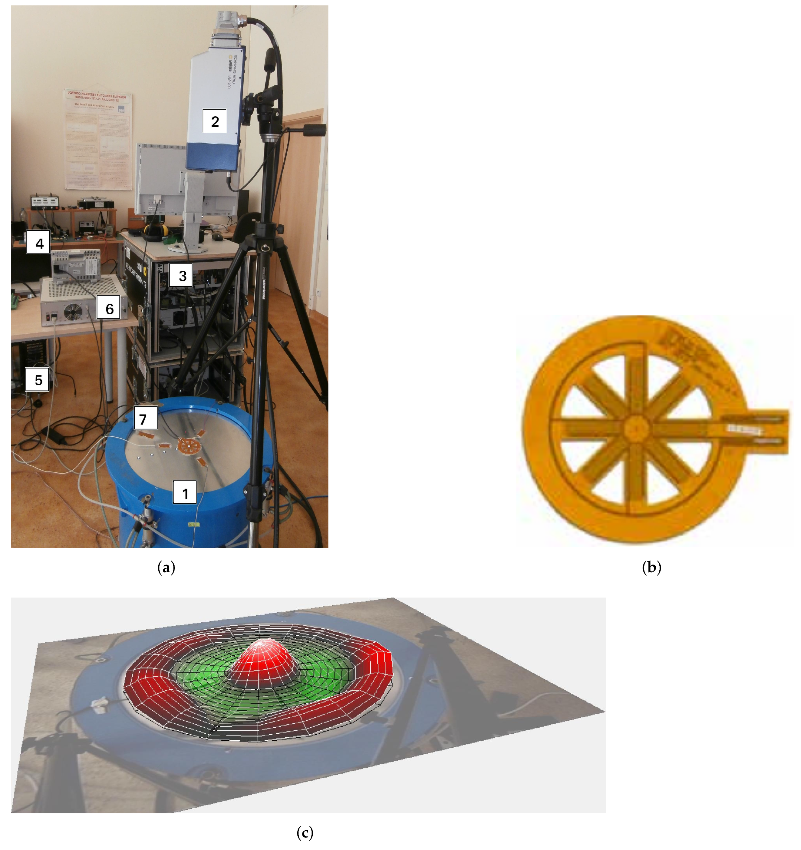
The test stand presented in Figure 1c was used in the research. The StarMFC actuator [22] was used as an executive element, powered by a high-voltage amplifier. The feedback signal for the controlle was the vibration velocity in the central point of the circular plate. The wheel plate being tested was fixed with four pneumatic cylinders. During the experiments, the source of the disc vibration was a loudspeaker placed inside a closed body that was fastened to the disc.
The parameters of the plate used in the tests are presented in the Table 1.
The MFC element used as an actuator is made of eight rectangular elements connected in a star shape, each of which works in higher elongations (2000 ppm) mode with a supply voltage in the range of 500–1500 V. The actuator is made as a monolithic element with a diameter of 40 mm. The actuator used is shown in Figure 1a. Its parameters was shown on Table 2.
A laser vibrometer was used to measure vibrations, enabling point and noncontact measurement of vibration velocity, ensuring high-precision measurements and the possibility to easily and quickly change the position of the measuring point on the surface of the tested plate. The vibrometer is equipped with a He-Ne laser with a wavelength of nm and enables speed measurement in the range of 0.01 m/s to 10 m/s from a distance of 0.4 m to over 100 m in the angular range of 20.
3. Object Identification
Adaptive control assumes the necessity to identify parameters of an unknown model in a continuous manner so that it is possible to update the parameters (settings) of the controller with the use of an adaptive algorithm. The scheme of such a system is presented in Figure 2, in which the output is a function of the object’s response to the control and the response to the system disturbance . In the case of the considered plate vibration reduction station (Figure 1), the disturbance consists of the vibrations generated from an external source as well as the measurement noise.
A stable, time invariant system presented on Figure 2 can be described by the input-output discrete-time model of the form [23]:
where t denotes discrete time: , where is the sampling period, is continuous time and d is the integer number of sampling periods contained in the time delay of the system. In this equation represents output signal, denotes the input signal and is some disturbance signal. These signals are sampled in discrete time . Using the backward shift operator this model (1) can be rewritten as:
where and are polynomials in the delay operator:
The Equation (2) can be converted to the standard linear regression notation:
where is the parameter vector
is the vector of lagged input-output data
This model describes the observed variable as an unknown linear combination of the components of the measured vector plus disturbance . To model a disturbance term for the considered object we use the structure commonly called the Auto-Regressive model with exogenous input (ARX) [23]
Using such adopted vectors and the RLS (Recursive Least Squares) algorithm, it is possible to determine the estimated parameters of the model. This leads to a recursive algorithm, the terms of which are defined by [16]
The algorithm can be improved by the use of regularization improving its stability and convergence [15,16]:
In the above expression, is the identity matrix, while , are the parameters controlling the upper and lower regularization range of the covariance matrix. During the tests, the regularization parameters were set to the values , , for which the algorithm was stable and adjusted the model parameters relatively quickly to changing conditions. The required starting conditions were taken as setting and where is a suitably large scalar value.
4. Description of Adaptive Controller
The pole placement strategy is applicable to plant models of the form of (8). We make the following assumptions:
- The orders , the delay d and the coefficients of and are known,
- and do not have any common factors.
A general form of a two-degree of freedom digital controller is given by:
where , correspond to polynomials:
Disturbances transfer function of closed system is presented below:
The characteristic equation of the expression (17) determines poles location of the closed-loop controller, which are responsible for dynamics of the control system. It is important to designing the parameters of characteristic equation ensure stable operation of the system by placing the poles inside the unit circle. The controller parameters can be calculated by solving Diophantine equations shown below.
In order to effectively solve (18) one uses the fact that the polynomial equation takes the matrix form
where is Sylvester matrix (controllability matrix), is a vector of controller parameters
and is a vector of designed characteristic equation parameters.
is a square matrix with given by [24]
where for ; for .
The vector containing the coefficients of polynomials and is obtained by inverting the matrix , which is nonsingular if and are relatively prime [24].
5. Controller Implementation and Testing
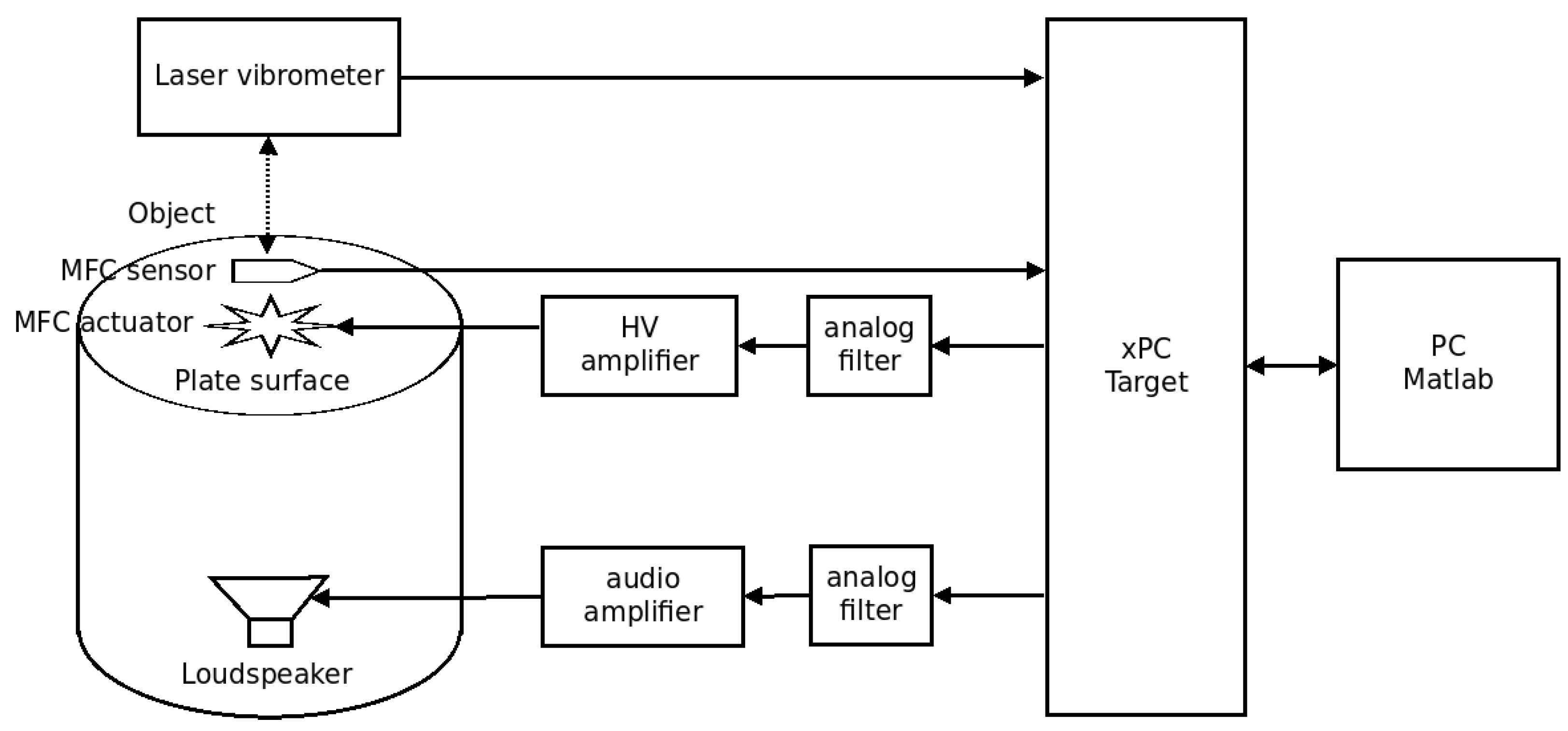
The test stand was built using a real-time control and measurement system working with the Matlab XPC Target software. The inputs of the measuring system card (PD2-MFS-8-500/14) were connected directly to MFC sensors (M-2807-P1) and the output of the laser vibrometer. The outputs of the D/A converter card (PD2-AO-8/16) were connected via an analog low-pass filter and amplifiers to actuators (speaker and star MFC). An analog filter was designed based on the Butterworth method and its cut-off frequency was 1 kHz. An analog filter was used to reproduce the output signal due to the low sampling frequency of the RT system (5 kHz). The voltage value on the actuator is related to the ranges of voltage signals generated by the DAC card (−5 V, +5 V). The structure of the implemented control system is presented in Figure 3.
An experiment was carried out to verify the effectiveness of the adaptive controller with the the poles location on the stand for active reduction of the circular plate vibrations. The time responses of the plate vibration velocity were determined experimentally with the use of a sensor placed in the central point on the plate’s surface, which coincides with the sticking point of the control actuator. The signal inducing the vibrations of the disc with the use of the loudspeaker was a chirp signal with a frequency varying from 120 Hz to 400 Hz and a sinusoidal signal with a constant amplitude and frequency of 193 Hz. During the tests, the time courses, frequency spectra and the parameters of the identified object model were compared. Tests were carried out for various model and controller structures. The results for two control structures differing in the number of coefficients of the model and the controller are presented below:
- controller 1: , , ,
- controller 2: , , , .
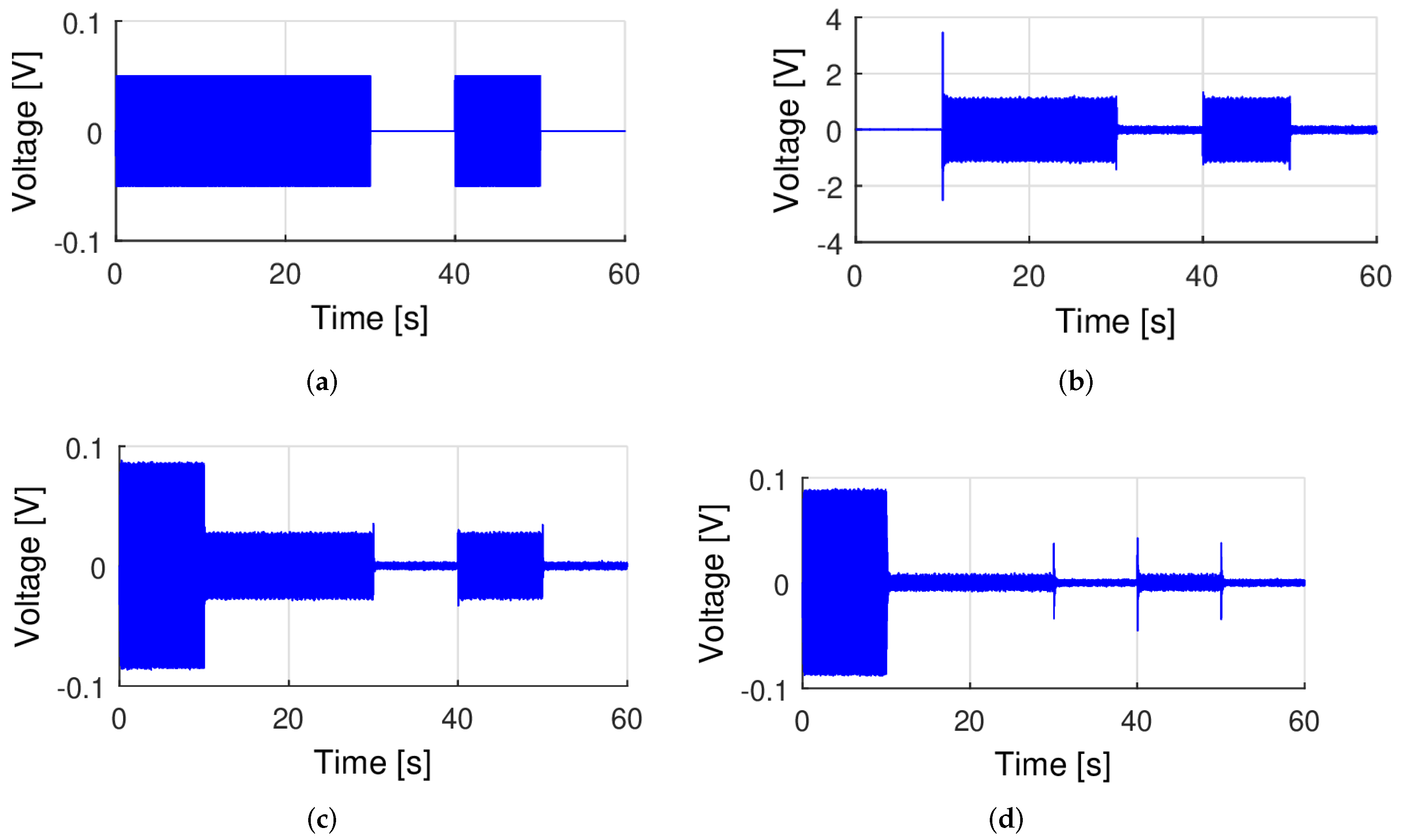
The first experiment with the applied adaptive controller was realized for both the 4th and the 6th order models with the use the sinusoidal excitation. During the tests the plate responses in time (Figure 4) and its frequency spectra (Figure 5) were compared. The results, matched to the main resonant frequency of the plate, are presented below. The excitation signal emitted by the loudspeaker was a sinusoidal waveform with a frequency of 190 Hz and an amplitude of 0.05 V. For better observation, this excitation signal was applied to the plate for 30 s, then it was turned off for 10 s, and then turned on again for 10 s (Figure 4a). The control signal from the adaptive controller was turned on 10 s after the system was started (this enables a detailed observation of its action).
It can be seen (Figure 4b) that the control signal started with a delay −10 s after the excitation signal (Figure 4a) and vibration amplitude remained almost constant for 20 s of the test when the excitation force was stopped for 10 s. If the plate was not forced to vibrate, for example, between 30–40 s, and 50–60 s, the adaptive controller produced a signal with a small, almost constant amplitude. From Figure 4c, it can be stated that plate vibrations are damped very well—the vibration amplitude of plate response in the range of 10–30 s (and also 40–50 s) decreased by more than 50%. Figure 4d shows the plate response for the same input as above, but instead of controller1, the 6th order controller 2, is turned on in the control system. This controller calculates the control signal based on a more accurate object model (nA = 6). As can be seen, a very high, about 90%, vibration reduction value was obtained in this case. This example shows that the effectiveness of adaptive feedback control increases with the increase in the accuracy of the model ( which was to be expected), moreover, it can be seen that adaptive feedback control is very effective even when the model order is not too high (nA = 6).
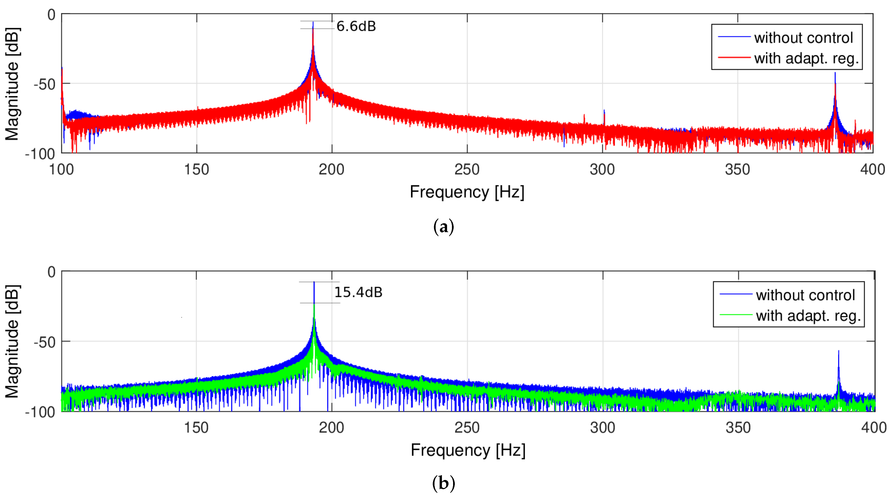
Figure 5 shows the results of the frequency analysis for the 0.1 Vpp excitation amplitude. In the case of excitation with a frequency corresponding to the object resonant frequency 193 Hz, one can see the exact vibration reduction performance of the controllers in [dB]. As can be seen from Figure 5a, controller 1 reduces the plate response amplitude by 8 dB, and controler 2—by 15 dB (Figure 5b).
To evaluate the adaptive properties of the controller, a signal with changing frequency, that is, a chirp signal, was used as plate excitation.
The interfering signal was a signal with a linearly increasing frequency from 100 to 400 Hz in a 20 s cycle and an amplitude of 0.3 Vpp. In the presented graph (Figure 6), the controller was turned on after the first cycle of the disturbing signal (t = 20 s). As can be seen, at least two dominant resonance frequencies were suppressed, and the reduction in subsequent cycles remained at a similar level.
In order to compare the obtained time waveforms more precisely, they were superimposed so that the amplitude values corresponded to the same frequencies of the disturbing signal (Figure 7), and also a FFT (Fast Fourier Transform) analysis was performed. The graph shows that two version of the considered controllers can suppress three resonant frequencies of the plate in the range from 100 Hz to 400 Hz.
Another test was performed for an analysis of the dynamics of the controller and their sensitivity to the chirp signal, with the frequency varying from 150–250 Hz, with a constant amplitude of 0.05 V and a frequency step of 2 Hz/s. The measured data were the subject of a frequency domain analysis using the FFT algorithm. The results are shown in Figure 8.
The FFT plot of the plate response to the chirp signal shows that in the case of considering adaptive control, one can expect an average of 10 dB vibration reduction in close vicinity to the resonant frequency.
Based on detailed frequency analyses, the levels of vibration reduction for individual resonance frequencies and their surroundings were determined and are summarized in Table 3.
It can be seen that the vibration reduction level for the 193 Hz resonance frequency increased from 5.5 dB for controller 1 to 9.7 dB for controller 2. In addition, the noise level in the control system was reduced. During the tests, the possibility of increasing the level of vibration reduction was limited due to the saturation of the control signal, resulting from the need to work within the linear characteristics of the MFC actuator.
Subsequent tests were performed for a sinusoidal disturbance with a frequency of 193 Hz and various amplitudes. Figure 5 shows the results of the frequency analysis for the 0.1 Vpp amplitude. In the case of excitation with a sinusoidal signal with a frequency corresponding to the resonant frequency of the object, the efficiency of the controllers is higher and amounts to 6.6 dB for controller 1 and 15.4 dB for controller 2, respectively.
Figure 9 presents how the recursively calculated parameters of the object model change in time, in response to the chirp-type excitation. As above, the colors in the chart correspond to the coefficients of the and polynomials.
6. Summary and Conclusions
The use of adaptive control in the process of vibration reduction is an interesting alternative to controllers with fixed parameters. In this paper, the approach known as the indirect adaptive pole placement method is considered. The selected algorithm belongs to the group of pole placement methods and is based on a numerical solution of the Diophantine equation. It is suitable for linear objects. In addition, it has the following advantages:
- Provides a useful physical interpretation of the dynamics of the system.
- Non-minimum phase systems can be controlled if the zeros are not canceled.
- Implementation is reasonably simple.
- Well-suited for real-time use.
- Interpreting the behavior of the close-loop system and the controller is rather easy.
- The algorithm has a neat universal polynomial form. This universal form is based on the fact that by manipulating the controller components (simple algebraic transformations), various forms of known algorithms such as PID, PI2D, and so forth can be obtained. Moreover, the algebraic equations are suitable for mathematical transformations (for grouping components) so that the result of operations compensates. Thanks to such improvements, it is possible to avoid reaching high momentary values and prevent the controller from going into saturation.
- The structure of the controller corresponds to the structure of the object—both are described by polynomials of a similar form and therefore well suited for an adaptive system—you can easily build a closed system equation.
The main purpose of the work was to examine and assess the possibility of the implementation and effectiveness of an online adaptive controller on the real-time platform included in the stand for active reduction of vibrations of a circular plate. The system model of the object was identified online with use of the Recursive Least Squares (RLS) algorithm. The use of the recursive algorithm reduces the computational effort, but the result is potentially sensitive to data perturbations. However, there were no problems with the calculation of the plate model parameters and control signals for vibration suppression during tests. In both cases—for the controller 1, controller 2 and sinusoidal excitation—a very good vibration reduction was obtained, which was more than 50% lower than the primary vibration amplitude. To evaluate the adaptive properties of the controller, a signal with changing frequency that is, a chirp signal was used as the plate excitation. Comparing the performance of controller 1 and controller 2, it can be stated that better results were achieved for the object with the controller 2, for which the object was modeled with the higher-order ARX model.
The results presented in the paper confirm the correct operation of the adaptive controller and the reduction of vibrations in a fairly wide frequency band while maintaining a relatively low order of the controller model. The identification algorithm used allowed for the correct operation of the controller and was characterized by a relatively fast convergence of model parameters as well as the maintenance of the operating point despite changes in parameters over time; however, it turns out to be sensitive to sudden changes in frequency and phase. This effect may be unfavorable, as rapid changes in object parameters could result in the instability of the model.
The effectiveness of the control depended on the optimization of the algorithms, a computer hardware, A/D and D/A measurement cards used and capabilities of the actuators. Therefore, a promising step will be to refine the RLS algorithm or replace it with an algorithm from the Affine Projection Algorithms family. The next step towards further advances in research could be to replace the equipment in use with a more efficient FPGA system.
Author Contributions
Methodology, L.L.; software, M.S.; validation, M.G., M.S. and L.L.; formal analysis, M.G. and L.L.; investigation, B.H. and M.S.; writing—original draft preparation, M.G., M.S. and L.L. All authors have read and agreed to the published version of the manuscript.
Funding
This work was partially supported by the Center for Innovation and Knowledge Transfer in Technology and Life Sciences.
Institutional Review Board Statement
Not applicable.
Informed Consent Statement
Not applicable.
Data Availability Statement
The data presented in this study are available on request: e-mail: [email protected].
Conflicts of Interest
The funders had no role in the design of the study; in the collection, analyses, or interpretation of data; in the writing of the manuscript, or in the decision to publish the results.
Abbreviations
The following abbreviations are used in this manuscript:
| ARX | AutoRegressive with eXogenous input model |
| AVC | Active Vibration Control |
| DAC | Digital to Analog Converter |
| DSP | Digital Signal Processing |
| FPGA | Field Programmable Gate Arrays |
| LQG | Linear–Quadratic Gaussian algorithm |
| LQR | Linear–Quadratic Regulator |
| MFC | Macro Fiber Composite |
| PID | Proportional–Integral–Derivative controller |
| PID–ABC | PID controller optimized by Artificial Bee Colony algorithm |
| PPF | Positive Position Feedback controller |
| FO-PPF | Fractional–Order PPF compensator |
| PSAF | Phase-Shift Adjustment controller |
| RLS | Recursive Least Squares algorithm |
References
- Fuller, C.C.; Elliott, S.J.; Nelson, P.A. Active Control of Vibration; Academic Press: Cambridge, MA, USA, 1996. [Google Scholar]
- Preumont, A. Vibration Control of Active Structures: An Introduction; Springer: Berlin/Heidelberg, Germany, 2018; Volume 246. [Google Scholar]
- Leniowska, L.; Mazan, D. MFC sensors and actuators in active vibration control of the circular plate. Arch. Acoust. 2015, 40, 257–265. [Google Scholar] [CrossRef] [Green Version]
- Leniowska, L.; Sierżęga, M. Vibration control of a circular plate using parametric controller with phase shift adjustment. Mechatronics 2019, 58, 39–46. [Google Scholar] [CrossRef]
- Leniowska, L. Modelling and vibration control of planar systems by the use of piezoelectric actuators. Arch. Acoust. 2009, 34, 507–519. [Google Scholar]
- Leniowska, L.; Kos, P. Self-tuning control with regularized RLS algorithm for vibration cancellation of a circular plate. Arch. Acoust. 2009, 34, 613–624. [Google Scholar]
- Gonçalves, J.F.; De Leon, D.M.; Perondi, E.A. Topology optimization of embedded piezoelectric actuators considering control spillover effects. J. Sound Vib. 2017, 388, 20–41. [Google Scholar] [CrossRef]
- Simonović, A.M.; Jovanović, M.M.; Lukić, N.S.; Zorić, N.D.; Stupar, S.N.; Ilić, S.S. Experimental studies on active vibration control of smart plate using a modified PID controller with optimal orientation of piezoelectric actuator. J. Vib. Control. 2016, 22, 2619–2631. [Google Scholar] [CrossRef]
- Liu, Y.; Wang, X.; Li, Y. Distributed piezoelectric actuator layout-design for active vibration control of thin-walled smart structures. Thin-Walled Struct. 2020, 147, 106530. [Google Scholar] [CrossRef]
- Pappalardo, C.M.; Guida, D. Development of a New Inertial-based Vibration Absorber for the Active Vibration Control of Flexible Structures. Eng. Lett. 2018, 26, EL_26_3_11. [Google Scholar]
- Hadi, M.S.; Darus, I.Z.M.; Tokhi, M.O.; Jamid, M.F. Active vibration control of a horizontal flexible plate structure using intelligent proportional–integral–derivative controller tuned by fuzzy logic and artificial bee colony algorithm. J. Low Freq. Noise Vib. Act. Control 2020, 39, 1159–1171. [Google Scholar] [CrossRef] [Green Version]
- Ferrari, G.; Amabili, M. Active vibration control of a sandwich plate by non-collocated positive position feedback. J. Sound Vib. 2015, 342, 44–56. [Google Scholar] [CrossRef]
- Marinangeli, L.; Alijani, F.; HosseinNia, S. A fractional-order positive position feedback compensator for active vibration control. IFAC-PapersOnLine 2017, 50, 12809–12816. [Google Scholar] [CrossRef]
- Lewis, F.L.; Vrabie, D. Reinforcement learning and adaptive dynamic programming for feedback control. IEEE Circuits Syst. Mag. 2009, 9, 32–50. [Google Scholar] [CrossRef]
- Anderson, B.D.; Bitmead, R.R.; Johnson, C.R., Jr.; Kokotovic, P.V.; Kosut, R.L.; Mareels, I.M.; Praly, L.; Riedle, B.D. Stability of Adaptive Systems: Passivity and Averaging Analysis; MIT Press: Cambridge, MA, USA, 1986. [Google Scholar]
- Praly, L. Adaptive Systems in Control and Signal Processing; Elsevier: Amsterdam, The Netherlands, 1984. [Google Scholar]
- Annaswamy, A.M.; Fradkov, A.L. A historical perspective of adaptive control and learning. In Annual Reviews in Control; Elsevier: Amsterdam, The Netherlands, 2021. [Google Scholar]
- Pu, Y.; Zhou, H.; Meng, Z. Multi-channel adaptive active vibration control of piezoelectric smart plate with online secondary path modelling using PZT patches. Mech. Syst. Signal Process. 2019, 120, 166–179. [Google Scholar] [CrossRef]
- Leniowska, L. An adaptive vibration control procedure based on symbolic solution of Diophantine equation. Arch. Acoust. 2011, 36, 901–912. [Google Scholar] [CrossRef]
- Clark, R.L.; Saunders, W.R.; Gibbs, G.P. Adaptive Structures: Dynamics and Control; Wiley: New York, NY, USA, 1998. [Google Scholar]
- González-Morphy, F. xPC Target Quick Reference Guide. MATLAB Central File Exchange. 2022. Available online: https://www.mathworks.com/matlabcentral/fileexchange/6414-xpc-target-quick-reference-guide (accessed on 18 January 2022).
- Macro Fiber Composite (MFC) Brochure. Available online: https://www.smart-material.com/media/Datasheets/MFC_V2.4-datasheet-web.pdf (accessed on 18 January 2022).
- Ljung, L. System Identification: Theory for the Users; Prentice Hall: Hoboken, NJ, USA, 1999. [Google Scholar]
- Landau, I.D.; Lozano, R.; M’Saad, M.; Karimi, A. Adaptive Control: Algorithms, Analysis and Applications; Springer Science & Business Media: Berlin/Heidelberg, Germany, 2011. [Google Scholar]
Figure 1.
Test stand and MFC actuator. (a) Test stand, 1—the object with MFC actuator, 2—a laser head, 3—a vibrometer, 4—PC, 5—computer with real time system and data acquisition cards, 6—high voltage amplifier 7—MFS sensor; (b) The Star MFC; (c) Illustration of the vibration mode of the plate at 193 Hz.

Figure 2.
Arrangement of system identification in an adaptive control system for the object described by ARX model.
Figure 2.
Arrangement of system identification in an adaptive control system for the object described by ARX model.

Figure 3.
Test stand realization and connection scheme.

Figure 4.
Example test of an adaptive controller for the sinusoidal disturbance of 190 Hz. (a) Excitation signal; (b) Controller output; (c) Plate response with the use of controller 1; (d) Plate response with the use of controller 2.
Figure 4.
Example test of an adaptive controller for the sinusoidal disturbance of 190 Hz. (a) Excitation signal; (b) Controller output; (c) Plate response with the use of controller 1; (d) Plate response with the use of controller 2.

Figure 5.
FFT analysis for two kinds of the adaptive controllers in case of the sinusoidal excitation. (a) Controller 1; (b) Controller 2.
Figure 5.
FFT analysis for two kinds of the adaptive controllers in case of the sinusoidal excitation. (a) Controller 1; (b) Controller 2.

Figure 6.
Time response of the system for a chirp excitation without control (0–20 s) and with the adaptive controller No.1 (20–40 s). (a) Plate response; (b) Control signal.
Figure 6.
Time response of the system for a chirp excitation without control (0–20 s) and with the adaptive controller No.1 (20–40 s). (a) Plate response; (b) Control signal.

Figure 7.
Time and frequency responses for a system with the adaptive controllers to a chirp disturbance signal. (a) Time responses with controller 1; (b) Frequency responses with controller 1; (c) Time responses with controller 2; (d) Frequency responses with controller 2.
Figure 7.
Time and frequency responses for a system with the adaptive controllers to a chirp disturbance signal. (a) Time responses with controller 1; (b) Frequency responses with controller 1; (c) Time responses with controller 2; (d) Frequency responses with controller 2.


Figure 8.
FFT plate responses to the chirp excitation of 150–200 Hz without control (blue plot) and with the adaptive controller (green and red plot). (a) Controller 1; (b) Controller 2.
Figure 8.
FFT plate responses to the chirp excitation of 150–200 Hz without control (blue plot) and with the adaptive controller (green and red plot). (a) Controller 1; (b) Controller 2.

Figure 9.
Graph of changes in the parameters of polynomials: (a) and (b) .


Table 1.
Material parameters of the plate model.
| Property | Symbol | Value [Unit] |
|---|---|---|
| Radius of the plate | a | 0.237 [m] |
| Thickness of the plate | h | 0.0318 [m] |
| Density of the plate | 2700 [kg/m3] | |
| Young’s Module | E | 71 [GPa] |
| Poison ratio | v | 0.3 |
Table 2.
The parameters of MFC actuator.
| Property | Value [Unit] |
|---|---|
| type | 8-star |
| Tensile modulus, rod direction | 30.336 [GPa] |
| Tensile modulus, electrode direction | 15.857 [GPa] |
| Poisson’s ratio | 0.31 |
| Thickness | 0.3 [mm] |
| Diameter | 40 [mm] |
Table 3.
Summary of vibration reduction levels for various frequencies.
| f [Hz] | 124 | 176 | 181 | 190 | 193 | 195 | 328 |
|---|---|---|---|---|---|---|---|
| Adaptive Controller 1 | 0.7 dB | 1.9 dB | 1.8 dB | 3 dB | 5.5 dB | 3 dB | 3.8 dB |
| Adaptive Controller 2 | 1.5 dB | 3.2 dB | 3.7 dB | 4.1 dB | 9.7 dB | 3.2 dB | 7.5 dB |
Publisher’s Note: MDPI stays neutral with regard to jurisdictional claims in published maps and institutional affiliations. |
© 2022 by the authors. Licensee MDPI, Basel, Switzerland. This article is an open access article distributed under the terms and conditions of the Creative Commons Attribution (CC BY) license (https://creativecommons.org/licenses/by/4.0/).
Share and Cite
MDPI and ACS Style
Leniowska, L.; Grochowina, M.; Sierżęga, M.; Hołota, B. An Adaptive Method for Reducing Vibrations of Circular Plates with Recursive Identification. Appl. Sci. 2022, 12, 2723. https://0-doi-org.brum.beds.ac.uk/10.3390/app12052723
AMA Style
Leniowska L, Grochowina M, Sierżęga M, Hołota B. An Adaptive Method for Reducing Vibrations of Circular Plates with Recursive Identification. Applied Sciences. 2022; 12(5):2723. https://0-doi-org.brum.beds.ac.uk/10.3390/app12052723
Chicago/Turabian StyleLeniowska, Lucyna, Marcin Grochowina, Mariusz Sierżęga, and Bogumił Hołota. 2022. "An Adaptive Method for Reducing Vibrations of Circular Plates with Recursive Identification" Applied Sciences 12, no. 5: 2723. https://0-doi-org.brum.beds.ac.uk/10.3390/app12052723
Note that from the first issue of 2016, this journal uses article numbers instead of page numbers. See further details here.