
Phase Shifting Enhancement of a Substrate-Integrated Waveguide Phase Shifter Based on Liquid Crystal

Department of Electrical Electronics Engineering, Laboratory of Wave-Arrays and Display Engineering (WADE Group), Pohang University of Science and Technology (POSTECH), Pohang 37673, Gyeongbuk, Republic of Korea
*
Author to whom correspondence should be addressed.
†
These authors contributed equally to this work.
Appl. Sci. 2023, 13(4), 2504; https://0-doi-org.brum.beds.ac.uk/10.3390/app13042504
Submission received: 9 January 2023
/
Revised: 8 February 2023
/
Accepted: 14 February 2023
/
Published: 15 February 2023
(This article belongs to the Special Issue Liquid Crystal Thin Films: Structures and Applications)
Abstract
:A novel technique to enhance the phase shifting range of a liquid crystal (LC)-based, substrate-integrated waveguide (SIW) phase shifter by inserting inductive posts (IPs) is presented for the first time. The IPs inserted in the LC-based SIW phase shifter produce a phase advance based on the relative permittivity of the LC, resulting in an additional differential phase shift. At 28 GHz, the proposed structure with IPs achieves a ratio of maximum differential phase shift () to maximum insertion loss (FoM1) = 52.82 and ratio of maximum differential phase shift to length (FoM2) = 2.62 . Compared with conventional LC-based SIW phase shifters that lack an IP and use the same amount of LC, the FoM1 increased by 16% and the FoM2 increased by 55%. In addition, compared to the typical structure that uses additional LCs instead of IPs, the FoM1 decreased by 7%, and FoM2 increased by 21%. Therefore, inserting IPs into the LC-based SIW phase shifter can reduce the dimensions of the phase shifter and the amount of LCs required to achieve the desired differential phase shift. We believe this work can contribute to the design of compact and efficient SIW phase shifters for future telecommunication systems.
1. Introduction
Liquid crystals (LCs) are well-known materials in the liquid crystal display (LCD) industry because of their dielectric anisotropic and birefringence nature that permits the tunability of their optical properties. This anisotropic characteristic also can be a promising candidate for use in microwave engineering because of its versatility at high frequency ranges. The tunability of LCs is not only favorable in photonics applications but also for radio frequency band (RF; 3 kHz–300 GHz) applications, especially for reconfigurable millimeter-wave systems (mmWave; 30 GHz–300 GHz). By changing the dielectric characteristic of the LC layer from which a wave is propagating, we can change the propagation constant (specifically, the phase constant ) of that wave. Because of this tunability of LCs, we can implement various microwave devices. The phase shifter is a key component of phased array antennae that are used to implement beam steering in communication systems such as mobile devices [1] and automotive radar [2]. For the implementation of beamforming networks that operate in the millimeter-wave (mmWave) range, phase shifters with high tuning efficiency, low-loss, small size, and low cost have been studied [3,4]. For example, variable phase shifters that use CMOS [5] or micro-electromechanical systems (MEMS) [6] have been proposed, but they suffer from significant losses and inadequate operational stability in the mmWave range [7].
LCs offer an alternative approach for implementing tunable phase shifters [8,9]. LCs have dielectric anisotropy controlled by static electric or magnetic fields. In addition, they have relatively low loss characteristics at high frequencies, especially above 10 GHz [10], so they have been usefully used to implement a variable phase shifter at the mmWave range. Tunable phase shifters using LCs can be implemented using planar transmission lines such as microstrip lines (MS line) and coplanar waveguides (CPW) [11,12], metallic waveguides, and substrate-integrated waveguides (SIW) [13]. MS lines and CPW phase shifters are commonly used to implement liquid crystal phase shifters in microwave and millimeter-wave applications. However, this configuration suffers from some drawbacks for using high-frequency range applications. The first drawback is the severe dispersion of these planar transmission line topologies, which can cause the phase shift of the transmitted signal to vary with frequency. This can make it difficult to achieve a uniform phase shift over a wide frequency range. The second drawback is the fabricating difficulty at high frequency ranges. Fabricating CPW and MS lines can be challenging, particularly at high frequencies where the dimensions of the components become very small. This can increase the cost and complexity of manufacturing liquid crystal phase shifters using these types of transmission lines. In addition, the limited cell gap range for implementation, caused by impedance matching issues, and unwanted coupling with other components that negatively impact the performance of the phase shifter are key drawbacks of the planar transmission line topology [12].
SIW can be a promising alternative structure for these drawbacks. SIW combines the advantages of planar technologies and conventional metallic waveguides to demonstrate compactness, high-quality factors, wide bandwidth, lower loss, and high-power handling capabilities. The most important advantage of SIW technology is the ability to integrate multiple devices on a single substrate, reducing losses and parasitics [14]. Therefore, LC-based SIW phase shifters are a good candidate for mmWave phase shifters [15,16]. Research on the existing LC-based SIW phase shifter has been focused on designing to change the effective relative permittivity of the LC sealed in the cavity. In this case, the phase shifter length should be extended to increase the differential phase shift. However, phase shifters are subject to strict size constraints in arrays where individual antenna elements must be integrated with phase shifters. [17,18].
Therefore, we propose a novel approach to improve the phase shifting range of LC-based SIW phase shifters by incorporating inductive posts (IPs) without expanding the device’s dimensions. The IPs induce a phase advance that is proportional to the relative permittivity of the substrate () [19], resulting in an enhanced differential phase shift (ϕ). To validate this concept, we designed and compared structures with and without IPs, and our simulation results demonstrate that the insertion of IPs leads to a greater differential phase shift compared to LC-based SIW phase shifters that rely on additional LCs. Hence, we believe that the integration of IPs can enhance the phase shifting range while maintaining a compact and cost-effective design, making it a promising solution for future telecommunication systems.
2. Fundamentals of Liquid Crystals for Microwave Applications
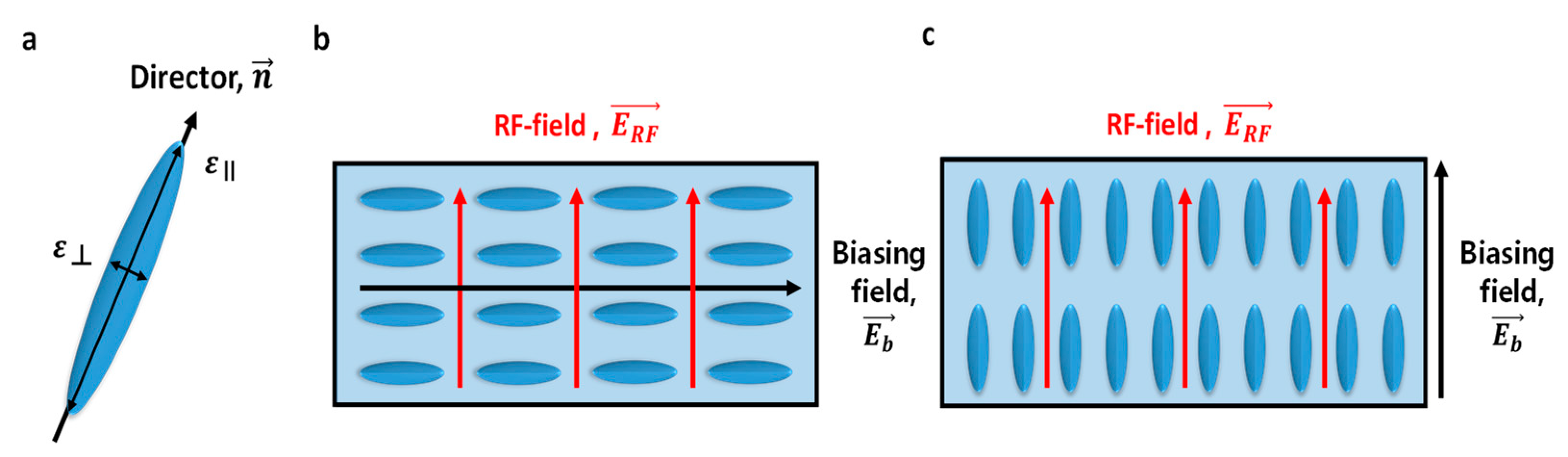
An LC is a mesophase between isotropic liquids and crystalline solids. LC molecules are shaped like rods or disks, which tend to align in a certain direction, which is described by the time-averaged direction along the long axis of the LC molecule (Figure 1a) [20]. LCs are dielectric materials with anisotropic characteristics such as the relative dielectric anisotropy and dielectric loss tangent . The relative dielectric anisotropy can be defined as:
where is the LC’s effective parallel relative permittivity and is LC’s effective perpendicular relative permittivity.
The relative permittivity of LC depends on the angle between the director and the radio frequency (RF) field [10,21]. By regulating the LC directors by external bias, we can change the effective dielectric constant of the structure continuously. When the RF field is perpendicular to the LC director, the RF field experiences a complex that corresponds to the short axis of the LC (Figure 1b). In contrast, when the RF field is parallel to the LC director, the RF field experiences the complex that corresponds to the long axis of the LC (Figure 1c). Between these, relative LC permittivities can be obtained continuously by changing using the external field. This external field-controlled tuning of the relative permittivity with a maximum effective anisotropy can be used directly for continuous phase shifting [22]. The maximum differential phase shift of the LC phase shifter can be written as:
where is effective value of the whole RF device, is the effective value of the whole RF device, is the effective anisotropy of the refraction index, is the frequency of operation, L is the physical length of the phase shifter, and is the speed of the light. The LC used in this study is ZOC-A001XX from the JNC corporation; at 28 GHz, it has = 2.47, = 3.09, tan δ⊥ = 0.015, and tan δ = 0.004.
3. Inductive Posts in the LC-Based SIW Phase Shifter
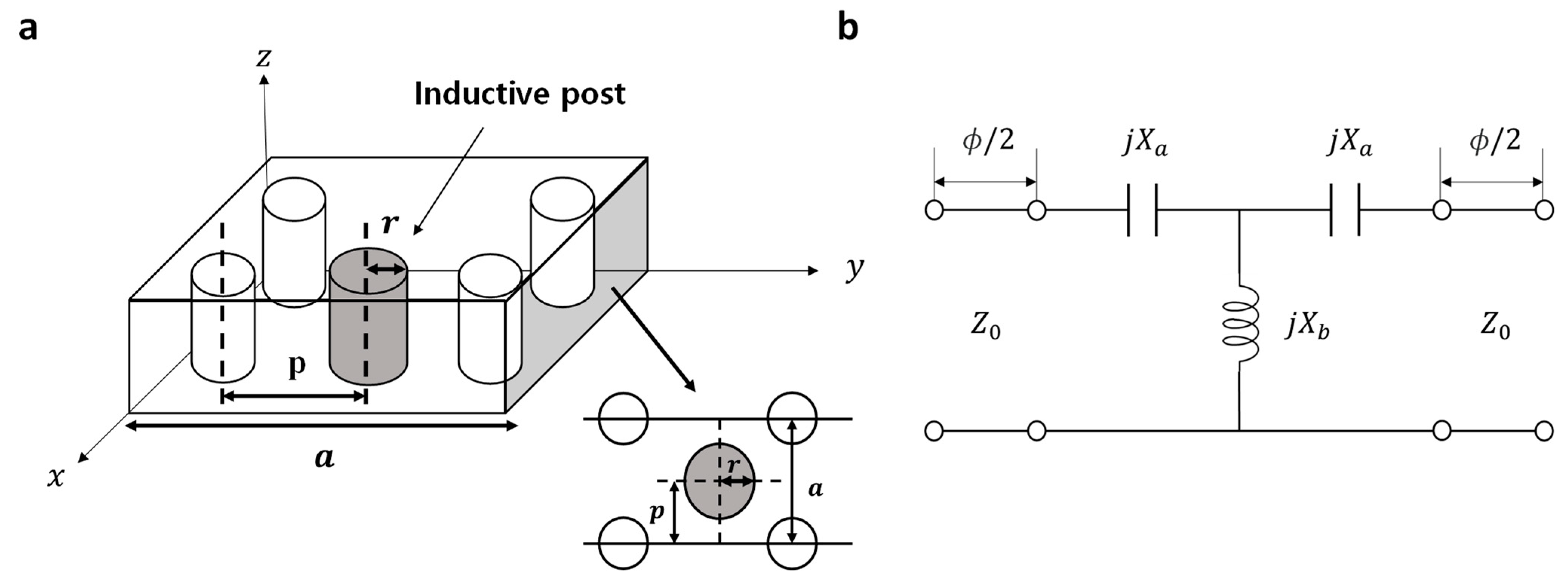
The cylindrical IP inserted into the SIW (Figure 2) is equivalent to a T-network high-pass filter [23]. The high-pass filter produces a phase advance when used in a phase shifter and is widely used in SIW phase shifters [24,25]. The phase advance ϕ can be calculated as [19]:
where is the reactance, is the susceptance, and is the line’s characteristic impedance. To gain a deeper understanding of parameters related to phase modulation, we need the following detailed equations [19]:
where a is the width of the waveguide, is the guide wavelength, r is the radius, and p is the offset of the inductive posts in the waveguide (Figure 2). and are functions of radius and offset of the IP (Figure 2). is the relative dielectric constant of the substrate [14]. From the equations, the phase advance caused by the insertion of inductive posts depends on their r and p and the substrate’s permittivity . ϕ increases as r and p increase, but decreases as increases [23]. We inserted an IP into the LC-based SIW phase shifter that makes a phase advance depending on . The LC-based SIW phase shifter with IPs produces the following phase shift as
where is the resultant phase shift of phase shifter, is the electrical length of the phase shift, and is the propagation constants. Therefore, the differential phase shift of the LC-based SIW phase shifter with inductive posts inserted can be written as
is the phase advance produced by the IP when the LCs are perpendicular to the RF field, and is produced by the IP when the LCs are parallel to the RF field. The inserted IP produces a greater ϕ when the LCs are perpendicular to the RF field than when they are parallel. This phenomenon results in a difference in ϕ and, thereby, an increased Δϕ. In this work, we propose the effectiveness of inserting IPs for phase advance at LC-based SIW phase shifter.
4. LC-Based SIW Phase Shifter Design
4.1. Structure
We designed the LC-based SIW phase shifter with IPs that operate at 28 GHz. Inserting the IPs increases the cut-off frequency by reducing the effective width of the SIW, so the SIW before the insertion of the IPs was designed to have a cut-off frequency of 15 GHz with a large enough margin. The 15 GHz cut-off frequency means that we can send our signal to another port entirely with phase changing while propagating.
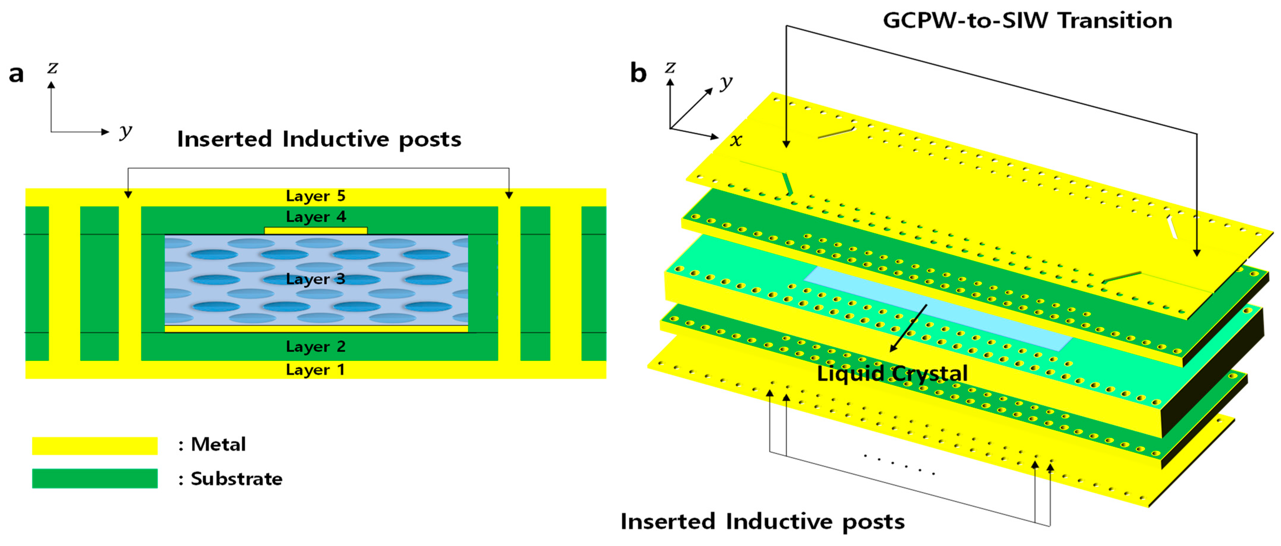
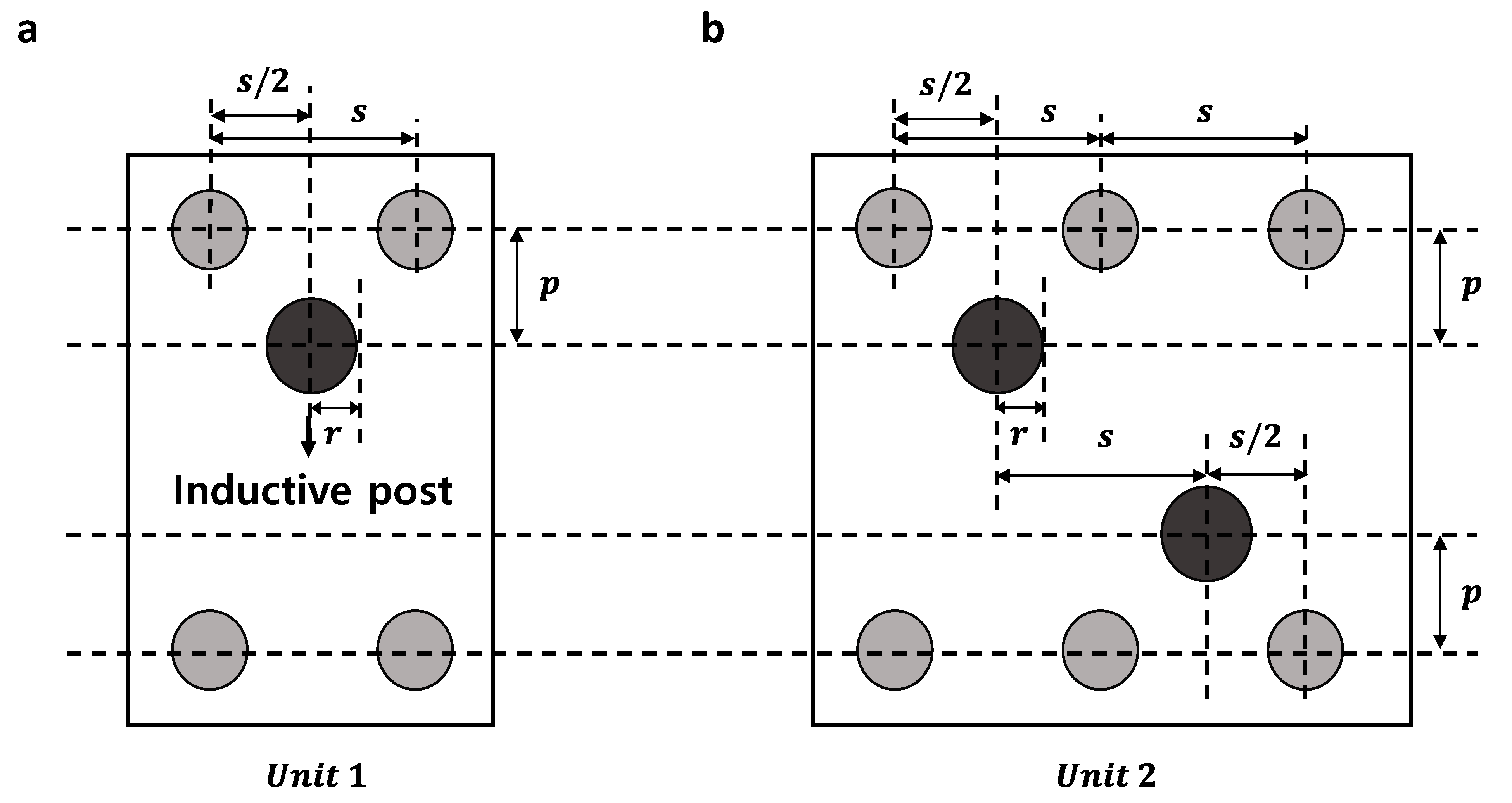
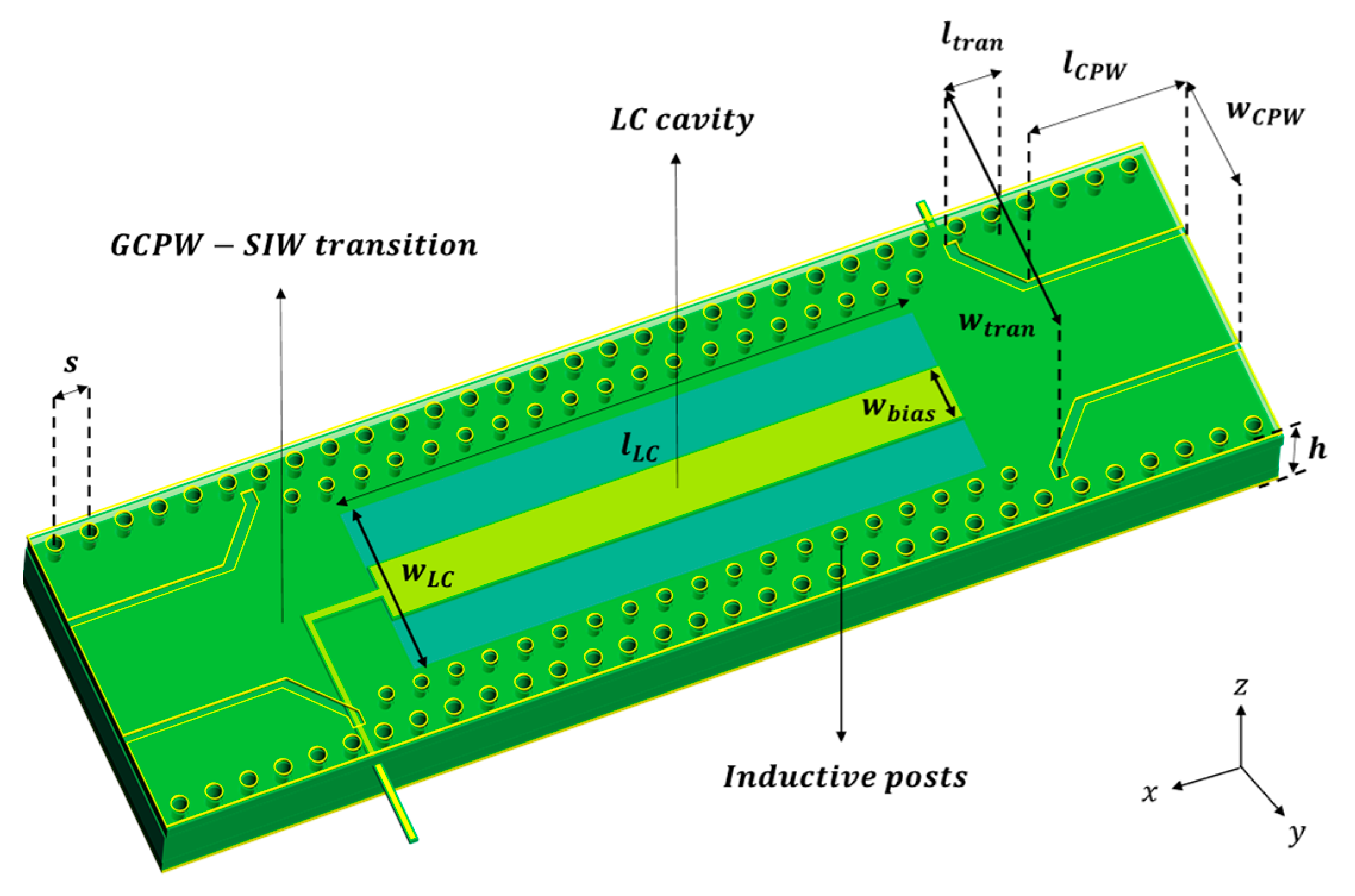
The proposed LC-based SIW phase shifter consists of five layers (Figure 3). Layers 1 and 5 are respectively the upper and lower metal planes of the SIW and are electrically connected through the metalized holes. The metal planes are copper and are 7 μm thick. Layers 2, 3 and 4 are composed of Roger 4003C ( = 3.38, = 0.0021) as dielectric substrates. Designed thicknesses were 0.1 mm for layers 2 and 4 and 0.5 mm for layer 3. The LC was set inside a cavity (3.5 mm × 10 mm, 0.5 mm high) in layer 3. The transition from grounded coplanar waveguide (GCPW) to SIW occurs at the end of the phase shifter for the integration applications of SIW [26,27]. The GCPW was designed to have an impedance of 50 Ω [28,29]. Then, IPs with a radius r = 0.1 mm were placed with offset p = 0.9 mm to increase Δϕ. The dimensions of and were chosen to optimize the trade-off between the insertion loss and the Δϕ that the posts induce. The IPs were located in the middle of the metalized holes of the SIW and continuously arranged at intervals , as shown in Figure 4.
4.2. Biasing System
Various biasing systems have been proposed to change the relative permittivity of an SIW structure with LC driving [16,30]. We used microstrip lines [31] as the biasing structure for verifying the LC director’s driving in the proposed SIW structure. The microstrip conductors were set in copper that was 0.5 mm wide and 1 μm thick.
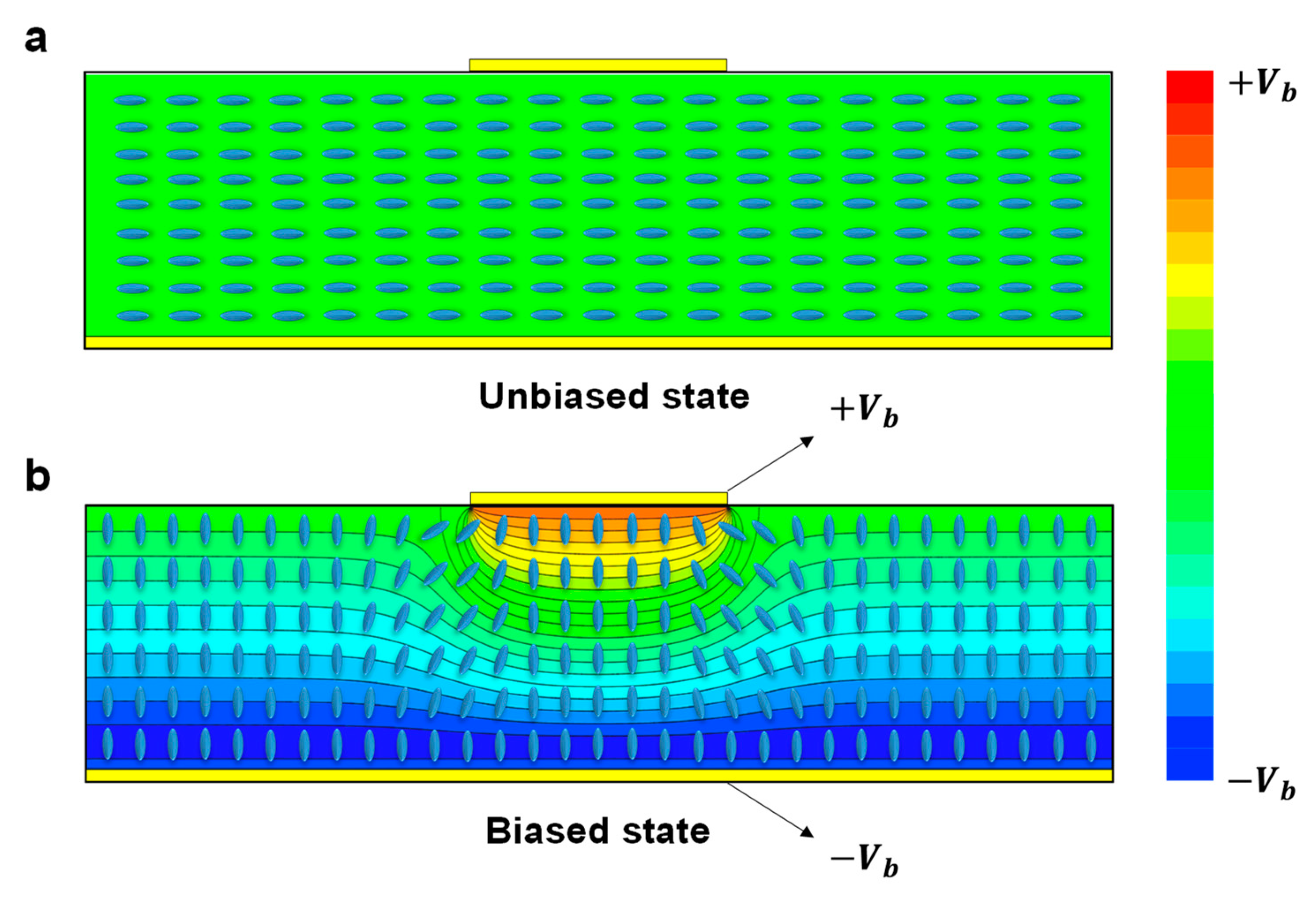
We checked the changes in the LC state by using an LC simulator (TechWiz LCD) [32,33]. Simulations were conducted using ANSYS HFSS for RF simulation, and TechWiz for LC director alignment. Before voltage was applied to the biasing structure, LCs were in a perpendicular state (Figure 5a), and after a bias voltage = 70 V was applied, the LCs were in a parallel state (Figure 5b). This change demonstrates that this biasing process drove the LC molecules between its extreme states. Furthermore, the RF field that propagated in TE10 mode was verified. Therefore, in simulations, we can assume that the LC layer is an isotropic material with relative permittivities and [34,35]. The SIW phase shifter using LC with a microstrip biasing line is depicted in Figure 6.
5. Results and Discussion
5.1. Phase Advance by IP
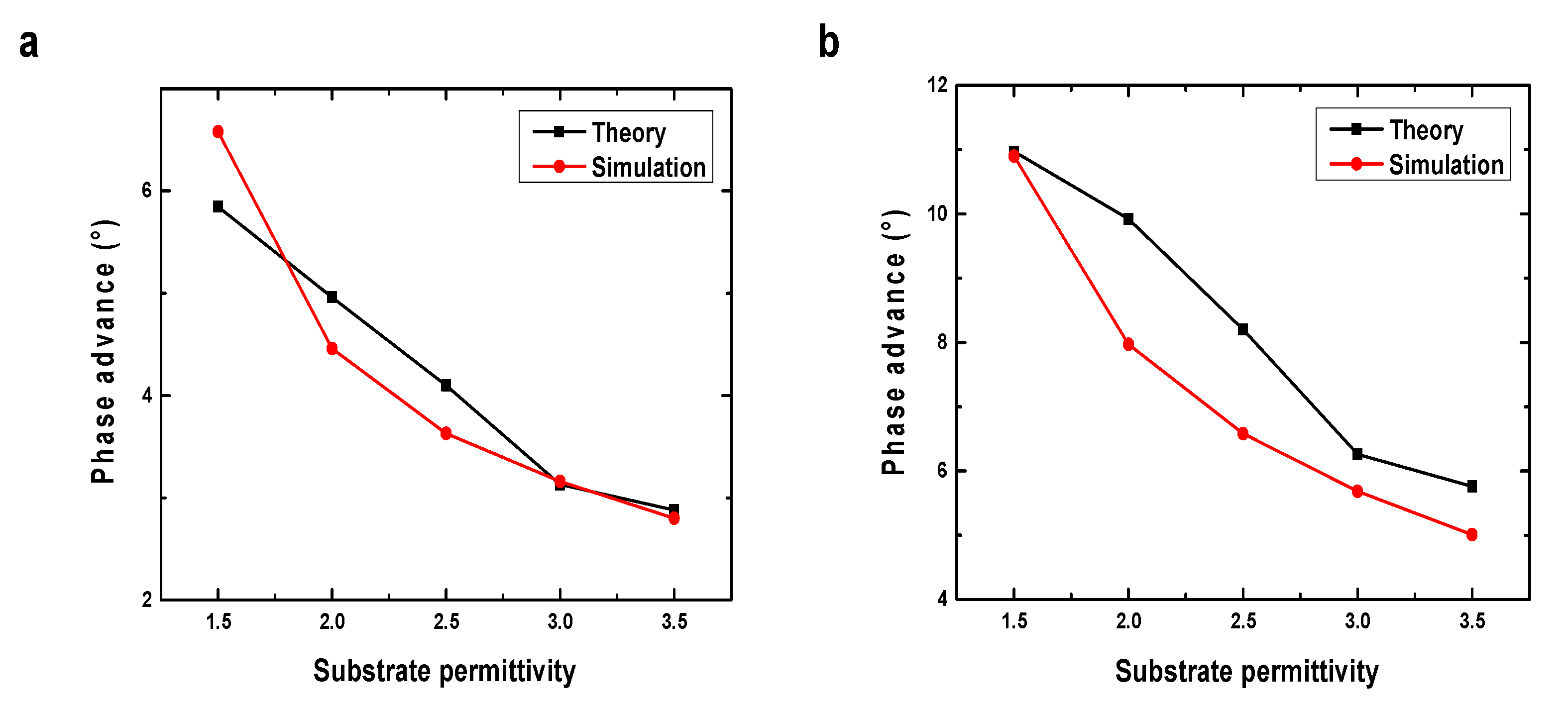
We verified the phase-advance tendency of IPs as a function of by using a 3-D electromagnetic (EM) simulation tool (HFSS). The simulation was run using SIW structures by regulating the number of IPs, 1 (Figure 4a) and 2 (Figure 4b), at 28 GHz; was varied from 1.5 to 3.5, with = 0.1 mm and p = 0.5 mm, respectively. The phase advance decreased as increased, as depicted in Figure 7. As we showed with Equations (3)–(9), it is remarkable that even though the permittivity increased, the phase advance term rather showed a tendency to decrease, which showed a tendency to coincide with the formula. The slight discrepancy between theoretical calculations and simulation results could be due to the use of equivalent circuit assumptions for the T-network high-pass filter. Nonetheless, we have confirmed that the trend of our simulation results is consistent with the calculated results, demonstrating the effectiveness of the LC-based SIW concept of utilizing inductive posts for phase shifting.
5.2. Enhanced Phase Shifting Range by Inserting IPs
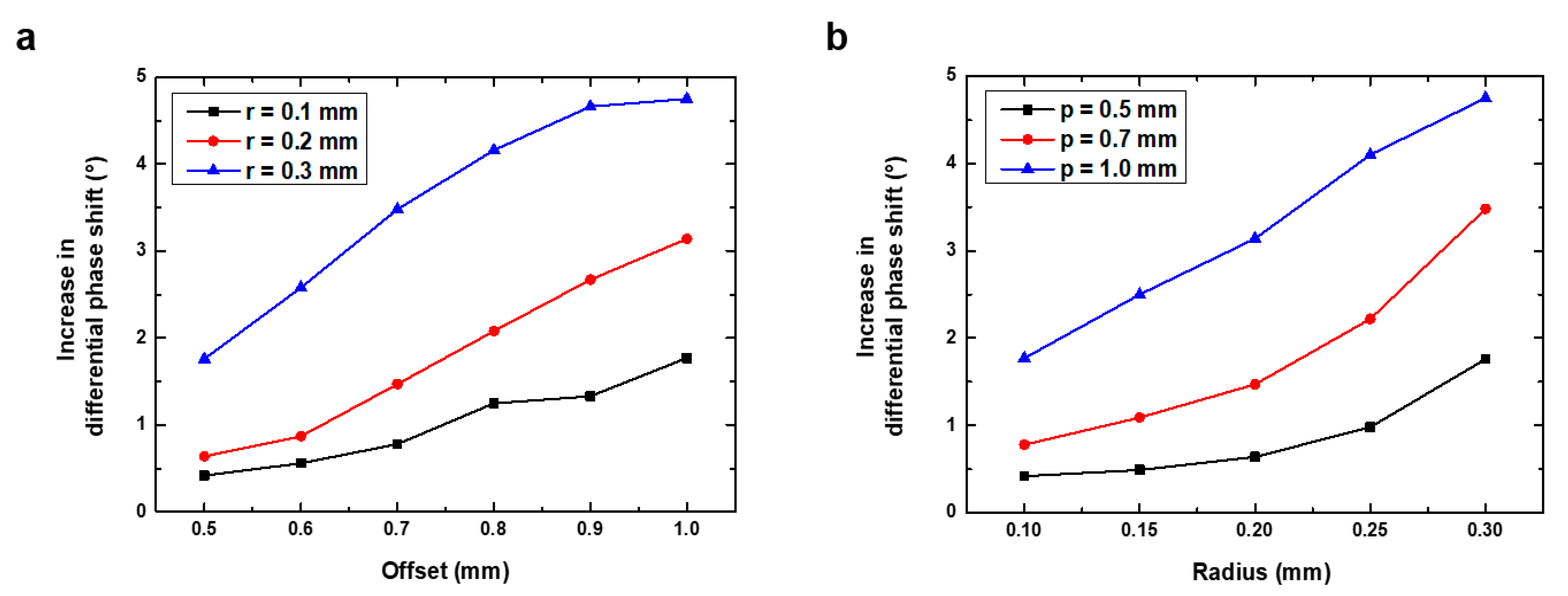
We used the designed structure (Figure 4a) to verify the increase in Δϕ by the IPs at 28 GHz. The Δϕ was obtained by using the perpendicular and parallel relative permittivity of ZOC-A001XX by considering the angle between the RF field and LC directors. As a result, we found that inserting the IPs effectively increased Δϕ, as we discussed in the Section 3. To evaluate the tendency among parameters, we regulated the parameters of r and p. When r is fixed, Δϕ increased as p increased (Figure 8a). In addition, when p was fixed, the Δϕ increased as r increased (Figure 8b). Therefore, inserting an IP can increase Δϕ, and the desired Δϕ can be obtained by changing the r or p, or both, of the IP.
5.3. LC-Based SIW Phase Shifter
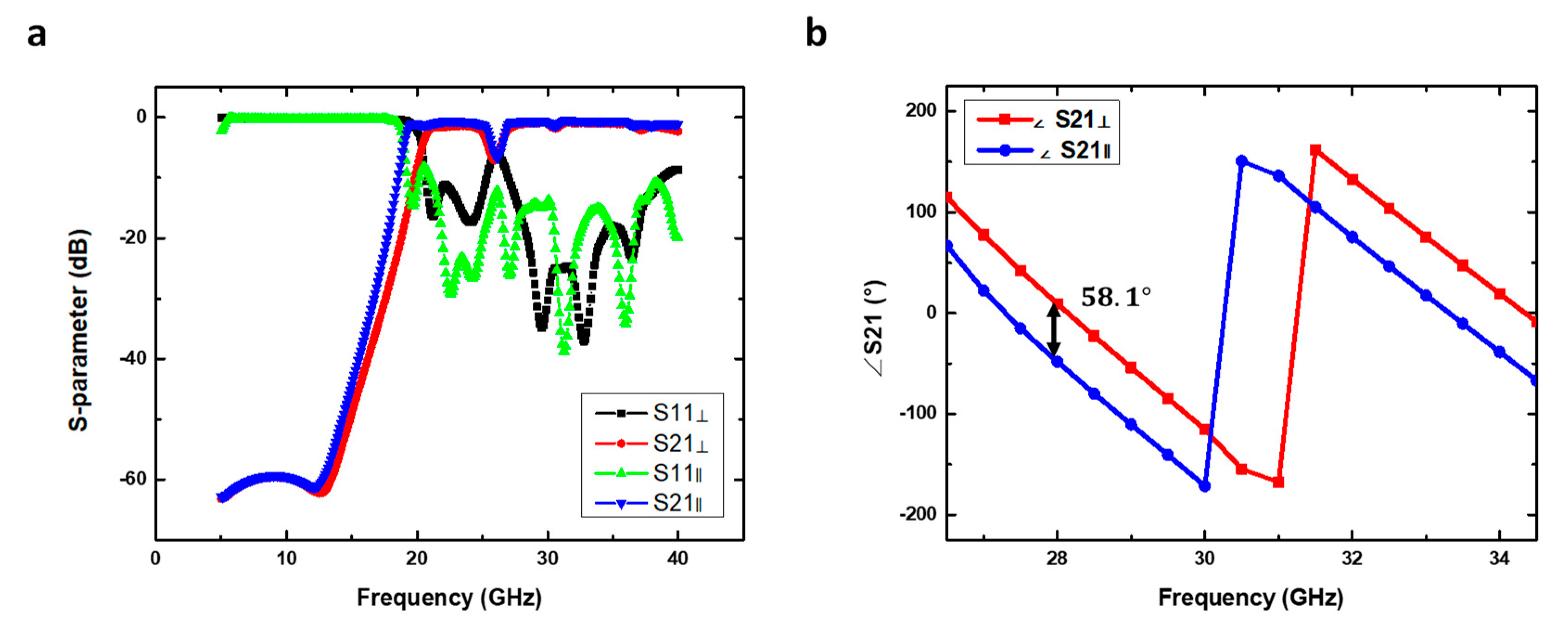
The proposed LC-based SIW phase shifter was simulated with HFSS at the operating frequency of 28 GHz. The addition of IPs increased the cut-off frequency from 15 GHz to 20 GHz (Figure 9a). Because our target operating frequency is 28 GHz, our design has a large enough margin. S-parameters of the proposed structure showed insertion loss IL = 1.1 dB, and Δϕ = 58.1° (Figure 9b). The comparison of the proposed structure, Case1, and Case 2 are presented to evaluate the effectiveness of our proposed structure in Table 1. The proposed structure had , which was 55.68% higher than in Case 1 and 21.85% higher than in Case 2, and an IL about 35% higher than in both Case 1 and 2.
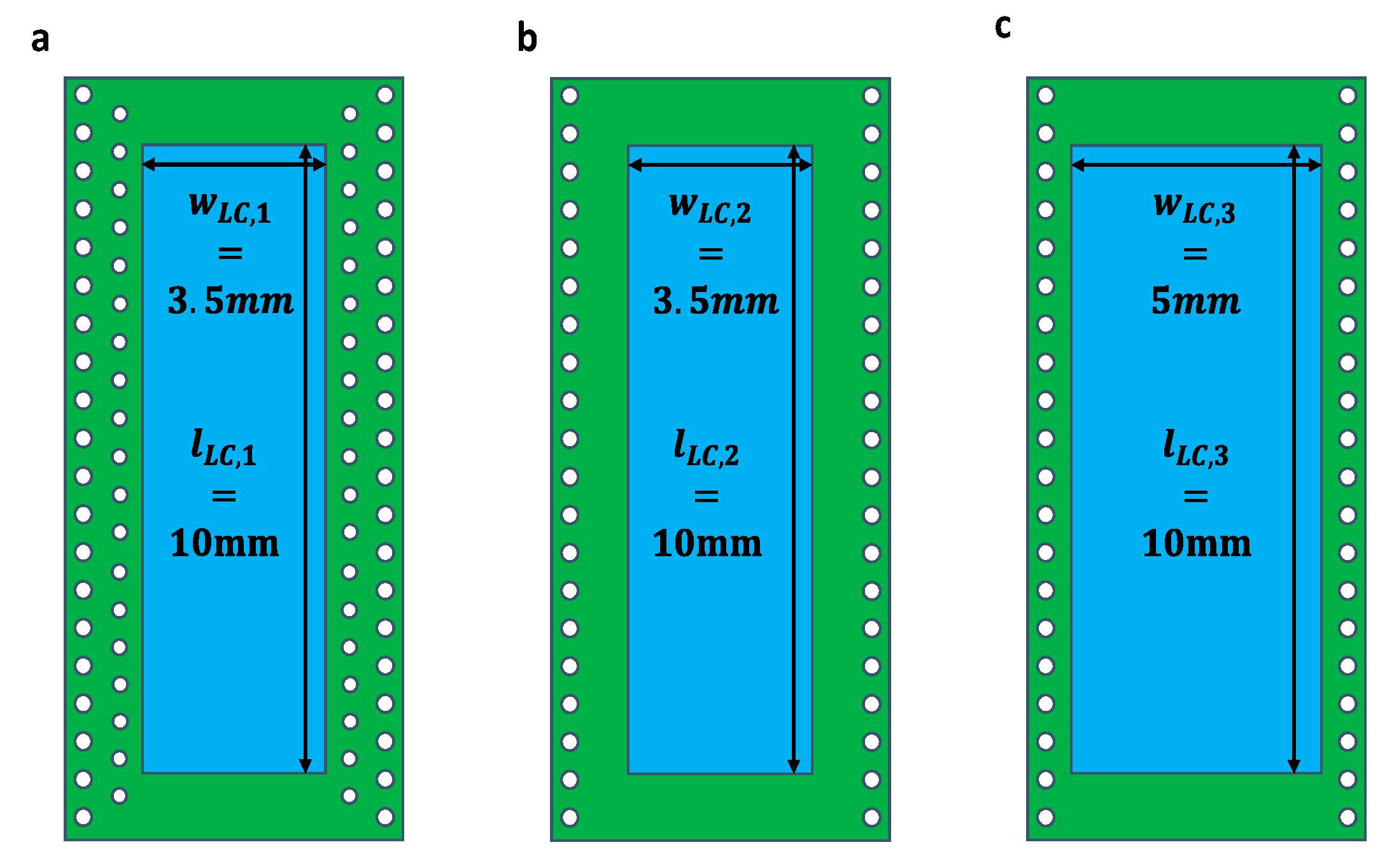
To verify the effect of Δϕ caused by the additional IPs, we designed two conventional structures: Case 1, which uses the same amount of LC as the suggested structure, and Case2, which uses additional LCs instead of IPs (Figure 10). Their electrical characteristics were compared using two figures of merit (FoM). The figure of merit 1 (FoM1; °/dB) for a passive phase shifter is defined as
This factor is important because it is related to the price competitiveness of LC devices. In order to secure price competitiveness in an array structure with numerous unit cells, the amount of LC used for driving in a single cell must be minimized. The proposed LC-based phase shifter’s FoM1 was 52.82 °/dB, which is 16.06% larger than Case 1 and 6.94% lower than Case 2. These changes are caused by the additional IP that simultaneously increases Δϕ and IL. FoM2 (°/mm) is per length, which is important when determining the required dimension of the phase shifter to achieve the desired Δϕ [36,37]:
By this parameter, we can evaluate the footprint of the LC devices. Research related to the miniaturization of RF structures has been a subject of much interest. The suggested LC-based SIW phase shifter has FoM2 = 2.62 °/mm, which is 55.03% higher than Case 1 and 21.3% higher than Case 2. The proposed IP-inserted LC-based SIW phase shifter increased FoM2 with fewer LCs than the existing structure. The phase shift results in Case 1 and Case 2 differ due to the varying LC volumes in their design. The RF signal passes through the space between the posts, and the volume of LCs it travels through determines the tunability of the LC-based SIW design. Case 2 has a larger LC area, leading to a larger tunable range of the effective dielectric constant of the entire SIW phase shifter compared to Case 1. As a result, the Figure of Merit (FoM2) in Case 2 is better than in Case 1. In conclusion, we confirmed that inserting Ips into the LC-based SIW phase shifter can enhance phase shifting effectively, even using a smaller amount of LCs or smaller dimensions of the phase shifter (Table 2 and Table 3).
6. Conclusions
This paper has presented a novel method to increase Δϕ by inserting IPs into an LC-based SIW phase for the first time. Inserted IPs increase Δϕ by generating different phase advances based on the of the LC. Furthermore, the amount of Δϕ increase can be adjusted by manipulating the r and p of the IPs.
Simulation results at an operating frequency of 28 GHz showed Δϕ = 58.1° and IL = 1.1 dB, with FoM1 (ratio of maximum and the insertion loss) = 52.82 °/dB and FoM2 ( per length) = 2.62 °/mm. Compared with the conventional LC-based SIW phase shifter that uses the same amount of LC, FoM1 increased by 16.06% and FoM2 increased by 55.03%. In addition, compared to the conventional, LC-based SIW phase shifter, which uses additional LC instead of IP insertion, FoM1 was reduced by 6.94%, and FoM2 was increased by 21.3%. The proposed design with additional IPs has a higher Δϕ per length than the conventional structure that uses additional LCs instead of IPs.
Inserting inductive posts can enhance the phase shifting range without increasing the dimension or the amount of LCs of the LC-based SIW phase shifter. Therefore, the proposed design can reduce the size of the phase shifter or the amount of LCs required to achieve the desired differential phase shift. We believe this work will contribute to developing a compact and cost-effective LC-based SIW phase shifter for building future telecommunication systems. However, further studies, including parameter studies and investigations into dispersion characterization and implementation with regards to the LC filling process, are necessary to reach the commercialization level of LC-based SIW structures.
Author Contributions
Conceptualization, H.-J.S. and J.-Y.C.; Validation, J.-S.M.; Formal analysis, H.-J.S., J.-S.M. and J.-Y.C.; Writing—original draft, H.-J.S. and J.-S.M.; Writing—review & editing, J.-S.M.; Project administration, W.-S.K. All authors have read and agreed to the published version of the manuscript.
Funding
This work was supported by Nepes in South Korea, and the liquid crystal ZOC-A001 was supplied from JNC Corporation in Japan. This work was also supported by the Samsung Research Funding Center of Samsung Electronics under Project Number SRFC-TE2103-01.
Institutional Review Board Statement
Not applicable.
Informed Consent Statement
Not applicable.
Data Availability Statement
All data that support the findings of this study are included within the article.
Conflicts of Interest
The authors declare that they have no known competing financial interests or personal relationships that could have appeared to influence the work reported in this paper.
References
- Naqvi, A.H.; Lim, S. Review of Recent Phased Arrays for Millimeter—Wave Wireless Communication. Sensors 2018, 18, 3194. [Google Scholar] [CrossRef] [PubMed] [Green Version]
- Xu, J.; Hong, W.; Zhang, H.; Wang, G.; Yu, Y.; Jiang, Z.H. An Array Antenna for Both Long-and Medium-Range 77 GHz Automotive Radar Applications. IEEE Trans. Antennas Propag. 2017, 65, 7207–7216. [Google Scholar] [CrossRef]
- Biglarbegian, B.; Nezhad-Ahmadi, M.R.; Fakharzadeh, M.; Safavi-Naeini, S. Millimeter-Wave Reflective-Type Phase Shifter in CMOS Technology. IEEE Microw. Wirel. Components Lett. 2009, 19, 560–562. [Google Scholar] [CrossRef]
- Choi, J.-Y.; Kim, W.; Ma, J.-S.; Shin, H.-J. Reconfigurable Phased Array Antenna Based on Liquid Crystal with Miniaturized Bandpass Filter. In Proceedings of the 2022 International Symposium on Antennas and Propagation, Sydney, Australia, 31 October–3 November 2022. [Google Scholar] [CrossRef]
- Li, J.; Shu, R.; Gu, Q.J. 10 GHz CMOS hybrid reflective-type phase shifter with enhanced phase shifting range. Electron. Lett. 2015, 51, 1935–1937. [Google Scholar] [CrossRef] [Green Version]
- McFeetors, G.; Okoniewski, M. Distributed MEMS analog phase shifter with enhanced tuning. IEEE Microw. Wirel. Components Lett. 2005, 16, 34–36. [Google Scholar] [CrossRef]
- Garbovskiy, Y.; Zagorodnii, V.; Krivosik, P.; Lovejoy, J.; Camley, R.E.; Celinski, Z.; Glushchenko, A.; Dziaduszek, J.; Dąbrowski, R. Liquid crystal phase shifters at millimeter wave frequencies. J. Appl. Phys. 2012, 111, 054504. [Google Scholar] [CrossRef]
- Lim, K.C.; Margerum, J.D.; Lackner, A.M. Liquid crystal millimeter wave electronic phase shifter. Appl. Phys. Lett. 1993, 62, 1065–1067. [Google Scholar] [CrossRef]
- Schadt, M. Liquid crystal materials and liquid crystal displays. Annu. Rev. Mater. Sci. 1997, 27, 305–379. [Google Scholar] [CrossRef] [Green Version]
- Goelden, F.; Gaebler, A.; Goebel, M.; Manabe, A.; Mueller, S.; Jakoby, R. Tunable liquid crystal phase shifter for microwave frequencies. Electron. Lett. 2009, 45, 686–687. [Google Scholar] [CrossRef]
- Weil, C.; Luessem, G.; Jakoby, R. Tunable inverted-microstrip phase shifter device using nematic liquid crystals. In Proceedings of the 2002 IEEE MTT-S International Microwave Symposium Digest, Seattle, WA, USA, 2–7 June 2002; pp. 367–371. [Google Scholar] [CrossRef]
- Li, J.; Chu, D. Liquid Crystal-Based Enclosed Coplanar Waveguide Phase Shifter for 54–66 GHz Applications. Crystals 2019, 9, 650. [Google Scholar] [CrossRef] [Green Version]
- Strunck, S.; Gaebler, A.; Karabey, O.H.; Heunisch, A.; Schulz, B.; Rabe, T.; Follmann, R.; Kassner, J.; Koether, D.; Manabe, A.; et al. Reliability study of a tunable Ka-band SIW-phase shifter based on liquid crystal in LTCC-technology. Int. J. Microw. Wirel. Technol. 2014, 7, 521–527. [Google Scholar] [CrossRef]
- Garg, R.; Bahl, I.; Bozzi, M. Microstrip Lines and Slotlines, 3rd ed.; Artech House: Boston, MA, USA, 2013; pp. 497–498. [Google Scholar]
- Wang, K.; Wu, K. Liquid crystal enabled substrate integrated waveguide variable phase shifter for millimeter-wave application at 60ghz and beyond. In Proceedings of the 2015 IEEE MTT-S International Microwave Symposium, Phoenix, AZ, USA, 17–22 May 2015; pp. 1–4. [Google Scholar] [CrossRef]
- Prasetiadi, A.E.; Rahmawati, S.; Weickhmann, C.; Nickel, M.; Jost, M.; Franke, T.; Hu, W.; Maune, H.; Jakoby, R. Electrical biasing scheme for Liquid-Crystal-based tunable Substrate Integrated Waveguide structures. In Proceedings of the 2016 German Microwave Conference, Bochum, Germany, 14–16 March 2016; pp. 136–139. [Google Scholar] [CrossRef]
- Abdellatif, A.S.; Faraji-Dana, M.; Ranjkesh, N.; Taeb, A.; Fahimnia, M.; Gigoyan, S.; Safavi-Naeini, S. Low Loss, Wideband, and Compact CPW-Based Phase Shifter for Millimeter-Wave Applications. IEEE Trans. Microw. Theory Tech. 2014, 62, 3403–3413. [Google Scholar] [CrossRef]
- Cheng, Y.J.; Fan, Y. Millimeter-Wave Miniaturized Substrate Integrated Multibeam Antenna. IEEE Trans. Antennas Propag. 2011, 59, 4840–4844. [Google Scholar] [CrossRef]
- Marcuvitz, N. Waveguide Handbook, 1st ed.; McGraw Hill: New York, NY, USA, 1951; pp. 257–258. [Google Scholar]
- Yang, D.K.; Wu, S.T. Fundamentals of Liquid Crystal Devices, 2nd ed.; John Wiley & Sons: New York, NY, USA, 2014; pp. 27–37. [Google Scholar]
- Ma, J.S.; Choi, J.Y.; Shin, H.J.; Lee, J.H.; Oh, S.W.; Kim, W.S. An Evaluation of Surface-Active Agxadecyltrimethylammonent Heium Bromide with Vertical Self-Alignment Properties to Align Liquid Crystals for Various Cell Gap Conditions. Appl. Sci. 2022, 12, 12582. [Google Scholar] [CrossRef]
- Yaghmaee, P.; Karabey, O.H.; Bates, B.; Fumeaux, C.; Jakoby, R. Electrically Tuned Microwave Devices Using Liquid Crystal Technology. Int. J. Antennas Propag. 2013, 2013, 1–9. [Google Scholar] [CrossRef] [Green Version]
- Sellal, K.; Talbi, L.; Denidni, T.; Lebel, J. Design and implementation of a substrate integrated waveguide phase shifter. IET Microwaves, Antennas Propag. 2008, 2, 194–199. [Google Scholar] [CrossRef]
- Boudreau, I.; Wu, K.; Deslandes, D. Broadband phase shifter using air holes in Substrate Integrated Waveguide. In Proceedings of the 2011 IEEE MTT-S International Microwave Symposium, Baltimore, MD, USA, 5–10 June 2011; pp. 1–4. [Google Scholar] [CrossRef]
- Yang, T.; Ettorre, M.; Sauleau, R. Novel Phase Shifter Design Based on Substrate-Integrated-Waveguide Technology. IEEE Microw. Wirel. Components Lett. 2012, 22, 518–520. [Google Scholar] [CrossRef]
- Chen, X.-P.; Wu, K. Low-loss ultra-wideband transition between conductor-backed coplanar waveguide and substrate integrated waveguide. In Proceedings of the 2009 IEEE MTT-S International Microwave Symposium Digest, Boston, MA, USA, 7–12 June 2009; pp. 349–352. [Google Scholar] [CrossRef]
- Kazemi, R.; Fathy, A.E.; Yang, S.; Sadeghzadeh, R.A. Development of an ultra wide band GCPW to SIW transition. In Proceedings of the 2012 IEEE Radio and Wireless Symposium, Santa Clara, CA, USA, 15–18 January 2012; pp. 171–174. [Google Scholar] [CrossRef]
- Garg, R.; Bhartia, P.; Bahl, I.J.; Ittipiboon, A. Microstrip Antenna Design Handbook; Artech House: Boston, MA, USA, 2001; pp. 789–792. [Google Scholar]
- Simons, R.N. Coplanar Waveguide Circuits, Components, and Systems; John Wiley & Sons, Inc.: Hoboken, NJ, USA, 2001. [Google Scholar] [CrossRef]
- Jost, M.; Strunck, S.; Heunisch, A.; Wiens, A.; Prasetiadi, A.E.; Weickhmann, C.; Schulz, B.; Quibeldey, M.; Karabey, O.H.; Rabe, T.; et al. Continuously tuneable liquid crystal based stripline phase shifter realised in LTCC technology. In Proceedings of the 2015 European Microwave Conference, Paris, France, 7–10 September 2015; pp. 1260–1263. [Google Scholar] [CrossRef]
- Muller, S.; Scheele, P.; Weil, C.; Wittek, M.; Hock, C.; Jakoby, R. Tunable passive phase shifter for microwave applications using highly anisotropic liquid crystals. In Proceedings of the 2004 IEEE MTT-S International Microwave Symposium Digest, Fort Worth, TX, USA, 6–11 June 2004. [Google Scholar] [CrossRef]
- Kim, H.Y.; Ge, Z.; Wu, S.-T.; Lee, S.H. Wide-view transflective liquid crystal display for mobile applications. Appl. Phys. Lett. 2007, 91, 231108. [Google Scholar] [CrossRef] [Green Version]
- Jiao, M.; Wu, S.-T.; Choi, W.-K. Fast-Response Single Cell Gap Transflective Liquid Crystal Displays. J. Disp. Technol. 2009, 5, 83–85. [Google Scholar] [CrossRef] [Green Version]
- Ma, J.-S.; Choi, J.-Y.; Oh, S.-W.; Kim, W.-S. Liquid-crystal-based floating-electrode-free coplanar waveguide phase shifter with an additional liquid-crystal layer for 28-GHz applications. J. Phys. D Appl. Phys. 2022, 55, 095106. [Google Scholar] [CrossRef]
- Sazegar, M.; Zheng, Y.; Maune, H.; Damm, C.; Zhou, X.; Binder, J.; Jakoby, R. Low-Cost Phased-Array Antenna Using Compact Tunable Phase Shifters Based on Ferroelectric Ceramics. IEEE Trans. Microw. Theory Tech. 2011, 59, 1265–1273. [Google Scholar] [CrossRef]
- Antoniades, M.; Eleftheriades, G. Compact linear lead/lag metamaterial phase shifters for broadband applications. IEEE Antennas Wirel. Propag. Lett. 2003, 2, 103–106. [Google Scholar] [CrossRef]
- Franc, A.-L.; Karabey, O.H.; Rehder, G.; Pistono, E.; Jakoby, R.; Ferrari, P. Compact and Broadband Millimeter-Wave Electrically Tunable Phase Shifter Combining Slow-Wave Effect with Liquid Crystal Technology. IEEE Trans. Microw. Theory Tech. 2013, 61, 3905–3915. [Google Scholar] [CrossRef]
Figure 1.
Relative permittivity of LC for the RF field: (a) director, (b) perpendicular state of LC, (c) parallel state of LC.
Figure 1.
Relative permittivity of LC for the RF field: (a) director, (b) perpendicular state of LC, (c) parallel state of LC.

Figure 2.
Inductive post inserted into an SIW: (a) top view of one inductive post inserted in SIW and (b) its equivalent circuit.
Figure 2.
Inductive post inserted into an SIW: (a) top view of one inductive post inserted in SIW and (b) its equivalent circuit.

Figure 3.
Five layers of LC-based SIW phase shifter: (a) cross-section view, (b) perspective view. Components are described in the text.
Figure 3.
Five layers of LC-based SIW phase shifter: (a) cross-section view, (b) perspective view. Components are described in the text.

Figure 4.
SIW structure with additional inserted posts: (a) SIW with one post, (b) SIW with two posts.
Figure 4.
SIW structure with additional inserted posts: (a) SIW with one post, (b) SIW with two posts.

Figure 5.
Electrical biasing system for LC-based SIW phase shifter: (a) perpendicular state, (b) parallel sate. is bias voltage.
Figure 5.
Electrical biasing system for LC-based SIW phase shifter: (a) perpendicular state, (b) parallel sate. is bias voltage.

Figure 6.
Proposed LC-based SIW phase shifter. The following dimensions are used: s = 0.7 mm, h = 0.7 mm, lLC = 10 mm, wLC = 3.5 mm, lcpw = 3 mm, wcpw = 2.6 mm, ltran = 1.4 mm, wtran = 1.2 mm.
Figure 6.
Proposed LC-based SIW phase shifter. The following dimensions are used: s = 0.7 mm, h = 0.7 mm, lLC = 10 mm, wLC = 3.5 mm, lcpw = 3 mm, wcpw = 2.6 mm, ltran = 1.4 mm, wtran = 1.2 mm.

Figure 7.
Simulated phase advances of the SIW structure with additional inserted posts, as a function of substrate permittivity: (a) loaded with one post, (b) loaded with two posts.
Figure 7.
Simulated phase advances of the SIW structure with additional inserted posts, as a function of substrate permittivity: (a) loaded with one post, (b) loaded with two posts.

Figure 8.
Simulation results of SIW structure with one inserted post: increase in differential phase shift as a function of offset and radius: (a) function of radius and (b) function of offset .
Figure 8.
Simulation results of SIW structure with one inserted post: increase in differential phase shift as a function of offset and radius: (a) function of radius and (b) function of offset .

Figure 9.
Simulation results of the proposed LC-based SIW phase shifter: (a) S-parameter (dB), (b) phase shift (°).
Figure 9.
Simulation results of the proposed LC-based SIW phase shifter: (a) S-parameter (dB), (b) phase shift (°).

Figure 10.
Three Different structures of LC-based SIW phase shifter: (a) Proposed structure, (b) Case 1, (c) Case 2.
Figure 10.
Three Different structures of LC-based SIW phase shifter: (a) Proposed structure, (b) Case 1, (c) Case 2.


Table 1.
Comparison of proposed structure performance with Cases 1 and 2 at 28 GHz.
| Topology | Amount of LC (mm3) | Maximum Insertion Loss (dB) | Maximum Differential Phase Shift (°) | FoM1 (°/dB) | FoM2 (°/mm) |
|---|---|---|---|---|---|
| Proposed structure | 17.5 | 1.1 | 58.1 | 52.82 | 2.62 |
| Case 1 | 17.5 | 0.82 | 37.32 | 45.51 | 1.69 |
| Case 2 | 25 | 0.8 | 47.68 | 56.76 | 2.16 |
Table 2.
Phase shifter length required to achieve 180° degree phase shift.
| Topology | Proposed Structure | Case 1 |
|---|---|---|
| Length required to achieve 180° differential phase shift (mm) | 68.7 | 106.5 |
Table 3.
Amount of liquid crystal required to obtain 180° differential phase shift.
| Topology | Proposed Structure | Case 2 |
|---|---|---|
| Amount of LC required achieve 180° differential phase shift (mm3) | 54.2 | 94.4 |
Disclaimer/Publisher’s Note: The statements, opinions and data contained in all publications are solely those of the individual author(s) and contributor(s) and not of MDPI and/or the editor(s). MDPI and/or the editor(s) disclaim responsibility for any injury to people or property resulting from any ideas, methods, instructions or products referred to in the content. |
© 2023 by the authors. Licensee MDPI, Basel, Switzerland. This article is an open access article distributed under the terms and conditions of the Creative Commons Attribution (CC BY) license (https://creativecommons.org/licenses/by/4.0/).
Share and Cite
MDPI and ACS Style
Shin, H.-J.; Ma, J.-S.; Choi, J.-Y.; Kim, W.-S. Phase Shifting Enhancement of a Substrate-Integrated Waveguide Phase Shifter Based on Liquid Crystal. Appl. Sci. 2023, 13, 2504. https://0-doi-org.brum.beds.ac.uk/10.3390/app13042504
AMA Style
Shin H-J, Ma J-S, Choi J-Y, Kim W-S. Phase Shifting Enhancement of a Substrate-Integrated Waveguide Phase Shifter Based on Liquid Crystal. Applied Sciences. 2023; 13(4):2504. https://0-doi-org.brum.beds.ac.uk/10.3390/app13042504
Chicago/Turabian StyleShin, Hyun-Ji, Jun-Seok Ma, Jin-Young Choi, and Wook-Sung Kim. 2023. "Phase Shifting Enhancement of a Substrate-Integrated Waveguide Phase Shifter Based on Liquid Crystal" Applied Sciences 13, no. 4: 2504. https://0-doi-org.brum.beds.ac.uk/10.3390/app13042504
Note that from the first issue of 2016, this journal uses article numbers instead of page numbers. See further details here.