1. Introduction
The integration of thermal energy storage (TES) systems is very important in addressing the energy crisis by storing solar energy in the form of heat and releasing it when required [
1]. One technology to be used in TES systems is latent heat thermal energy storage, which stores energy as latent heat using phase change materials [
2,
3]. Additionally, in comparison to other TES technologies (sensible heat and thermo-chemical energy storage) in use, it offers a high energy storage density. Though it has favorable characteristics, its poor thermal conductivity, which affects charging and discharging rates, should be enhanced [
4].
Numerous researchers have come up with several strategies to enhance TES system charging and discharging capabilities. The approaches adopted from studies published in the literature can be categorized into two distinct categories: (i) enhancing the design of the TES tank and (ii) enhancing the thermo-physical characteristics of the PCM. Among the system-level techniques used are the addition of fins, foams, heat pipes, and nanoparticle coating on the heat transfer areas [
5,
6,
7]. Fins have been employed in various configurations of TES systems: longitudinal, triangular, radial, Y-shaped fins, and many more [
5,
8]. Most of the research studies also focused on their parameters, particularly fin numbers, fin shape, annular spacing between the fins, thickness, etc. [
9,
10]. Moreover, the types of techniques used on a material level included the inclusion of nanoparticles and the macro- and microencapsulation of PCMs [
11,
12,
13,
14].
The intriguing features of biological anatomy inspire the current work [
15,
16,
17]. In general, natural biological systems have fully branched fluid flow routes with a larger surface area and a smaller pressure drop [
18]. For instance, pumping blood throughout the body is the heart’s function; however, the heart cannot deliver blood to the extremities through the capillaries until it pumps to the arteries first, then branches down to a smaller diameter until it reaches the end. Thus, a fundamental factor influencing the fluid transport characteristics in biological systems is the branching network. The addition of such branched pathways of flow to a TES system would have a lot of advantages because their surface area for heat transfer is greater than that of a fluid channel with parallel flow. Another advantage is that their bifurcations would result in low overall pressure drop [
19]. The bifurcation points in branched networks act as an origin for the smaller diameter channels with a subsequent increase in the fluid flow area. The presence of small-diameter channels reduces the thermal resistance in the radial direction, and the increased flow area reduces the total pressure drop [
18]. This phenomenon provides the foundation for developing a TES tank with heat transfer fluid flow tubes in a branched pattern.
Two heat sink instances were created by Pence [
20] in order to compare how well they performed in terms of both wall temperature and overall pressure drop. In one of the cases, fluid flow paths resembled a parallel flow network, while the other case replicated a branched network. The heat sink with the branched fluid flow had the highest wall temperature and the lowest overall pressure drop, according to the author’s study. In his other study [
21], the author compared the two scenarios, but he did so by keeping the applied heat flux, surface area, and fluid flow rate constant. The heat sink with the branched fluid flow network, according to the author, had the highest wall temperature. Branched fluid flow networks are determined to be favorable factors for the thermal energy storage system fluid flow path. Similar research was carried out by Alharbi et al. [
22], who contrasted the parallel flow path network with the fractal-like flow path. The authors discovered that the fractal-like flow structure showed uniform surface temperatures for similar maximum wall temperatures. A similar phenomenon was identified by Wang et al. [
23] when using branching flow networks. Furthermore, the authors noted that using branched flow networks reduces the possibility of flow obstruction. In an experimental investigation, Chang et al. [
24] compared the performance of heat sinks with parallel and branched flow networks, finding that the branched flow network demonstrated higher thermal efficiency under the same operating conditions.
Additive manufacturing, also called 3D printing, is a technology that develops three-dimensional objects layer by layer. It could also be useful for developing TES components. In the beginning, scale models and non-functional prototypes were created using additive manufacturing technology. And now that the technology has advanced, they are used to create intricate designs and functional components. Currently available technology, however, employs two processes to 3D-print an object: (i) scanning the object to be printed and (ii) using the CAD-modeled design to print. The 3D printer prints the object of interest layer by layer using the object’s dimensions and coordinates. The most popular kind of 3D printing is material extrusion, which prints layers by pushing material through a nozzle. This method can print a wide range of materials, including concrete, metal, and plastic. Additive manufacturing provides the benefit of developing parts/objects without discrete joints.
To improve the thermal performance of the latent heat thermal energy storage system, the principles of biomimetics were applied in an innovative way in this study to develop a TES tank that mimics the structure of a biological system. By mimicking the fluid flow path of a biological system through a branching tree-like structure, the heat transfer fluid flow path was engineered to increase the effective heat transfer surface area (
Figure 1). The TES tank, which has a branched flow network for the heat transfer fluid, was constructed using additive manufacturing technology. Moreover, additive manufacturing technology has the advantage of a longer thermal conductive path for heat transfer and may construct complicated parts and bifurcation points on fluid flow passages without discrete joints. The authors believe that the bio-inspired TES tank design based on additive manufacturing technology effectively addresses the lower discharging rates of latent heat thermal energy storage systems.
2. Materials and Methods
2.1. Materials
Pure n-octadecane (90%) with a melting point of 28 °C, purchased from Alfa Aesar, (Karlsruhe, Germany), was utilized as the energy storage medium for this experimental study. Water was chosen as the heat transfer fluid (HTF) since the operating temperature ranges between 15 ± 1 °C and 45 ± 1 °C.
2.2. Methodology
The charging and discharging characteristics of the bio-inspired TES tank were evaluated using a custom-built experimental setup, shown in
Figure 2. A predetermined mass of the PCM was filled into the bio-inspired TES tank. Tubes of 12.7 mm diameter connected the bio-inspired TES tank to the buffer tank, through which the HTF flowed.
The PCM was charged (heated) or discharged (cooled) using HTF, which flowed across the PCM through the branch-structured HTF tubes. For the charging process, hot HTF was supplied from the buffer tank (200 L capacity), maintained at a temperature higher than that of the phase transition temperature of the PCM using an immersion thermostat (3 kW). For the discharging process, cold HTF was supplied from the buffer tank using a condenser unit (Zanotti uniblock, GCU2020ED01B, (Valencia, Spain)) that kept the temperature of the HTF in the buffer tank below the PCM melting temperature.
The heat transfer fluid was pumped from the buffer tank through copper pipes and flowed through the TES tank at a constant flow rate using a volumetric pump (Pentax, PM45 0.5 HP, (Veronella, Italy)). A flowmeter (Badger Meter ModMAG, M1000, (Barcelona, Spain)) measured the flow rate of the HTF with an uncertainty of 0.3%. One thermocouple (TMQSS-IM050U T-type) placed in the TES tank measured the PCM’s temperature with an accuracy of ±0.3 °C and two thermocouples (Pt-100 1/5 DIN class B) placed at the inlet and outlet of the TES tank measured the HTF temperature. The temperature–time data were recorded using a data acquisition system (STEP, DL01-CPU, (Barcelona, Spain)). The heat loss to the surroundings was reduced using polyurethane foam for copper pipes and polystyrene for the TES tank.
In the charging cycle, the HTF stored in the buffer tank was utilized to heat the PCM in the bio-inspired TES tank above the melting temperature. The immersion heaters that were integrated inside the buffer tank allowed the HTF to be heated to the objective temperature. The HTF was pumped to the TES tank at a steady flow rate once the buffer tank reached the desired temperature.
During the discharging cycle, the heat contained in the bio-inspired TES tank was discharged using the cold HTF stored in the buffer tank. A refrigeration unit was used to cool the HTF stored inside the buffer tank to below the PCM’s melting temperature. The HTF was continuously pumped into the TES tank once the buffer tank achieved the required temperature.
The impact of varying the HTF operating temperature and flow rate on the thermal performance of the bio-inspired TES tank was investigated. Accordingly, the HTF was delivered to the TES tank at three distinct flow rates of 1.5, 3, and 6 kg/min, and at two distinct operating temperature ranges, between 15 ± 1 °C and 45 ± 1 °C and between 20 ± 1 °C and 35 ± 1 °C.
To determine the effectiveness of the bio-inspired TES tank, three crucial parameters need to be measured: power transferred, charging time, and discharging time. The time it took for the PCM’s temperature to rise from the initial coldest temperature (15 °C or 20 °C) to the complete melting temperature (29 °C) was defined as the charging time. Similarly, the time it took for the PCM’s temperature to fall from the initial hottest temperature (45 °C or 35 °C) to complete solidification temperature (23.5 °C) was defined as the discharging time. This particular temperature range was chosen based on the results of differential scanning calorimetry analysis of n-octadecane. It has been found that n-octadecane undergoes phase transitions from solid to liquid in the range of 24 to 29 °C and from liquid to solid in the region of 27 to 23.5 °C. In addition, the mean power was determined using the following formula:
where
is the mass flow rate of the HTF,
is the specific heat capacity of the water,
and
are the temperatures of the HTF at the inlet and outlet of the TES tank, respectively,
is the temperature of the PCM,
is the time interval between two readings, and
t is the time taken for the PCM to vary from minimum temperature to maximum temperature. The
TPCM,i and
TPCM,f correspond to initial and final PCM temperatures, respectively. This means that, for the charging cycle,
TPCM,i = 15 °C or 20 °C and
TPCM,f = 29 °C, while for the discharging cycle,
TPCM,i = 45 °C or 35 °C and
TPCM,f = 23.5 °C.
2.3. TES Tank Design
The TES tank design was modeled using computer-aided design (CAD) with Autodesk Fusion 360 software. The schematic representation and pictures of the bioinspired TES tank are shown in
Figure 3. The tube portion of the TES tank mimics the structure of a biological fluid flow network, and it is contained inside a shell structure made of aluminum. It is designed as arteries and capillaries that carry blood throughout the human body, and like the phloem in leaves that transports nutrients from the plant root to its tip. The HTF inlet tube of the TES tank narrows until it reaches the first bifurcation point, at which it separates into branches, each of which continues to narrow down until it reaches the subsequent bifurcation point. The TES tank HTF tubes branch into seven new tubes at the end of each level in a symmetrical pattern. The two levels of branching are identically mirrored in the direction of HTF flow, generating a total of four levels.
Table 1 summarizes the design of the bio-inspired TES tank with respect to the geometric dimensions. The TES tank shell side is designed to match the flow tubes of the HTF. The TES tank features a cylinder part in the middle, and the top and bottom sections of the shell converge to accommodate the HTF branching tubes. Consequently, during the charging and discharging cycles, the PCM may always be contained close to the HTF tube walls, and a homogeneous melting and solidification process can occur. Three liters of PCM can be held in the bio-inspired TES tank, and there is some space left over to accommodate the volumetric expansion that occurs during the phase transition. Due to the complex biomimetic design of the tank, additive manufacturing based on 3D printing was chosen as a methodology to produce the novel TES.
By contrasting it with the conventional design (a shell-and-tube TES tank), the thermal performance of the bio-inspired TES tank design may be determined. Therefore, a baseline design resembling a conventional shell-and-tube TES tank with the HTF tubes arranged in a parallel configuration was developed.
Table 2 summarizes the design of the conventional shell-and-tube TES tank with respect to the geometric dimensions. The shell-and-tube TES tank can hold 3 L of liquid PCM. A picture of the conventional shell-and-tube TES tank is shown in
Figure 4.
The thermocouples were strategically positioned in both the conventional shell-and-tube TES tank and the bio-inspired TES tank to measure the temperature of the PCM, which is located far away from the HTF tubes such that it has a higher ΔT with the inlet HTF during charging and discharging cycles. The temperature sensor in a conventional shell-and-tube TES tank is positioned precisely in the middle of the gap between the HTF tubes at the rear part of the tank. In the bio-inspired TES tank, on the other hand, the temperature sensor was positioned between the tank wall and the outermost branch of the HTF tubes. This thermocouple placement guarantees that by the end of the cycle, each component of the PCM in the TES tank will have experienced a phase change. The position of the thermocouples in the TES tanks is represented with the symbol “*” in
Figure 3a and
Figure 4.
3. Results and Discussion
3.1. Phase Transition Characteristics
The change in the temperature of the PCM against time was logged during the charging and discharging cycles. The temperature range (15 °C to 45 °C) that was selected for logging was chosen specifically to encompass the phase transition regime of the PCM.
Figure 5 and
Figure 6 show the comparison between the phase transition behavior of the PCM housed by a bio-inspired TES tank and by a conventional shell-and-tube TES tank during the charging and discharging cycles, respectively. To make comparisons easier, the HTF flow rate was kept constant at 3 kg/min in both scenarios.
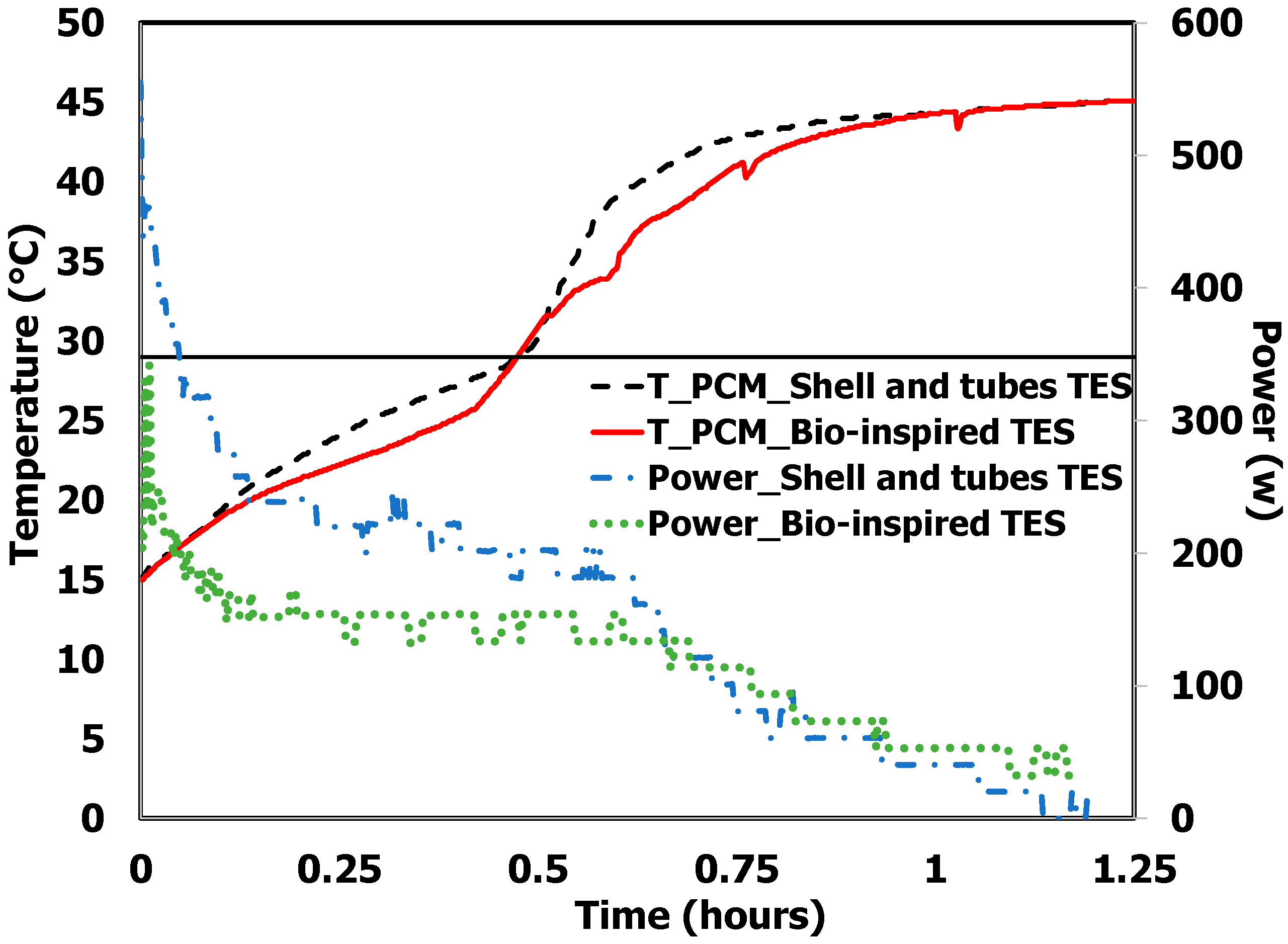
From
Figure 5, it is apparent that both the shell-and-tube and the bio-inspired TES tank took a similar amount of time (0.45 h and 0.49 h) to raise the temperature of the PCM from 15 °C to 29 °C. The temperature vs. time slopes of both cases were alike during the early stages of the charging cycle. Following the onset of the phase change process, there is only a small discrepancy in the charging rate between the conventional shell-and-tube and the bio-inspired TES tanks. Although the bio-inspired TES tank’s charging performance was modest, it was nearly as good as that of the shell-and-tube tank.
Each of the two types of TES tanks—conventional shell-and-tube and bio-inspired—had an entirely different geometry. The bio-inspired TES tank design resembles a near cylindrical container, with the HTF tubes that enter from the bottom, branch in the center, and emerge as a single tube at the end. TES tanks with the conventional shell-and-tube design are shaped like rectangular containers, with the HTF tube beginning at one end and extending to all parts of the tank in a serpentine manner until it emerges at the other end.
During the pre-charging cycle, most of the heat is uniformly transferred to every area of the contained n-octadecane in the traditional shell-and-tube TES tank because the HTF enters the tank from one end and exits from the other. In contrast, the HTF enters the bio-inspired TES tank from the bottom, some of it divides through the branches, and some of it goes directly to the top. Therefore, the temperature of the n-octadecane rises first in the bottom, core area of the bio-inspired TES tank and in close proximity to the HTF tube walls, then spreads outward in a radial direction with respect to the HTF tubes at a rate determined by the n-octadecane’s solid phase thermal conductivity.
As the charging cycle progresses, natural convection occurs equally throughout all the cross sections of the traditional shell-and-tube TES tank. In contrast, in the bio-inspired TES tank, the n-octadecane located at the bottom of the tank, the core regions of the tank, and the area close to the tube walls initially turn liquid. Furthermore, the n-octadecane present throughout the tank’s core must melt in order for natural convection to happen more rapidly in the bio-inspired TES tank. Therefore, when comparing the bio-inspired TES tank design to the traditional shell and tubes, the charging rate efficiency was not high.
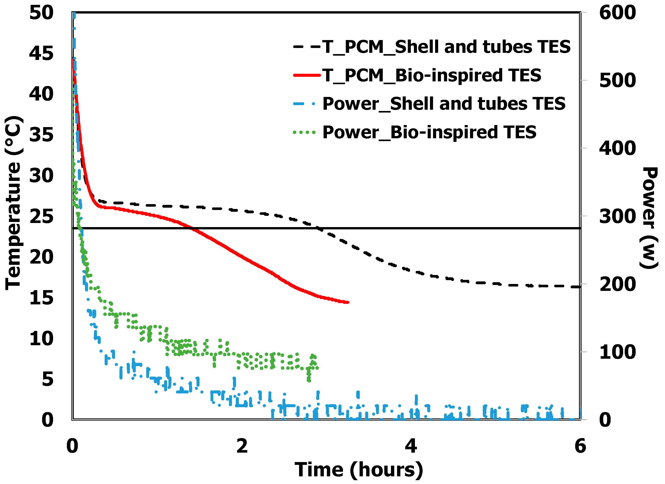
During the initial stages of the discharging cycle, the temperature vs. time profile was similar among the shell-and-tube and bio-inspired TES tanks. From
Figure 6, it is evident that the onset of the phase change process (liquid phase to solid phase) happens in the same time frame in the TES tank type. However, following the onset of the phase change process, the discharging rate was substantially higher for the bio-inspired TES tank.
Figure 6 also shows that the time required for the TES tank to discharge the heat stored in the PCM was 1.4 h for the bio-inspired TES tank, 52% less than the shell-and-tube TES tank (2.8 h). Although the conventional TES tank transmitted more power during the charging cycle, the bio-inspired TES tank transferred more power during the discharging cycle. This might result from the PCM’s ability to disperse heat from the bio-inspired TES tank more quickly than it would in a shell and tube arrangement because of the increased heat transfer surface area created by replicating the biological structure of the human body. A similar kind of research was conducted by the authors of [
25]; however, it compared the thermal performance of commercially available finned shell-and-tube TES tanks with commercially available shell-and-tube TES tanks. It was found that during the phase transition, the finned shell-and-tube TES tank transferred around 25.1 to 27.7% more power than the conventional shell-and-tube TES tank during the discharging cycle. Nonetheless, in this instance, the power transferred by the bio-inspired TES tank was 208% greater than that of the conventional shell-and-tube TES tank. When compared to the finned shell-and-tube TES tank, the power transfer percentage enhancement was considerably larger. However, the amount of PCM was maintained the same in all the TES tanks.
3.2. Effect of Operating Parameters
3.2.1. Influence of Flow Rate
The charging and discharging characteristics of the bio-inspired TES tank have also been accessed by varying the HTF mass flow rate. The HTF was pumped into the TES tank at three different mass flow rates: 1.5 kg/min, 3 kg/min, and 6 kg/min. However, the operating temperature range was maintained constant for all flow rates.
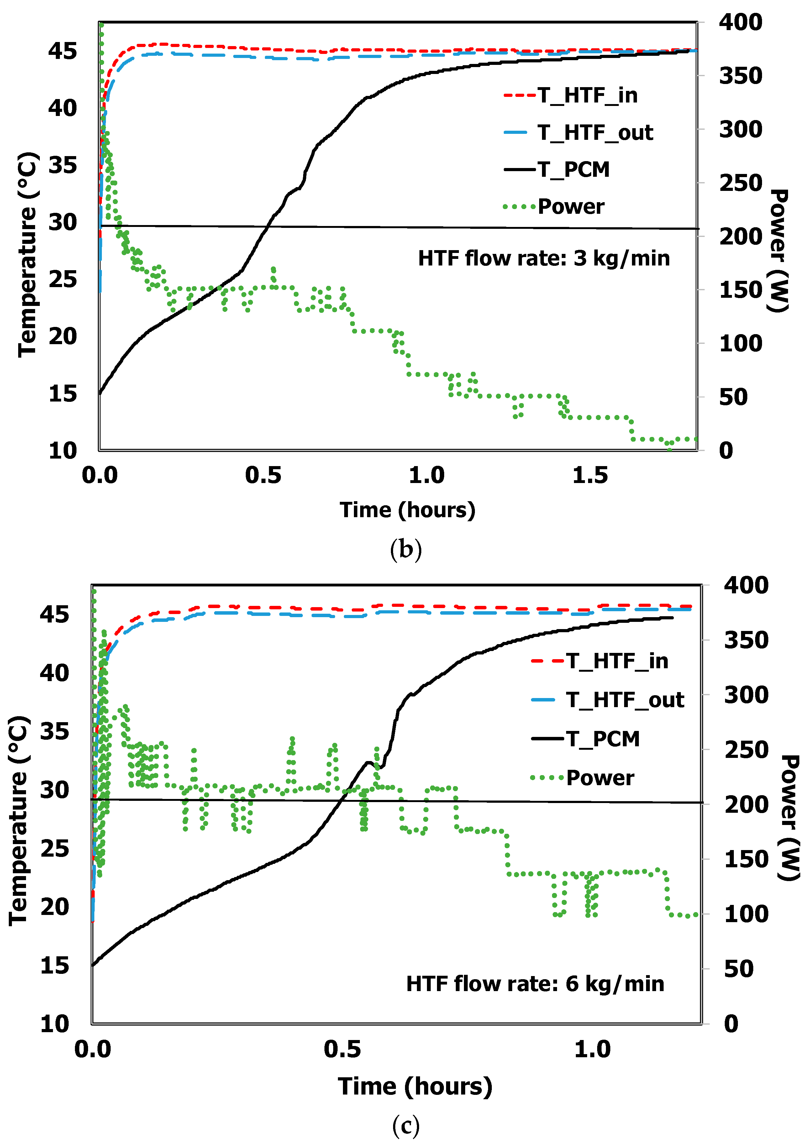
The charging characteristics of the bio-inspired TES tank under three distinct mass flow rates are shown in
Figure 7. The PCM sensible heat component (solid phase and liquid phase) and latent heat component are encompassed within the temperature window. Early in the charging cycle,
Figure 7 illustrates a notable temperature differential between the HTF inlet and HTF outlet because the PCM was at a low temperature (15 °C) during the initial stages of the charging cycle and absorbed most of the heat transported by the HTF. Nevertheless, regardless of the HTF mass flow rate, the temperature difference between the HTF inlet and outlet remained fairly constant during the phase change process. Following the phase transition process, the temperature differential diminished and approached zero because the heat was only absorbed as sensible heat by the liquid PCM.
Figure 7 also shows the power transferred by the bio-inspired TES tank during the charging cycle. There was an apparent fluctuation in the power transferred by the TES tanks early in the charging cycle. This is because, prior to the commencement of the charging cycle, the HTF confined in the tubes of the PCM tank was at the same temperature as the PCM. An abrupt heat transfer occurred when the hot HTF entered the tank during the charging cycle and caused a substantial temperature difference between the HTF inlet and HTF outlet. This irregular power profile reached a consistent state when all of the cold HTF that was held in the TES tank was completely removed, accompanied by a notable rise in PCM temperature. The power transferred by the TES tanks approached a constant value during the phase transition, and then it started to decline during the post-melting stage.
The rate of heat transfer during the phase transition is significantly affected by the mass flow rate of the HTF. The power profile of the TES tank remained consistent across different HTF mass flow rates despite variations in magnitude.
Figure 7 clearly shows that the TES tank with the HTF mass flow rate of 6 kg/min had the largest power output of between 175 W and 250 W during the phase transition process.
A comparison was made between various HTF mass flow rates and the amount of time needed for the PCM temperature to increase from 15 °C to 29 °C. It came to light that the HTF mass flow rate correlates directly with the time. With a 6 kg/min HTF flow rate, the bio-inspired TES tank approached 29 °C in the least amount of time (0.47 h) across all the flow rates. However, with flow rates of 1.5 kg/min and 3 kg/min, it took 0.52 and 0.49 h to reach 29 °C, respectively.
The discharging characteristics of the bio-inspired TES tank under three distinct mass flow rates are depicted in
Figure 8. The figure makes it clear that, during the initial stages of the discharging cycle, there was a substantial temperature differential between the HTF inlet and HTF outlet since the PCM was at a high temperature (45 °C) during the initial stages of the discharging cycle. However, regardless of the HTF mass flow rate, the temperature difference between the HTF inlet and outlet remained fairly constant during the phase change process. Following the phase transition process, the temperature differential diminished and approached zero because the heat is only released as sensible heat by the solid.
The power transferred by the TES tank during the discharging cycle exhibits a similar type of fluctuation as observed in the charging cycle. This occurred as the hot fluid held inside the TES tank was flushed by the new cold fluid during the discharging cycle. After the hot fluid that was confined in the TES tank was completely removed, the PCM temperature dropped, resulting in reduced variation in power. As can be seen in
Figure 8, the TES tank with the HTF mass flow rate of 6 kg/min had the highest power output throughout the phase transition process. This maximum power ranged between 145 W and 185 W during the discharging cycle. The time required for the PCM temperature to drop from 45 °C to 23.5 °C is defined as the discharging time. The bio-inspired TES tank with a 3 kg/min HTF flow rate took the least time (1.4 h) to discharge the PCM. However, those with flow rates of 1.5 kg/min and 6 kg/min required 1.6 h to reach 23.5 °C.
3.2.2. Influence of HTF Inlet Temperature
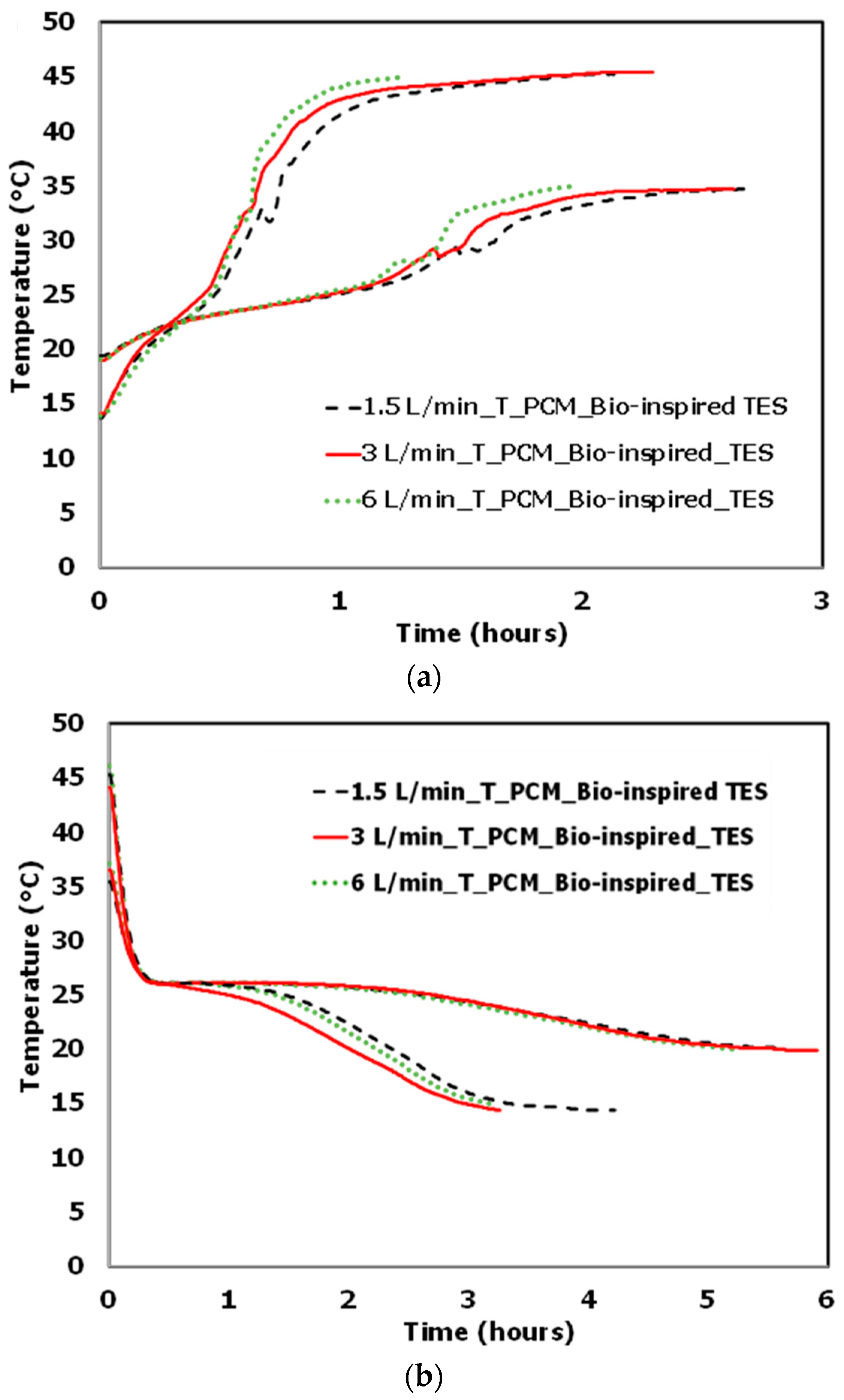
The effect of the HTF inlet temperature on the charging and discharging behavior of the bio-inspired TES tank was explored at three different mass flow rates of the HTF. Accordingly, the operating temperature window was reduced from 15–45 °C to 20–35 °C for comparison. The bio-inspired TES tank was charged with two different HTF inlet temperatures, 45 °C and 35 °C, and discharged with two different HTF inlet temperatures, 15 °C and 20 °C.
Figure 9 shows that for the TES system supplied by the higher/lower HTF inlet temperature, there was a significant increase in the rate of PCM melting during the charging cycle and solidification during the discharging cycle, respectively. In those cases, the PCM temperature changed rapidly during the charging and discharging cycles because of the larger temperature difference between the HTF and PCM temperatures. The PCM melted and solidified more quickly during the charging and discharging processes, respectively, because of the increased heat transfer rate brought about by the higher/lower operating temperature.
Figure 10 shows a comparison of the mean power for different HTF flow rates and HTF operating temperatures for both charging and discharging cycles. It is evident that the mean power transferred by the TES tank is more significantly impacted by the inlet temperature of the HTF.
Figure 10 also indicates that with an increase in HTF flow rate, the mean power produced by the bio-inspired TES tank increased in both operating temperature ranges. It was additionally found that the bio-inspired TES tank with the HTF flowing at 6 kg/min had the highest mean power transferred in both operational temperature ranges during the charging and discharging cycles. The highest mean power transferred by the bio-inspired TES is, however, proportional to the temperature at which the HTF transports its thermal energy. During the charging and discharging cycles, HTF flowing at 6 kg/min with the wider operating range had 133.6% and 101.5% higher mean power transferred, respectively, compared to the lower operating temperature range.
As a consequence, the change in HTF inlet temperature has a strong influence on the charging and discharging time of the PCM. When the HTF temperature was raised from 35 °C to 45 °C, the PCM melting time was significantly shortened from 1.29 h to 0.47 h.
The Ragone plot (
Figure 11) makes it clearly apparent that the bio-inspired TES tank performed better than the conventional shell-and-tube TES tank design. In particular, the bio-inspired TES tank operated optimally in the operational temperature range of 15 °C to 45 °C and at an HTF flow rate of 6 kg/min.
4. Conclusions
A TES tank inspired by biological architecture was built using additive manufacturing technology to enhance the TES tank’s thermal performance during charging and discharging cycles. The goal of using additive manufacturing technology was to enhance the heat transfer phenomenon. Heat transfer can occur at a faster rate because a bigger thermal conductivity channel is created when additive manufacturing technology is used to reduce the number of discrete joints in the design. To examine the bio-inspired design’s impact, the thermal performance of the bio-inspired TES was compared to that of a conventional shell-and-tube tank as a baseline. The performance of the bio-inspired TES tank was also investigated with variations in HTF operating temperature and mass flow rate.
It was found that while the PCM charging rates in the bio-inspired TES tank and the conventional shell-and-tube TES tank were similar, the bio-inspired TES tank’s discharging rate was significantly higher. The bio-inspired TES tank needed less time (52%) to release the heat stored in the PCM than the conventional TES tank. Additionally, it was found that the thermal performance of the bio-inspired TES tank was significantly impacted by HTF inlet temperature and, to a lesser extent, by the mass flow rate. When compared across different mass flow rates and operating temperatures, the HTF at 6 kg/min and within a higher temperature range of operation exhibited superior thermal performance.
The manuscript findings emphasize that the integration of a biomimicry technique into the design of a TES tank serves as a proof of concept for improved thermal performance. Compared to the traditional shell and tube design, it was discovered that the discharging performance improved significantly more than the charging performance. Further optimization is needed to exploit the full potential of this new TES concept and achieve even better thermal storage capacity and thermal performance, which should consider key aspects of TES tanks like thermal effectiveness, pressure drop, energy density, or homogeneity in temperature distribution.


 ,
, 


