Article

Innovative Methodology for Multi-View Point Cloud Registration in Robotic 3D Object Scanning and Reconstruction

1
Department of Mechanical Engineering, National Taiwan University, Taipei 10617, Taiwan
2
Institute of Automation Technology, National Taipei University of Technology, Taipei 10608, Taiwan
3
Department of Mechatronics, School of Mechanical Engineering, Hanoi University of Science & Technology, No. 1 Dai Co Viet Road, Hanoi 112400, Vietnam
*
Author to whom correspondence should be addressed.
Submission received: 23 December 2015 / Revised: 26 April 2016 / Accepted: 28 April 2016 / Published: 5 May 2016
(This article belongs to the Special Issue Selected Papers from the 2015 International Conference on Inventions)

Abstract

:
The paper is concerned with the problem of multi-view three-dimensional (3D) point cloud registration. A novel global registration method is proposed to accurately register two series of scans into an object model underlying 3D imaging digitization by using the proposed oriented bounding box (OBB) regional area-based descriptor. A robot 3D scanning strategy is nowadays employed to generate the complete set of point cloud of physical objects by using 3D robot multi-view scanning and data registration. The automated operation has to successively digitize view-dependent area-scanned point cloud from complex-shaped objects by simultaneous determination of the next best robot pose and multi-view point cloud registration. To achieve this, the OBB regional area-based descriptor is employed to determine an initial transformation matrix and is then refined employing the iterative closest point (ICP) algorithm. The key technical breakthrough can resolve the commonly encountered difficulty in accurately merging two neighboring area-scanned images when no coordinate reference exists. To verify the effectiveness of the strategy, the developed method has been verified through some experimental tests for its registration accuracy. Experimental results have preliminarily demonstrated the feasibility and applicability of the developed method.

Graphical Abstract

1. Introduction

Recently, automated three-dimensional (3D) object digitization, known under various terminologies such as 3D scanning, 3D digitizers or reconstruction, has been widely applied in many applications, such as 3D printing, reverse engineering, rapid prototyping and medical prosthetics. According to the sensing principle being employed, the current solutions can be generally classified into two main categories, namely hand-guided and automated scanning techniques. Hand-guided scanning allows for acquiring arbitrary shapes [1,2]. However, the effectiveness of this scanning method highly depends on the skills of the user and the scanning process is generally time-consuming. In contrast, the automated scanning solution using turntable-based 3D scanners is faster, less expensive, more automated, and easier to use. However, it is still not able to reconstruct objects with arbitrary or complex geometry [3,4]. To enhance the efficiency, the six-axis robot arm integrated with 3D imaging scanners has recently emerged as a technical developing trend for 3D surface scanning for objects with arbitrary or complex geometry [5,6,7]. Both Callieri [5] and Larsson [6] presented a system for automated 3D modeling consisting of a 3D laser scanner, an industrial six-axis robot and a turntable. The advantage of this system is that it automatically achieves the shape of the object from initial scanning and thus, if possible, will scan the object using an orientation of the scanner which gives the most accurate result. Meanwhile, an autonomous 3D modeling system, consisting of an industrial robot and a laser striper for efficient surface reconstruction of unknown objects was proposed by Simon Kriegel [7]. The system iteratively searches for possible scan paths in the local surface model and selects a next-best-scan (NBS) in its volumetric model. The data reconstruction of the robotic scanning systems reviewed above is mainly performed in two steps: data registration and data merge. First, an initial transformation matrix between two neighboring area scans can be traditionally determined by using the nominal scanning position of the robot arm or turntable as a starting reference, although it is not always accurate due to the unavoidable robot positioning errors. Thus, the matrix can serve as a reasonable initial estimate by using the Iterative Closest Point (ICP) algorithm [8] for further refinement of the transformation matrix. However, due to the lack of a global registration between successively scanned data, the existing scanning techniques still fail to robustly satisfy accurate object digitization with 100% surface coverage. Figure 1 shows two cases that are missing some parts of the object surfaces after performing automated object digitization using robot scanning.
The above issue is mainly caused by the fact that 3D sensor cannot measure point data from the scanned object surface that is in contact with its supporting ground. To resolve the issue, the object can be reoriented manually or automatically by using a robot grabber. Nevertheless, the changing orientation of the object produced by these two methods will definitively lose the initial pose estimate from before and after the orientation change. To estimate the pose transformation, some existing algorithms, such as local descriptor–based coarse alignment [9,10,11], use local-regional surface characteristics. As a general case, to compute the initial pose estimate, the geometric distances between corresponding 3D points existing in different views are minimized. The most common correspondences are points, curves and surfaces. The point signature [9] is a point descriptor for searching correspondences, which describes the structural neighborhood of a 3D point by the distances between neighboring points and their corresponding contour points. Johnson and Hebert proposed the concept of a spin image [10] to create an oriented point at a vertex in the surface, which is a two-dimensional (2D) histogram containing the number of points in a surrounding supporting volume. More recently, Tombari et al. [11] presented a 3D descriptor called the Signature of Histograms of OrienTations (SHOT) that encodes information about the surface within a spherical support structure. These methods generally work well for objects with unique local geometric characteristics. However, the methods can easily lead to less discrimination or sensitivity when dealing with object geometry having symmetrical or plural repeating surface contours. Therefore, modeling scanning completion with 100% surface coverage still remains one of the most challenging problems in current 3D object digitization.
Thus, accurately registering point cloud of two series of scanned point cloud into the reconstructed object model without an established coordinate reference has proven to be a difficult process [8,9,10,11,12]. To overcome the above difficulty, an automated robot scanning system integrated with a NTU-developed optical 3D measuring probe (NTU represents National Taiwan University) is developed on a global registration method to accurately register two series of scans into an object model underlying 3D imaging digitization by using the proposed oriented bounding box (OBB) regional area-based descriptor. The proposed descriptor is used to register two series of scans by matching the hardware and basic system configuration as well as data processing algorithms such as preprocessing, overlapping detection and robot path planning, which have been described in [12].

2. Global Registration Method Based on the OBB Regional Area-Based Descriptor

2.1. Principle Concept and Flow Chart Diagram of the Global Registration Method

To find the transformation between two series of scans that are acquired from multiple single scans, the OBB regional area-based descriptors of source point cloud are matched with the descriptors of the target point cloud. Figure 2 illustrates the concept of the proposed registration method based on the OBB regional area-based descriptor to register two series of scans which are represented by the red and green point cloud for the target and source 3D point cloud that are scanned and obtained from the optical probe. Each of the proposed descriptors includes two critical components. The first component contains the information about the OBB of the point cloud. Each OBB is represented by a datum corner, C(xC, yC, zC), and three vectors, CC1(xmax, ymax, zmax), CC2(xmid, ymid, zmid), CC3(xmin, ymin, zmin), corresponding with the maximum, middle, and minimum dimensions of the OBB, respectively. The second component represents the spatial distribution of the surface area of the object in the OBB. The similarity between the regional area-based descriptor representing the source point cloud and the regional area-based descriptor representing the target one is then determined by using the normalized cross-correlation.
To make the proposed method clear in its operation procedure, the following flow chart diagram, shown in Figure 3, as well as Algorithm 1, is used to describe the proposed method in its main five steps. In step 1, the boundary points located near the scanning point missing zone can be detected through the geometric relationship with the support plane, using a set of connected edges that satisfy two conditions, in which all the boundary edges in the point missing zone have a similar orientation and each edge lacks an assigned triangle, either on the left or on the right side [7]. Then, the oriented bounding box (OBB), which is a rectangular bounding box that covers all the object point cloud, is determined in step 2. In the next step, the generation of the descriptors of the point cloud is performed. Then, the matching process between the descriptors is implemented and achieves the initial transformation that can be used for further refined registration using ICP.
Algorithm 1
Input: Two series of scans P and Q
Output: Transformation matrix
1Estimate the boundary of the missing points and enclose the missing regions
2Determine individual OBBs of the two series of scans
3Generate the descriptors of P and Q
3.1Calculate the OBB regional area-based descriptor of P
3.2Translate the OBB of P to Q using the translation matrix defined by the centers of gravity of P with its estimated missing points and Q with its estimated missing points
3.3Rotate Q around the three axes of the coordinate system defined by the center of gravity of Q as the origin and the three unit vectors considered as the three directions of the OBB of point cloud P with every increment Δθ on each axis, generating the OBB regional area-based descriptors of Q
4Match the descriptors between P and every Q having an increment Δθ of rotation performed in Step 3.3
5Determine the best machine and obtain the initial transformation matrix

2.2. Estimation of Missing Regions and Initial Translation

Assuming that two series of scans to be registered are represented as two sets of unorganized points P = {p1, p2,…, pk} and Q = {q1, q2,…, qk}, the initial transformation, which represents the coarse alignment between the two series, can be estimated as follows.
If P and Q represent the same free-form shape, the least squares method can be used to calculate the initial rotation and translation by minimizing the sum of the squares of alignment errors. Let E be the sum of the squares of alignment errors. Accordingly,
E = i = 1 k e i 2 = i = 1 k p i R q i t 2
where R is the rotation matrix, t is the translation vector, pi and qi is the corresponding point pair between the P and Q point clouds.
Let p ¯ be the centroid of the set of corresponding points in P {p1, p2, …, pk} and q ¯ be the centroid of the set of corresponding points in Q {q1, q2, …, qk}. Then p ¯ and q ¯ can be defined as:
p ¯ = 1 k i = 1 k p i
q ¯ = 1 k i = 1 k q i
The new coordinates of points are denoted by:
p ' i = p i p ¯
q ' i = q i q ¯
Note that:
i = 1 k p ' i = i = 1 k ( p i p ¯ ) = i = 1 k p i k p ¯ = 0
i = 1 k q ' i = i = 1 k ( q i q ¯ ) = i = 1 k q i k q ¯ = 0
The registration error term is then expressed and rewritten as:
e i = p i R q i t = p ' i R q ' i t
where t = t p ¯ + R q ¯
The sum of the squares of the errors becomes:
E = i = 1 k p ' i R q ' i t 2     = i = 1 k p ' i R q ' i 2 2 t i = 1 k [ p ' i R q ' i ] + k t 2     = i = 1 k p ' i R q ' i 2 + k t 2
The first term in Equation (9) does not depend on t . Therefore, the total error is minimized if t = 0 , and then:
t = p ¯ R q ¯
Therefore, the initial translation matrix can be computed based on the difference between the centroid of P and the centroid of Q.
In addition, the weight loss at the missing parts of two the scan series may result in a significant bias between the translation matrix being estimated (by the difference between the centroid of P and the centroid of Q) and the real translation matrix. The shifting of two gravity centers (the red and green points shown in Figure 4) being created using a virtual camera from a model having the centroid (white point) in Figure 4a illustrates the influence of weight loss from the missing points to the centroid point position. Assume that the two point sets are separated as shown in Figure 4b. The accurate translation matrix to merge set Q (green point cloud) with set P (red point cloud) is defined through the difference between the current centroid of P and the original centroid of the green point cloud (green points). Therefore, it is necessary to estimate the original centroid of P on the object for translation.
The boundary points located near the missing part can be detected through the geometric relationship with the support plane and using a set of connected edges that satisfy two requirements, in which all edges have a similar orientation and each edge lacks an assigned triangle, either on the left or on the right side [7] (as shown in Figure 4c). Then, the Random Sample Consensus (RANSAC) algorithm [13] is used to fit a mathematical model to the boundary and enclose the missing region by adding extra points. Therefore, the initial translation matrix can be computed based on the difference between the centroid of enclosed P and the centroid of enclosed Q. From now on, P and Q are referred to as enclosed P and enclosed Q, respectively.

2.3. Determination of Oriented Bounding Box (OBB)

The oriented bounding box is a rectangular bounding box that covers whole object point cloud. Each OBB is represented by a corner, C(xc, yc, zc), and three vectors, CC1(xmax, ymax, zmax), CC2(xmid, ymid, zmid), CC3(xmin, ymin, zmin), corresponding with the maximum, middle, and minimum dimensions of the OBB, respectively (as shown in Figure 5). The orientations of the OBB can be determined by using the covariance-based method, which is proposed by Gottschalk (1996) [14]. The algorithm is started by obtaining the centroid p ¯ ( x ¯ , y ¯ , z ¯ ) of the object point cloud:
x ¯ = 1 n i = 1 n x i y ¯ = 1 n i = 1 n y i z ¯ = 1 n i = 1 n z i
where n is the number of points in the object point cloud. The covariance matrix of the input point cloud COV is then computed as follows:
C O V = 1 n i = 1 n ( p i p ¯ ) ( p i p ¯ ) T = 1 n [ i = 1 n ( x i x ¯ ) 2 i = 1 n ( x i x ¯ ) ( y i y ¯ ) i = 1 n ( x i x ¯ ) ( z i z ¯ ) i = 1 n ( x i x ¯ ) ( y i y ¯ ) i = 1 n ( y i y ¯ ) 2 i = 1 n ( y i y ¯ ) ( z i z ¯ ) i = 1 n ( x i x ¯ ) ( z i z ¯ ) i = 1 n ( y i y ¯ ) ( z i z ¯ ) i = 1 n ( z i z ¯ ) 2 ]
The above matrix has three real eigenvalues, λ1 ≥ λ2 ≥ λ3, and three normalized eigenvectors, v1(v11, v12, v13), v2(v21, v22, v23), and v3(v31, v32, v33), respectively. These eigenvectors are considered as the three directions of the OBB. By projecting all points in the object point cloud onto the eigenvectors, three dimensions of the object can be determined as the distance between the nearest and farthest projected points in each eigenvector. Considering the coordinate system with the origin p ¯ and three unit vectors v1, v2, and v3 (as shown in Figure 6), the coordinates of the point pi(xi, yi, zi) in this coordinate system are determined by following equation:
[ x i y i z i ] = [ v 1 e 1 v 1 e 2 v 1 e 3 v 2 e 1 v 2 e 2 v 2 e 3 v 3 e 1 v 3 e 3 v 3 e 3 ] [ x i x ¯ y i y ¯ z i z ¯ ]
[ x i y i z i ] = [ v 11 v 12 v 13 v 21 v 22 v 23 v 31 v 32 v 33 ] [ x i x ¯ y i y ¯ z i z ¯ ]
[ x i y i z i ] = T [ x i x ¯ y i y ¯ z i z ¯ ]
where e1, e2, and e3 are the three unit vectors of the original coordinate system.
Note that matrix T is the orthogonal matrix. It means that T−1 = TT.
Let:
x m i n = min { x i , i = 1 , ... , n } ,   x m a x = max { x i , i = 1 , ... , n } y m i n = min { y i , i = 1 , ... , n } ,   y m a x = max { y i , i = 1 , ... , n } z m i n = min { z i , i = 1 , ... , n } ,   z m a x = max { z i , i = 1 , ... , n }
The parameters of the OBB can be determined as follows:
{ x C = x ¯ + v 11 x m i n + v 21 y m i n + v 31 z m i n y C = y ¯ + v 12 x m i n + v 22 y m i n + v 32 z m i n z C = z ¯ + v 13 x m i n + v 23 y m i n + v 33 z m i n
C C 1 = ( x max x min ) v 1 C C 2 = ( y max y min ) v 2 C C 3 = ( z max z min ) v 3

2.4. Generating Descriptors of Point Cloud

2.4.1. The OBB Regional Area-Based Descriptor

Each proposed feature descriptor includes two components [15]. The first component contains the information about the OBB of the point cloud. Each OBB is represented by a corner, C(xC, yC, zC), and three vectors, CC1(xmax, ymax, zmax), CC2(xmid, ymid, zmid), CC3(xmin, ymin, zmin), corresponding with the maximum, middle, and minimum dimensions of the OBB, respectively. The second component represents the distribution of the surface area of the object in the OBB. We assume that the three directions of the OBB are divided into k1, k2, and k3 segments (as shown in Figure 7a); the total number of subdivided boxes in the OBB is n = k1 × k2 × k3. The surface area of the object in each subdivided box Vijk (i = 0, ..., k1 − 1; j = 0, ..., k2 − 1; k = 0, ..., k3 − 1) is denoted as fv, where v = k(k1k2) + j(k1) + I; fv can be determined by subdividing the considered surface into the triangle mesh [16] (as shown in Figure 7c). The distribution of Sv is defined as the regional area-based descriptor, shown in Figure 7d. Thus, the feature descriptor FV can be described as follows:
F V = { C , C C 1 , C C 2 , C C 3 , f 0 , , f v , , f n V }
where nV = k1k2k3 − 1.

2.4.2. Generating Database and Calculating Descriptors

Firstly, the regional area-based descriptor of point cloud P is computed as FVP = {CP; CPC1P, CPC2P, CPC3P, fPv, v = 0, …, n} in the OBB of P. Then we shift the OBB of P to Q using the translation matrix defined by the centers of gravity of P and Q. We consider the coordinate system OQxqyqzq with the origin OQ is the center of gravity of Q and three unit vectors ν1, ν2, and ν3, which are considered as the three directions of the OBB of point cloud P. Rotating Q around the three axes of the coordinate system OQxqyqzq is performed with every increment Δθ on each axis. For each rotation, the regional area-based descriptor Q in the OBB of P is FVQi = {CQi; CQiC1Qi, CQiC2Qi, CPC3Qi, fQv, v = 0, …, n} which can be then determined as described as Algorithm 2. To enhance the accuracy, the descriptors FVP and FVQi can ignore the subdivided boxes in which the missing parts of point cloud P are located.
Algorithm 2. Generation of database
Input: Series of scans Q = {q1, q2,…, qn}, the OBB of P
Output: A set of descriptors of Q at different poses
for l = 0, 1, 2, ..., 2π/Δθ
  for j = 0, 1, 2, ..., π/Δθ
    for k = 0, 1, 2, ..., (π/2)/Δθ
      θxl = l*Δθ, θyj = j*Δθ, θzk = k*Δθ
      R = Rxxl) Ryxj) Rzzk)
       Q R Q i
      FVQi = {fQiv, v = 0, …, n}
    end_for
  end_for
end_for

2.5. Matching Descriptors

In the first step of the matching process, the OBB’s parameters of point cloud P are compared with the OBB’s parameters of point cloud Qi. If the OBB matching satisfies the given condition, the regional area-based descriptor of point cloud P is then compared with the regional area-based descriptor of Qi. These two OBBs should be satisfied with the following equation:
{ C P C P 1 . C Q C Q 1 C P C P 1 . C Q C Q 1 < α t h r e s h C P C P 2 . C Q C Q 2 C P C P 2 . C Q C Q 2 < α t h r e s h C P C P 3 . C Q C Q 3 C P C P 3 . C Q C Q 3 < α t h r e s h
where αthresh is the given adequate threshold.
The similarity between the regional area-based descriptors that represent the object point clouds P and Q is determined by using the normalized cross-correlation. The normalized cross-correlation between FP = {fPv, v = 0, …, n} and FQ = {fQv, v = 0, …, n} is computed as follows:
C ( F P , F Q ) = v = 0 n ( f P v f ¯ P ) ( f Q v f ¯ Q ) v = 0 n ( f P v f ¯ P ) 2 v = 0 n ( f Q v f ¯ Q ) 2
where f ¯ P = 1 n + 1 v = 0 n f P v f ¯ Q = 1 n + 1 v = 0 n f Q v
The matching is the best in Equation (20) in which the normalized cross-correlation C ( F P , F Q ) reaches its peak.

2.6. Transformation Estimation and Refinement

After the best matching is defined, the correspondence feature vectors FVP and FVQ can be determined. Based on these feature vectors, the initial transformation matrix Tinitial between two series of scans can be estimated by aligning the frame {CQ, vQ1, vQ2, vQ3} that represents the series of scans 1 to the frame {CP, vQbest1, vQbest2, vQbest3} that represents the series of scans 2. Although the parameters of the transformation matrix can be obtained in the initial registration, the accuracy may not be satisfactory due to the error caused by the limited number of the rotating Q iterations. Fortunately, a refined registration such as the iterative closest point (ICP) algorithm can be performed to achieve precise registration between multi-view point cloud.

3. Results and Discussion

3.1. Case Study on Measured Data

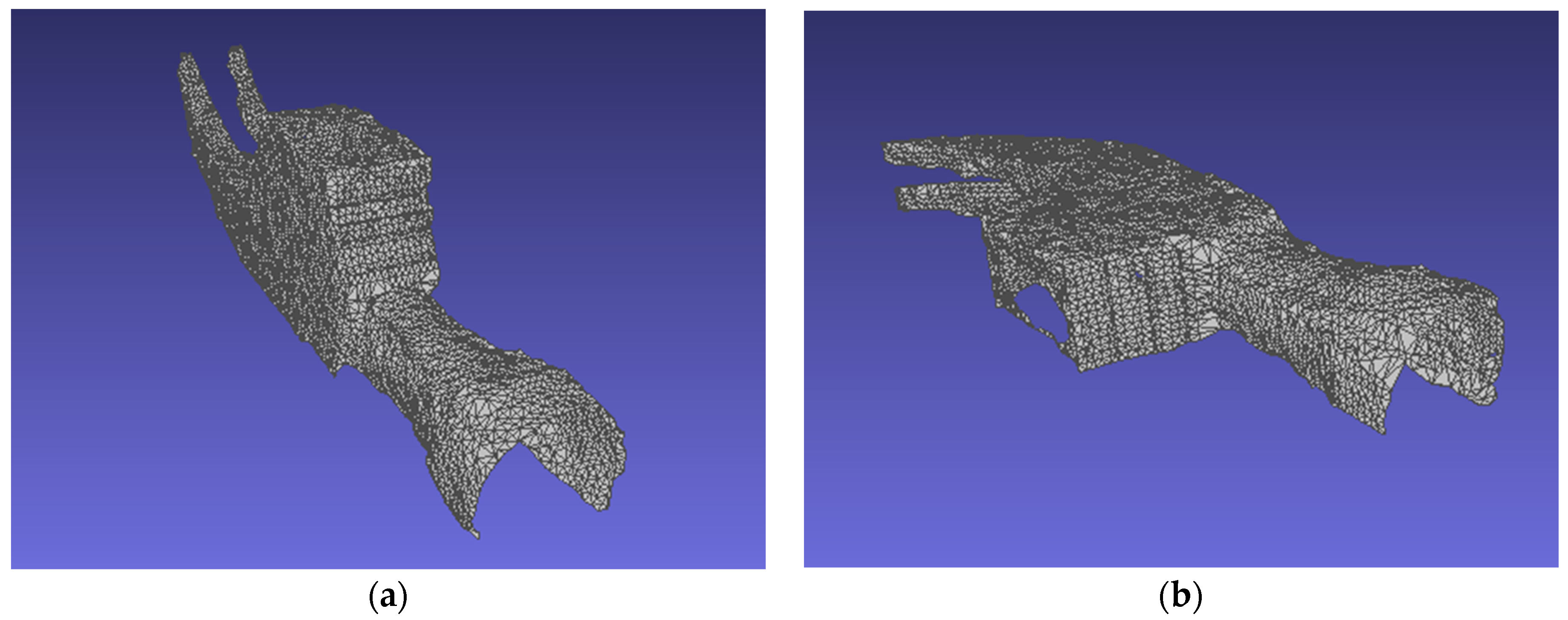
To verify the feasibility of the developed methodology, some experiments were performed and evaluated. In the experiments, the point cloud of a hammer head were acquired from the NTU-developed optical 3D measuring probe being developed by using a random speckle pattern projection and triangulation measurement principle [12,15]. The dimensions of the hammer head are approximately 110 × 35.5 × 21 mm
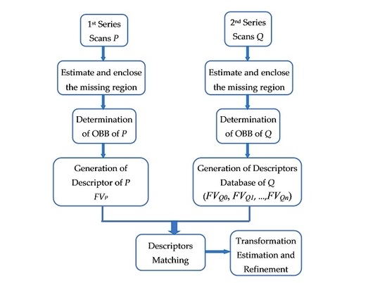
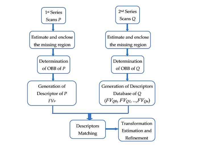
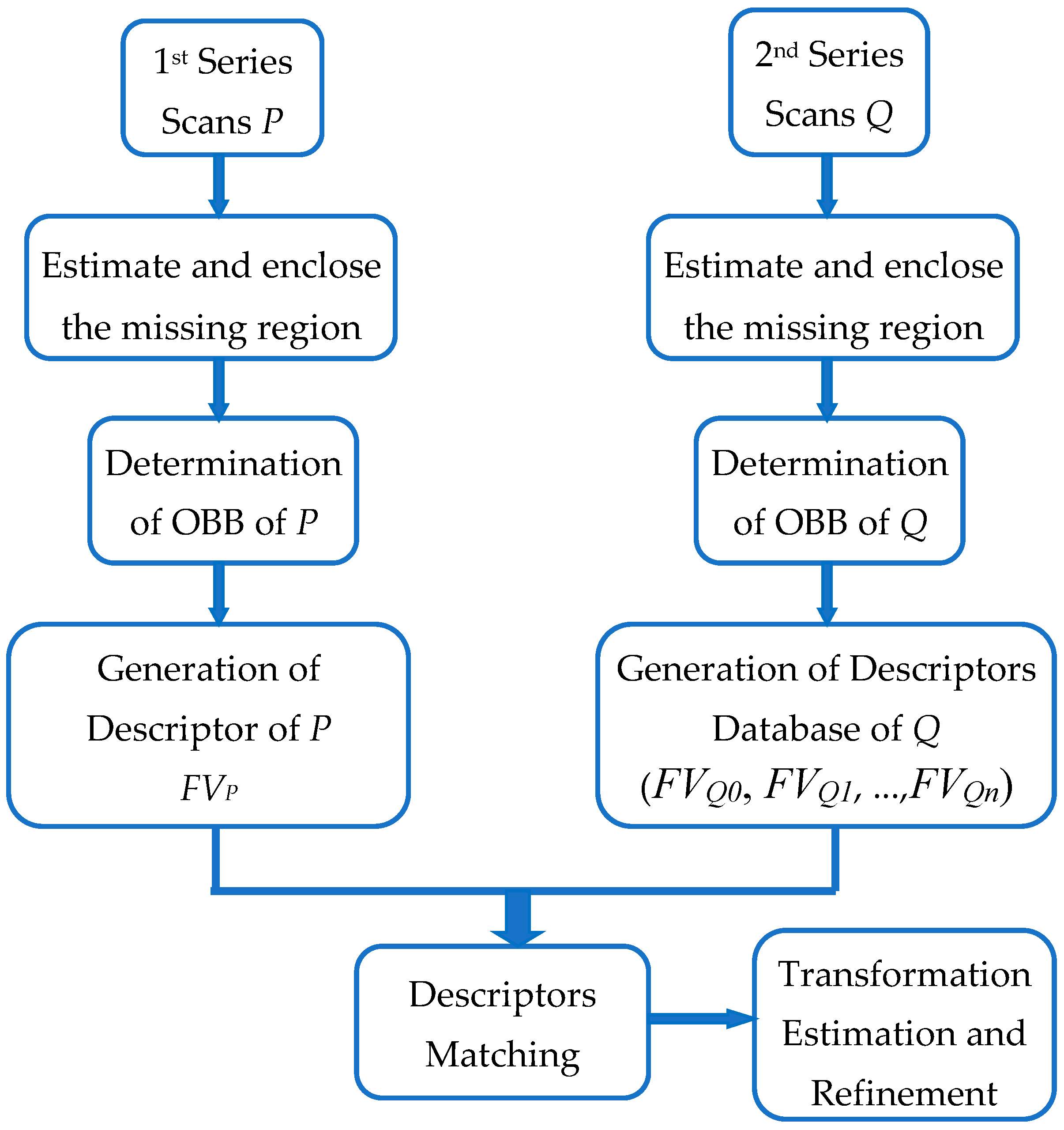
3. Firstly, the hammer head was placed on a fixed table, allowing for viewing the object from several positions around the object. However, the whole object surface could not be detected due to optical occlusion. Therefore, after the first series of automated scans to obtain point cloud P, the object was reoriented manually and the second series of automated scans was continuously carried out to acquire point cloud Q. 
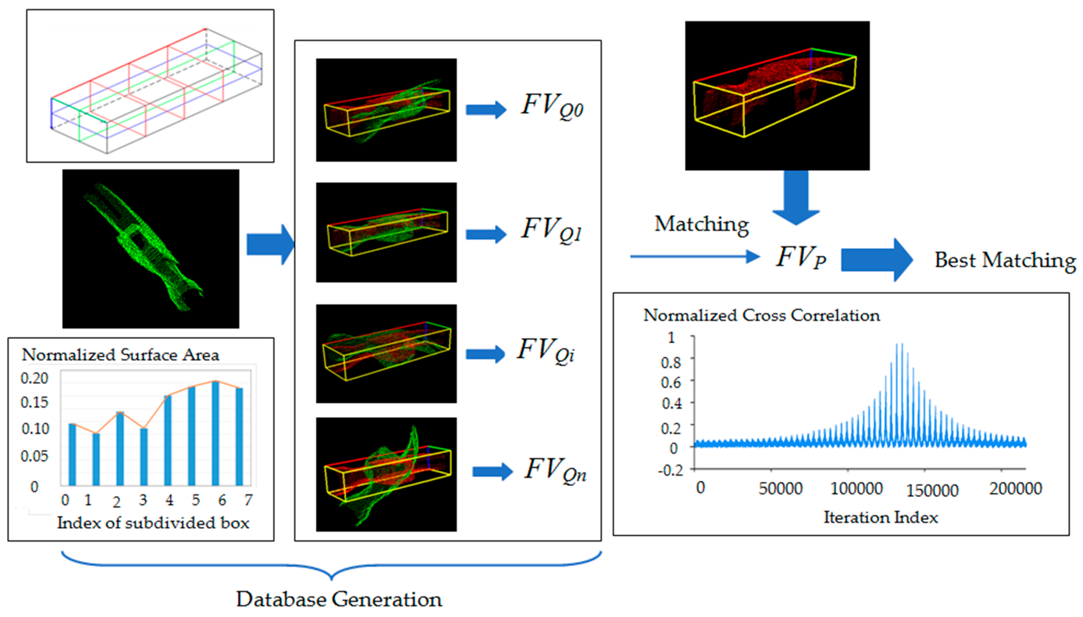
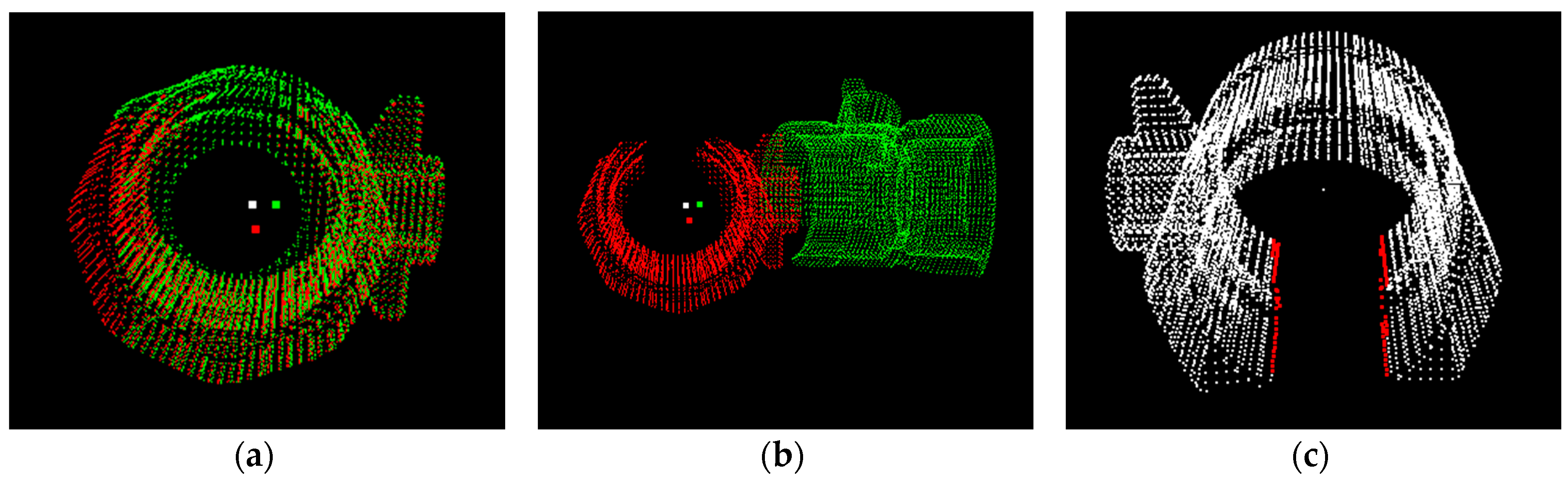
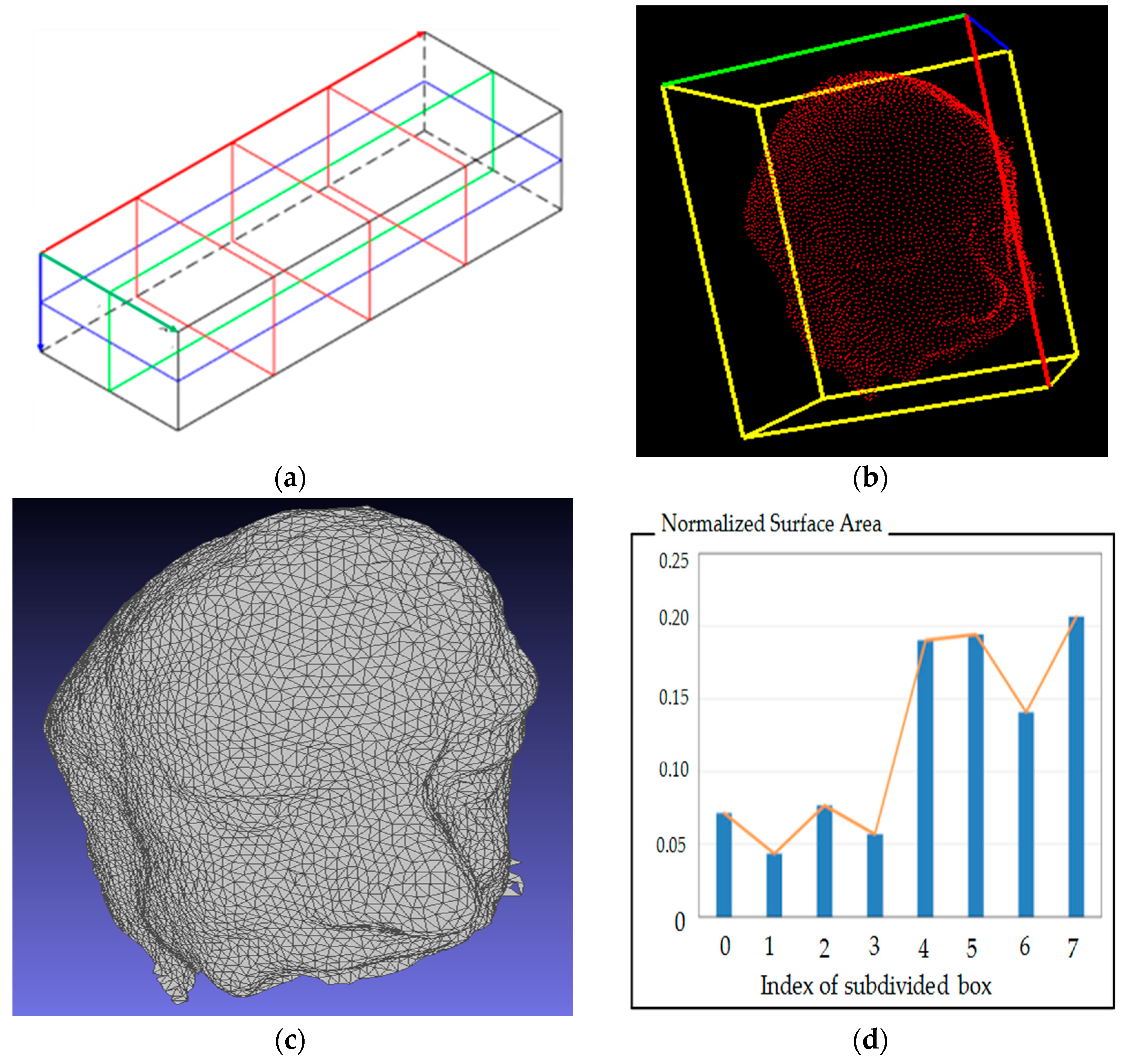
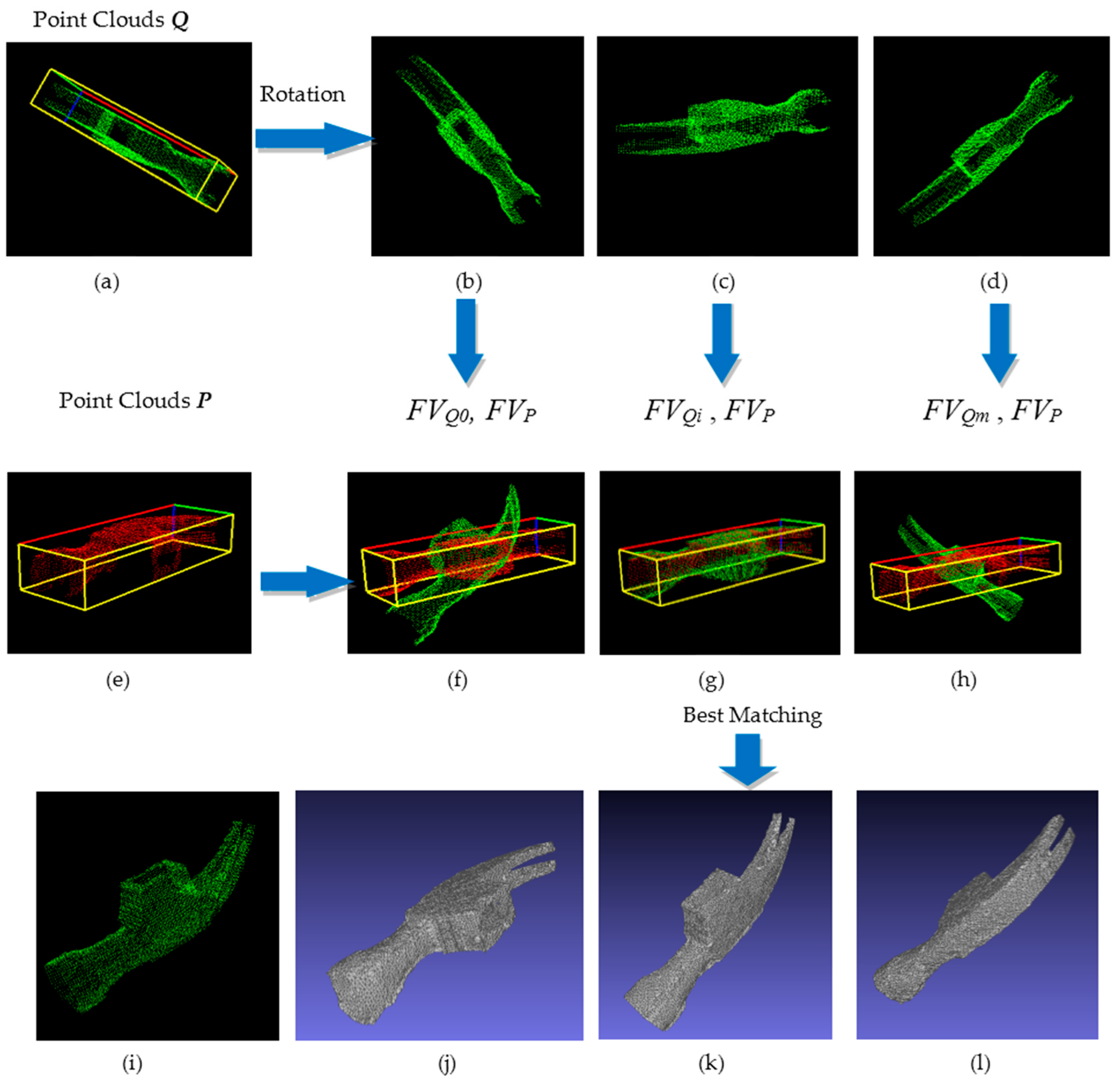
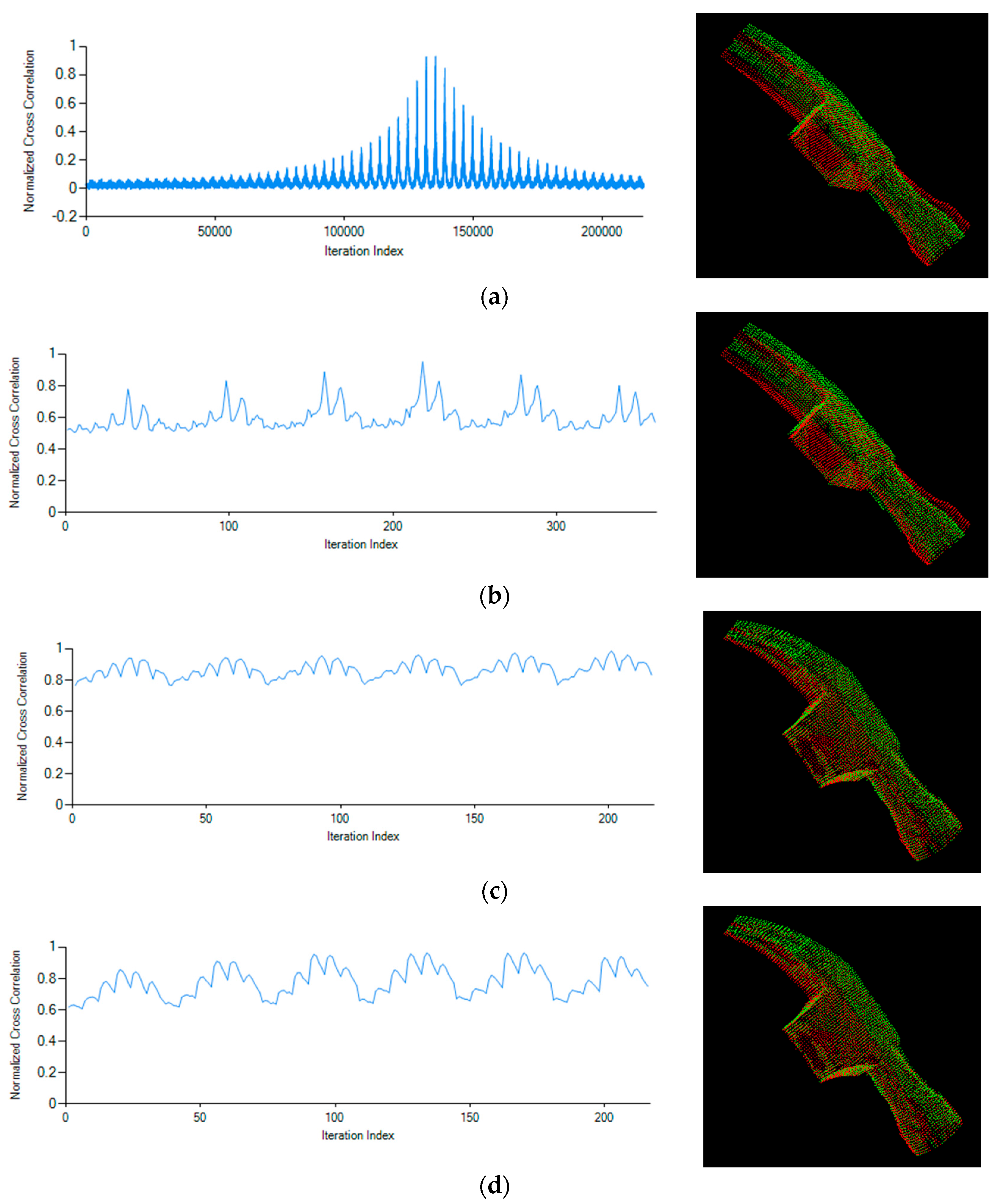
Figure 8 illustrates the coarse registration process between the two series of scans. The width of the normalized cross-correlation peak depends on the number of iterations and Δθ, as shown in Figure 9. Meanwhile, the height of the normalized cross-correlation depends on the number of OBB segments k1 × k2 × k3 and Δθ.
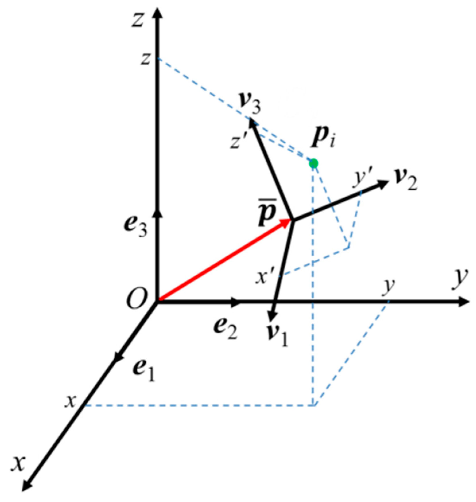
The performance of the registration can be estimated by using the distance from each overlapping point qi in point cloud Q to the fitting control point pi which is the projected point of qi onto the triangle mesh of P. If di denotes the distance between a point pi in P and its closest neighbor point qi in Q, the mean distance μ and standard deviation σ, which are used to evaluate the performance of the object registration, are computed as follows:
μ = 1 n i = 1 n d i
σ = i = 1 n ( d i μ ) 2 n 1
In this experiment, the mean deviation value is 0.0347 mm and the standard deviation value is 0.0235 mm. 
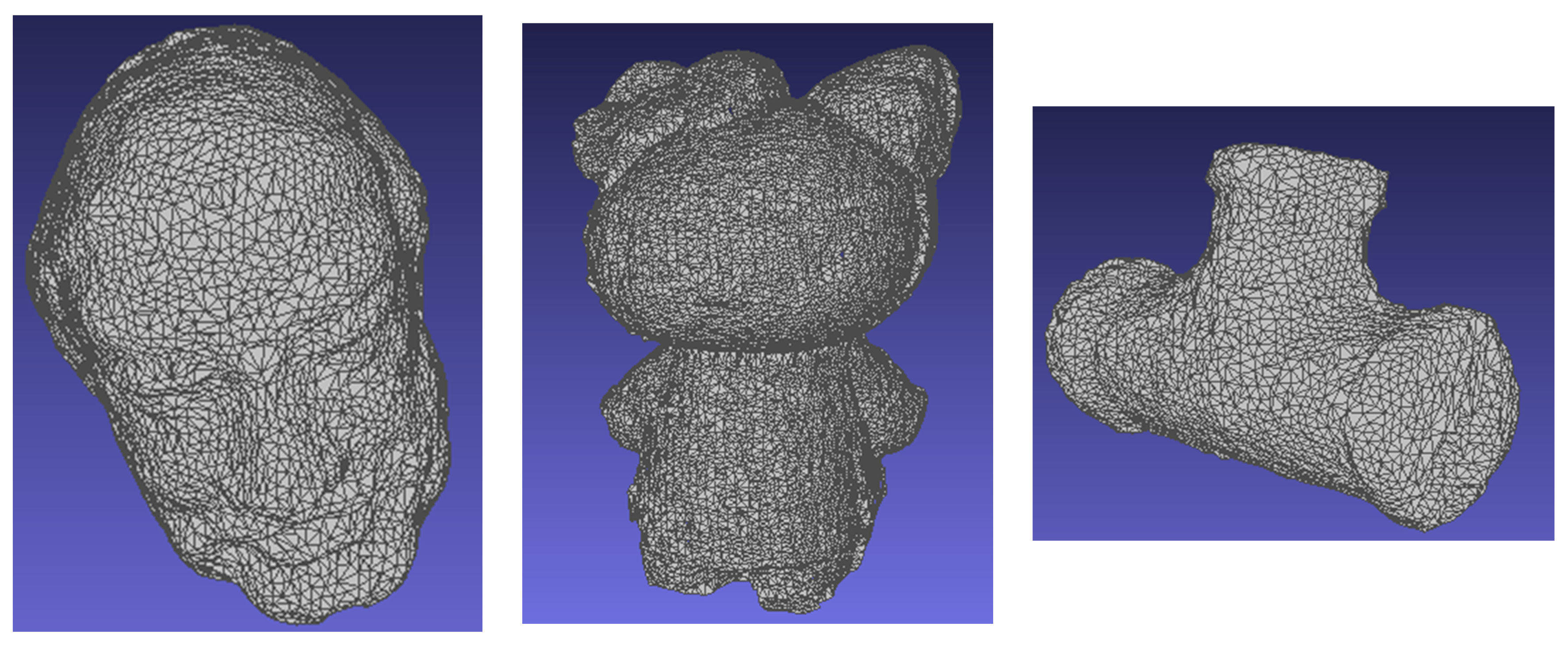
Figure 10 illustrates the other examples being achieved by the developed method.

3.2. Case Study on Synthetic Data

In this section we provide a discussion on the influence of parameters on the performance of the proposed method. In addition, a comparison against several already published local feature descriptor methods is also introduced. The considered approaches are: Spin Images (SI), Point Signatures (PS), Point Feature Histograms (PFH), and the Signature of Histograms of OrienTations (SHOT). All methods were implemented in C++ using the open source Point Cloud Library (PCL). To estimate the computation cost of the registration process, the experiments are processed on a computer with an Intel core i7 processor with 3.40 GHz and 8 GB RAM.
In real application, it is very difficult to distinguish different error sources such as shape measurement error (noise, surface sampling, etc.), correspondence error (occlusion, outliers, 
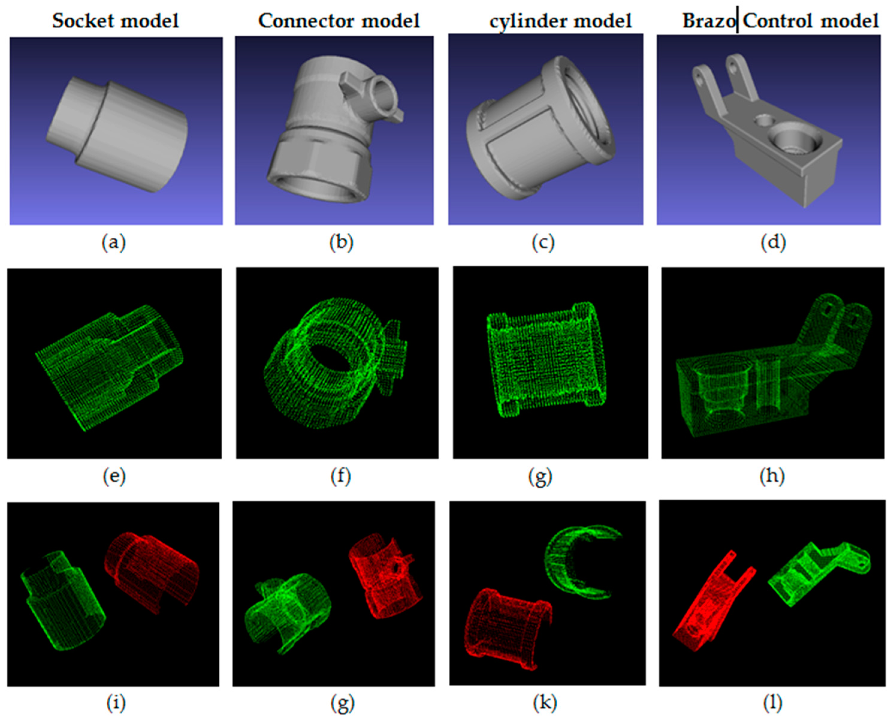
etc.), and registration error. In order to evaluate the coarse registration errors, we have generated synthetic data, which is provided by the Industrial Technology Research Institute (ITRI) (as shown in Figure 11). The dimensions of the socket model, connector model, cylinder model, and Brazo Control model are 45 × 25 × 25 mm3, 41 × 33 × 25 mm3, 35 × 35 × 35 mm3, and 86 × 53 × 30 mm3, respectively. Then, the point cloud corresponding with different views of the models are extracted by the NTU-developed virtual camera software (Precision Metrology (PM) lab, National Taiwan University, Taipei, Taiwan). The motion between green and red point cloud is a displacement of 50 mm in each axis and a rotation of π/4 around a fixed axis. Therefore, we have precise knowledge of the motion parameter rotation matrix R and translation vector t to serve as a reference for error estimation and validation of the coarse registration methods. The measures used to determine the accuracy include the rotation error and translation error. In order to evaluate the accuracy, the estimated transformation is compared to an expected one.
Results obtained show that sampling does not considerably affect the accuracy of the registration results. Thus, low resolution surfaces can be used in the proposed approach to reduce the computation time. Meanwhile, as is shown in Table 1, errors in the proposed registration algorithms extremely depend on the rotation increment Δθ (rad). To enhance the accuracy, the rotation increment should become smaller. However, the increment has a significant impact on the runtime of the proposed coarse registration process. As an example, the experiment with 1000 points in Table 1, with computation time in the case Δθ = 0.01 (rad), at 126.439 (s), was much higher than that in the case Δθ = 0.05 (rad), at only 1.063 (s).
Another important characteristic of the developed method is the total number of subdivided boxes in the OBB, n = k1 × k2 × k3. From Table 2, it can be seen that if the OBB contains many subdivided boxes, it is more expensive to find the best rotation. For a fast registration procedure, fewer subdivided boxes are preferable. However, it is also required that the number of subdivided boxes is great enough to achieve the expected rotation. For instance, in the experiment using a connector model of 1000 points, the rotation error rose to 0.057 (rad) for the OBB of n = k1 × k2 × k3 = 4 × 5 × 6, while it reached just 0.017 (rad) if the OBB of n = k1 × k2 × k3 = 7 × 8 × 9.
Besides, the ratio of the overlapped area is especially crucial. As shown in Table 3, translation and rotation errors in the proposed approach grow in direct proportion to the percentage of the non-overlapping region. This change is especially significant with over 40% of the outliers. This is because it is difficult to estimate translation exactly without a high level of overlapping. The excellent results are obtained for over 80% of shape the overlapping. In this case, the translation and rotation for tested models were at under 1.5 (mm) and 0.02 (rad), respectively. As described in the Introduction, the proposed registration method is developed to register two series of surface scans which exist with a certain degree of optical occlusion from each individual viewpoint of the probe scanning. To accurately register two series of scans under such a circumstance, it is important to have them overlap as much as possible. However, realistically, the overlapped ratio really depends on the complexity of the scanned object’s geometry and how the object is placed on the rotation table. In general, the higher the overlapped ratio between two series of scans, the more accurate the registration that can be achieved.
The result of Table 4 reveals the performances of the proposed approach and 3D key point descriptors. It shows that the developed method in this paper outperforms in registration accuracy with reasonable operation efficiency. As we know, one significant common problem using feature descriptors is that they usually fail to deal with object geometry that has symmetrical or plural repeated surface contours. We demonstrate the developed approach by using four test cases comprising two regular shapes, a Brazo and a connector, and two featureless models, a cylinder and a socket with 80% shape similarity which was provided by the Industrial Technology Research Institute (ITRI) (as shown in Figure 11). Given the reported results, it is clear that the proposed approach performs more accurately than the other methods on all the tested data. The computation efficiency of the proposed method is approximately the half of the fastest method, the Signature of Histograms of OrienTations SHOT. However, its time efficiency still ranks within a reasonable range.
To test the noise influence, the synthetic experiments were carried out with respect to three different levels of Gaussian noises: σ = 0.01, 0.02 and 0.03 (standard deviation). The coarse registration results on the connector point-sets are shown in Table 5. We found that the proposed approach is able to achieve acceptable results with a certain level of noise.

4. Conclusions

In this study, a global registration method is developed to overcome one of the most challenging problems remaining in current 3D scanning systems for accurate image registration, even with no reference coordinate existing between the neighboring scanned surface patches. The key innovation in this work is the strategy in determining a robust registration transformation between two neighboring scans. The experimental results demonstrate the validity and applicability of the proposed approach. The registration error can be controlled within a few tens of micrometers in one standard deviation for an object size reaching 100 millimeters.

Acknowledgments

The authors would like to convey their appreciation for grant support from the Ministry of Science and Technology (MOST) of Taiwan under its grant with reference number MOST 103-2218-E-001-027-MY2. The appreciation is also conveyed to the Industrial Technology Research Institute (ITRI) for providing some testing samples.

Author Contributions

Liang-Chia Chen is the chief research project coordinator which is in charge of the research management and establishment as well as forming the concept of the methodology; Dinh-Cuong Hoang is a PhD student responsible of the major development of the system and optimization of the method. Hsien-I Lin assists the research and student supervision for the research project while Thanh-Hung Nguyen contributes the method of the regional area-based surface descriptor to the development.

Conflicts of Interest

The authors declare no conflict of interest.

References

  1. Bodenmueller, T.; Hirzinger, G. Online Surface Reconstruction from Unorganized 3D-Points for the DLR Hand-guided Scanner System. In Proceedings of the 2nd International Symposium on 3D Data Processing, Visualization and Transmission, Thessaloniki, Greece, 6–9 September 2004.
  2. Strobl, K.H.; Sepp, W.; Wahl, E.; Bodenmueller, T.; Suppa, M.; Seara, J.; Hirzinger, G. The DLR Multisensory Hand-Guided Device: The Laser Stripe Profiler. In Proceedings of the ICRA, New Orleans, LA, USA, 26 April–1 May 2004.
  3. Fitzgibbon, A.W.; Cross, G.; Zisserman, A. Automatic 3D model construction for turn-table sequences. In Proceedings of the 3D Structure from Multiple Images of Large-Scale Environments, Freiburg, Germany, 6–7 June 1998; pp. 155–170.
  4. Fremont, V.; Chellali, R. Turntable-based 3D object reconstruction. In Proceedings of the IEEE Conference on Cybernetics and Intelligent Systems, Singapore, 1–3 December 2004; pp. 1277–1282.
  5. Callieri, M.; Fasano, A.; Impoco, G.; Cignoni, P.; Scopigno, R.; Parrini, G.; Biagini, G. RoboScan: An Automatic System for Accurate and Unattended 3D Scanning. In Proceedings of the IEEE 3DPVT, Thessaloniki, Greece, 6–9 September 2004; pp. 805–812.
  6. Larsson, S.; Kjellander, J.A.P. Path planning for laser scanning with an industrial robot. RAS 2008, 56, 615–624. [Google Scholar] [CrossRef]
  7. Kriegel, S.; Rink, C.; Bodenmüller, T.; Suppa, M. Efficient next-best-scan planning for autonomous 3D surface reconstruction of unknown objects. J. Real Time Image Process. Special Issue Robot Vis. 2015, 10, 611–631. [Google Scholar] [CrossRef]
  8. Besl, P.J.; McKay, N.D. A method for registration of 3D shapes. IEEE Trans. Pattern Recogn. Mach. Intell. 1992, 14, 239–256. [Google Scholar] [CrossRef]
  9. Chua, C.J.R. Point signatures: A new representation for 3D object recognition. Int. J. Comput. Vis. 1997, 25, 63–85. [Google Scholar] [CrossRef]
  10. Johnson, A.E.; Hebert, M. Using spin images for efficient object recognition in cluttered 3D scenes. IEEE Trans. Pattern Anal. Mach. Intell. 1999, 21, 433–449. [Google Scholar] [CrossRef]
  11. Tombari, F.; Salti, S.; di Stefano, L. Unique Signatures of Histograms for Local Surface Description. In Proceedings of the 11th European Conference on Computer Vision Conference on Computer Vision: Part III, Hersonissos, Greece, 5–11 September 2010; pp. 356–369.
  12. Chen, L.-C.; Hoang, D.-C.; Lin, H.-I.; Nguyen, T.-H. A 3-D point clouds scanning and registration methodology for automatic object digitization. Smart Sci. 2016. [Google Scholar] [CrossRef]
  13. Fischler, M.A.; Bolles, R.C. Random sample consensus: A paradigm for model fitting with applications to image analysis and automated cartography. Commun. ACM 1981, 24, 381–395. [Google Scholar] [CrossRef]
  14. Gottschalk, S.; Lin, M.C.; Manocha, D. OBBTree: A Hierarchical Structure for Rapid Interference Detection. In Proceedings of the 23rd Annual Conference on Computer Graphics and Interactive Techniques, New Orleans, LA, USA, 4–9 August 1996; pp. 171–180.
  15. Chen, L.-C.; Nguyen, T.-H.; Lin, S.-T. 3D Object Recognition and Localization for Robot Pick and Place Application Employing a Global Area Based Descriptor. In Proceedings of the International conference on Advanced Robotics and Intelligent Systems, Taipei, Taiwan, 29–31 May 2015.
  16. Marton, Z.C.; Rusu, R.B.; Beetz, M. On fast surface reconstruction methods for large and noisy point clouds. In Proceedings of the IEEE International Conference on Robotics and Automation, Kobe, Japan, 12–17 May 2009; pp. 3218–3223.
Figure 1. Illustration of two series of scans with missing parts of object surfaces. (a) Triangle mesh of series of scans 1; (b) Triangle mesh of series of scans 2.
Applsci 06 00132 g001
Figure 2. The proposed registration method based on the OBB (oriented bounding box) regional area-based descriptor.
Applsci 06 00132 g002
Figure 3. The flow chart diagram of the proposed method.
Applsci 06 00132 g003
Figure 4. Improvement of translation: (a) The influence of weight loss from the missing points to the centroid point position; (b) Two point sets are separated; (c) Detection of the boundary points located near the missing part.
Applsci 06 00132 g004
Figure 5. The oriented bounding box of a point cloud.
Applsci 06 00132 g005
Figure 6. The coordinates of point pi (green dot) in the absolute and relative coordinate systems.
Applsci 06 00132 g006
Figure 7. Illustration of the regional area-based descriptor. (a) The OBB of the object is subdivided into smaller boxes; (b) The object point cloud and OBB; (c) Triangle mesh is generated over the point cloud data; (d) the regional area-based descriptor of the object.
Applsci 06 00132 g007
Figure 8. The coarse registration process between series of scans point cloud P and series of scans point cloud Q: (a) hammer point cloud Q from the first series of scans; (bd) rotation of point cloud Q; (e) hammer point cloud P from the second series of scans; (fh) the OBB regional area-based descriptor of P and Q; (i) overlap rejected model after refine registration; (jl) the triangle meshes of the hammer head.
Applsci 06 00132 g008
Figure 9. Normalized cross-correlation curves given by Equation (11): (a) the coarse registration with rotation Δθ = π/60 and αthresh = π; (b) the coarse registration with rotation Δθ = π/60 and αthresh = π/10; (c) the coarse registration with rotation Δθ = π/180 and αthresh = π/30 (OBB segments: k1 × k2 × k3 = 4 × 5 × 6); (d) the coarse registration with the rough rotation estimate before a rotation increment Δθ = π/180 and αthresh = π/30 (OBB segments: k1 × k2 × k3 = 9 × 10 × 11).
Applsci 06 00132 g009
Figure 10. The triangle meshes of three objects being scanned by the developed method.
Applsci 06 00132 g010
Figure 11. The synthetic data used in experiments: (ad) CAD models of the objects; (eh) point cloud of the objects; (il) point cloud of the objects from the virtual camera.
Applsci 06 00132 g011
Table 1. Experimental results using the connector model obtained by the proposed coarse registration method with different samplings and increments Δθ.
PointsIncrement Δθ (rad)Translation Error (mm)Rotation Error (rad)Time (s)
10000.051.3710.0361.063
0.021.3710.01715.328
0.011.3710.009126.439
50000.051.3520.0397.244
0.021.3520.013110.212
0.011.3520.012904.237
10,0000.051.3680.03518.332
0.021.3680.015203.795
0.011.3680.0091762.824
Table 2. Experimental results using the connector model obtained by the proposed coarse registration method with different numbers of the oriented bounding box (OBB) segments k1 × k2 × k3.
PointsOBB Segments: k1 × k2 × k3Translation Error (mm)Rotation Error (rad)Time (s)
10004 × 5 × 61.3710.0574.052
7 × 8 × 91.3710.01715.328
10 × 11 × 121.3710.01750.953
50004 × 5 × 61.3520.07343.570
7 × 8 × 91.3520.013110.212
10 × 11 × 121.3520.013329.641
10,0004 × 5 × 61.3680.03567.327
7 × 8 × 91.3680.015203.795
10 × 11 × 121.3680.015936.841
Table 3. Experimental results using the connector model obtained by the proposed coarse registration method with different ratios of overlapped area.
ModelsRatio of Overlapped AreaTranslation Error (mm)Rotation Error (rad)Time (s)
Connector90%1.0660.01315.328
80%1.3710.01713.543
60%2.4520.04210.476
50%5.7960.1379.548
30%12.3470.5327.365
Brazo90%1.0230.01216.462
80%1.4550.01513.443
60%2.6740.04411.348
50%5.3570.1598.348
30%15.6420.7586.769
Table 4. Experimental results using synthetic data obtained by the proposed method and local feature descriptor methods.
ModelsMethodTranslation Error (mm)Rotation Error (rad)Time (s)
BrazoSpin Images (SI)5.8930.0746.762
Point Signatures (PS)3.6420.056103.433
PFH4.5430.04743.232
SHOT2.6320.0535.432
Proposed1.3710.01713.543
ConnectorSpin Images (SI)7.4430.0938.342
Point Signatures (PS)5.3780.053123.533
PFH6.3130.07748.436
SHOT3.4720.0237.922
Proposed1.1740.01417.468
CylinderSpin Images (SI)6.4211.2359.672
Point Signatures (PS)8.4322.348103.573
PFH3.4451.76434.562
SHOT5.4720.9734.358
Proposed1.4210.01312.667
SocketSpin Images (SI)9.2432.6459.457
Point Signatures (PS)9.8312.569103.376
PFH5.2191.32352.436
SHOT4.6421.8735.782
Proposed1.6840.01513.578
Table 5. Experimental results using the connector model obtained by the proposed coarse registration method with different levels of Gaussian noise.
PointsGaussian Noise (σ)Translation Error (mm)Rotation Error (rad)Time (s)
60000.011.3390.01820.862
0.021.4810.01920.277
0.031.5850.02120.839

