
A Novel Image Alignment Algorithm Based on Rotation-Discriminating Ring-Shifted Projection for Automatic Optical Inspection

Abstract
:1. Introduction
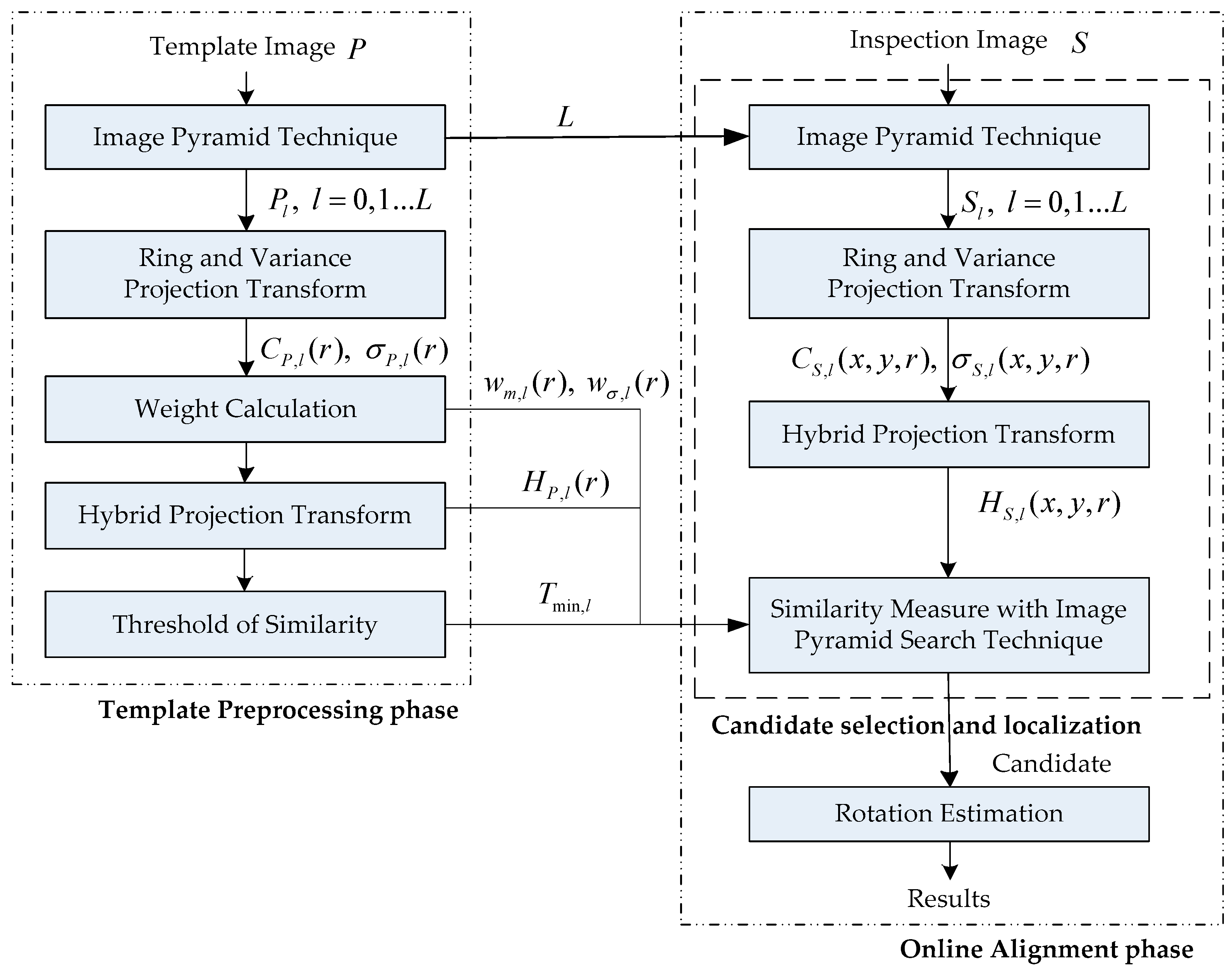
2. Architecture of the Proposed Method
3. Candidate Selection and Localization
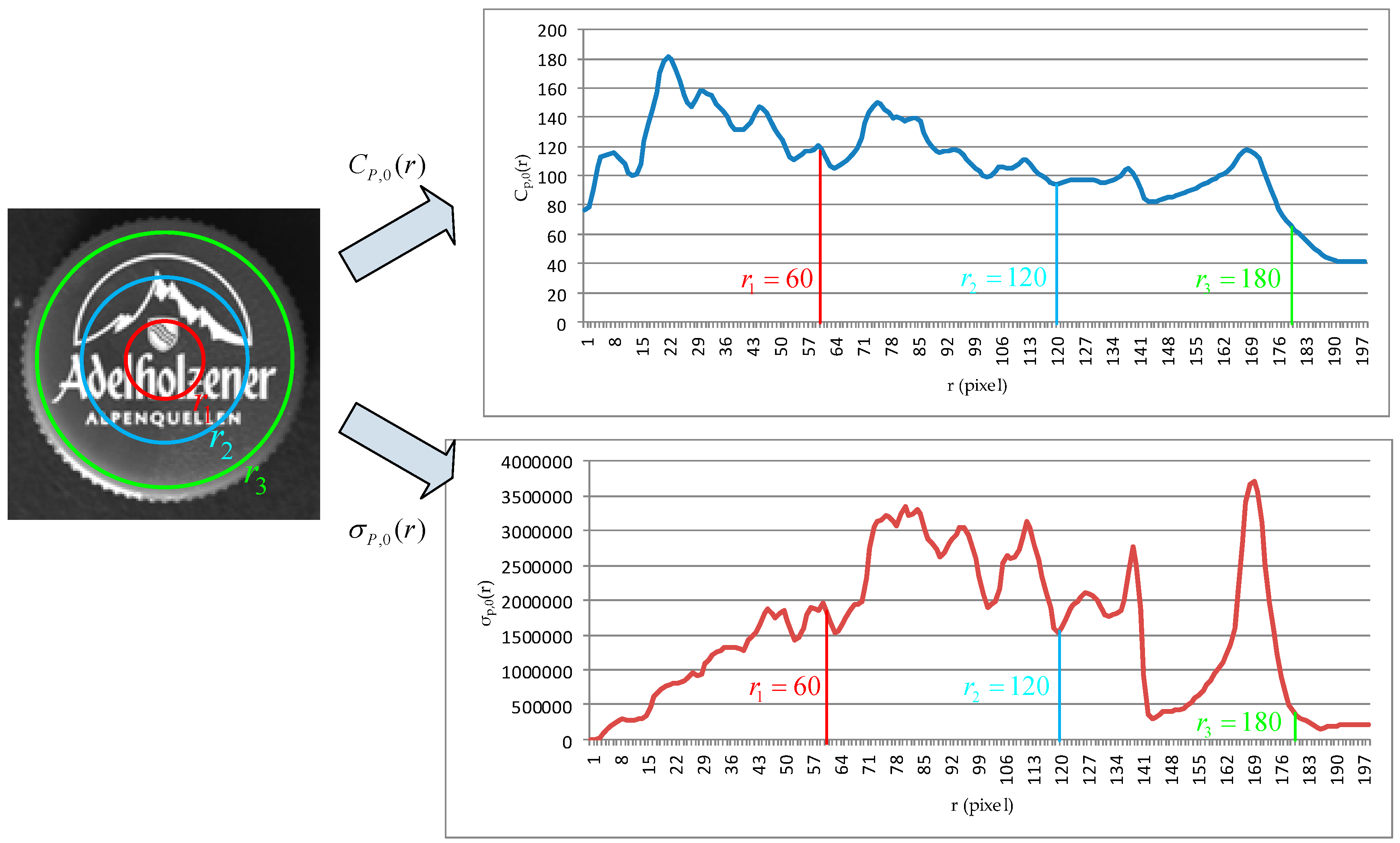
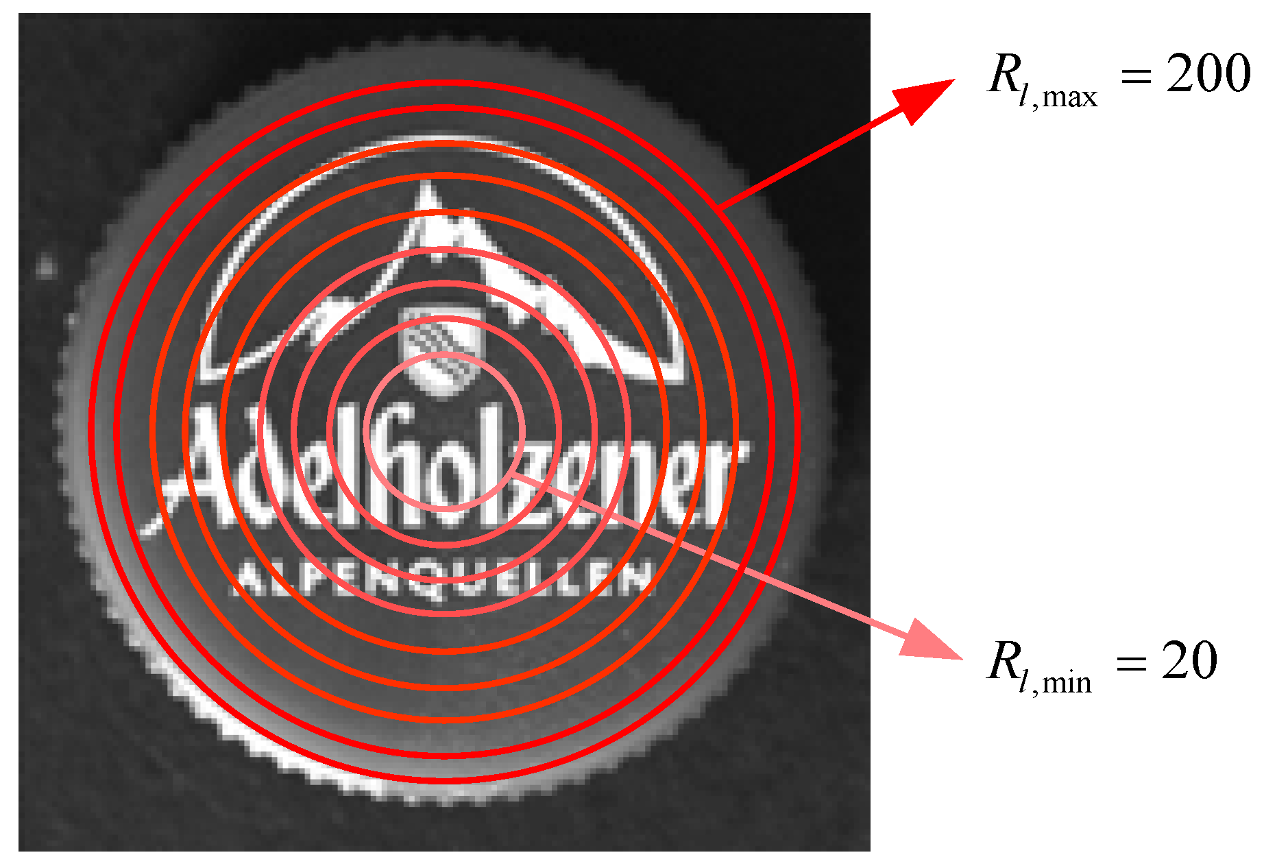
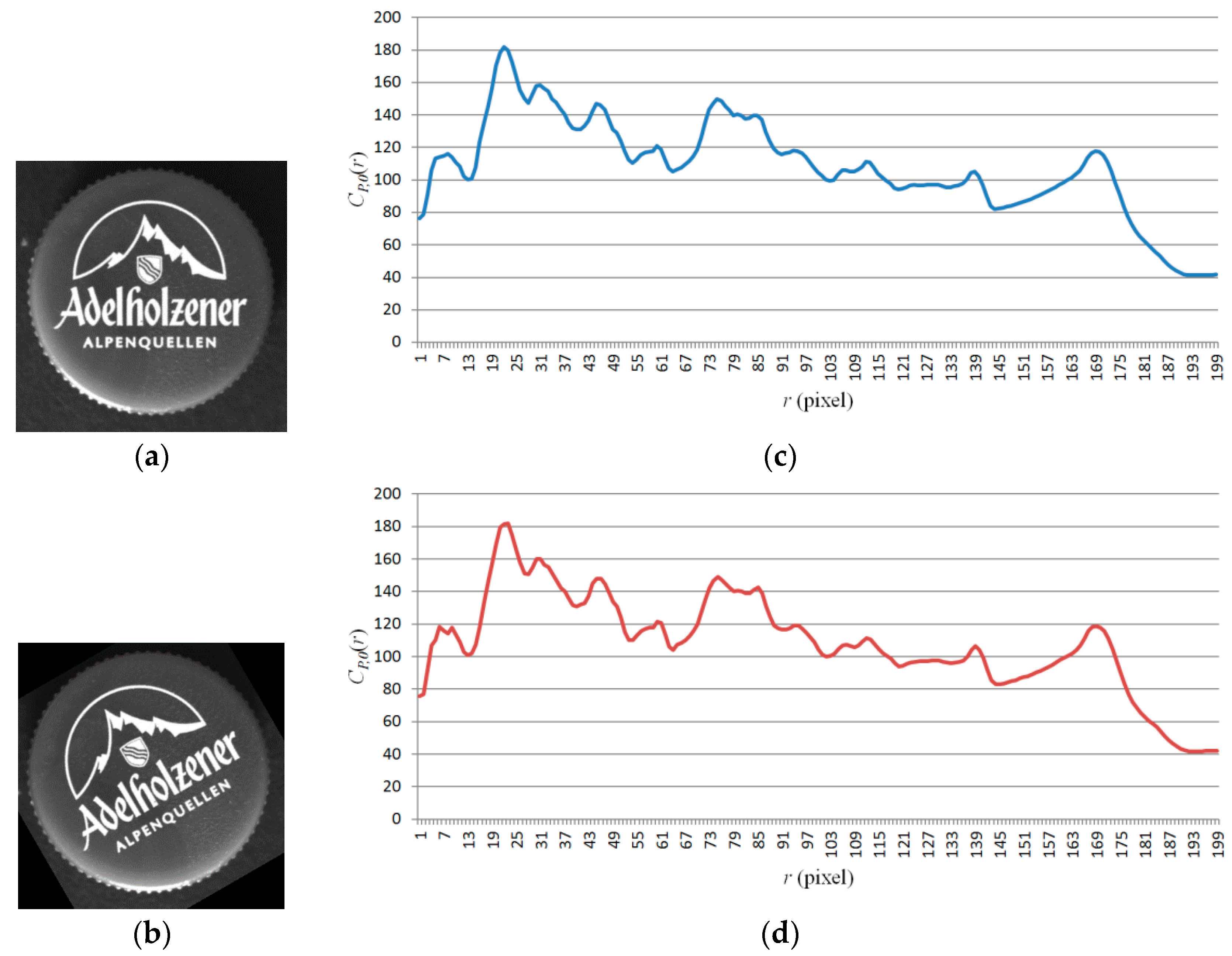
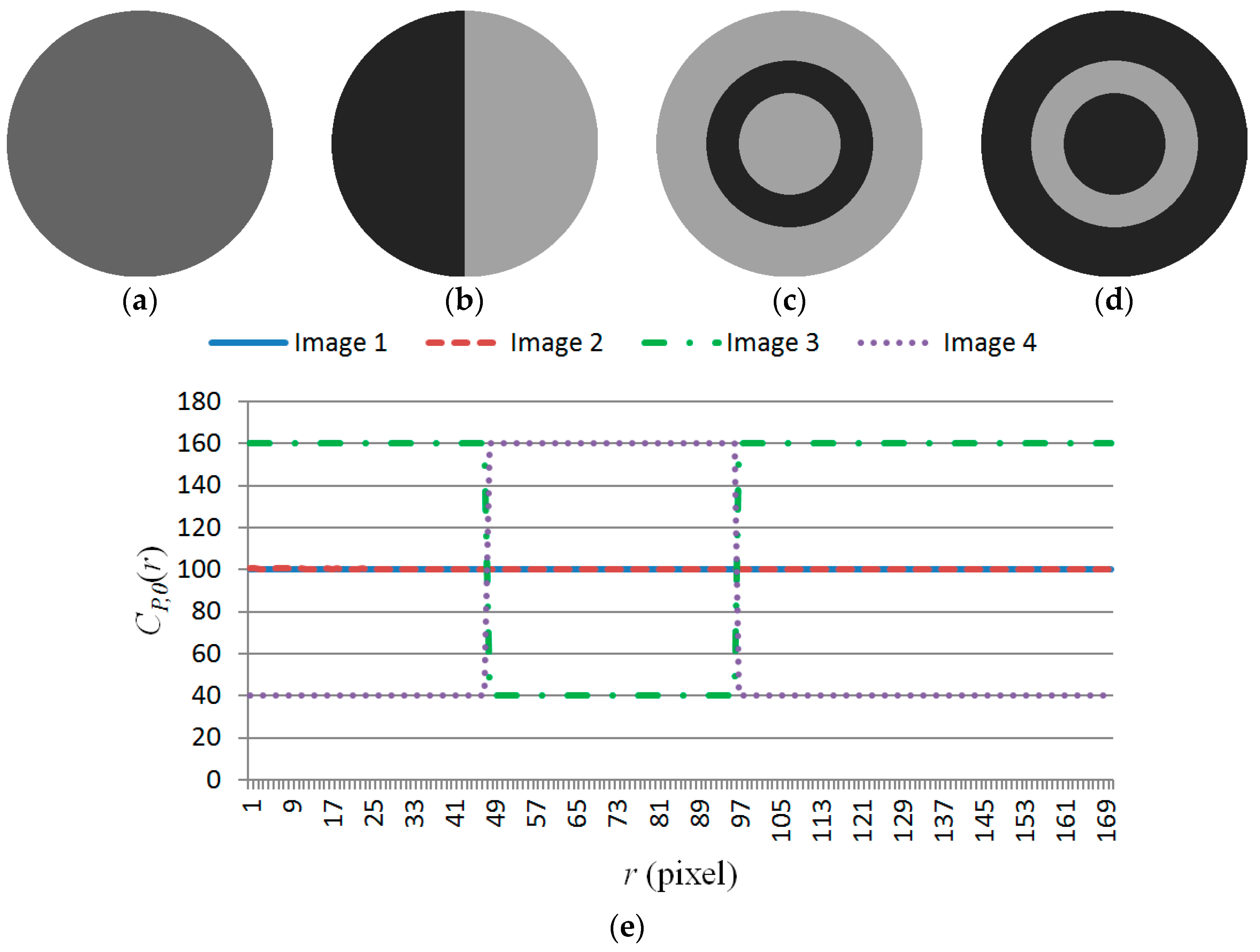
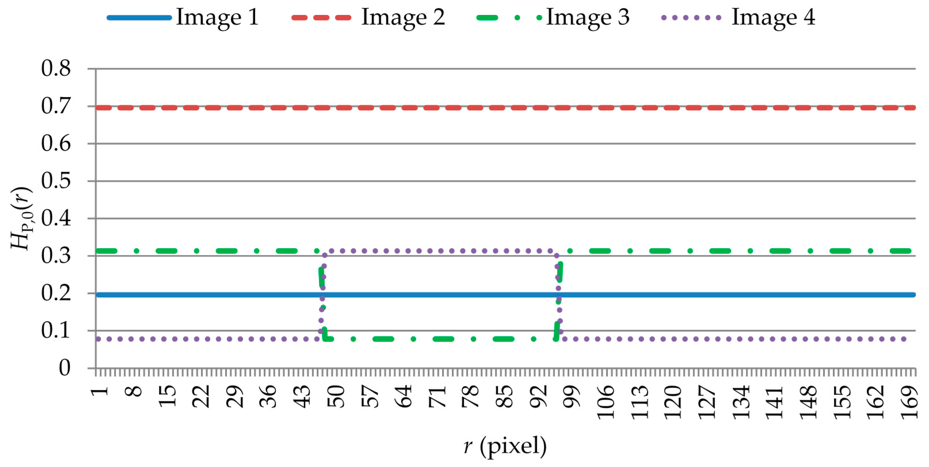
3.1. Ring-Projection Transformation
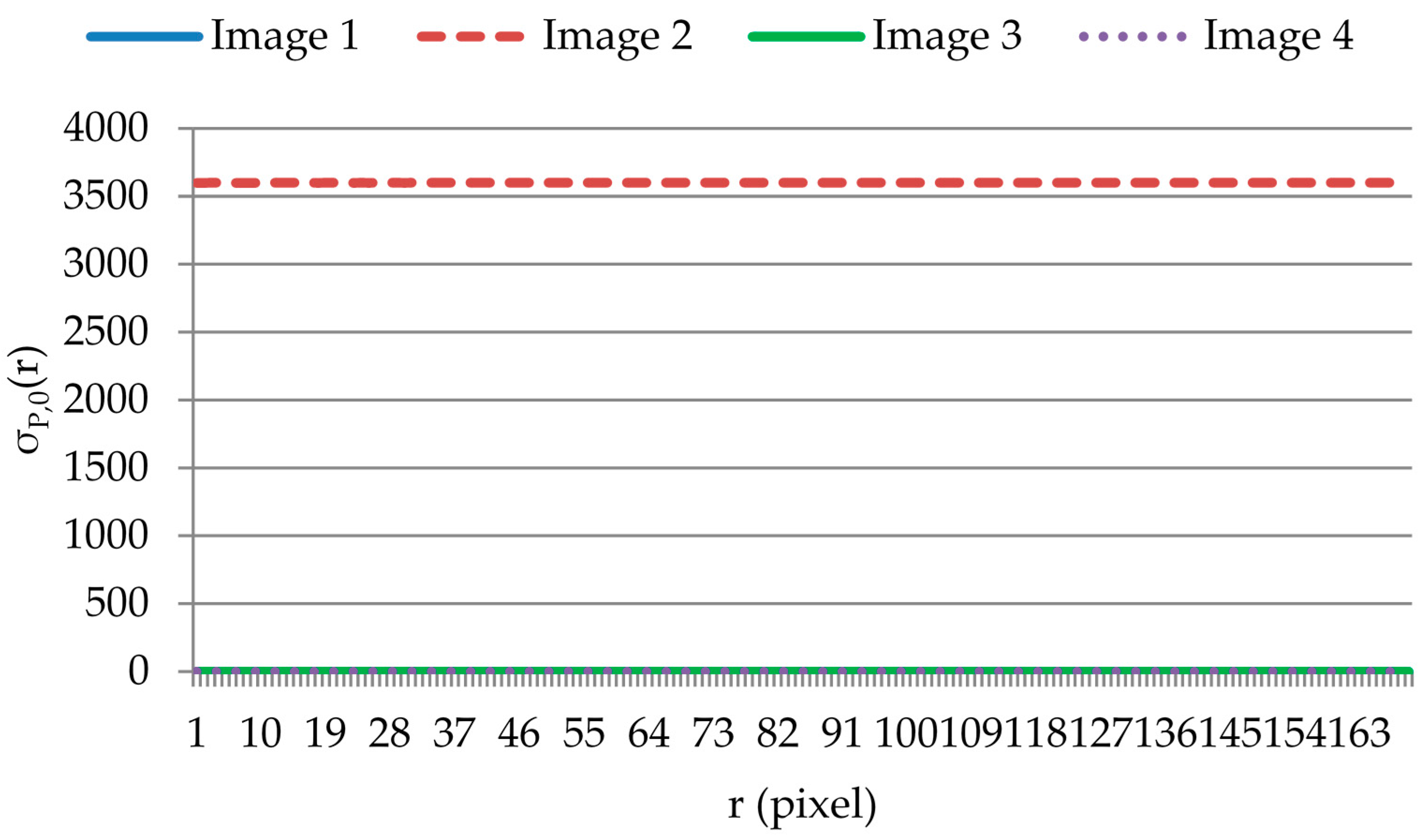
3.2. Robust Features
3.3. Similarity Measurement
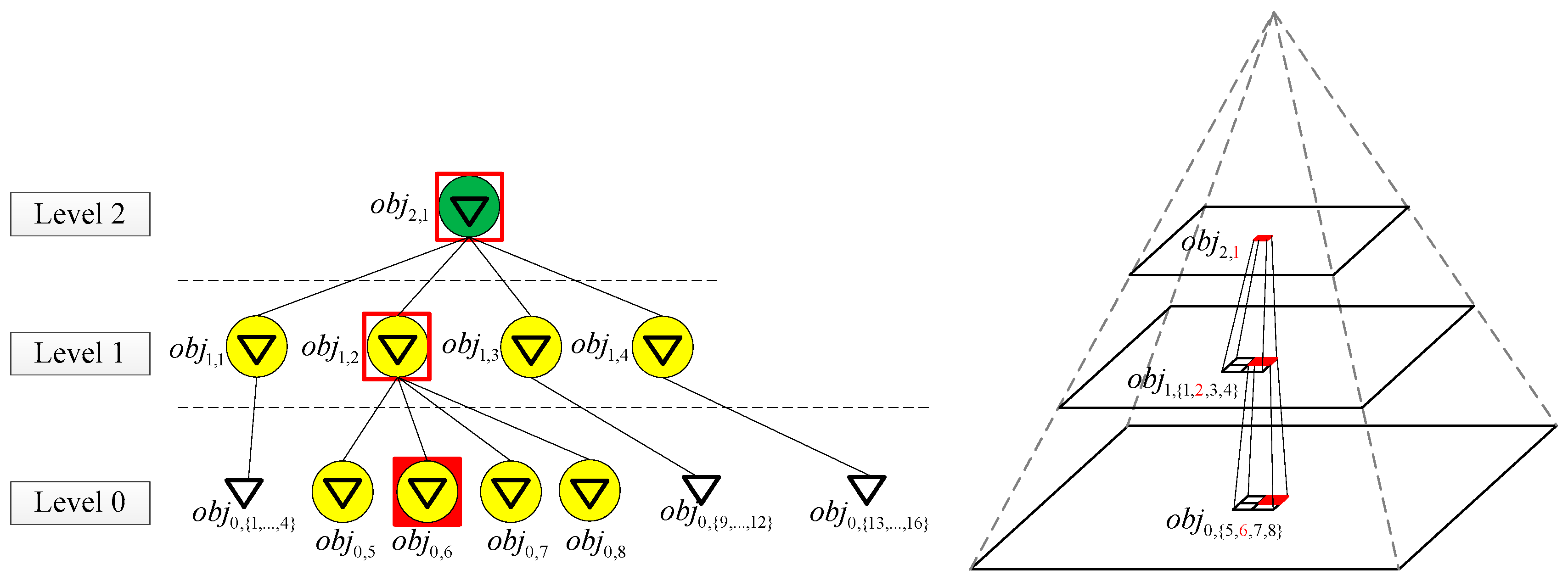
3.4. Image Pyramid Search Technique
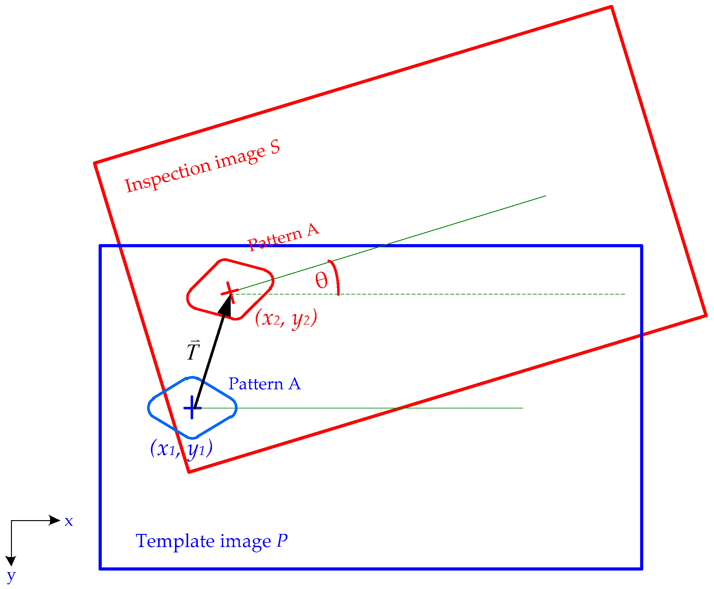
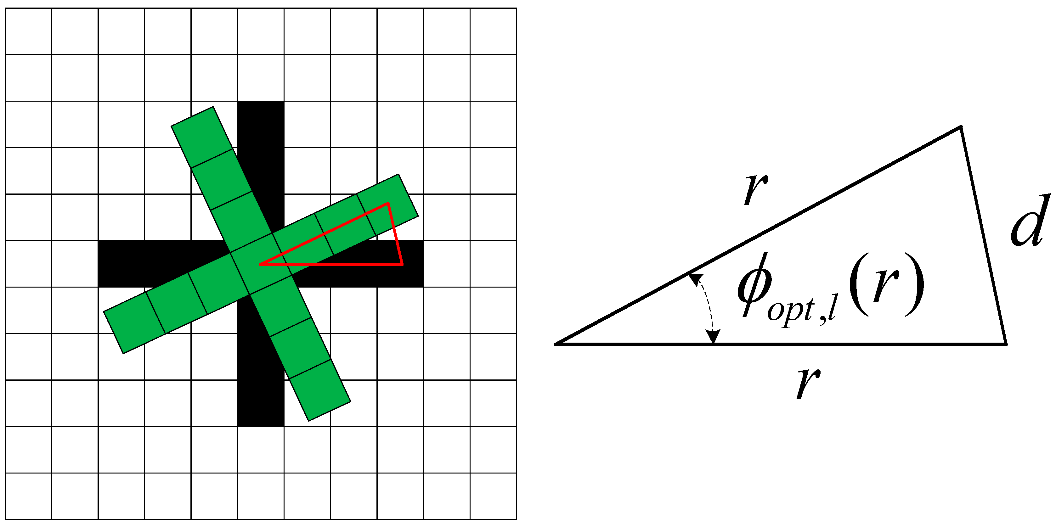
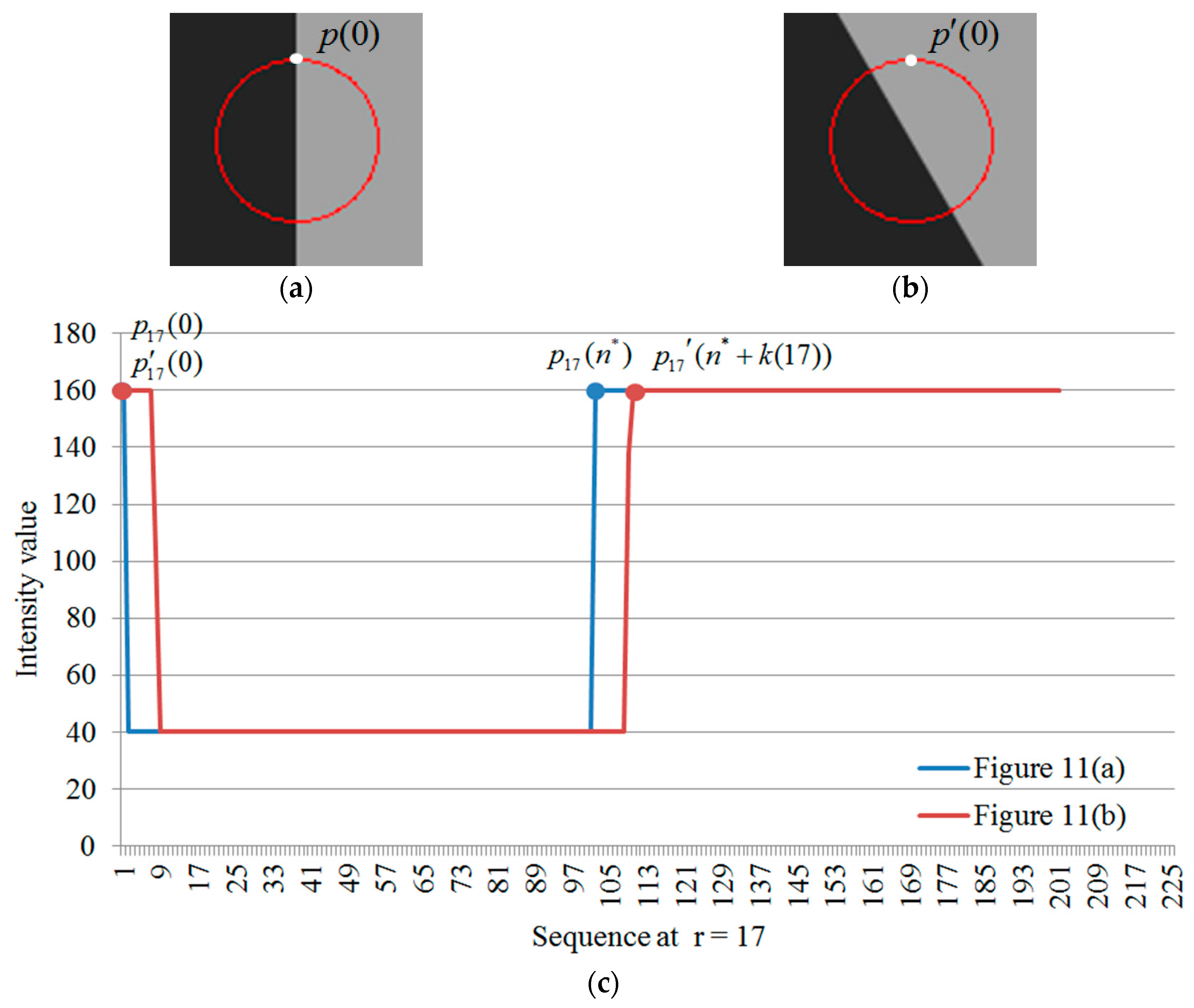
4. Estimation of the Rotation
5. Implementation of the Proposed Method
5.1. Template Preprocessing Phase
- Step 1:
- The template image P is input specified manually.
- Step 2:
- The multi-resolution template image is constructed, where , l represents several image pyramid levels and L is the maximum image pyramid level.
- Step 3:
- Ring-projection transform is used to determine ring-projection values within different image pyramid levels, where .
- Step 4:
- After the ring-projection transform process, the variance-project values for each image pyramid level are determined through variance-project transform, where .
- Step 5:
- The hybrid-projection values for each image pyramid level are determined using ring-projection values , variance-projection values , and the corresponding weighting coefficients for the ring projection and variance projection . The weighting coefficients, and , are calculated by image entropy.
- Step 6:
- An appropriate threshold of similarity, , for different inspection conditions is identified. The levels of the image pyramid, weighting coefficients, hybrid projection values, and threshold are used for the online-alignment phase of the image pyramid technique, and the similarity measure with the image pyramid search technique, respectively.
5.2. Online Alignment Phase
- Step 1:
- A multi-resolution inspection image is constructed, where , and L corresponds to the maximum image pyramid level in the template preprocessing phase.
- Step 2:
- The search block initializes at location (x = 0, y = 0) in the highest inspection image pyramid level. This image is the same size as the template image on the highest image pyramid level.
- Step 3:
- Ring- and variance-projection transform are used to determine the ring-projection values and variance-projection values from the search block at location (x, y) on image pyramid level l.
- Step 4:
- The hybrid-projection values on image pyramid level l are obtained using , and the weighting coefficients, and , which are calculated in the template preprocessing phase.
- Step 5:
- When estimating the similarity coefficient between the template image and search block on image pyramid level l, if the similarity coefficient exceeds the pre-defined threshold for similarity, the location (x, y) is stored in the candidate list.
- Step 6:
- The search block in the inspection image is moved and Steps 3–6 are repeated until the similarity coefficient in the inspection image is computed for all locations.
6. Experimental Results
6.1. Rotation Estimation
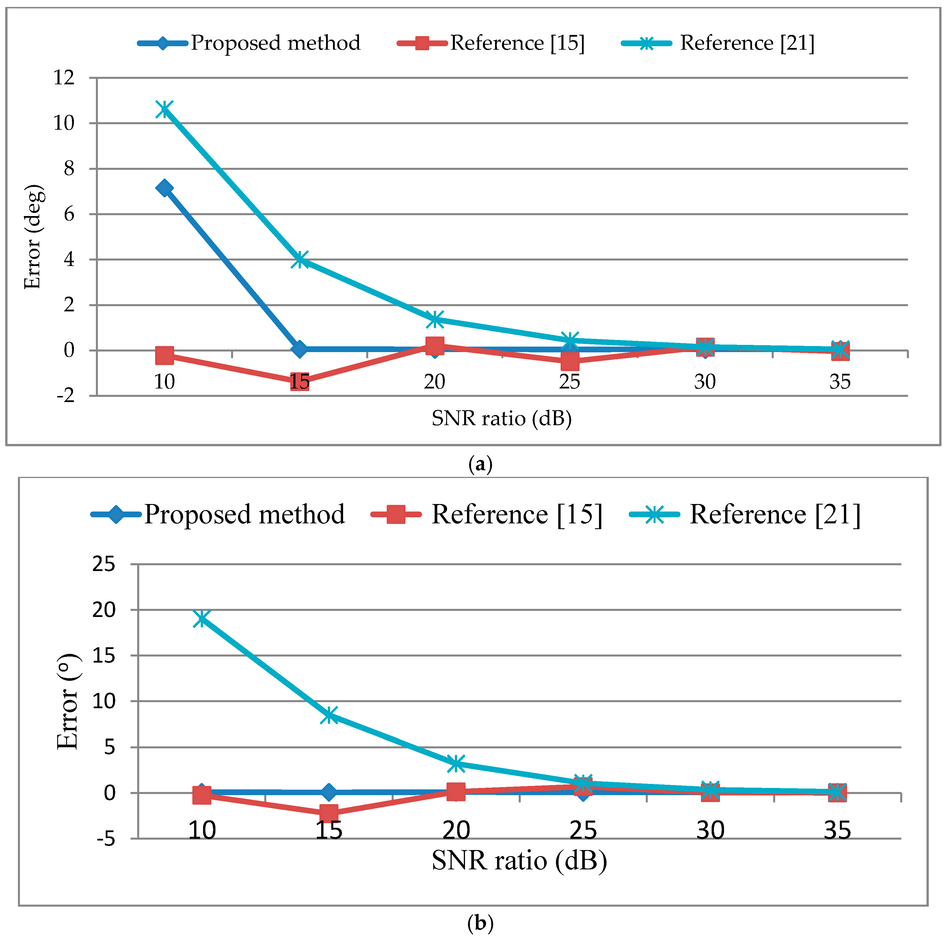
6.2. Performance on Images with Added Noise
6.3. Weighting Influence in Candidate Selection and Localization
6.4. Computational Performance in Real Captured PCB Images
7. Conclusions
Acknowledgments
Author Contributions
Conflicts of Interest
References
- Zitová, B.; Flusser, J. Image registration methods: A survey. Image Vis. Comput. 2003, 21, 977–1000. [Google Scholar] [CrossRef]
- Huttenlocher, D.P.; Klanderman, G.A.; Rucklidge, W.J. Comparing images using the hausdorff distance. IEEE Trans. Pattern Anal. Mach. Intell. 1993, 15, 850–863. [Google Scholar] [CrossRef]
- Huttenlocher, D.P.; Lilien, R.H.; Olson, C.F. View-based recognition using an eigenspace approximation to the hausdorff measure. IEEE Trans. Pattern Anal. Mach. Intell. 1999, 21, 951–955. [Google Scholar] [CrossRef]
- Kwon, O.-K.; Sim, D.-G.; Park, R.-H. Robust hausdorff distance matching algorithms using pyramidal structures. Pattern Recogn. 2001, 34, 2005–2013. [Google Scholar] [CrossRef]
- Chen, C.-J.; Lai, S.-H.; Liu, S.-W.; Ku, T.; Yeh, S.Y. Optical PCB inspection system based on hausdorff distance. In Proceedings of SPIE 5679, Machine Vision Applications in Industrial Inspection XIII, 53, San Jose, CA, USA, 17 January 2005; pp. 53–61.
- Lowe, D.G. Distinctive image features from scale-invariant keypoints. Int. J. Comput. Vis. 2004, 60, 91–110. [Google Scholar] [CrossRef]
- Mikolajczyk, K.; Schmid, C. A performance evaluation of local descriptors. IEEE Trans. Pattern Anal. Mach. Intell. 2005, 27, 1615–1630. [Google Scholar] [CrossRef] [PubMed]
- Khotanzad, A.; Hong, Y.H. Invariant image recognition by zernike moments. IEEE Trans. Pattern Anal. Mach. Intell. 1990, 12, 489–497. [Google Scholar] [CrossRef]
- Mondal, T.; Mourya, G.K. An accelerated approach of template matching for rotation, scale and illumination invariance. In Control, Computation and Information Systems; Springer: Berlin Heidelberg, Germany, 2011; pp. 121–128. [Google Scholar]
- Ullah, F.; Kaneko, S.I. Using orientation codes for rotation-invariant template matching. Pattern Recogn. 2004, 37, 201–209. [Google Scholar] [CrossRef]
- Marimon, D.; Ebrahimi, T. Efficient rotation-discriminative template matching. In Progress in Pattern Recognition, Image Analysis and Applications; Springer: New York, NY, USA, 2007; pp. 221–230. [Google Scholar]
- Tang, Y.Y.; Cheng, H.D.; Suen, C.Y. Transformation-ring-projection (TRP) algorithm and its VLSI implementation. Int. J. Pattern Recogn. Artif. Intell. 1991, 5, 25–56. [Google Scholar] [CrossRef]
- Tsai, D.-M.; Chiang, C.-H. Rotation-invariant pattern matching using wavelet decomposition. Pattern Recogn. Lett. 2002, 23, 191–201. [Google Scholar] [CrossRef]
- Choi, M.-S.; Kim, W.-Y. A novel two stage template matching method for rotation and illumination invariance. Pattern Recogn. 2002, 35, 119–129. [Google Scholar] [CrossRef]
- Tsai, D.-M.; Tsai, Y.-H. Rotation-invariant pattern matching with color ring-projection. Pattern Recogn. 2002, 35, 131–141. [Google Scholar] [CrossRef]
- Lee, W.-C.; Chen, C.-H. A fast template matching method with rotation invariance by combining the circular projection transform process and bounded partial correlation. IEEE Signal Process. Lett. 2012, 19, 737–740. [Google Scholar]
- Lee, W.-C.; Chen, C.-H. A fast template matching method for rotation invariance using two-stage process. In Proceedings of the Fifth International Conference on Intelligent Information Hiding and Multimedia Signal Processing (IIH-MSP 2009), Kyoto, Japan, 12–14 September 2009; pp. 9–12.
- Kim, H.; Araújo, S. Grayscale template-matching invariant to rotation, scale, translation, brightness and contrast. In Advances in Image and Video Technology; Mery, D., Rueda, L., Eds.; Springer: Berlin Heidelberg, Germany, 2007; Volume 4872, pp. 100–113. [Google Scholar]
- Tanimoto, S.L. Template matching in pyramids. Comput. Graph. Image Process. 1981, 16, 356–369. [Google Scholar] [CrossRef]
- Feng, G.C.; Yuen, P.C. Variance projection function and its application to eye detection for human face recognition. Pattern Recogn. Lett. 1998, 19, 899–906. [Google Scholar] [CrossRef]
- Sassanapitak, S.; Kaewtrakulpong, P. An efficient translation-rotation template matching using pre-computed scores of rotated templates. In Proceedings of the 6th International Conference on Electrical Engineering/Electronics, Computer, Telecommunications and Information Technology (ECTI-CON 2009), Pattaya, Chonburi, Thailand, 6–9 May 2009; pp. 1040–1043.


| Category | Features | Approaches | Disadvantages |
|---|---|---|---|
| Feature-based | Edge maps | Hausdorff distance | Inaccurate feature extraction |
| Interest point | Feature correspondence | ||
| Invariant descriptors | Zernike moment | ||
| Orientation code | Dissimilarity measurement | ||
| Area-based | Image templates | Cross correlation | Excessive computation time |
| Ring-projection |
| Case | Performance Index | Proposed Method | [15] | [21] |
|---|---|---|---|---|
| Figure 12a | Er_m () | 0.023 | 0.565 | 62.352 |
| Er_std () | 0.020 | 0.376 | 48.950 | |
| Er_max () | 0.086 | 1.390 | 174.422 | |
| Figure 12b | Er_m () | 0.010 | 1.004 | 90.306 |
| Er_std () | 0.007 | 0.447 | 52.024 | |
| Er_max () | 0.026 | 1.914 | 174.422 | |
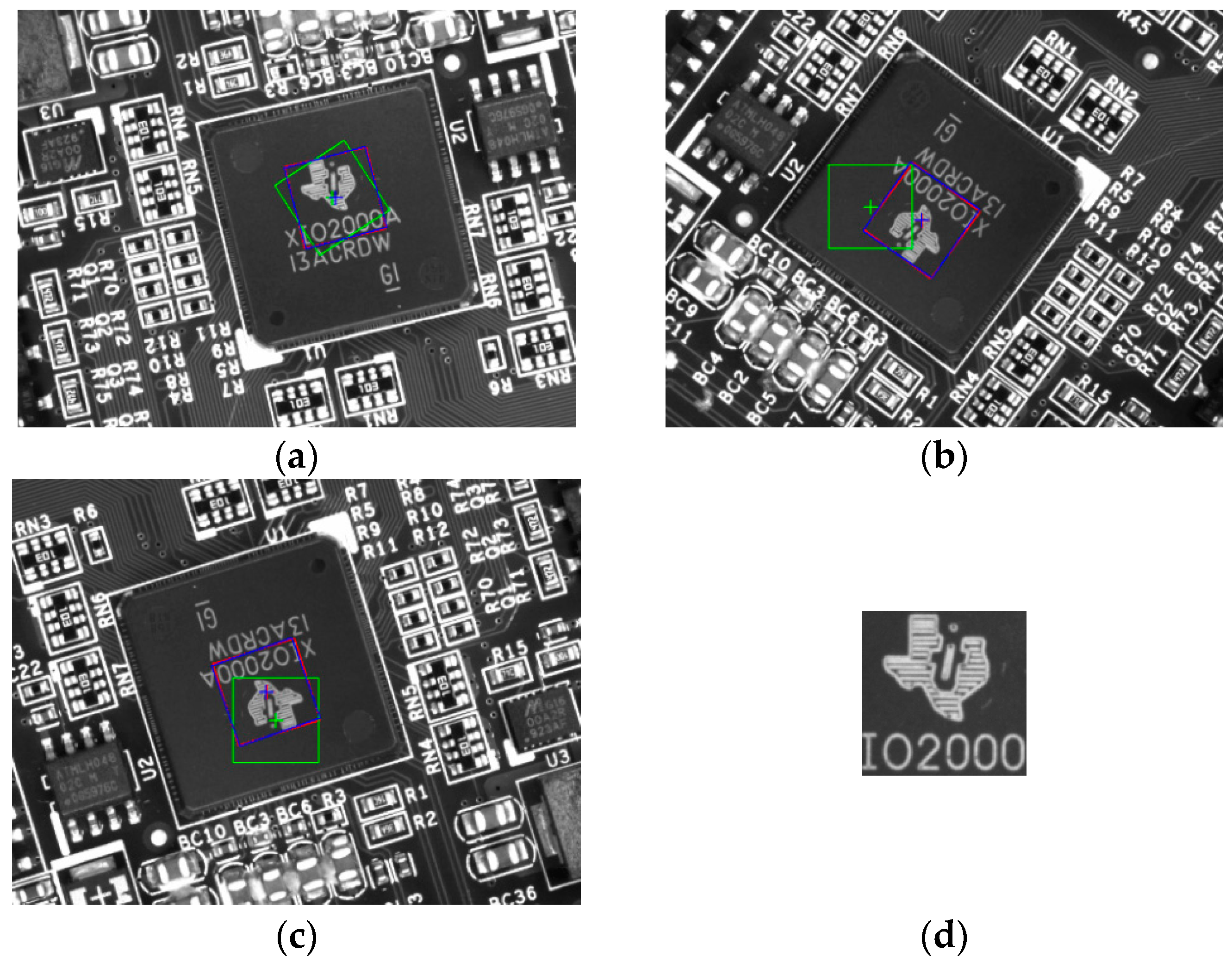
| Figure 12c | Er_m () | 0.036 | 0.488 | 94.930 |
| Er_std () | 0.027 | 0.393 | 47.098 | |
| Er_max () | 0.102 | 1.607 | 174.422 |
| SNR Ratio (dB) | Translation Error (pixel) | ||||||
|---|---|---|---|---|---|---|---|
| 10 | 15 | 20 | 25 | 30 | 35 | ||
| Figure 13a | Proposed method | 0 | 0 | 0 | 0 | 0 | 0 |
| [15] | 0 | 1 | 0 | 0 | 0 | 0 | |
| [21] | 0 | 0 | 0 | 0 | 0 | 0 | |
| Figure 13b | Proposed method | 0 | 0 | 0 | 0 | 0 | 0 |
| [15] | 1.414 | 1 | 0 | 0 | 0 | 0 | |
| [21] | 0 | 0 | 0 | 0 | 0 | 0 | |
| Errors | Figure 15a | Figure 15b | |||||||
|---|---|---|---|---|---|---|---|---|---|
| Translation (pixel) | Rotation () | Translation (pixel) | Rotation () | ||||||
| Methods | Et_m | Et_std | Er_m | Er_std | Et_m | Et_std | Er_m | Er_std | |
| Proposed method | 0 | 0 | 0.004 | 0.001 | 0.17 | 0.37 | 0.92 | 2.02 | |
| = 0.3, = 0.7 | 166.88 | 80.69 | 205.23 | 15.22 | 0.33 | 0.47 | 6.27 | 9.03 | |
| = 0.5, = 0.5 | 160.91 | 11.02 | 241.88 | 9.92 | 0.33 | 0.47 | 6.27 | 9.03 | |
| = 0.7, = 0.3 | 184.49 | 83.11 | 149.39 | 22.44 | 0.33 | 0.47 | 6.27 | 9.03 | |
| Time | Average Execution Time (s) | ||||
|---|---|---|---|---|---|
| Methods | Figure 16 | Figure 17 | Figure 18 | Figure 19 | |
| Pyramid levels = 2 | |||||
| Proposed method | 0.316 | 0.124 | 0.126 | 0.322 | |
| [15] | 0.302 | 0.143 | 0.147 | 0.337 | |
| [21] | 0.057 | 0.03 | 0.031 | 0.062 | |
| Pyramid levels = 1 | |||||
| Proposed method | 1.721 | 0.766 | 0.765 | 1.731 | |
| [15] | 3.701 | 1.393 | 1.401 | 3.842 | |
| [21] | 0.755 | 0.364 | 0.366 | 0.767 | |
| Pyramid levels = 0 (without image pyramid search technique) | |||||
| Proposed method | 19.5 | 8.318 | 8.329 | 21.183 | |
| [15] | 30.458 | 14.85 | 14.465 | 32.172 | |
| [21] | 11.526 | 5.694 | 5.737 | 11.526 | |
© 2016 by the authors; licensee MDPI, Basel, Switzerland. This article is an open access article distributed under the terms and conditions of the Creative Commons Attribution (CC-BY) license (http://creativecommons.org/licenses/by/4.0/).
Share and Cite
Chen, C.-S.; Huang, C.-L. A Novel Image Alignment Algorithm Based on Rotation-Discriminating Ring-Shifted Projection for Automatic Optical Inspection. Appl. Sci. 2016, 6, 140. https://0-doi-org.brum.beds.ac.uk/10.3390/app6050140
Chen C-S, Huang C-L. A Novel Image Alignment Algorithm Based on Rotation-Discriminating Ring-Shifted Projection for Automatic Optical Inspection. Applied Sciences. 2016; 6(5):140. https://0-doi-org.brum.beds.ac.uk/10.3390/app6050140
Chicago/Turabian StyleChen, Chin-Sheng, and Chien-Liang Huang. 2016. "A Novel Image Alignment Algorithm Based on Rotation-Discriminating Ring-Shifted Projection for Automatic Optical Inspection" Applied Sciences 6, no. 5: 140. https://0-doi-org.brum.beds.ac.uk/10.3390/app6050140