Wearable Plasma Pads for Biomedical Applications

1
Department of Electrical and Biological Physics, Kwangwoon University, 20 Kwangwoon-Ro, Nowon Wallgye, Seoul 01897, Korea
2
Institute of Biomaterials, Kwangwoon University, 20 Kwangwoon-Ro, Nowon Wallgye, Seoul 01897, Korea
*
Authors to whom correspondence should be addressed.
†
These authors contributed equally to this work.
Appl. Sci. 2017, 7(12), 1308; https://0-doi-org.brum.beds.ac.uk/10.3390/app7121308
Submission received: 20 November 2017
/
Revised: 7 December 2017
/
Accepted: 14 December 2017
/
Published: 17 December 2017
(This article belongs to the Special Issue Smart Environment and Healthcare)
Abstract
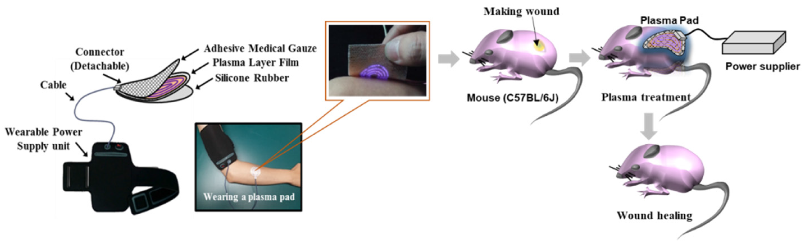
:A plasma pad that can be attached to human skin was developed for aesthetic and dermatological treatment. A polyimide film was used for the dielectric layer of the flexible pad, and high-voltage and ground electrodes were placed on the film surface. Medical gauze covered the ground electrodes and was placed facing the skin to act as a spacer; thus, the plasma floated between the gauze and ground electrodes. In vitro and in vivo biocompatibility tests of the pad showed no cytotoxicity to normal cells and no irritation of mouse skin. Antibacterial activity was shown against Staphylococcus aureus and clinical isolates of methicillin-resistant S. aureus. Furthermore, skin wound healing with increased hair growth resulting from increased exogenous nitric oxide and capillary tube formation induced by the plasma pad was also confirmed in vivo. The present study suggests that this flexible and wearable plasma pad can be used for biomedical applications such as treatment of wounds and bacterial infections.
1. Introduction
Non-thermal atmospheric-pressure plasmas (NAPPs) have been studied for potential applications in dermatology and wound healing [1,2,3,4,5,6]. Plasma components such as ultraviolet (UV) rays, electric current (EC), reactive oxygen species (ROS), and reactive nitrogen species (RNS) are involved in skin treatment.
In the most recent review papers [1,7,8,9,10], plasma sources for cell and tissue research have been introduced. At least three different NAPP sources have been developed for biomedical applications [11,12,13,14]. Direct plasma sources—primarily dielectric barrier discharge (DBD) technology—use the human body as a counter electrode [6,15]. Indirect plasma sources generate plasma between two electrodes within a delivery device and the active components created by the plasma are transported to the target area [16,17,18,19,20,21]. These indirect delivery devices can vary from thin plasma needles to plasma jets and large torches, with different arrangements of electrodes. A recent approach uses the so-called hybrid plasma source, which combines the benefits of both of the above techniques and enables large and flexible plasma designs. Thus far, the plasma sources used for medical purposes have been based on both direct and indirect approaches. Future trends seem to be shifting toward hybrid plasmas, as these enable large and flexible designs.
In the early stage of floating electrode DBD (FE-DBD) plasma generation, a high voltage (10–30 kV) with a low frequency (200 Hz–1 kHz) is applied to an electrode protected by a 1-mm-thick quartz plate as a dielectric barrier [2,19]. Technical (operating voltage) parameters for DBD sources developed at the Leibniz Institute for Plasma Science and Technology (INP Greifswald) are 10 kV at 20 kHz for surface DBD in ambient air [7]. High-voltage (10–30 kV) non-thermal plasma discharge generation in ambient air to treat living animals and humans requires high-level safety precautions. Safety and guaranteed non-injurious regimens are essential in plasma medicine applications.
Our laboratory developed two types of FE-DBD devices [18]. One uses a 1-mm-thick quartz plate and the other uses a copper wire coated with 1-mm-thick foam rubber for insulation against high voltage. The applied voltage is reduced to the range of 2–3 kV at a higher frequency of 40–60 kHz using a direct current to alternative current (DC-AC) inverter. Further development of the FE-DBD involves a reduced operating voltage. The other parameter involved in voltage reduction is dielectric barrier thickness. A thin film of polyimide can reduce thickness by replacing the solid dielectric plate, which is fragile. In this study of hybrid-DBD plasma, the operating voltage was reduced to 1 kV at a frequency of 50 kHz using a flexible 125-µm-thick polyimide film. The lower voltage enables development of a miniaturized wearable power supply with a DC-AC inverter.
For the last two decades, the focus of biomedical plasma research has been on plasma jets and DBD devices. Plasma jets have been developed in pencil structures, while DBD devices comprising a finite surface area have been produced in plane structures [3,16,17,18,19]. Both devices are utilized for direct skin treatments by physicians and other healthcare professionals; however, these devices require prolonged treatment. For example, in the case of atopic eczema, itching decreases after a 4 h plasma treatment, or after applications of several minutes per day for 30 days [3]. Long-term plasma treatment is required for wound healing and treatment of skin diseases. It is also important to note that these devices can only cover a limited area in a single treatment. However, because they are not limited by treatment time and the size of the treatment area, DBDs integrated in an adhesive device for application on human extremities have been proposed [20,21,22].
In this study, a plasma pad was introduced as another hybrid-DBD plasma treatment method, whereby the restrictions on treatment time and size of the treated area are eliminated. A flexible, wearable plasma pad of various sizes can be applied to human skin; therefore, it was expected that the proposed pad could be used as an effective treatment option at various sites, thereby reducing both time and spatial restrictions. Here, a plasma pad system, as well as the power system and spectroscopic plasma emissions, is described. The biocompatibility of the plasma pad and the effect of plasma treatment on wound healing and antibacterial activity were tested.
2. Experimental Methods
2.1. Fabrication and Characterization of a Plasma Pad System
2.1.1. Fabrication of the Plasma Pad
For the dielectric layer of the plasma pad, a commercial polyimide film (Kapton® film, DuPont, Wilmington, DE, USA) was selected, with a thickness ranging from several tens to hundreds of µm. Kapton film has good electrical and physical characteristics, including a thermal resistance up to +400 °C, high chemical resistance, and a high breakdown voltage exceeding 6 kV for a film thickness of 120 µm, with a field strength of 5 × 10⁵ V/cm [23]. For a hybrid-DBD plasma pad, the high-voltage electrode and the ground electrode were fabricated on the upper and lower surfaces of the 120-µm-thick polyimide film of the plasma pad. The pad is electrically safe because the high-voltage film surface is covered with silicone rubber for insulation, while the cold plasma that is generated on the ground electrode surface is in contact with the skin and medical gauze covers the film surface of the ground electrode. To attach the pad to the skin, adhesive paste is applied around the periphery of the gauze, except in the area covering the ground electrode.
2.1.2. Characteristics of Applied Power
A sinusoidal voltage in the range of 1–2 kV at a frequency of 50 kHz was applied to the high-voltage electrode through a DC-AC inverter. The operating voltage was modulated with the duty ratio of an on-and-off time control as defined by
with an on-time of τ and a modulation period of T = 4 s. For a duty ratio β = 100%, respective voltage and current values measured at the terminal of the inverter were approximately 1.1 kV rms and 5.5 mA rms. The input power to the inverter was Po = 6 W for β = 100% and P = βPo for a variable β.
2.1.3. Measurement Method for Temperature and Ozone Concentration
The temperature of the plasma pad was measured with a thermocouple attached to the gauze on the surface of the plasma pad, and high voltage was applied to measure the temperature change. The temperature was measured for 1 h under both conditions of β = 50% and β = 100%. The ozone concentration in the plasma pad was measured using ozone detectors (Detector Tube No. 18 L, GASTEC, Ayase, Japan). The measuring distance between the plasma pad and the ozone detector was 10 cm or 20 cm, and the duty ratio of the applied power was 25%, 50%, 75%, or 100%.
2.1.4. Optical Emission Spectroscopy of the Plasma Pad
The emitted surface light from the plasma pad was collected by a spectroscopic diagnostic system, composed of a collimating lens pair, optical fiber (QP400-2-SR), and spectrophotometer (HR4000CG-UV-NIR, Ocean Optics, Largo, FL, USA) with a linear charge-coupled device (CCD) detector array. Emission spectra were measured over a wide wavelength range of 200–1100 nm. The spectral focal length was 101 mm, and the best spectral resolution was 0.75 nm (Full Width Half Max). This system was calibrated with deuterium and mercury lamps. The measured data were integrated over 1 s or more. The recorded data were observed using Origin 8.5 software.
2.2. In Vitro and In Vito Biocompatibilty Testing of the Plasma Pad
For in vitro biocompatibility tests, cytotoxicity was assessed using green fluorescent protein (GFP)-transfected keratinocytes (HaCaT cells) and fibroblasts (L-929 cells), as previously described [24,25,26]. Briefly, the GFP-transfected HaCaT and L-929 cells were maintained in high-glucose Dulbecco’s modified Eagle’s medium (DMEM) with 10% fetal bovine serum (FBS) and 1% antibiotic solution. Each cell line was seeded on cover glasses (ϕ 12 mm) in 24-well plates (Coster Corp., Bethesda, MD, USA) at 1.5 × 10⁵ cells/mL and incubated at 37 °C in 5% CO2 for 24 h. After incubation, the cover glasses were transferred into a non-coated 35 mm dish with 2 mL of DMEM media and the plasma pad was placed about 1 to 2 mm distant from the media in the dish. Each cell line on the cover glass was exposed to plasma by treating the media surface for 0 min, 1 min, 3 min, 5 min, and 10 min and the cover glass was transferred into a 24-well plate and incubated at 37 °C in 5% CO2 for another 24 h. Cell viability was calculated using the absorbance value of each well at 450 nm after incubation with a Cell Counting Kit-8 (CCK-8) solution (Dojindo Laboratories, Kumamoto, Japan). To confirm morphological changes, each cell was examined with an imaging reader (Cytation 3; BioTek Instruments, Inc., Winooski, VT, USA). The data shown for biocompatibility in this study were obtained from two independent experiments (sample number n = 4) and were expressed as mean ± standard deviation (SD) for quantitative data. Statistical comparisons were performed with a Student’s t-test, and P < 0.05 was considered statistically significant.
To evaluate in vivo biocompatibility, a skin irritation test was conducted on hairless mice using a method described in the ISO 10993-10 [27]. Briefly, 10 healthy hairless mice were used for in vivo experiments and were divided into 2 groups. Group 1 served as the control, and Group 2 was treated with plasma for 10 min. After plasma treatment, signs of edema and/or erythema in each mouse were checked at 24 h and 48 h, and any responses in the plasma-treated group were also evaluated according to the method in the ISO 10993-10. Histological analysis was also performed after staining with hematoxylin and eosin (H&E).
2.3. Detection of Nitric Oxide Generated by the Plasma Pad
In order to detect exogenous nitric oxide (NO), an absorption-based Griess reagent method was used to determine total amounts of generated by the plasma pad. Griess reaction solutions and processes were prepared as in a previous report [28]. Briefly, 2 samples (1 mL each) of Dulbecco’s phosphate buffered solution (DPBS) and DMEM with 10% FBS were exposed to plasma for different treatment times (0 min, 1 min, 3 min, 5 min, and 10 min). Then, 100 μL of each plasma-treated sample was placed into the 96-well microplate and 100 μL of the two Griess reagents was added to each sample solution. The mixed solutions were left for at least 30 min to terminate this reaction. After mixing, the absorbance was measured at 540 nm using a multimode microplate reader (CYTATION 3, BioTek Instruments, Inc., Winooski, VT, USA). Calibration was performed using a sodium nitrate solution for each measurement.
2.4. Analysis of Capillary Tube Formation with Plasma Treatment
Human dermal microvascular endothelial cells (HDMVECs, Lonza, Walkersville, MD, USA) were purchased from Lonza Japan Ltd. and cultured in endothelial cell-basal medium-2 (EBM-2) supplemented with 2% FBS and endothelial cell growth supplements (Lonza, Walkersville, MD, USA), and a 1% antimycotic solution at 37 °C and 5% CO2. The capillary tube formation study was performed with the HDMVECs between Passages 5 and 6.
For cell differentiation in HDMVECs, each well of a 24-well plate was coated with 180 μL of Matrigel (growth factor reduced type; BD Biosciences, Rockville, MD, USA) and incubated at 37 °C for 30 min to harden the Matrigel in each well. Pre-cultured HDMVECs were plated at 0.3 × 10⁵ cells/mL in non-coated 35 mm dishes with 2 mL of EBM-2 media and the plasma pad was placed as described above. Then, the HDMVECs were also exposed to plasma by treating the media surface for 0 min, 1 min, 3 min, 5 min, and 10 min. The plasma-treated HDMVECs were transferred into the Matrigel-coated 24-well plate and incubated at 37 °C to form capillary tubes. After incubation for 8 h, each well was examined with an automated live cell imager (LIONHEART FX; BioTek Instruments, Inc., Winooski, VT, USA) to confirm the formation of new capillary tubes from HDMVECs by plasma treatment.
2.5. In Vivo Wound Healing Experiment
To confirm the in vivo wound healing effect of the plasma pad, an animal experiment was conducted using a full-thickness excisional wound model as previously described [26,29,30,31]. Briefly, 16 healthy male mice (C57BL/6J, Charles River Corp. Inc., Barcelona, Spain) were divided into 2 groups and the mice in each group were bred in individual cages. To induce full-thickness excisional wounds, the skin was disinfected with povidone-iodine and 70% (v/v) ethanol and a sterile biopsy punch (8 mm in diameter) was used to create a full-thickness excisional wound. Then, each wound site was carefully splinted using a silicone-splinting ring (12 mm inner diameter and 20 mm outer diameter) and the plasma pad was attached on the silicone ring. After plasma treatment for 10 min, the wounds in each mouse were dressed with a transparent wound dressing (Tegaderm film, 3M Corp.) and the dressing was changed every other day. The negative control mice were treated with PBS only. The wound sites were observed using a stereomicroscope (SZX16, Olympus, Tokyo, Japan) every other day and histological analysis of each skin sample was performed after 21 days with H&E staining to evaluate the wound healing effect of the plasma treatment.
2.6. Evaluation of Antibacterial Activity Using Plasma Treatment
To confirm the antibacterial activity of the plasma pads, Staphylococcus aureus (S. aureus ATCC 14458) and methicillin-resistant S. aureus (MRSA), isolated from patients at the Yonsei Medical Center in Seoul [26], were used. S. aureus was grown on plate count agar (PCA, Becton, Dickinson and Company, Sparks, MD, USA) at 35 °C for 24 h and MRSA was grown on Brain Heart Infusion agar (BHIA, Becton, Dickinson and Company, Sparks, MD, USA) at 35 °C for 24 h. Pre-cultured bacterial cells were suspended at 1 × 10⁶–1 × 10⁷ colony forming units (CFU)/mL in nutrient broth for (S. aureus) and BHI broth for MRSA. The bacterial cells were inoculated into 24-well plates after 10-fold dilution to yield 1 × 10⁵–1 × 10⁶ CFU/mL and were incubated at 35 °C after plasma treatment for 0 min, 1 min, 3 min, 5 min, and 10 min. After incubation for 24 h, the bacterial cells were serially diluted by 10-fold increments (1 × 101 to 1 × 10⁷) and inoculated into PCA or BHIA to confirm cell viability. Bacterial cell viability was determined by counting the CFU of each bacterial type, and the antibacterial activity was defined as a >3-log decrease in CFU/mL.
3. Results and Discussion
3.1. Description of the Plasma Pad
The plasma pad introduced in this paper was produced in the form of a wearable device with a flexible thin-film plasma sheet and an electric power unit. Figure 1 shows a schematic of the overall concept of the plasma pad system, including the wearable power-supply unit stored in a band-type pocket. Electrical power is supplied to the pad through a cable with a connector, and the connector is detachable for pad disposal. After the system has been charged with the secondary battery of the power-supply unit, it can be used in a wireless form without external power; therefore, the patient can move freely while wearing the plasma pad system. Although plasma is generated in the voids of the gauze space between the skin and the film surface, the plasma pad has good electrical safety. In addition, it is protected from low temperature thermal damage as the film surface constantly maintains a temperature below 40 °C.
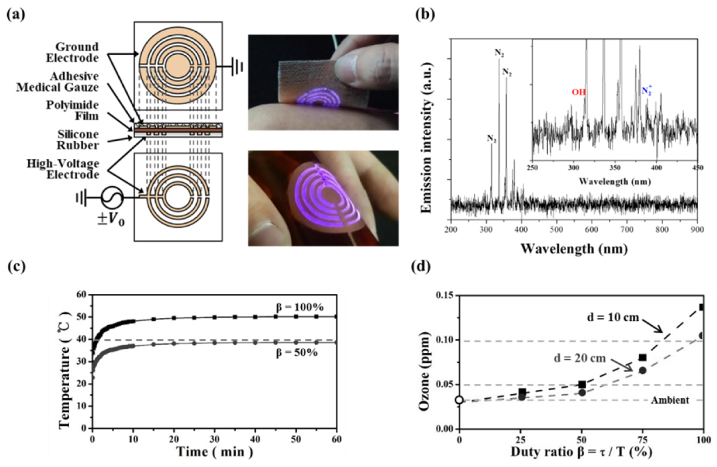
A schematic of the plasma film layers and the discharge of the flexible plasma pad are shown in Figure 2a. A sinusoidal voltage of 50 kHz and 1.1 kV rms is applied to the high-voltage electrode. The cold plasma is readily generated even on a curved flexible surface, as shown in Figure 2a, and no electrical problems are evident when the flexible pad is attached to the skin.
To confirm the formation of the ROS and RNS generated in the discharge, the plasma pad surface light was analyzed by optical emission spectroscopy in the wavelength range of 200–900 nm (Figure 2b). The identification of these emission lines was performed according to previous reports [32,33]. The strongest emission peaks were the nitrogen lines at 316 nm, 337 nm, and 358 nm. It should be noted that emission lines from OH (309 nm) and (391 nm) appeared, but their intensities were very weak. These emission spectra indicate that the processed chemical and physical reaction produced various ROS such as NO, OH, and via the plasma pad.
Figure 2c shows the variation of temperature inside the plasma pad versus the operating time under the same operating conditions of β = 100% and β = 50. The temperature was measured using a thermocouple inside the pad attached to the skin. Temperature saturating occurred at 50 °C for β = 100% and at 38.6 °C for β = 50% after 10 min. During a long-run test of several hours for stability and safety at an operating voltage of 1.1 kV, failures, such as thermal deformation of the film, were not observed, but slight erosion-staining due to plasma on the ground electrode was noted. Concerns about safety and failure due to aerial ozone or thermal heat can be readily reduced through use of the power control for voltage modulation.
An important issue could be the adjustability of aerial ozone to maintain an allowable concentration below 0.08 ppm and an ozone odor detection threshold below 0.03 ppm [34,35]. Figure 2d shows the assessment of ozone concentration in aerial space over the plasma pad with voltage modulation for power control during plasma generation. Figure 2d shows ozone concentration versus duty ratio at distances of d = 10 cm and d = 20 cm. When β = 100%, the ozone concentration is slightly >0.10 ppm. When β < 50%, the concentration is <0.05 ppm, nearly below odor detection level. Figure 2d shows the possibility of ozone control in the plasma pad. Even if the concentration over the plasma surface was 0.10 ppm at a distance d = 10 cm with β = 100%, the measured level was <0.05 ppm with the pad attached to the skin.
In this study, the use of medical gauze is a distinctive feature of the plasma pad. While the pad is attached to skin, plasma is generated in the gauze between the pad and the skin. The medical gauze plays the role of a spacer, securing a void space for the generation of plasma. Another advantage is that medical gauze can be used for various skin care purposes by applying medication as a gel or ointment, which will not prevent plasma ignition in the gauze. As shown in Figure 3, plasma generation between the pad and skin is visually verified by attaching the plasma pad to a glass plate rather than to human skin. Figure 3a shows the layers comprising the pad. Because the discharge is not visible when the pad is attached to skin, the pad is placed on the glass plate to visually verify the discharge underneath the glass plate. Figure 3b shows a photograph taken from over the glass plate. The photograph shows that the plasma was generated in the gauze space, even with the pad attached to the glass plate. The ring pattern of plasma reflects the pattern of the ground electrode placed on the polyimide film as shown in Figure 2a.
3.2. Biocompatibilty of the Plasma Pad
For biomedical applications of the plasma pad, tests recommended by the International Organization for Standardization-10993 (ISO-10993) are essential for assessing safety. Therefore, we performed in vitro and in vivo biocompatibility experiments on the plasma pad using two kinds of skin cells and hairless mice.
As shown in Figure 4a,b, there was no cytotoxicity in GFP-transfected HaCaT cells or mouse skin fibroblasts (L-929 cells), and morphological changes were also not observed with plasma treatment, although cell viability was slightly decreased compared to that of controls due to plasma treatment.
None of the plasma treatments triggered skin irritation at any site, nor did plasma treatment induce intracutaneous damage, as shown in Figure 4c. Additionally, no symptoms related to skin tissue toxicity or abnormal behaviors, such as convulsions or prostration, were observed, even after treatment for 10 min. The results demonstrate that treatment with a plasma pad is minimally toxic to skin cells, HaCaT and L-929 cells, and mouse skin, and the plasma pad is biocompatible for use in skin treatment.
3.3. Exogenous Nitric Oxide and Capillary Tube Formation in Hdmvecs Induced by the Plasma Pad
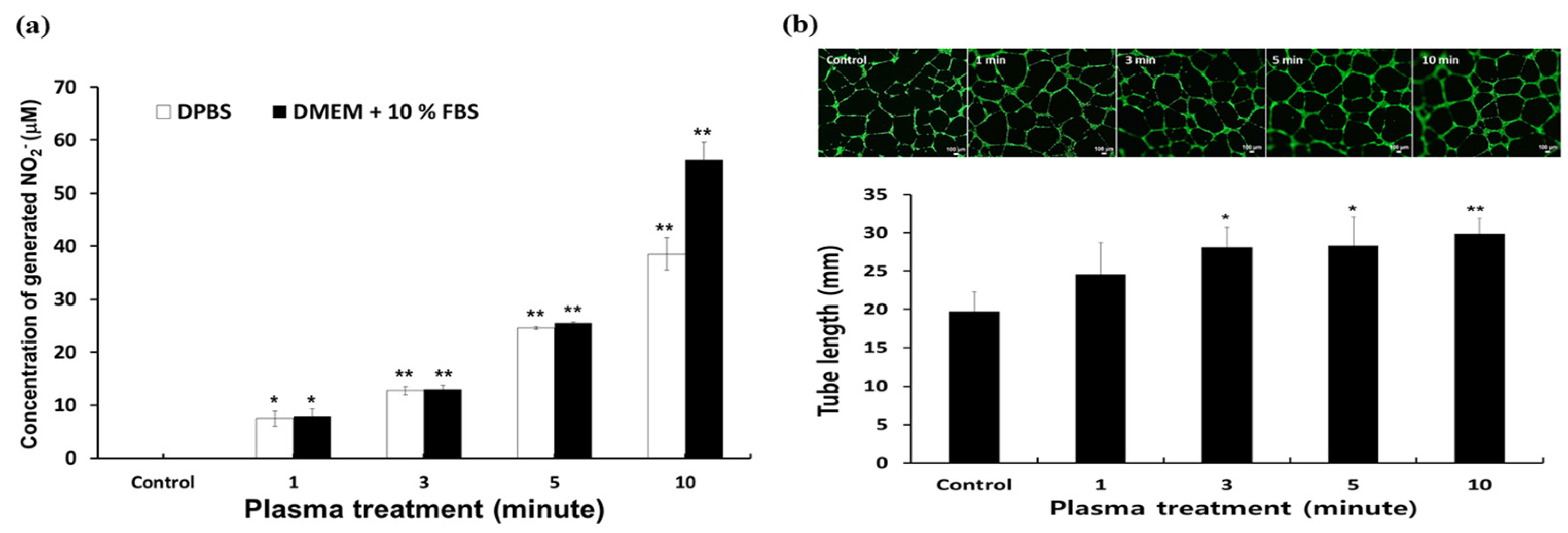
Plasma is known to catalyze and regulate biochemical activities and cellular responses such as proliferation, differentiation, and cell death or apoptosis [36]. The responses may be due to the ROS and RNS generated by non-thermal plasma [37]. Among the various reactive species, NO can modulate angiogenesis, resulting in the promotion of wound healing. Therefore, we analyzed exogenous generated from plasma by using Griess reagents. As shown in Figure 5a, plasma treatment significantly increased exogenous in both DPBS and cell culture media in a time-dependent manner, and the amount of generated reached a maximum 60 mM with 10 min of plasma treatment. This indirectly indicates that the NO generated from plasma plays a key role in vascularization and wound healing.
Generally, vascularization or angiogenesis plays a key role in both wound healing and tissue recovery. Non-thermal plasma recently emerged as a useful method in biomedical applications due to the ROS and RNS produced. With exogenous NO data, angiogenesis activity was also confirmed with plasma treatment. Although angiogenesis is a very complex process, capillary tube formation by endothelial cells is a key step [38,39].
To evaluate the potential for angiogenesis with plasma treatment, a capillary tube formation assay was performed using HDMVECs on Matrigel for 8 h. As shown in Figure 5b, the HDMVECs treated with plasma formed well-defined capillary tubes with enhanced alignment and organization in a time-dependent manner; moreover, the total length of the capillary tubes also increased with plasma treatment, while the negative control HDMVECs formed randomly short and disconnected capillary tubes. This result demonstrates that plasma treatment of HDMVECs may have potential for enhancement of vascularization in the field of tissue engineering
3.4. Wound Healing Effect of the Plasma Pad
To evaluate the in vivo wound healing effect of the plasma pad, treatment was applied at each site after full-thickness excisional wounds were made on mouse back skin; wound closure in each group was observed using a stereomicroscope and the wound area was observed for 21 days after treatment.
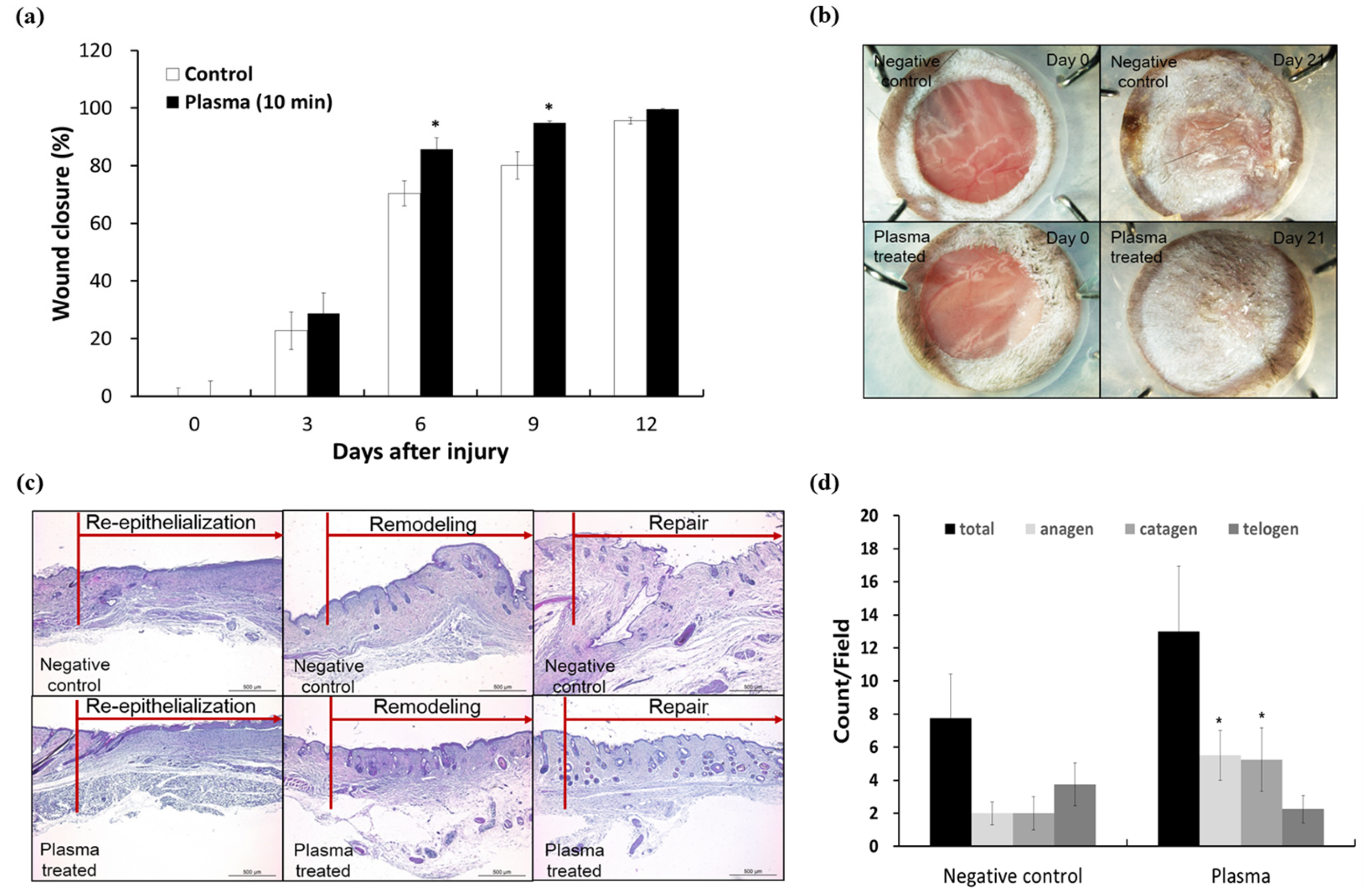
Plasma treatment significantly enhanced the rate of wound closure at Days 6 and 9 compared to that in negative controls (Figure 6a). The rate of wound closure in the plasma-treated group reached about 85.8% and 94.8%, respectively (* P < 0.05) compared to that in the control group (72% and 84%). This might be due to rapid re-epithelialization resulting in the promotion of cell proliferation and/or migration, thereby facilitating wound healing. Additionally, we assume that the increased exogenous NO in the wound area and around tissues promoted angiogenesis and enhanced cellular growth for wound healing. This is supported by several previous studies reporting that NO resulted in angiogenesis triggering cellular growth and differentiation in a wound model [38,39,40,41].
As shown in Figure 6b, the wounded skin fully recovered without any contraction or crusting in plasma-treated mice, whereas some crusting was found in the negative control group at Day 21.
To confirm wound healing efficacy, recovery was evaluated by using the rate of skin re-epithelialization, remodeling, and repair in each slide sample after staining with H&E. The rate of wound repair in the plasma-treated group was 1.3-fold higher than that in the negative control group, calculated as 12.5% in negative controls and 16.7% in the plasma-treated group. This indicates that plasma treatment induced accelerated wound repair at Day 21 compared to the controls. Histological analysis also exhibited the same result as shown in Figure 6c. The histological images of skin treated with plasma showed re-epithelialization with thick epidermis and increased dermal fibroblasts, resulting in dense dermal fiber, remodeling with some skin adnexa including hair follicles and dense dermal fibroblast, and complete wound repair with skin adnexa and increased hair follicles. Hair follicles in anagen and catagen stages were significantly increased compared with the control group, as shown in Figure 6d. On the other hand, compared with the plasma-treated group, the negative control group showed re-epithelialization of thin epidermis, skin remodeling with fewer dermal fibroblasts, less deposition of collagen, and wound repair with fewer total hair follicles and increased telogen-stage follicles.
The overall rate of wound healing in the plasma-treated group was enhanced in comparison with that in negative controls. These results indicate that remodeling of skin tissue through re-epithelialization is faster in the plasma-treated group than in the negative control group, resulting in an increased rate of wound repair.
3.5. Antibacterial Activity of the Plasma Pad
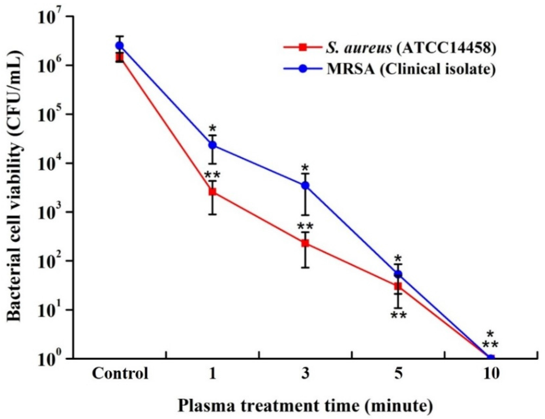
The plasma pad antibacterial properties were evaluated using quantitative and qualitative methods that involved counting the number of CFUs and performing inhibition zone assays after plasma treatment, as shown in Figure 7. The antibacterial activity using a quantitative method shows a similar trend to the one shown for the treatment time-dependent antibacterial effect in the qualitative analysis and the plasma pads showed significant killing efficiency toward S. aureus as well as clinical MRSA isolates. The strong antibacterial effects of the plasma pad were also observed in qualitative images. These results indicate that plasma pads can also be used for skin disinfection.
Overall, these results suggest that the biocompatible plasma pad, which causes no cytotoxicity or skin irritation, has a wound healing effect and antibacterial activity against S. aureus and drug-resistant bacteria, such as MRSA, indicating great potential as a method of skin treatment.
4. Conclusions
A wearable hybrid-DBD plasma pad with a wearable power supply was developed. Unlike earlier plasma jets or DBD devices, this wearable plasma pad offers a variety of applications and convenience in terms of treatment area and time.
The flexible thin-film plasma pad was fabricated with a polyimide film as a dielectric layer in a DBD, where two electrodes were formulated on each surface. Protection from electrical hazard was ensured because the high-voltage electrode was covered with an insulation layer, and the plasma was generated on a ground electrode that was covered with medical gauze facing the skin. A distinctive feature of the proposed plasma pad was the containment of the plasma in the gauze space, even when the pad was attached to human skin. During operation at approximately 1 kV, stability and safety were ensured, as electrical and thermal damage to the skin and aerial ozone or thermal heat could be readily reduced through power modulation.
From in vitro and in vivo biocompatibility tests, the potential of the plasma pad for biomedical applications was confirmed, with no cytotoxicity for normal cells and no irritation of mouse skin. Skin wound healing with hair growth was also observed after in vivo plasma treatment. Moreover, the activity of the plasma pad against two bacteria present in normal or damaged skin, including MRSA, was demonstrated.
Future research will be conducted to confirm the actual treatment effect of plasma in the form of a patch, bandage, socks, and cap.
Acknowledgments
This work was supported in part by the Kwangwoon University under a Research Grant in 2017 and by a grant provided from the National Research Foundation of Korea (NRF-2017R1A2B4012590 and NRF-2015M3A9E2066855).
Author Contributions
Guangsup Cho conceived and designed the experiments; Junggil Kim, Kyong-Hoon Choi, and Bong Joo Park performed the experiments and wrote the manuscript; Yunjung Kim analyzed the data.
Conflicts of Interest
The authors declare no conflict of interest.
References
- Heinlin, J.; Morfill, G.; Landthaler, M.; Stolz, W.; Isbary, G.; Zimmermann, J.L.; Shimizu, T.; Karrer, S. Plasma medicine: Possible applications in dermatology. J. Dtsch. Dermatol. Ges. 2010, 8, 968–976. [Google Scholar] [CrossRef] [PubMed]
- Isbary, G.; Köritzer, J.; Mitra, A.; Li, Y.F.; Shimizu, T.; Schroeder, J.; Schlegel, J.; Morfill, G.E.; Solz, W.; Zimmermann, J.L. Ex vivo human skin experiments for the evaluation of safety of new cold atmospheric plasma devices. Clin. Plasma Med. 2013, 1, 36–44. [Google Scholar] [CrossRef]
- Emmert, S.; Brehmer, F.; Hänßle, H.; Helmke, A.; Mertens, N.; Ahmed, R.; Simon, D.; Wandke, D.; Friedrichs, W.M.; Däschlein, G.; et al. Atmospheric pressure plasma in dermatology: Ulcus treatment and much more. Clin. Plasma Med. 2013, 1, 24–29. [Google Scholar] [CrossRef]
- Kalghatgi, S.U.; Fridman, G.; Fridman, A.; Friedman, G.; Clyne, A.M. Non-Thermal Dielectric Barrier Discharge Plasma Treatment of Endothelial Cells. In Proceedings of the 30th Annual International Conference of the IEEE Engineering in Medicine and Biology Society, Vancouver, BC, Canada, 20–24 August 2008. [Google Scholar]
- Helmke, A.; Hoffmeister, D.; Mertens, N.; Emmert, S.; Schuette, J.; Vioel, W. The acidification of lipid film surfaces by non-thermal DBD at atmospheric pressure in air. New J. Phys. 2009, 11, 115025–115034. [Google Scholar] [CrossRef]
- Fridman, G.; Shereshevsky, A.; Jost, M.M.; Brooks, A.D.; Fridman, A.; Gutsol, A.; Vasilets, V.; Friedman, G. Floating Electrode Dielectric Barrier Discharge Plasma in Air Promoting Apoptotic Behavior in Melanoma Skin Cancer Cell Lines. Plasma Chem. Plasma Process. 2007, 27, 163–176. [Google Scholar] [CrossRef]
- Haertel, B.; von Woedtke, T.; Weltmann, K.-D.; Lindequist, U. Non-Thermal Atmospheric-Pressure Plasma Possible Application in Wound Healing. Biomol. Ther. 2014, 22, 477–490. [Google Scholar] [CrossRef] [PubMed]
- Isbary, G.; Zimmermann, J.L.; Shimizu, T.; Li, Y.-F.; Morfill, G.E.; Thomas, H.M.; Steffes, B.; Heinlin, J.; Karrer, S.; Stolz, W. Non-thermal plasma—More than five years of clinical experience. Clin. Plasma Med. 2013, 1, 19–23. [Google Scholar] [CrossRef]
- Heinlin, J.; Isbary, G.; Stolz, W.; Morfill, G.; Landthaler, M.; Shimizu, T.; Steffes, B.; Nosenko, T.; Zimmermann, J.L.; Karrer, S. Plasma applications in medicine with a special focus on dermatology. J. Eur. Acad. Dermatol. Venereol. 2010, 25, 1–11. [Google Scholar] [CrossRef] [PubMed]
- Tiede, R.; Hirschberg, J.; Daeschlein, G.; von Woedtke, T.; Vioel, W.; Emmert, S. Plasma Applications: A Dermatological View. Contrib. Plasma Phys. 2014, 54, 118–130. [Google Scholar] [CrossRef]
- Weltmann, K.-D.; Brandenburg, R.; von Woedtke, T.; Ehlbeck, J.; Foest, R.; Stieber, M.; Kindel, E. Antimicrobial treatment of heat sensitive products by miniaturized atmospheric pressure plasma jets (APPJs). J. Phys. D Appl. Phys. 2008, 41, 194008. [Google Scholar] [CrossRef]
- Hahnel, M.; von Woedtke, T.; Weltmann, K.-D. Influence of the Air Humidity on the Reduction of Bacillus Spores in a Defined Environment at Atmospheric Pressure Using a Dielectric Barrier Surface Discharge. Plasma Process. Polym. 2010, 7, 244–249. [Google Scholar] [CrossRef]
- Ehlbeck, J.; Schnabel, U.; Polak, M.; Winter, J.; von Woedtke, T.; Brandenburg, R.; von dem Hagen, T.; Weltmann, K.-D. Low temperature atmospheric pressure plasma sources for microbial decontamination. J. Phys. D Appl. Phys. 2011, 44, 013002. [Google Scholar] [CrossRef]
- Wu, Z.; Chen, M.; Li, P.; Zhu, Q.; Wang, J. Dielectric barrier discharge non-thermal micro-plasma for the excitation and emission spectrometric detection of ammonia. Analyst 2011, 136, 2552–2557. [Google Scholar] [CrossRef] [PubMed]
- Fridman, G.; Fridman, G.; Gutsol, A.; Shekhter, A.; Vasilets, V.; Fridman, A. Applied Plasma Medicine. Plasma Process. Polym. 2008, 5, 503–533. [Google Scholar] [CrossRef]
- Shashurin, A.; Keidar, M.; Bronnikov, S.; Jurjus, R.A.; Stepp, M.A. Living tissue under treatment of cold plasma atmospheric jet. Appl. Phys. Lett. 2008, 98, 181501. [Google Scholar] [CrossRef]
- Weltmann, K.-D.; Kindel, E.; Brandenburg, R.; Meyer, C.; Bussiahn, R.; Wilke, C.; von Woedtke, T. Atmospheric Pressure Plasma Jet for Medical Therapy: Plasma Parameters and Risk Estimation. Contrib. Plasma Phys. 2009, 49, 631–640. [Google Scholar] [CrossRef]
- Kim, Y.; Jin, S.; Han, G.; Kwon, G.; Choi, J.; Choi, E.; Uhm, H.; Cho, G. Plasma Apparatuses for Biomedical Applications. IEEE Trans. Plasma Sci. 2015, 43, 944–950. [Google Scholar] [CrossRef]
- Fridman, G.; Peddinghaus, M.; Ayan, H.; Fridman, A.; Balasubramanian, M.; Gutsol, A.; Brooks, A.; Friedman, G. Blood Coagulation and Living Tissue Sterilization by Floating-Electrode Dielectric Barrier Discharge in Air. Plasma Chem. Plasma Process. 2006, 26, 425–442. [Google Scholar] [CrossRef]
- Weltmann, K.-D.; Fricke, K.; Stieber, M.; Brandenburg, R.; von Woedtke, T.; Schnabel, U. New Nonthermal Atmospheric-Pressure Plasma Sources for Decontamination of Human Extremities. IEEE Trans. Plasma Sci. 2012, 40, 2963–2969. [Google Scholar] [CrossRef]
- Von Woedtke, T.; Reuter, S.; Masur, K.; Weltmann, K.-D. Plasmas for medicine. Phys. Rep. 2013, 530, 291–320. [Google Scholar] [CrossRef]
- Weltmann, K.-D.; Polak, M.; Masur, K.; von Woedtke, T.; Winter, J.; Reuter, S. Plasma Processes and Plasma Sources in Medicine. Contrib. Plasma Phys. 2012, 52, 644–654. [Google Scholar] [CrossRef]
- Diaham, S.; Zelmat, S.; Locatelli, M.L.; Dinculescu, S.; Decup, M.; Lebey, T. Dielectric Breakdown of Polyimide Films—Area, Thickness and Temperature Dependence. IEEE Trans. Dielectr. Electr. Insul. 2010, 17, 18–27. [Google Scholar] [CrossRef]
- International Standard ISO 10993-5. Part 5: Tests for In Vitro Cytotoxicity; International Organization for Standardization: Geneva, Switzerland, 2009. [Google Scholar]
- Park, B.J.; Choi, K.H.; Nam, K.C.; Min, J.; Lee, K.D.; Uhm, H.S.; Choi, E.H.; Kim, H.J.; Jung, J.S. Photodynamic Anticancer Activity of CoFe2O4 Nanoparticles Conjugated with Hematoporphyrin. J. Nanosci. Nanotechnol. 2015, 15, 7900–7906. [Google Scholar] [CrossRef] [PubMed]
- Lee, Y.; Choi, K.H.; Park, K.Y.; Lee, J.M.; Park, B.J.; Park, K.D. In situ forming and H2O2-releasing hydrogels for treatment of drug-resistant bacterial infections. ACS Appl. Mater. Interfaces 2017, 9, 16890–16899. [Google Scholar] [CrossRef] [PubMed]
- International Standard ISO 10993-10. Part 10: Tests for Irritation and Skin Sensitization; International Organization for Standardization: Geneva, Switzerland, 2010. [Google Scholar]
- Giustarini, D.; Rossi, R.; Milzani, A.; Dalle-Donne, I. Nitrite and Nitrate Measurement by Griess Reagent in Human Plasma: Evaluation of Interferences and Standardization. Methods Enzymol. 2008, 440, 361–380. [Google Scholar] [CrossRef] [PubMed]
- Wang, X.; Ge, J.; Tredget, E.E.; Wu, Y. The mouse excisional wound splinting model including applications for stem cell transplantation. Nat. Protoc. 2013, 8, 302–309. [Google Scholar] [CrossRef] [PubMed]
- Asai, J.; Takenaka, H.; Kusano, K.F.; Ii, M.; Luedemann, C.; Curry, C.; Eaton, E.; Iwakura, A.; Tsutsumi, Y.; Hamada, H.; et al. Topical sonic hedgehog gene therapy accelerates wound healing in diabetes by enhancing endothelial progenitor cell-mediated microvascular remodeling. Circulation 2006, 113, 2413–2424. [Google Scholar] [CrossRef] [PubMed]
- Luo, J.D.; Wang, Y.Y.; Fu, W.L.; Wu, J.; Chen, A.F. Gene therapy of endothelial nitric oxide synthase and manganese superoxide dismutase restores delayed wound healing in type 1 diabetic mice. Circulation 2004, 110, 2484–2493. [Google Scholar] [CrossRef] [PubMed]
- Kim, S.J.; Joh, H.M.; Chung, T.H. Production of intracellular reactive oxygen species and change of cell viability induced by atmospheric pressure plasma in normal and cancer cells. Appl. Phys. Lett. 2013, 103, 153705. [Google Scholar] [CrossRef]
- Cheng, X.; Murphy, W.; Recek, N.; Yan, D.; Cvelbar, U.; Vesel, A.; Mozetič, M.; Canady, J.; Keidar, M.; Sherman, J.H. Synergistic effect of gold nanoparticles and cold plasma on glioblastoma cancer therapy. J. Phys. D Appl. Phys. 2014, 47, 335402. [Google Scholar] [CrossRef]
- Wilska, S. Ozone. Its Physiological Effects and Analytical Determination in Laboratory Air. Acta Chem. Scand. 1951, 5, 1359–1367. [Google Scholar] [CrossRef]
- Diggle, W.M.; Cage, J.C. The toxicity of ozone in the presence of oxides of nitrogen. Br. J. Ind. Med. 1955, 12, 60–64. [Google Scholar] [CrossRef] [PubMed]
- Graves, D.B. Low temperature plasma biomedicine: A tutorial review. Phys. Plasmas 2014, 21, 080901. [Google Scholar] [CrossRef]
- Niemi, K.; O’Connell, D.; de Oliveira, N.; Joyeux, D.; Nahon, L.; Booth, J.P.; Gans, T. Absolute atomic oxygen and nitrogen densities in radio-frequency driven atmospheric pressure cold plasmas: Synchrotron vacuum ultra-violet high-resolution Fouriertransform absorption measurements. Appl. Phys. Lett. 2013, 103, 034102. [Google Scholar] [CrossRef]
- Lucia, M.; Sandra, D.; Marina, Z. Role of nitric oxide in the modulation of angiogenesis. Curr. Pharm. Des. 2003, 9, 521–530. [Google Scholar] [CrossRef]
- Luo, J.-D.; Chen, A.F. Nitric oxide: A newly discovered function on wound healing. Acta Pharmacol. Sin. 2005, 26, 259–264. [Google Scholar] [CrossRef] [PubMed]
- Zhu, H.; Wei, X.; Bian, K.; Murad, F. Effects of nitric oxide on skin burn wound healing. J. Burn Care Res. 2008, 29, 804–814. [Google Scholar] [CrossRef] [PubMed]
- Stefen, F.; Heiko, K.; Christian, W.; Josef, P. Nitric oxide drives skin repair: Novel functions of an established mediator. Kidney Int. 2002, 61, 882–888. [Google Scholar] [CrossRef]
Figure 1.
Schematic illustration of the wearable plasma pad kit and photographs of the thin-film plasma pad discharge.
Figure 1.
Schematic illustration of the wearable plasma pad kit and photographs of the thin-film plasma pad discharge.

Figure 2.
(a) Schematic illustration of the plasma pad and photographs of the thin-film plasma pad discharge; (b) Optical emission spectroscopy of plasma pad discharge; (c) Variation of temperature measured inside the pad attached to the skin with β = 100% and β = 50% during 1 h operation; (d) Ozone concentration according to the duty ratio at the distances of d = 10 cm and d = 20 cm over the plasma surface.

Figure 3.
(a) Schematic of the plasma pad attached to a glass plate and (b) a photograph of plasma pad discharge under a glass plate.
Figure 3.
(a) Schematic of the plasma pad attached to a glass plate and (b) a photograph of plasma pad discharge under a glass plate.

Figure 4.
In vitro and in vivo biocompatibility of the plasma pad. (a) Quantitative analysis of in vitro cytotoxicity of the plasma pad on GFP-transfected human keratinocytes (HaCaT cells) and mouse fibroblasts (L-929 cells). (n = 4, * P < 0.05 compared to control); (b) Images of plasma-treated GFP-transfected HaCaT cells and L-929 cells. The images are magnified from those inserted in each picture taken with a 4× optical lens. Scale bars are 100 μm; (c) Schematic illustration for evaluating the in vivo skin irritation test using the plasma pad; (d) Photographs and histological images of mouse skin at day 2 post-plasma treatment for 10 min. Scale bars represent 200 μm.

Figure 5.
Exogenous nitric oxide () and in vitro capillary tube formation with plasma treatment. (a) Quantitative analysis of generated by a plasma pad (n = 4, * P < 0.005, ** P < 0.0005 compared to control); (b) Images of capillary tube formation by HDMVECs with plasma treatment and quantitative analysis of capillary tube length (n = 5, * P < 0.005, ** P < 0.0005 compared to control). Scale bars are 100 μm.

Figure 6.
In vivo wound healing effects of plasma pads in the full-thickness excisional wound splinting model. (a) Quantification of the wound closure rate following wounding. (n = 8, * P < 0.05 compared to control); (b) Representative stereomicroscopic images of full-thickness wound sites and wound contraction at Days 0 and 21. Scale bars are 2 mm; (c) Histological images of hematoxylin and eosin (H&E) staining of negative control and plasma-treated skin. Scale bars are 500 μm; (d) Quantitative hair follicle assessment in repaired wound sites. Total and hair follicles at each stage (anagen, catagen, and telogen) were determined after H&E staining (n = 8, * P < 0.05 compared to control).

Figure 7.
Antibacterial activity of the plasma pad. Viable bacterial cells were counted after 24 h post-plasma treatment. Differences of P < 0.05 were considered statistically significant (n = 3, * P < 0.05, ** P < 0.005 compared to the control).
Figure 7.
Antibacterial activity of the plasma pad. Viable bacterial cells were counted after 24 h post-plasma treatment. Differences of P < 0.05 were considered statistically significant (n = 3, * P < 0.05, ** P < 0.005 compared to the control).

© 2017 by the authors. Licensee MDPI, Basel, Switzerland. This article is an open access article distributed under the terms and conditions of the Creative Commons Attribution (CC BY) license (http://creativecommons.org/licenses/by/4.0/).
Share and Cite
MDPI and ACS Style
Kim, J.; Choi, K.-H.; Kim, Y.; Park, B.J.; Cho, G. Wearable Plasma Pads for Biomedical Applications. Appl. Sci. 2017, 7, 1308. https://0-doi-org.brum.beds.ac.uk/10.3390/app7121308
AMA Style
Kim J, Choi K-H, Kim Y, Park BJ, Cho G. Wearable Plasma Pads for Biomedical Applications. Applied Sciences. 2017; 7(12):1308. https://0-doi-org.brum.beds.ac.uk/10.3390/app7121308
Chicago/Turabian StyleKim, Junggil, Kyong-Hoon Choi, Yunjung Kim, Bong Joo Park, and Guangsup Cho. 2017. "Wearable Plasma Pads for Biomedical Applications" Applied Sciences 7, no. 12: 1308. https://0-doi-org.brum.beds.ac.uk/10.3390/app7121308
Note that from the first issue of 2016, this journal uses article numbers instead of page numbers. See further details here.