1. Introduction
With the improvement of the automobile electronization, it results in the rapid increase of modules numbers and more complicated systematic functions for realization more advanced software and electronic functions. For general examples, systems like the airbag, the self-adaptive cruise control, and the traction control are implemented on distributed electrical and electronic architecture to obtain more comfortable and safer vehicle environments.
Whereas the commonly used CAN (Controller Area Network) system has severely restricted the function expansion and cost control of vehicles [
1], in 2000, FlexRay union was established by companies of BMW, Daimler Chrysler, Motorola, and Philps and the FlexRay network was developed to have a 20 M/bps of bit rate, the high throughput, and the certainty, as well as a hybrid high-speed communication network with time-division and flexible time-division multiple access. In 2010, FlexRay 3.0 protocol was published [
2]. The FlexRay bus network has been applied to high-class commercial vehicles like BMW X5, BMW 7 series, and Audi A8 series [
3,
4]. In order to satisfy the increasing demand of communication network in vehicle electronic control system under the premise of ensuring the safety and reliability of vehicle bus network system, FlexRay message scheduling fusion technology is a one of the key points.
In this study, based on Next Fit Decreasing (NFD) algorithm for static segment of FlexRay bus, a message optimization scheme will be mentioned to achieve the high efficiency of FlexRay network. This scheme will resolve problems, like synthesizing the schedule of FlexRay static segment, solving the signal and Frame ID (FID) allocation problems, reducing the bandwidth and improving network utilization at the same time, as well as reducing the number of FID.
2. FlexRay Communication Protocol
As shown in
Figure 1, the communication of FlexRay network is in a cyclical manner. Cycles on the bus are counting by cycle counters where its range is set from 0 to the maximum number of the system configuration gCycleCountMax. Each communication cycle consists of four parts. They are static segment (ST), dynamic segment (DS), symbol window (SW), and network idle time (NIT). Among them, static segment transmits periodic messages using time division multiple access (TDMA) technology and suitable for high-confidence and security-critical communications [
5,
6,
7].
The FlexRay static segment consists of multiple time slots with the same size. The slot number is recorded by the static slot counter when the signal of frames is transmitting. A FlexRay frame is consists of the header segment, the payload segment, and trailer segment [
8,
9,
10]. As shown in
Figure 2, the length of valid data segment is 0–254 bytes. When a frame transmits over the bus, some bits are needed to encode it. Transmission start sequence (
TSS) accounts for 3–15 bits, and frame start sequence (
FSS) for 2 bits where byte start sequence (
BSS) should be added at the front of every byte. Frame end sequence (
FES) accounts for 2 bits. Communication idle delimiter (
CID) takes another 11 bits and action point offset (
APO) accounts for 1–63 macrotick (MT) [
11,
12,
13].
Then, the length of frame is expressed as:
where:
is the length of the message frame. Eighty bits is the sum of the header segment and the trailer segment.
Static slot length can be expressed as:
where
is the length of the static time slot in MT (Macrotick);
is the top integral function.
is the time to transfer each bit;
(Min Propagation Delay) is the minimum of propagation delay;
(Max Propagation Delay) is the maximum of propagation delay;
is the duration of each macro
;
(Clock Deviation Max) is the maximum of clock deviation (0.0015).
It is assumed that there are
nodes in FlexRay bus, the
number of each node is denote as
,
. The total number of
of
nodes can be expressed as:
Bandwidth utilization indicates how many of the allocated slots in the static segment are used to transmit signal [
14]. Because of the different length of the FlexRay static message, the static slot length is determined by the length of the longest static message. Therefore, the purpose of FlexRay static segment scheduling is to ensure periodic message transmitted while minimizing the number of FIDs and maximizing bandwidth utilization.
3. Periodic Signal Packing
Having considered the possibilities of future uses like transmitting large number of signals, more efficient use of bandwidth is necessary. Hence, signal packaging becomes the key point in FlexRay network design. In general packing processes, the message signals were not distinguished from the different transmission period and were packed equally. In the previous study, large periodic signals are repeatedly transmitted because of indistinguishable periodic information from packed signals.
Assuming the previous algorithm without considering a period, packing the signals of 1 and 2 in
Table 1 will have the transmission period of 5 ms and 20 ms, the corresponding repetition rates of 1 and 4, respectively. When two signals are packed and transmitted together, the smaller repetition of the two signals is selected as the repetition of the new message. So, signal 2 occupies three times more bandwidth with a data size of 8 bits in one super-period.
In this study, the method packaging the periodic signal independently will be mentioned to avoid wasting the bandwidth and optimize the bus utilization.
Assuming that any signal on node is assumed to be a quaternion vector . Where, is the send node of the signal . is the period (ms) of signal , is the repetition of signal , is the payload length(bit) of signal . We packing the signal set into a message set . Assume that any message on i-node to be a quaternion vector . Where, is the send node message , is period (ms) of message , is the repetition of message , is the payload length(bit) of message . In order to realize better signals packaging, assumptions of a signal packing model are listed as below.
All information of signals are known including the transmission node, transmission period, signal deadline, repetition rate, and the size of signal. The value of transmission period equals to the deadline.
All of the transmission periods of signals on FlexRay bus are integral multiples of the communication cycle.
There is no error frame on FlexRay bus. Each node can transmit and receive signals.
Signals are only packed together when they have same ECU (Electronic Control Unit) and same repetition rates.
In the case of above assumptions, the signal packing is started as follows. Two-dimensional variables
is pulled in and
.
indicates that the signal
is packaged into the message
when the ECU of signal
and message
is same to the transmission cycle, otherwise
.
In order to ensure that each signal is packaged once only, it needs a following formulation:
The problem of signal packing can be transformed into an open packing problem. The capacity of the box can be converted to the effective payload length of the frame, and the signal is regarded as an item to be packed. Because the length of the frame’s payload is indefinite, the upper and lower bound constraints are set on them. In FlexRay network, the length of the frame’s effective payload segment is the signal length which is packaged into the frame. As shown in Equation (6), the conditions of the package show that the maximum payload length will be got if only the same repetition signal rates are packaged into the same message. As shown in Equation (7), we can obtain the minimum length of the payload if all the signals are in one frame in each node.
It will be seen that the length of the payload of the frame is in the range of
. Hence, the optimal frame payload length is:
Therefore, the static segment network utilization can be expressed by Equation (9), where
is the number of packing messages.
The cycle communication mode is adopted of FlexRay. So, in the communication cycle, the signal of all super-periodic is retransmitted.
When the number of nodes and the number of signals in the FlexRay network are increased multiply, the traditional linear programming model will result in more complicated and difficult processes, as well as longer solving times. In this study, we will use the Next Fit Decreasing (NFD) algorithm to optimize bus utilization.
First in the NFD algorithm, the signal is sorted from large to small according to the data of length, assuming that the length of the signal
is
respectively, the signal is packaged into a message in a given order. The signal
is putted into slot
firstly, if
, then
will put in
, otherwise it will put into
. Continually, testing whether
could be putted into
. If can, put into the slot
, otherwise open the slot
.
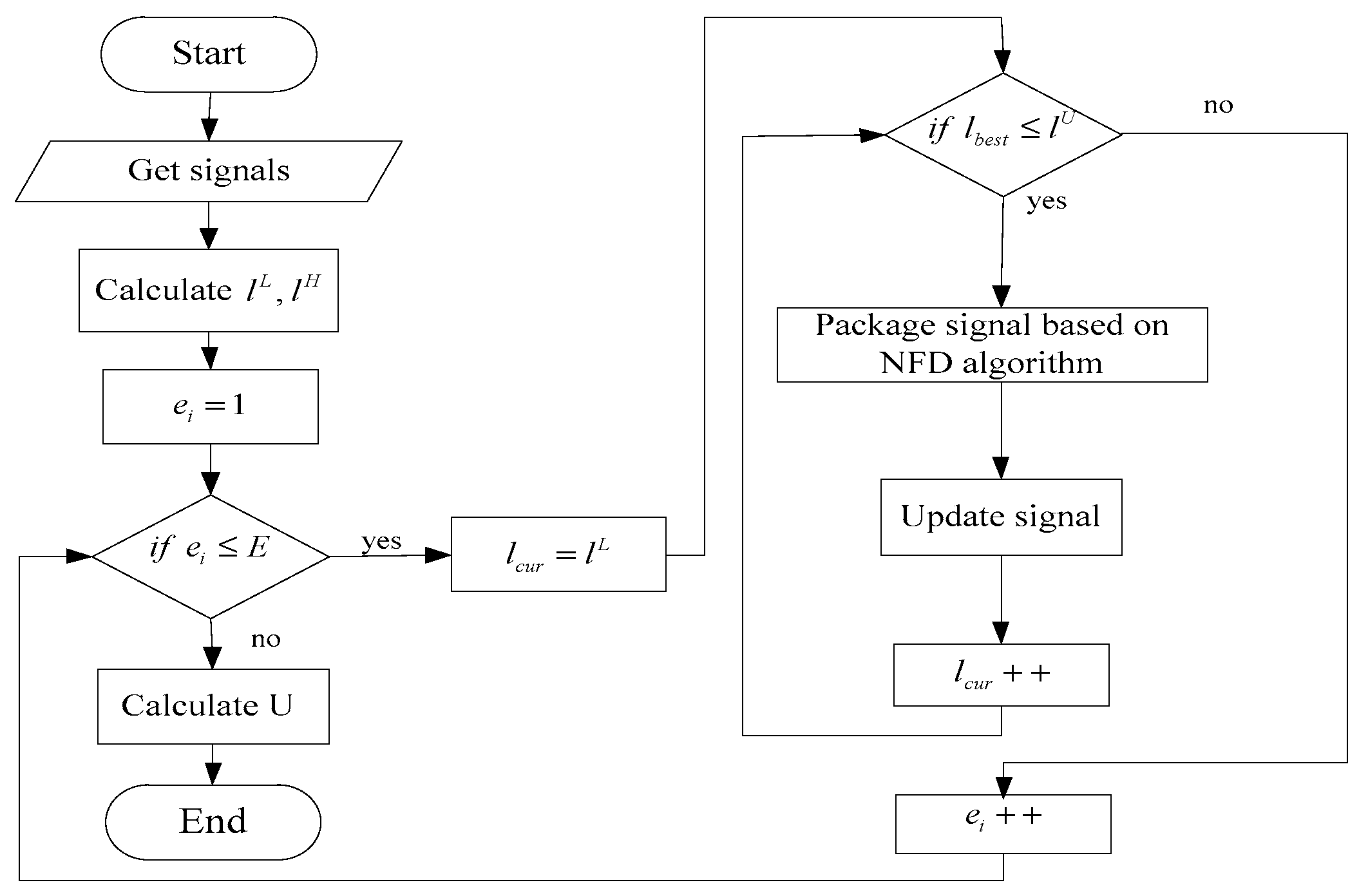
Figure 3 is a signal package flow chart, the main operation flow is as follows:
- (1).
Obtain the signal information corresponding to each node.
- (2).
The signal of each node is arranged in ascending order of the repetition rate, and the signal of the same repetition rate in each node is arranged in descending order of the size of the data bits.
- (3).
Calculate the exact value of the payload length of the frame, which means calculate the values of and , and initialize .
- (4).
According to the NFD algorithm, the nodes are packaged by sequentially. Finally, a message set is obtained.
- (5).
Calculate a super-periodic network utilization in the case of the payload length of the current frame, that expressed as , if , update the current message set.
- (6).
Set and repeat steps (4) and (5), loop until .
- (7).
Take the maximum value of when the corresponding message set and its corresponding frame payload length .
4. Frame ID Reusing
After signal packing, we can get the best length of payload and the best network utilization. Based on this, a schedule of frame ID (FID) reusing is constructed. The reuse of FID is important to scheduling strategy, making the schedule to occupy the least slots under the requirements of real-time system, so as to retain as much free slots. As well as, when new nodes and new frames are added for scaling, not only the flexibility of the static schedule be improved, but also the network resources are saved as much as possible. Scheduling for frames of FlexRay network is shown in
Figure 4.
As shown in
Figure 4, the repetition of message
is 2, the repetition
of message
is 4, the repetition of message is determined by sending periodic
and communication cycle
.
The period when message
is sent on the bus for the first time is called basic cycle, which can be represented in
Figure 4 by the y-offset of the y-axis. So, the base cycle of message
is 1, the base cycle of message
is 3, and the base cycle of message
is 0. The basic cycle constraints are as follow.
The relationship between basic cycle
and repetition rate
is shown in Equation (13),
is the period for sending the current message. Where,
.
The offset
is the location in the slot where message
was sent, which can be represented in
Figure 4 by the x-offset of the x-axis. Such as the offset of message
is 4, the range of the offset is as shown in Equation (14). Where
is the size of static slot,
is the size of message.
For a set of packaged messages , the messages are sorted according to the following rules to ensure that the messages are closely arranged in the schedule and do not intersect each other.
(1) The message having the smaller repetition rate will be sent more frequently. So, the message with a smaller repetition rate is arranged transmitting first. For the larger repetition rate of messages, it can be arranged flexibly because of they occupied fewer cycles. Thus, the remaining cycles are used to put them. Therefore, for message of each node, it should be arranged in the ascending order according to the repetition rate of packed messages.
(2) For messages with the same repetition, be sure to place the larger message at first, and fill the remaining payload in that slot with the smaller message. Therefore, messages in each node with the same repetition rate should be arranged in the decreasing order of its length.
(3) They should not intersect for all repeated message in the schedule arrangement. Even if messages
and
have the same slot, the schedule does not intersect because of their different cycles.
All messages are sorted in ascending order by repetition rate as shown in
Table 2, the repetition of
is same as
and
, sort in descending order of payload size. When the message frame is assigned to the schedule, it is allocated from the low period. The communication cycle of FlexRay is 0–63. Because the frame is sent repeatedly according to the period, the sampling cycle
is the super period of frames. In the case of message sent form nodes in
Table 2, only 0–7 cycle needs to be considered.
In order to obtain better configure of the schedule,
rows that have the same slot even though have different periods could be regarded as the same one column. Then, the reciprocal of the repetition is taken and added up. When the sum is 1, the message has been configured to fill this slot. For example, the message repetitions
are respectively 1, 2, 2, 2, 4, and 8 in
Table 2. They have the reciprocal of 1, 1/2, 1/2, 1/2, 1/4, 1/8, respectively. If the repetition of message is 1, it indicates that one slot is full filled. If the reciprocal of
and
is 1/2, they will occupy one slot. In the other case, the cumulative sum of messages
is 7/8. Though the sum of them is less than 1, the nodes of messages has been assigned slots, so the message
will occupy a whole slot. The scheduling strategy which was provided in this paper was used in
Table 2 to get the schedule shown in
Figure 5.
FID can be shared when frames are from the same node. For each node
, required number of
FID is:
The equation is extended to a system with
frames for
nodes, Then, required number of
FID is given by Equation (19).
5. Experimental Results
To evaluate our message scheduling method, we applied it to the communication system which has 4 nodes in BMW X7. The duration of communication cycle is the typical value of 5 ms in where the static segment occupies 3 ms and the dynamic segment occupies 2 ms. And other simulation parameters are shown in
Table 3. The table shows the configuration of FlexRay network parameters dedicated to construct the data frame. In this study, we designed experiments with two different sets of data (
Table 4 and
Table 5).
Table 4 shows the SAE benchmark data.
Table 5 shows the signal parameters of BMW’s 7 series where signal repetition rate is set to 1, 2, 4 and 8 respectively. Both of
Table 4 and
Table 5 shows in detail about the period of transmitted signals of each ECU, repetition, and data length. The experiment was as follows.
(1) Using the SAE benchmark data. Let signals of
Table 4 as experimental raw data. Repetition values are set to 1, 2, and 20. The sample signal’s length is equal to 8 bits and randomly expanded. The proposed algorithm and BCBFD algorithm which BC and BFD is an abbreviation of Bandwidth Consumption and Best Fit Decreasing respectively [
15], are used to the signal set packing, respectively. Compared the upper and lower limits of payload data payload length, as well as bus utilization and the number of slots.
Figure 6 shows that how the upper and lower bound of the frame’s payload of
,
change when the number of signals increases. As shown in
Figure 6, the lower bound of the frame payload length of the two algorithms is fixed and have equal values. It is determined by the maximum value of the length of all signals in the node. It results in the effective length of 8 bits in a single signal payload without considering a signal expanding. Even in the case of continually increased
, it can be seen that the NFD scheduling algorithm can effectively control the increase of the upper bound of the payload, and save operation time.
As shown in
Figure 7, the result of the curve of network utilization indicates that the average network utilization rate of scheduling algorithm proposed in this paper has a higher value than the average network utilization rate of BCBFD algorithm. Even though the network utilization of BCBFD algorithm increases with the number of signals, there is a gap that compared with the algorithm in this paper. This shows that the NFD scheduling algorithm has a stronger ability to save network resources.
The comparison of the slot number is shown in
Figure 8. The number of FIDs in BCBFD algorithm increases linearly with the number of messages, while the number of FIDs in NFD algorithm increases slowly. The conclusion is that the NFD scheduling algorithm is stronger than the BCBFD algorithm in resolving scheduling problems of static segment.
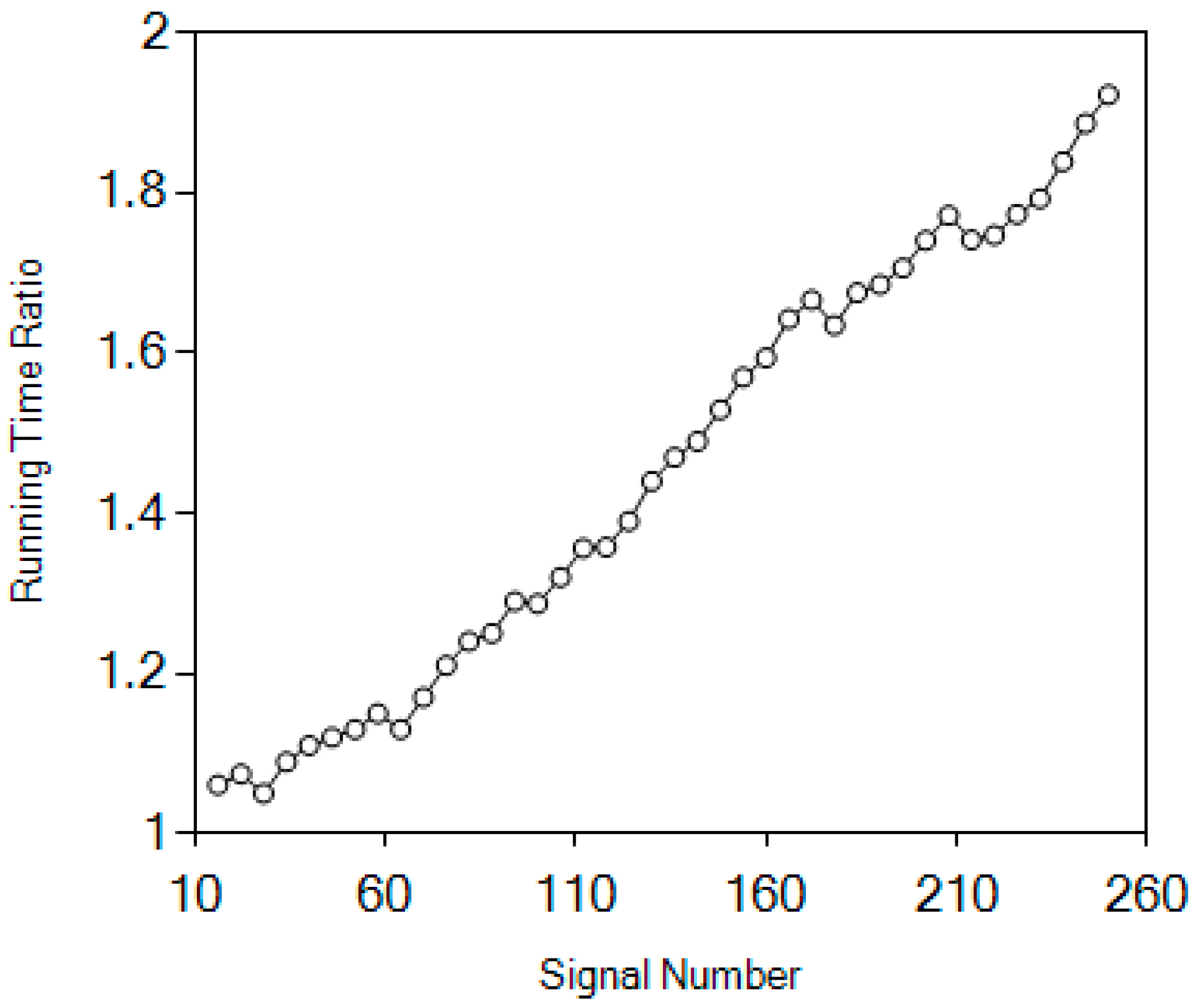
BCBFD algorithm and NFD scheduling algorithm execution time ratio is shown in
Figure 9. The bound of upper and lower of the length payload segment are precisely calculated, also effectively reduced. The number of iterations of the algorithm is reduced, and the execution efficiency of the algorithm is improved.
(2) Using the BMW’s 7 series data, to show the benefits of the NFD algorithm, we used the illustrative case, and compared with BCBFD algorithm [
15]. The experiment is based on the vehicle bus simulation tools Network Designer and CANoe. FlexRay where the network system is built on. The case uses the data of
Table 5. The signal data length is 2–20 bit, the payload length is taken as 20–56 bits, and the repetition rate of BMW 7 Series are 1, 2, 4, and 8.
Using the data in
Table 5, two algorithms were used to packing the signal sets into frames to obtain the respective package combinations. They are shown in
Table 6 and
Table 7. Without modification in the numbers of both ECU and transmitted signal, based on the NFD algorithm proposed in this paper and the BCBFD algorithm [
15], a reconstruction of transmitted signal is executed. Then, the database is built by Network Designer, and imported into the softwares CANoe and FlexRay. As shown in
Figure 10, four node ECUs are set up in the simulation network of CANoe. FelxRay that are used to transmitted frames. The proposed NFD algorithm and BCBFD algorithm were simulated and compared. Network performances of two different algorithms are compared and shown in
Table 8. Data in the table shows that the busload is reduced by 16.3%, the bandwidth utilization is increased by 32.8%, and the number of frame FIDs is reduced by 53.8%. The proposed algorithm can reduce the number of time slots and effectively reduce the network payload, and the network utilization has also been improved.


