Experimental Study on Flexural Behavior of TRM-Strengthened RC Beam: Various Types of Textile-Reinforced Mortar with Non-Impregnated Textile


Abstract
:
1. Introduction
2. Experimental Program
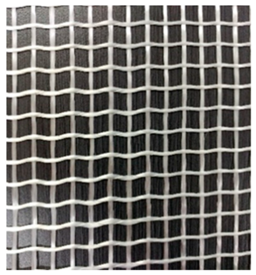
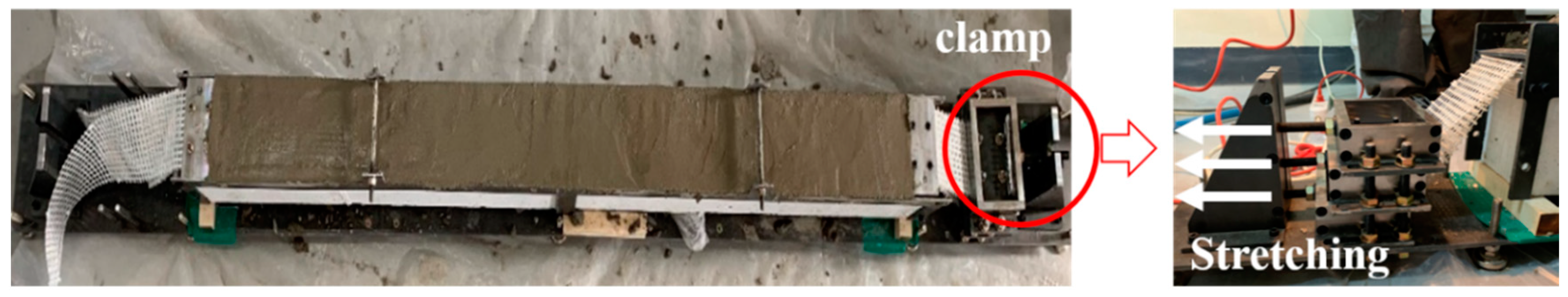
2.1. Textile
2.2. Matrix
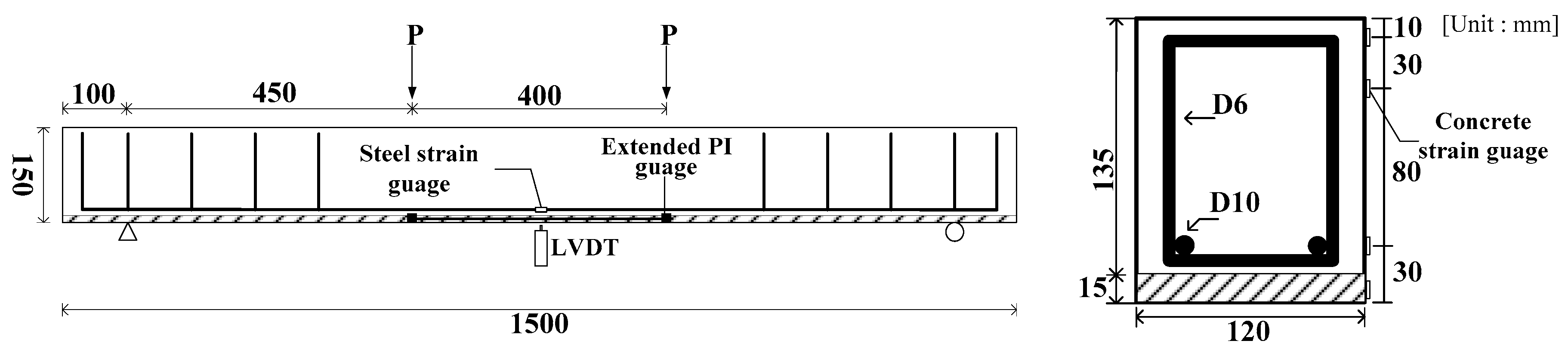
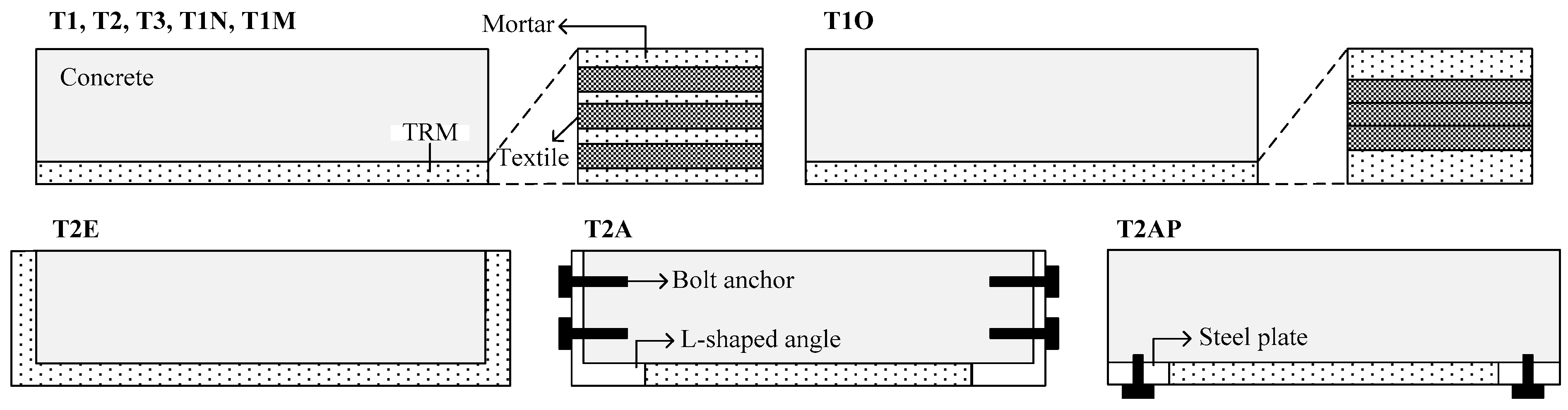
2.3. Specimen
2.4. Test Set-Up
3. Experimental Results and Discussion
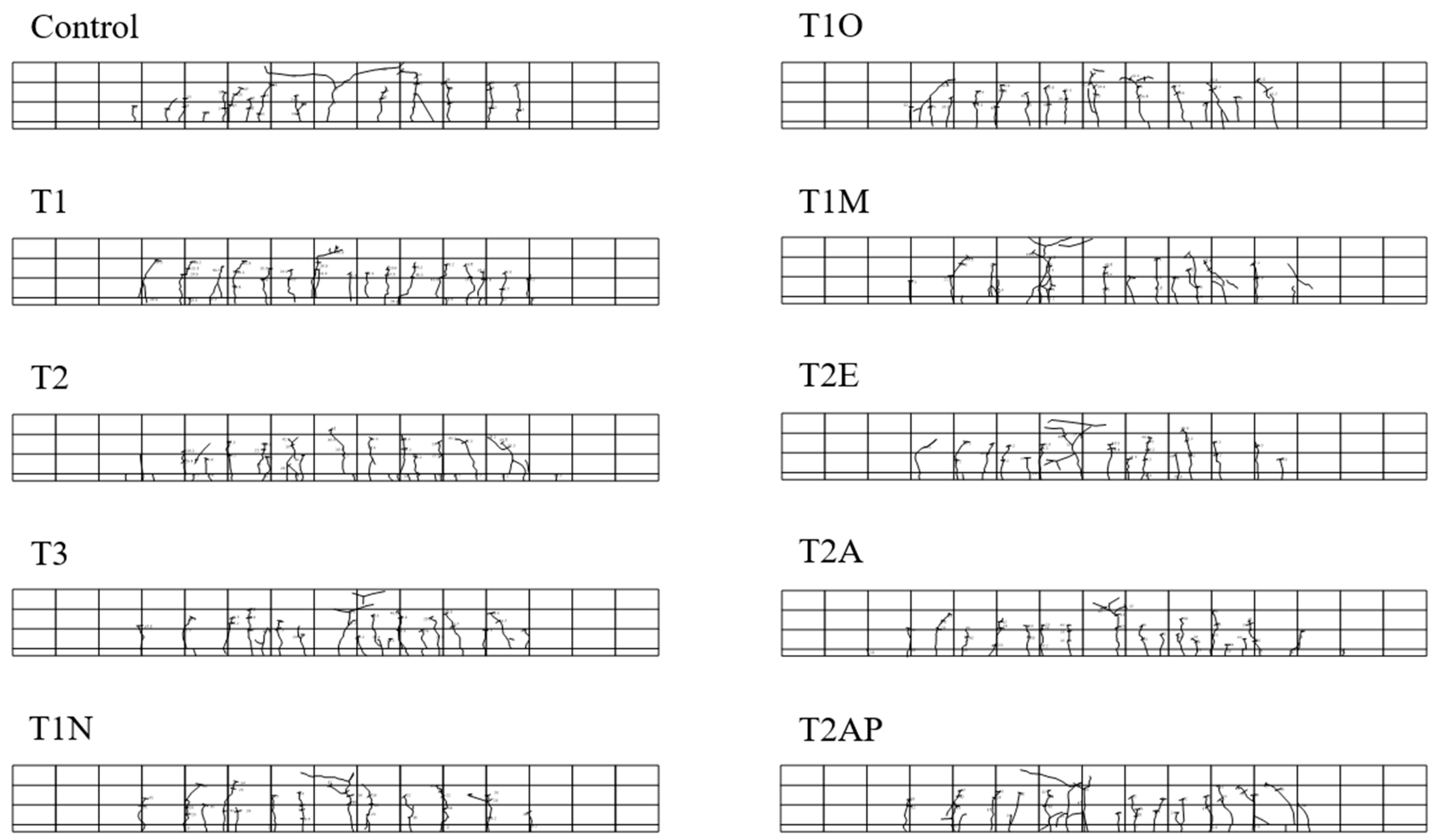
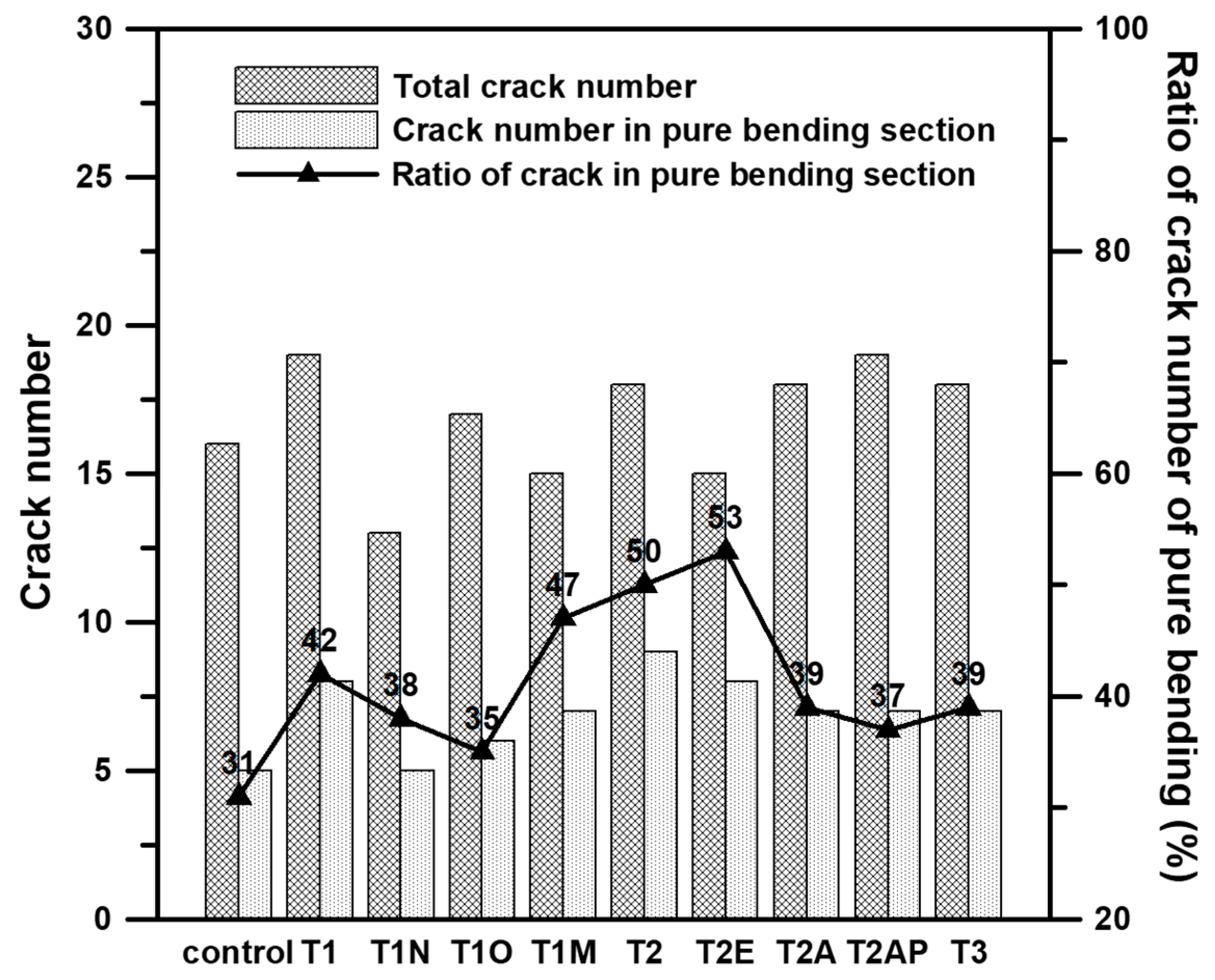
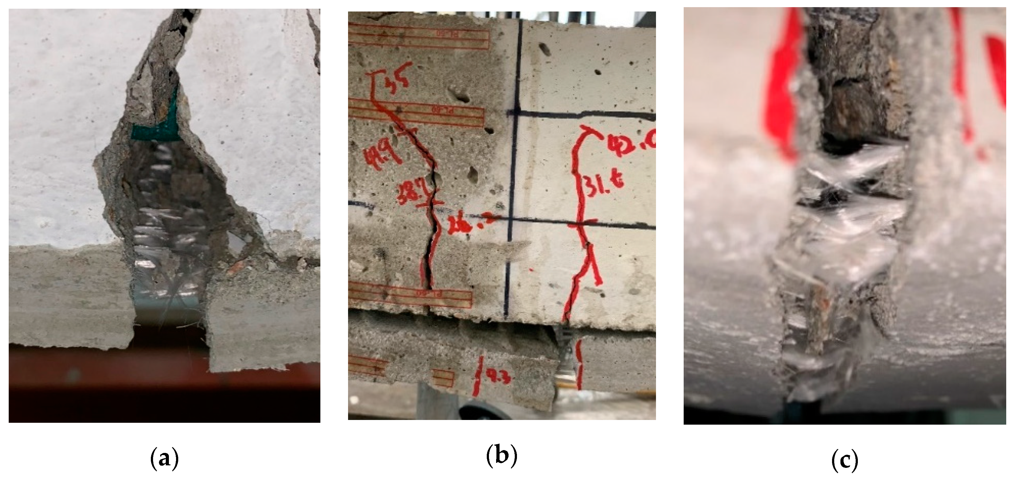
3.1. Crack and Failure
3.2. Load and Deflection Relationship
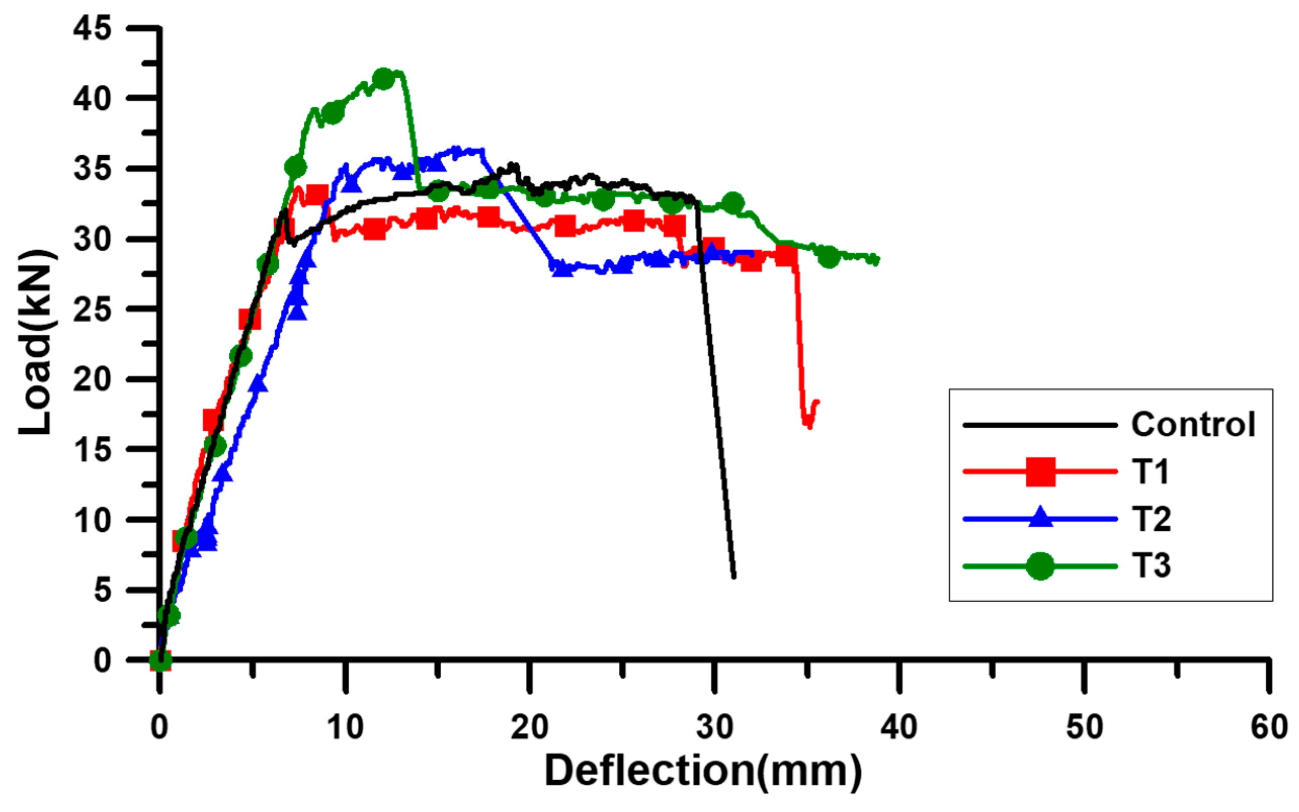
3.2.1. Textile Reinforcement Ratio
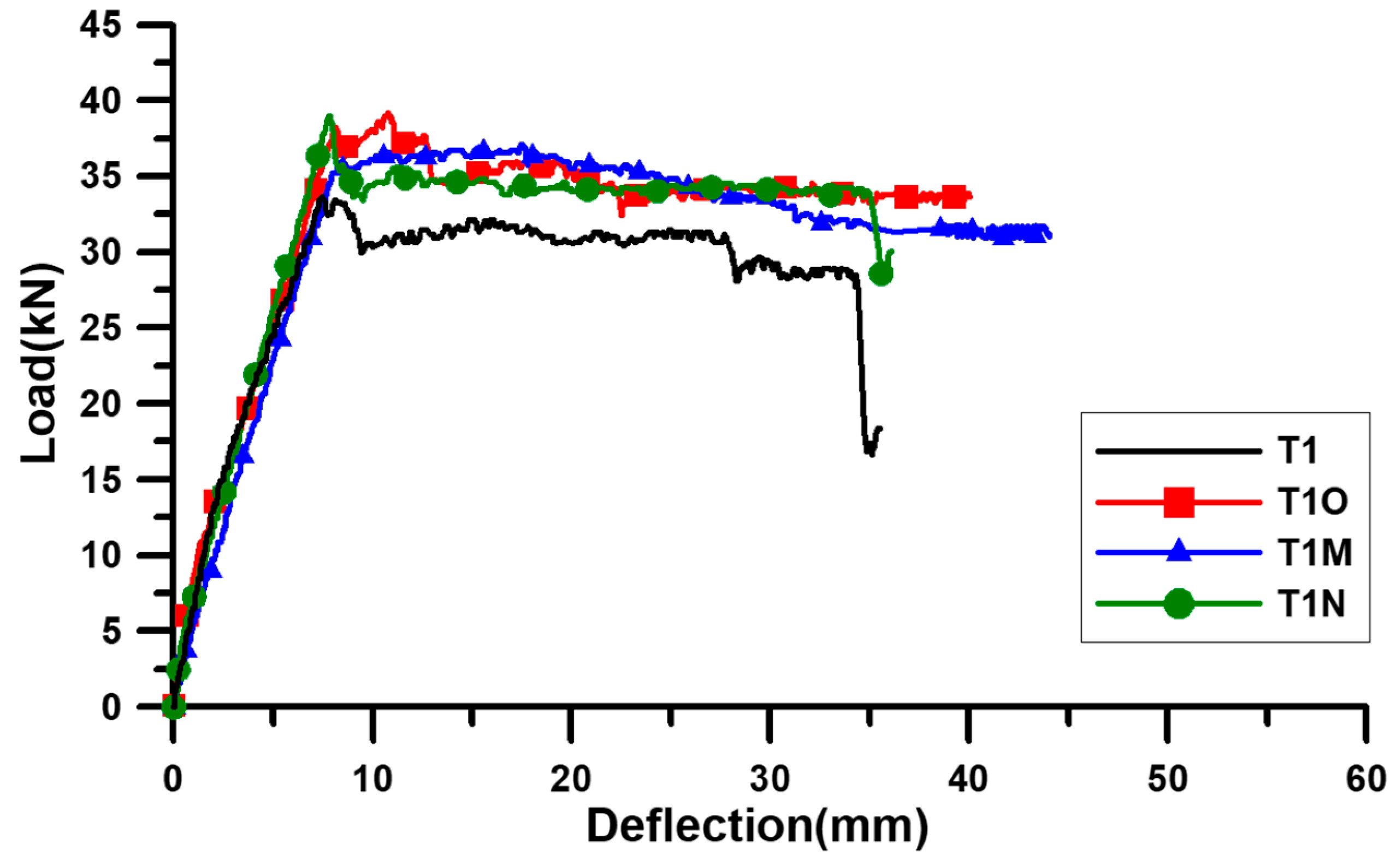
3.2.2. Textile Lamination and Geometry
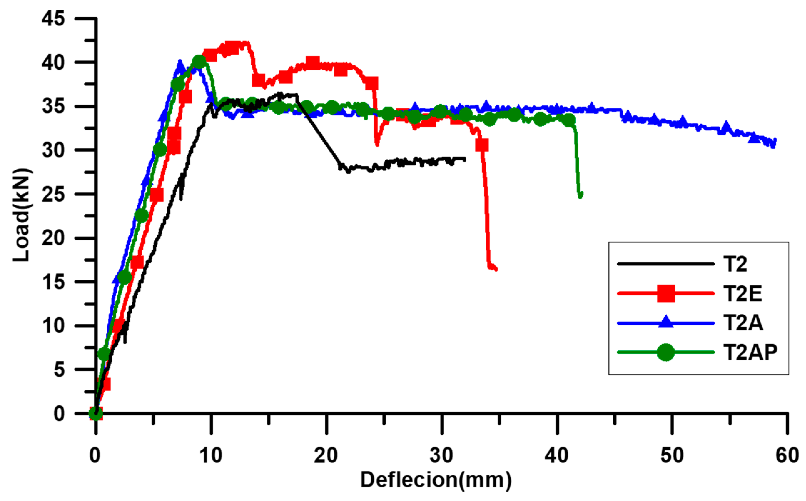
3.2.3. End Anchorage
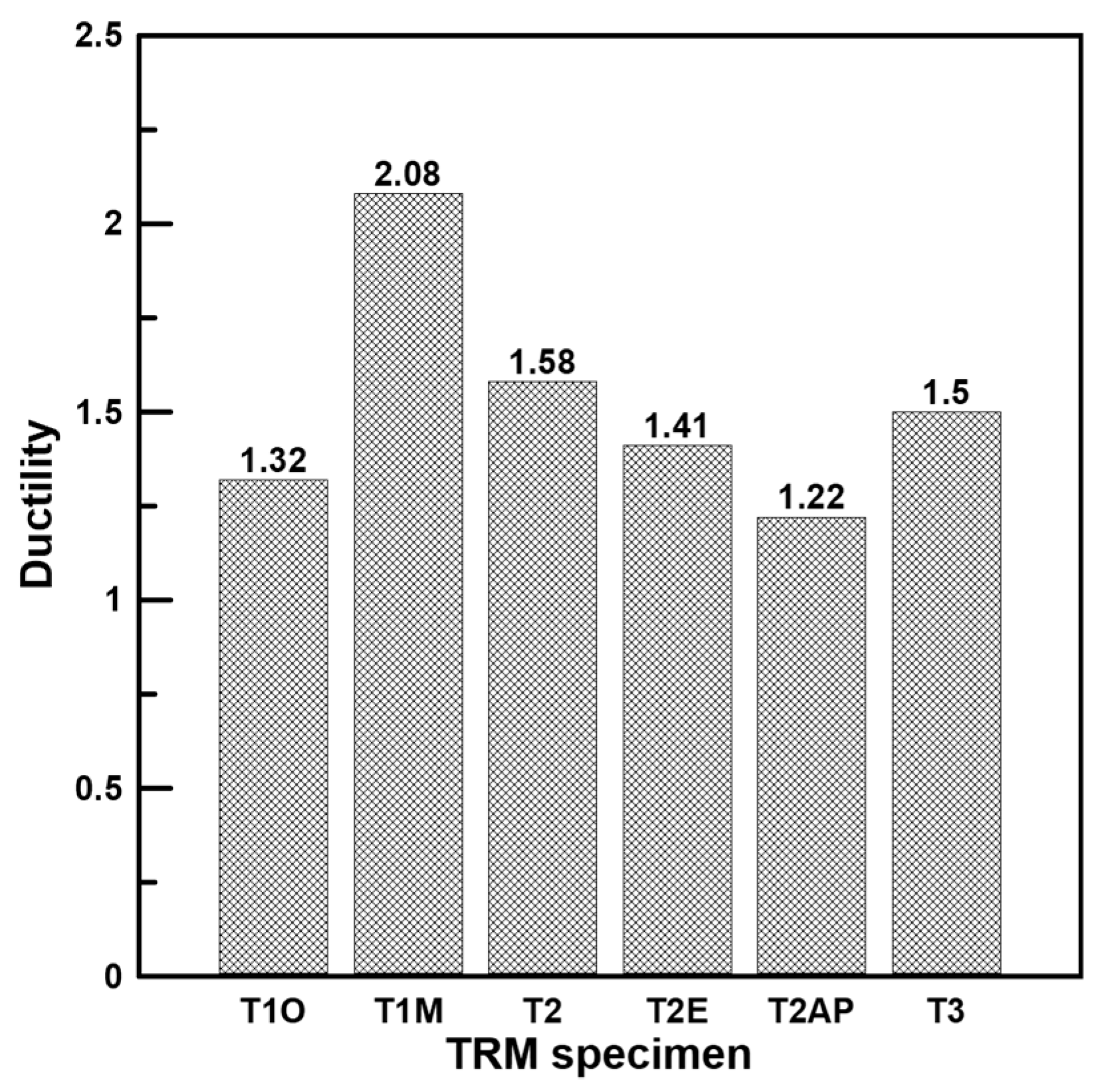
3.2.4. Ductility
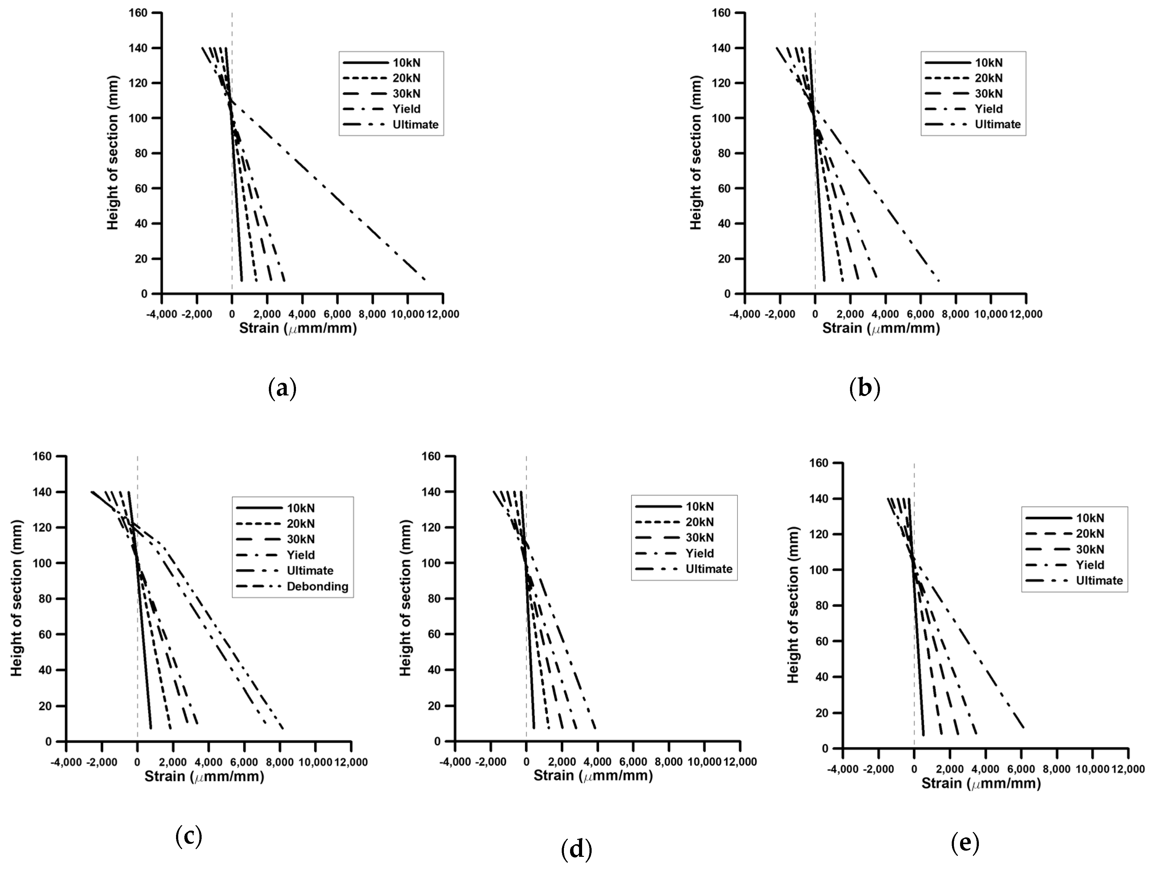
3.3. Strain
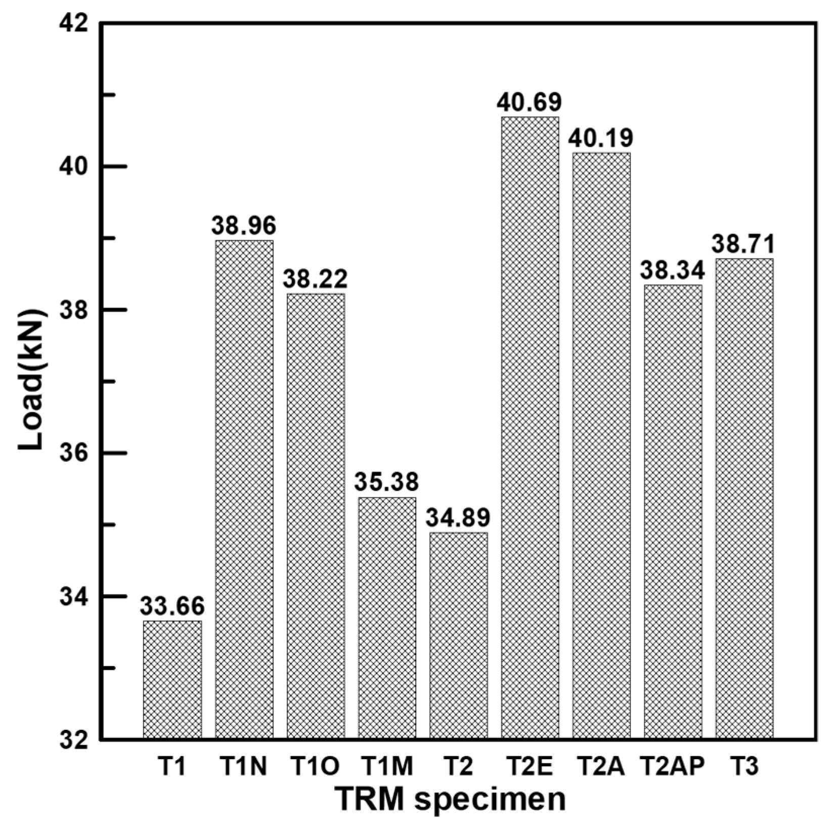
3.4. Comparison of Yield Loads of Studies Specimens
4. Conclusions
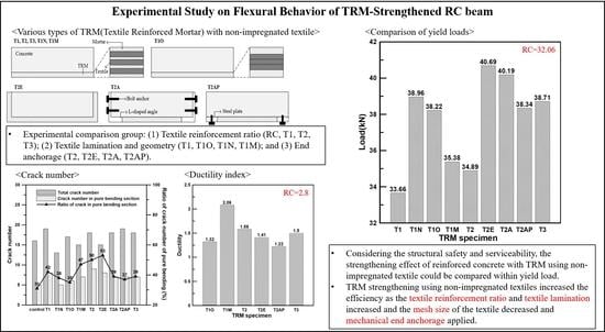
- There were multiple cracks in the pure bending of the TRM specimen compared with control specimen. However, in the case of using textile lamination, the ratio of bonding area with textile and mortar decreased compared to the total cross-sectional area of the textile, and in the case of applying mechanical end anchorage (T2AP, T2A), the initial crack strength increased. In both cases, the cracking ratio of the pure bending section was lowered. Nevertheless, TRM strengthening was beneficial for uniform distribution of cracks.
- Non-impregnated textile is easily damaged and slipped. Experimental results show that the case of lamination of textile can reduce the damage of the textile, but it does not prevent slippage. In the case of applying mechanical end anchorage, the slippage of the textile was expected to be completely prevented.
- Considering the low ductility of all TRM specimens compared with control specimens and that no ultimate load was observed in some specimens, the behavior of TRM specimens after yield load was considered to be unstable. Therefore, the TRM strengthening effect of non-impregnated textiles could be compared with the behavior before the yield load considering structural safety and serviceability.
- TRM strengthening using non-impregnated textiles increased the efficiency as the textile reinforcement ratio and textile lamination increased and the mesh size of the textile decreased and mechanical end anchorage applied. In this study, it was possible to have a load-bearing capacity similar to T3 with the largest textile reinforcement ratio by applying the above method.
Author Contributions
Funding
Acknowledgments
Conflicts of Interest
References
- American Society of Civil Engineers. 2017 Infrastructure Report Card, 1st ed.; American Society of Civil Engineers: Reston, VA, USA, 2017; pp. 7–8. [Google Scholar]
- Koutas, L.N.; Bournas, D.A. Flexural Strengthening of Two-Way RC Slabs with Textile-Reinforced Mortar: Experimental Investigation and Design Equations. J. Compos. Constr. 2017, 21, 1–11. [Google Scholar] [CrossRef]
- Arduini, M.; Nanni, A. Behavior of Precracked RC Beams Strengthened with Carbon FRP Sheets. J. Compos. Constr. 1997, 1, 63–70. [Google Scholar] [CrossRef]
- Hong, S.; Park, S.K. Effect of prestress levels on flexural and debonding behavior of reinforced concrete beams strengthened with prestressed carbon fiber reinforced polymer plates. J. Compos. Mater. 2013, 47, 2097–2111. [Google Scholar] [CrossRef]
- Hong, S.; Park, S.K. Prestressing effects on the performance of concrete beams with near-surface-mounted carbon-fiber-reinforced polymer bars. Mech. Compos. Mater. 2016, 52, 305–316. [Google Scholar] [CrossRef]
- Brameshuber, W. Textile Reinforced Concrete—State of the Art Report of RILEM TC 201-TRC, 1st ed.; RILEM: Aachen, Germany, 2006; pp. 1–271. [Google Scholar]
- Babaeidarabad, S.; Loreto, G.; Nanni, A. Flexural Strengthening of RC Beams with an Externally Bonded Fabric-Reinforced Cementitious Matrix. J. Compos. Constr. 2014, 18, 1–11. [Google Scholar] [CrossRef]
- Baiee, A.; Rafiq, I.; Lampropoulos, A. Innovative technique of textile reinforced mortar (TRM) for flexural strengthening of reinforced concrete (RC) beams. In Proceedings of the 2nd International Conference on Structural Safety Under Fire and Blast Loading, London, UK, 10–12 September 2017. [Google Scholar]
- Hartig, J.; Häußler-Combe, U.; Schicktanz, K. Influence of bond properties on the tensile behaviour of Textile Reinforced Concrete. Cem. Concr. Compos. 2008, 30, 898–906. [Google Scholar] [CrossRef]
- Colombo, I.G.; Magri, A.; Zani, G.; Colombo, M.; di Prisco, M. Textile Reinforced Concrete: Experimental investigation on design parameters. Mater. Struct. 2013, 46, 1933–1951. [Google Scholar] [CrossRef]
- Banholzer, B.; Brockmann, T.; Brameshuber, W. Material and bonding characteristics for dimensioning and modelling of textile reinforced concrete (TRC) elements. Mater. Struct. 2006, 39, 749–763. [Google Scholar] [CrossRef]
- Williams Portal, N.; Lundgren, K.; Walter, A.M.; Frederiksen, J.O.; Thrane, L.N. Numerical modelling of textile reinforced concrete. In Proceedings of the 8th International Conference on Fracture Mechanics of Concrete and Concrete Structures, FraMCoS 2013, Toledo, Spain, 11–14 March 2013; pp. 886–897. [Google Scholar]
- Zastrau, B.; Richter, M.; Lepenies, I. On the Analytical Solution of Pullout Phenomena in Textile Reinforced Concrete. J. Eng. Mater. Technol. 2003, 125, 38–43. [Google Scholar] [CrossRef]
- Iorfida, A.; Verre, S.; Candamano, S.; Ombres, L. Tensile and Direct Shear Responses of Baslat-Fibre Reinforced Mortar Based Materials. In Proceedings of the Strain-Hardening Cement-Based Composites (SHCC4), Deresden, Germany, 18–20 September 2017; RILEM: Aachen, Germany, 2018; pp. 544–552. [Google Scholar]
- Papanicolaou, C.G.; Papantoniou, I.C. Mechanical Behavior of Textile Reinforced Concrete (TRC) / Concrete Composite Elements. J. Adv. Concr. Technol. 2010, 8, 35–47. [Google Scholar] [CrossRef] [Green Version]
- Yin, S.P.; Xu, S.L. An Experimental Study on Improved Mechanical Behavior of Textile-Reinforced Concrete. Adv. Mater. Res. 2011, 168–170, 1850–1853. [Google Scholar] [CrossRef]
- Yin, S.; Xu, S.; Lv, H. Flexural Behavior of Reinforced Concrete Beams with TRC Tension Zone Cover. J. Mater. Civ. Eng. 2014, 26, 320–330. [Google Scholar] [CrossRef]
- Yin, S.P.; Xu, S.L.; Wang, F. Investigation on the flexural behavior of concrete members reinforced with epoxy resin-impregnated textiles. Mater. Struct. 2015, 48, 153–166. [Google Scholar] [CrossRef]
- Kamani, R.; Kamali Dolatabadi, M.; Jeddi, A.A.A. Flexural design of textile-reinforced concrete (TRC) using warp-knitted fabric with improving fiber performance index (FPI). J. Text. Inst. 2017, 109, 492–500. [Google Scholar] [CrossRef]
- Liu, L.; Du, Y.; Zhou, F.; Pan, W.; Zhang, X.; Zhu, D. Flexural Behaviour of Carbon Textile-Reinforced Concrete with Prestress and Steel Fibres. Polymers 2018, 10, 98. [Google Scholar] [Green Version]
- Raoof, S.M.; Koutas, L.N.; Bournas, D.A. Textile-reinforced mortar (TRM) versus fibre-reinforced polymers (FRP) in flexural strengthening of RC beams. Constr. Build. Mater. 2017, 151, 279–291. [Google Scholar] [CrossRef]
- Jesse, F.; Weiland, S.; Curbach, M. Flexural strengthening of RC structures with textile-reinforced concrete. ACI Spec. Publ. 2008, 250, 49–58. [Google Scholar]
- Gutierrez, E.; Bono, F. Review of Industrial Manufacturing Capacity for Fibre-Reinforced Polymers as Prospective Structural Components in Shipping Containers; Publications Office of the European Union: Luxembourg, 2013; pp. 5–12. [Google Scholar]
- Peled, A. Pre-tensioning of fabrics in cement-based composites. Cem. Concr. Res. 2007, 37, 805–813. [Google Scholar] [CrossRef]
- Koutas, L.N.; Tetta, Z.; Bournas, D.A.; Triantafillou, T.C. Strengthening of Concrete Structures with Textile Reinforced Mortars: State-of-the-Art Review. J. Compos. Constr. 2019, 23, 1–20. [Google Scholar] [CrossRef]
- Reinhardt, H.W.; Krüger, M.; Große, C.U. Concrete Prestressed with Textile Fabric. J. Adv. Concr. Technol. 2003, 1, 231–239. [Google Scholar] [CrossRef] [Green Version]
- Du, Y.; Zhang, M.; Zhou, F.; Zhu, D. Experimental study on basalt textile reinforced concrete under uniaxial tensile loading Experimental study on basalt textile reinforced concrete under uniaxial tensile loading. Constr. Build. Mater. 2017, 138, 88–100. [Google Scholar] [CrossRef]
- Hegger, J.; Will, N.; Bruckermann, O.; Voss, S. Load-bearing behaviour and simulation of textile reinforced concrete. Mater. Struct. 2006, 39, 765–77628. [Google Scholar] [CrossRef]


| Properties and Geometric Parameters 1 | AR Glass |
|---|---|
| Number of filaments per roving | 1600 |
| Tensile strength of warp (N/50 mm) | 2142 |
| Tensile strength of weft (N/50 mm) | 1833 |
| Rupture elongation ratio of warp (%) | 2.85 |
| Rupture elongation ratio of weft (%) | 2.36 |
| Tex of yarn (g/km) | 640 |
| Diameter or filament (μm) | 14 |
| W/B (%) | Unit Weight | ||||||
|---|---|---|---|---|---|---|---|
| Cement | Water | Fine Aggregate | Coarse Aggregate | Fly Ash | Blast Furnace Slag | Water Reducer | |
| 35.8 | 319 | 163 | 780 | 898 | 68 | 68 | 4.1 |
| W/M 1 (%) | Content Per 1 Bag of 25 kg (%) | |||||
|---|---|---|---|---|---|---|
| Cement | Fine Aggregate | PVA Fiber 2 | Acrylate Copolymer | CSA 3 | Water Reducer | |
| 19 | <50 | 35~40 | >1 | 3> | >5 | <1 |
| Strength Type | Experimental Value (MPa) | Standard of KS (MPa) |
|---|---|---|
| Flexural | 8 | |
| Compressive | 45 | |
| Bond 1 | 1.5 |
| Name | Strengthening Configuration | Textile | End Anchorage | |
|---|---|---|---|---|
| Layer | Lamination 2 | |||
| Control | Reinforced concrete | - | - | - |
| T1 1 | Textile reinforcement ratio was 0.049% | 3 | - | |
| T1N | Textile applied manually (non-stretching) | 3 | - | |
| T1O | Three textiles lamination in one layer | 1 | 3 | |
| T1M 2 | Textile mesh size changed from 8 mm to 24 mm | 3 | (1/3) × 3 | |
| T2 1 | Textile reinforcement ratio was 0.098% | 3 | 2 | |
| T2E 3 | Fixed to both ends of the beam by TRM | 3 | 2 | ○ |
| T2A 3 | L-shaped angle + bolt anchor | 3 | 2 | ○ |
| T2AP 3 | Steel plate + bolt anchor | 3 | 2 | ○ |
| T3 1 | Textile reinforcement ratio was 0.15% | 3 | 3 | |
| Name | Experiment Results | Failure Mode | ||||
|---|---|---|---|---|---|---|
(kN) | (mm) | (kN) | (mm) | μ | ||
| RC | 32.06 | 6.75 | 35.39 | 18.92 | 2.8 | Concrete crushing |
| T1 | 33.66 | 7.48 | - | - | - | Textile rupture |
| T1N | 38.96 | 7.85 | - | - | - | Textile rupture |
| T1O | 38.22 | 8.18 | 39.21 | 10.79 | 1.32 | Debonding and textile rupture |
| T1M | 35.38 | 8.42 | 37.11 | 17.48 | 2.08 | Textile slippage |
| T2 | 34.89 | 10.02 | 36.49 | 15.86 | 1.58 | Debonding and textile rupture |
| T2E | 40.69 | 8.85 | 42.29 | 12.45 | 1.41 | Textile rupture |
| T2A | 40.19 | 7.31 | - | - | - | Textile rupture |
| T2AP | 38.34 | 7.41 | 40.19 | 9.03 | 1.22 | Textile rupture |
| T3 | 38.71 | 8.53 | 41.92 | 12.79 | 1.50 | Textile rupture |
© 2019 by the authors. Licensee MDPI, Basel, Switzerland. This article is an open access article distributed under the terms and conditions of the Creative Commons Attribution (CC BY) license (http://creativecommons.org/licenses/by/4.0/).
Share and Cite
Park, J.; Hong, S.; Park, S.-K. Experimental Study on Flexural Behavior of TRM-Strengthened RC Beam: Various Types of Textile-Reinforced Mortar with Non-Impregnated Textile. Appl. Sci. 2019, 9, 1981. https://0-doi-org.brum.beds.ac.uk/10.3390/app9101981
Park J, Hong S, Park S-K. Experimental Study on Flexural Behavior of TRM-Strengthened RC Beam: Various Types of Textile-Reinforced Mortar with Non-Impregnated Textile. Applied Sciences. 2019; 9(10):1981. https://0-doi-org.brum.beds.ac.uk/10.3390/app9101981
Chicago/Turabian StylePark, Jongho, Sungnam Hong, and Sun-Kyu Park. 2019. "Experimental Study on Flexural Behavior of TRM-Strengthened RC Beam: Various Types of Textile-Reinforced Mortar with Non-Impregnated Textile" Applied Sciences 9, no. 10: 1981. https://0-doi-org.brum.beds.ac.uk/10.3390/app9101981