1. Introduction
A dermatoscope is the standard instrument for a first examination of skin conditions. The whole field of dermatoscopy started with the use of epiluminescence microscopes for this purpose [
1,
2,
3]. State-of-the-art dermatoscopy devices today are mostly contact based and often include a camera to capture digital images for documentation. Compared to a non-contact setup, a contact-based dermatoscope exhibits several disadvantages. State of the art contact-based dermatoscopes have built-in cameras to make the pictures digitally available. The skin contact may cause distortion of the skin geometry, which makes it more difficult to compare pictures made at different examinations. Also, the contact could suppress the perfusion hampering detection of small vessel structures. When thinking of infected lesions, the contact can also be painful and represents a larger invasion to the privacy of patients. A non-contact device circumvents all these problems. In addition, one can realise a larger field of view and the concept is much more compatible with automation approaches. Challenges of a non-contact design are the implementation of a variable focus and the realization of a lighting situation, which is independent from the surrounding light.
In order to exploit the advantages of the non-contact design with regard to automation, some challenges need to be addressed. For example, to obtain sharp images, focus control is required. The preferred solution for easy handling or automation is an autofocus system. For documentation and post-processing, the images should also be digitally available. Whereas digital image acquisition is already state-of-the-art in contact-based devices [
4,
5], the documentation is required to compare pictures from different examinations in order to identify changes in size or color of relevant skin areas. The size of a nevus is, for example, one criterion of the ABCDE (
Asymmetry,
Border,
Color,
Diameter,
Evolving) rule of dermatoscopy to visually identify malignant melanoma [
6,
7]. Therefore, it is necessary to record comparable images in non-contact mode without distortion of the skin geometry, as skin contact with standard devices can significantly distort the geometry and suppress blood perfusion correct assessment of skin lesions if often difficult [
8]. As the hemoglobin of the blood, besides melanin, is one of the two dominant dye molecules in the skin, the suppression results in a color change of the skin area under study. The comparison of skin colors is not only important for skin cancer screening but also interesting, for example, for inflammatory skin diseases (e.g., erythema in the Psoriasis Area and Severity Index (PASI)). To enable to calibrate the camera sensor in a way that colors can be identified and compared between images made at different examinations and possibly under different ambient light situations, a bright light source is needed.
A dermatoscope provides 2D information about light intensity and color of the imaged location, i.e., skin area. As this is the same information generated by the human eye, the resulting data is comparably intuitive for the dermatologists. In addition, to obtain information from deeper layers of the skin, cross polarization can be used (see
Section 2.3) [
9]. Other techniques like optical coherence tomography (OCT) [
10,
11,
12] or high frequency ultrasound [
11,
13] normally generating a 2D depth images are based on the optical thickness (for OCT) or the time of the propagation of the acoustic waves in the medium (for ultrasound), respectively. For these modalities, by scanning a 2D area, 3D information is generated. The resulting data, however, do not provide information about the color of the tissue and special training is required for their correct interpretation. Also, compared to dermatoscopes, OCT and high frequency ultrasound devices are much more expensive. Thus, there is a need for simple, easy-to-operate and yet accurate dermatoscope systems capable of providing the functionality required for proper skin examination without distortion of the geometry, i.e., in non-contact mode.
In this work, we present a novel non-contact dermatoscope featuring properties advantageous for more reliable and comparable skin examinations in the future. The light source of the developed prototype is an ultra-bright white light-emitting diode (LED), which allows for full control of the lighting situation to be independent from the surrounding light. Also, by realizing a calibrated display, it is possible to display the natural colors of the skin area. Furthermore, the non-contact approach enables a much larger field of view. While pigmented nevi that are examined in melanoma screening are often 0.5–2-cm wide, inflammatory lesions are generally several centimeters wide. Thus, their examination requires a much larger field of view of the imaging system compared to a device designed for skin cancer screening only. The prototype described here has a field of view of about 17 × 13 mm2 and can, in the future, be combined with a second camera to record images of even larger skin areas.
1.1. State-of-the-Art Commercially Available Non-Contact Systems
A few non-contact devices for skin examination have already been reported. They can be categorized in (i) non-contact dermatoscopes, which have a high magnification (see for example [
4,
5]), and (ii) non-contact skin screening devices for overview images of the skin (see for example [
14]).
So far, different designs for non-contact dermatoscopes are utilized. One type is realized as a handheld magnifying glass while another is configured as an adaptor for mobile phones. The latter use the camera of the mobile phone to take the images. Other devices rely on built-in camera and illumination sources. However, all these systems are applied at short working distances of a few centimeters. An important aspect in this context is (auto)focusing, which has to be considered for all non-contact devices. For example, non-contact devices with more than 2 cm working distance use spacers to avoid the need of autofocusing. Furthermore, the illumination conditions are more difficult to control for non-contact devices as environmental influences are more relevant. Thus, sufficiently bright light sources are needed to ensure reproducible illumination conditions [
4,
5].
Further concepts rely on imaging systems at large working distances, which provide only overview images of the skin with lower resolution compared to dermatoscopes. They usually make use of standard cameras with passive autofocusing techniques that employ phase or contrast detection. The cameras are mounted on a movable holder so that images of the whole body can be taken. As room light is used for illumination it is difficult to compare images taken under varying lighting conditions [
14].
1.2. Prototype of the New Non-Contact Device
The main advantages of the non-contact prototype system presented in this work are the large working distance while providing the high-resolution level of contact-type dermatoscopes. At present, the prototype is optimized for a working distance of 45 cm ± 3 cm. This is realized with a liquid lens-based autofocus, which has not yet been used for this purpose so far. In principle, other working distances are also possible requiring only marginal changes to the current design as further discussed in
Section 2.
As an illumination source, an ultra-bright LED light source with full polarization control is used. This choice makes the device independent from the surrounding light situation and allows reproducible color measurements. Also, the color of different skin sites and lesions can more easily be compared between different images. Such analysis is, for example, important for skin cancer screening as multiple colors and color changes can be indicative of melanoma [
6]. Due to the design on a swivel arm the ultra-bright light source can easily be powered. By controlling the polarization state of the measured light, the physician can increase or decrease the contrast of the surface morphology as desired. The presented autofocus function is fast compared to iterative autofocus solutions, which are based on contrast analysis of the captured image. Also, the built-in infrared distance sensor can provide information about the scale in the taken image. The new non-contact system allows for automated imaging functionality so the physician is able to map the skin without manual activity.
First preclinical studies with an earlier version of our non-contact dermatoscope indicated the potential benefit of the system [
8]. For example, in the investigation of inflammatory skin diseases such as lichen ruber planus and psoriasis subtle details of the lesions could be visualized and natural color appearance ensured. With the early stage of the system structural changes such as hypergranulosis [
15] were visible for lichen ruber planus. In psoriasis, variations of the capillary vessels could be seen. For this inflammatory skin disease, characteristic blood vessels are opening in the upper skin. These vessels are normally seen in the histopathology of the diseased skin. With the non-contact prototype, it was possible to observe these vessels as round structures in the image. This success could lead to a reduction of necessary biopsies for differential diagnosis. In the future, the newly designed setup described here could be part of an automated skin scanner where the patient is screened at a first examination stage without the need for a dermatologist to be present. However, the system described in [
8] did not feature an autofocus function. Also it was mounted on a stable substrate board so that the patients had to move in front of it. Thus, not all regions of interest on a patient’s body could be reached and handling by the dermatologist was still limited. Also, image acquisition took longer so that fewer patients could be examined. Using the new system presented in this work, even lesions on hard-to-reach areas of the body could be examined with high resolution.
2. Materials and Methods
Figure 1 shows the non-contact dermatoscope developed in this work. The setup consists of a camera with liquid lens-based autofocus and an illumination unit. An infrared laser distance sensor is attached besides the illumination unit. The camera is connected to a computer for control of the setup and image post processing. A movable polarizer is mounted in front of the liquid lens. The illumination unit consists of an ultra-bright white LED-chip and a reflector that redirects the light emitted by the LED and illuminates the region of interest homogeneously. A fixed polarizer is mounted in front of the reflector. In the subsections below, the different parts of the prototype are described in detail.
The setup is mounted on an aluminum plate that is connected to the swivel arm mounted on a table that makes it possible to adjust its position in the room and with respect to the patients. The camera, the polarizers and the liquid lens are connected to a computer, which controls the system and performs digital image processing. Component costs for the presented non-contact dermatoscope are approximately 4000 €.
2.1. Camera with Liquid Lens-Based Autofocus
We integrated a liquid lens-based autofocus as a novel solution for the variable focus problem in a freely movable non-contact dermatoscope. A liquid lens has the advantage of fast tunability of the focal length. The liquid lens consists of a reservoir filled with an opto-fluid delimited by a transparent membrane consisting of silicon or thin glass. The reservoir is enclosed by a Piezo ring, which can increase the pressure in the reservoir if an electrical voltage is applied to it. The pressure leads to different curvatures of the membrane, which results in different focal lengths of the lens. The schematic setup of the camera is shown in
Figure 1. The radius of curvature of the lens is controlled by the distance sensor. The system is adjusted so the skin area of interest is always in the focus. This is ensured by actively measuring the distance between the target and the camera to follow the target even if the latter is not illuminated or does not show visible sharp edges.
The camera (FL3-GE-28S4C-C, FLIR Integrated Imaging Solutions, Inc., Richmond, BC, Canada) has a resolution of 1928 × 1448 and a maximum image rate of 15 frames per second (FPS). It is equipped with an ICX687 CCD color sensor by Sony (Minato, Tokio, Japan) which has a sensor size of 1/1.8′′ and a pixel size of 3.69 µm. To record a dermatoscopic view of the skin, a zoom lens (NMV-75M1, Navitar, Rochester, NY, USA) with a focal length of 75 mm is mounted in front of the camera. In addition, the liquid lens (EL-16-40-TC, Optotune AG, Dietikon, Switzerland) is mounted in front of the zoom objective with a self-made adapter. It is an electrically tunable large aperture lens (with a clear aperture of 16 mm). The lens is controlled by the Optotune Lens Driver 4i via the “Lens Driver Controller” software. In order to realize an autofocus system, the tunable lens was combined with a distance sensor (DT35-B15851, Sick AG, Waldkirch, Germany). The lens driver can process an analog input signal from the distance sensor to set the correct focus length for a sharp image of the target. The distance sensor is based on an infrared laser distance sensor operating at 827 nm. It has an accuracy of 0.5 mm in the relevant range below 1 m, depending on the reflectivity of the target and the measurement speed, which is set. This setup realizes a fast autofocus as it does not contain moving parts. It is calibrated with the lens driver controller software. Here, a look-up table can be configured which relates every measured distance to a specific voltage for the liquid lens. The lens needs around 5 ms to respond and around 25 ms to settle to the new focal length. The exact settle time depends on the voltage difference applied to the lens. The distance sensor has a time delay of 6.5 ms between the measured event and the output signal in the “fast” mode. This results in a total delay from the event to the settling of the lens of approximately 31.5 ms and allows to adjust the focus approximately 30 times a second, which is twice the frame rate of the camera. As patients usually only move slowly and slightly during dermoscopy, the autofocus is able to focus on the target all the time.
As the camera and the distance sensor are not coaxially aligned, the functional distance of the setup is limited. The available focus distance is 45 ± 3 cm. If the distance sensor was arranged coaxially to the camera, for example, by aid of a dichroic mirror, it would be possible to focus over a much larger distance. A wider focal range could be realized in combination with an illumination unit that is able to homogeneously illuminate a larger area than the actual version with the same light intensity Though the used liquid lens is one of the biggest commercially available lenses by now, its aperture is much smaller than the aperture of the camera lens. This makes it necessary to choose the aperture of the camera to be smaller to avoid strong aberrations from the edge of the liquid lens. A small aperture also leads to a relatively low light exposure of the camera sensor, which needs to be compensated by larger exposure times. In dermatoscopy, exposure times are limited by the natural movement of the patient can be avoided, such as blurring or other movement artifacts. Due to the ultra-bright LED illumination, acceptable exposure times of 75 ms can be achieved.
2.2. Ultra-Bright LED White Light Source
For illumination, a phosphor based ultra-bright LED white light source (CBT-90 White LED, Luminus Inc., Sunnyvale, CA, USA) is employed. The source is phosphor based and converts blue light from an LED-chip into the yellow spectral range. The emitted light mixture exhibits a white spectrum, which is generally more continuous compared to a mixture of red, green, and blue (RGB) LED chips.
The source has a color rendering index (CRI) of 76 (for comparison: lighting in surgical rooms requires a CRI > 85 [
16]). In general, the closer the CRI of a light source is to the value of 100 the better the source can render the colors of real-world objects, i.e., skin lesion in our case. This then corresponds to the color perception during daylight.
The LED is mounted on a self-made reflector that was simulated and designed with OpticStudio (Zemax LLT, Kirkland, WA, USA) aiming at homogeneous illumination of a target at the highest possible intensity in the distance of interest (ca. 45 cm from the liquid lens). The bright illumination has the advantage, that the illumination of the target is well-defined and less influenced by the surrounding light. This is important for the color adjustment of the camera, which is of interest as the color of a lesion is a relevant parameter in dermatoscopy. For example, it is also taken into account in the ABCDE rule of dermatoscopy [
6,
7]. Also, it is of interest to evaluate the temporal evolution of a lesion. Furthermore, in the field of inflammatory skin diseases, different color variations need to be identified, e.g., shades of red. Another useful application area could be the color identification of hematoma allowing to predict the age of injuries of patients [
17,
18]. For detection of changes of the colors of lesions, the comparability of images taken at different examination sessions and different times must be ensured. Also, different disease stages could be assigned by evaluating the color (e.g., redness in the PASI as well as the Eczema Area and Severity Index (EASI), respectively). To fulfill these requirements, in particular, to allow for a more natural color representation comparable to the perception of a physician, color calibration is important. This ultimately also increases the acceptance of the system by the dermatologists.
2.3. Full Polarization Control
The concept of using polarized light for skin examination is well known in the literature [
19,
20,
21]. There are two polarizers in the setup presented in this work: one in front of the illumination unit and one in front of the liquid lens.
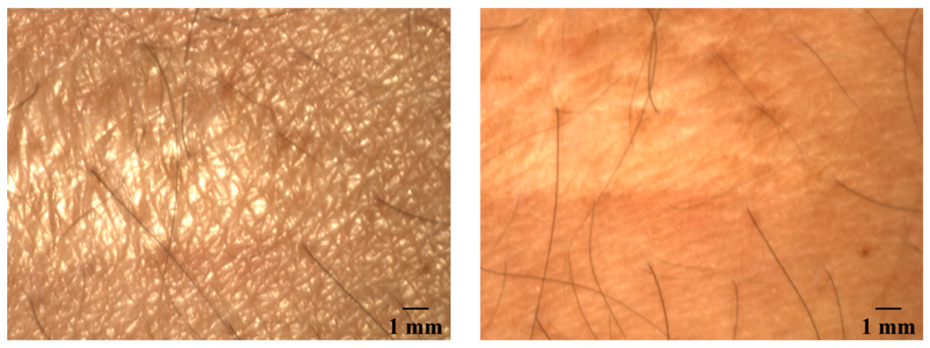
The polarizer in front of the camera is mounted on a rotation stage such that the operator can switch between cross polarization and parallel polarization by means of custom software. In cross-polarization mode, the orientation of the two polarizers is 90 degrees. Because the directly reflected light does not change its polarization for the most part, this light will be filtered out. Only light that is scattered in the skin is detected in this case. If the orientation of the polarizers is parallel to each other, the effect is the opposite: the scattered light is filtered out and the light that is directly reflected will be detected. An image taken with parallel setting of the polarizers can provide information about the surface topography and structure while a cross polarization image will provide information from deeper skin layers. Due to the rotation stage, also any orientation between cross and parallel can be set. In
Figure 2, images of a scar taken with parallel and cross-polarization are shown. On the picture taken with a parallel polarization setup, facets of the skin on the scar appear to be larger than those of the surrounding skin areas. The image with the crossed polarization shows a darker reddened area around the scar, which is not clearly visible in the other image. The scar itself appears brighter and whiter.
2.4. Computer Control and Digital Post Processing
The focal length of the tunable lens is controlled by the Optotune lens driver controller software. The autofocus is calibrated using a look-up table where an input voltage from the distance sensor is related to an output voltage for the liquid lens. The software calculates the resulting linear fit function automatically. The capturing of the image and the polarization control as well as image post-processing is done with a self-developed software based on LabVIEW (National Instruments AG, Austin, TX, USA). This software includes a basic database structure for the pictures.
3. Results
3.1. Camera Parameters
Relevant camera parameters were measured with and without liquid lens included in the setup to compare the system performance, i.e., focal length, resolution, depth of field (DOF), and image scale (detailed below).
3.1.1. Focus Distance
Without the liquid lens, the focal length of the optical system is limited to a range of 40 cm starting from a distance of approximately 43 cm from the end of the camera lenses to approximately 83 cm along the optical axis.
As mentioned, the current alignment of the components allows to ensure, that the laser spot of the distance measurement sensor is in the area imaged by the camera in a distance range of 45 cm ± 3 cm. Ideally, the sensor aims for the center of the region of interest on the skin, which is also supposed to be in the center of the illuminated spot. As the camera and the image sensor are not on axis, this is only true for a certain distance, which was set to 45 cm. In the range of ±3 cm from this point, the laser spot from the distance sensor is still in the field of view of the camera, so that the signal correlates with the image signal. Leaving this area between the system and the patient, the autofocus works only for small sample curvatures in range of the depth of field. In the future, the laser could be co-aligned with the camera. In such an aligned setup, the range of the autofocus would be in the range of the possible focal length of the combination of the camera lenses and the liquid lens. With our setup, it was possible to focus objects at distances of approximately 17 cm from the liquid lens up to at least 8 m (limited by laboratory size). In this setup, only the alignment of the camera system and the illumination unit would limit the range of operation, however, the resolution decreases and the image size increases with distance. This effect has to be taken in to account to be able to specify a reasonable work range.
3.1.2. Resolution
In consultation with dermatologists from the Hannover Medical School (MHH), the goal was to be able to resolve 30-µm large structures on or within the skin. This ensures that all blood vessels that could be of diagnostic relevance can be resolved. A 1951 USAF resolution test chart was used to determine the maximum resolution of the prototype (see in
Figure 3). In this case, the test chart was placed at a distance of 45 cm from the liquid lens or the camera lens, respectively. The first picture
Figure 4 left shows an image taken with the described prototype. A magnified view of the groups four and five are shown next to the image. The second picture,
Figure 4 right shows an image taken under the same conditions but without the liquid lens. Due to the measurement process, the images are mirrored. In the setup with the liquid lens, the element 2 in group 4 can still be resolved. This corresponds to 17.96 lines per millimeter leading to a resolution of 27.87 µm. In the image taken without the liquid lens, the element 4 in group 4 can still be resolved. This element contains 22.63 lines per millimeter and corresponds to a resolution of 22.1 µm. The results of this measurement with the system without liquid lens being slightly more accurate cannot easily be transferred to an in vivo measurement. In the latter case, the autofocus could compensate for blurring caused by transversal movements of the patient during the measurement. However, this result shows that the resolution of the setup with the liquid lens still enables reasonable resolution for the measurements on skin samples together with improved handling.
3.1.3. Depth of Field (DOF)
DOF, i.e., the region where objects are sharply imaged, is an important parameter for dermatoscopic systems because the human skin is not flat and nevi may even be raised up to several millimeters from the skin. The DOF here is given for a fixed focal length of the liquid lens. It is important to compensate for calibration errors of the autofocus system and possible measurement uncertainties of the distance sensor as it adds some tolerance if the focus is not exactly on the target. To measure the DOF, a special target was used which consists of a 45° inclined plane with a scale and line pairs (DOF 5-15 Depth of Field Target, Edmund Optics GmbH, Karlsruhe, Germany). The system performance can be seen in
Figure 4.
The scale in the image is the depth of the target in mm. The DOF can be read off the scale and is at least 22 mm. This is sufficient for most dermatoscopic investigations and skin structures.
3.1.4. Image Scale
In order to be able to determine the size of interesting skin features for images taken at different distances to the imaging system, a method for reliable scaling of the images was developed. The image scale was calibrated by taking pictures of a scale bar from various distances. These distances where correlated to the output voltage of the distance sensor. In this way the already mentioned look-up table was realized. The image size at different distances to the patient can be seen in
Table 1. The scale allows comparing images taken at different examinations and measuring changes in size of the lesions with time. This is for example important for the widely known ABCDE-rule in melanoma screening or for follow-up examinations in the therapy of inflammatory skin diseases.
3.2. Characteristics of the Illumination Unit
3.2.1. Illumination Intensity and Spectral Data
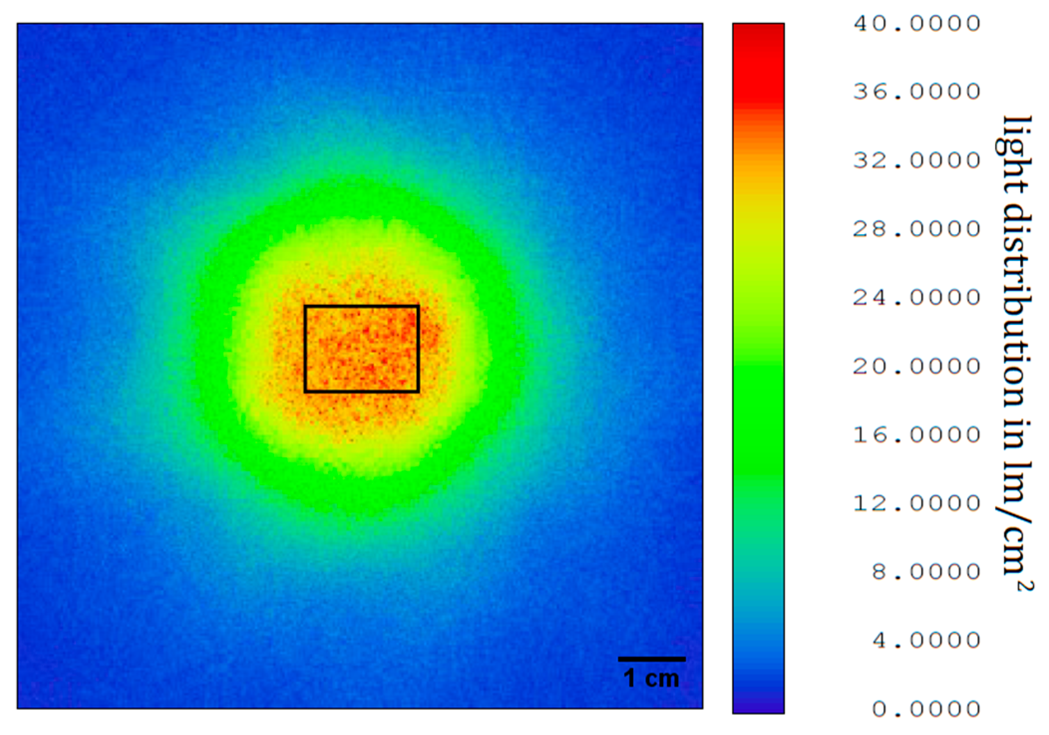
The reflector for shaping of the illuminated area, designed with OpticStudio as mentioned before, was milled and polished from aluminum. The light distribution was measured with a goniometer (PM-1200N-1, Radiant Vision Systems, Redmond, WA, USA) and the data exported again to OpticStudio. Here the light intensity at different distances was calculated. As the output of the illumination unit was measured without polarizer, the intensity had to be multiplied by a factor of 0.5 to obtain a good estimate. Furthermore, the illumination unit was measured with an integrating sphere (50 cm diameter, Mountain Photonics GmbH, Landsberg am Lech, Germany; with connected spectrometer: AvaSpec-2048L, Avantes BV, Apeldoorn, The Niederlande) to determine light intensity and spectral data for color correlated temperature (CCT) and CRI. The CCT of the illumination unit is 6350 K with a CRI of 76. In
Figure 5, the light distribution at a distance of 45 cm from the illumination unit is shown for an imaged area of 10 cm × 10 cm. The overall light flux through this area is 775 lm without or 378.5 lm with polarizer. The light flux on the area of interest (the area which is captured by the camera) at this distance, i.e., 17 mm × 13 mm, is 71.6 lm or 35.8 lm after the polarizer. This results in a polarized illuminance of 162,000 lx. To compare this value, the minimal illuminance for office work spaces in Europe according to work safety regulations is 500 lx [
22]. The measured illuminance from room lighting on the table in our laboratory was 525 lx. If we consider the illuminance in a doctor’s office to be 1000 lx, the illuminance of the area of interest by the presented prototype is 162 times higher. This makes the light situation comparable for every image recorded, as the influence of ambient light on the total illuminance on the area of interest is negligible.
3.2.2. Homogeneous Illumination
A homogeneous illumination is important for both online assessment of an image by the practitioner and digital post processing of the images. In such post processing, often gray scale values are compared to each other and thresholds are used to segment images. This requires comparable gray scale values of the structures to be detected in the whole image. To measure the homogeneity, an image of a homogenous gray scale target (ColorChecker, X-Rite Incorporated, Grand Rapids, MI, USA) was taken.
The average gray scale value of both, the vertical and the horizontal intensity profile is 140.9 with a standard deviation of 2.64 (vertical) corresponding to a relative variance of 4.48% and 2.56 (horizontal) corresponding to a relative variance of 4.76%, respectively. With an average relative variance of 4.62% the illumination is sufficiently homogeneous for the use in a dermatoscopic device.
3.3. Image Colors
3.3.1. Comparable Color Representation
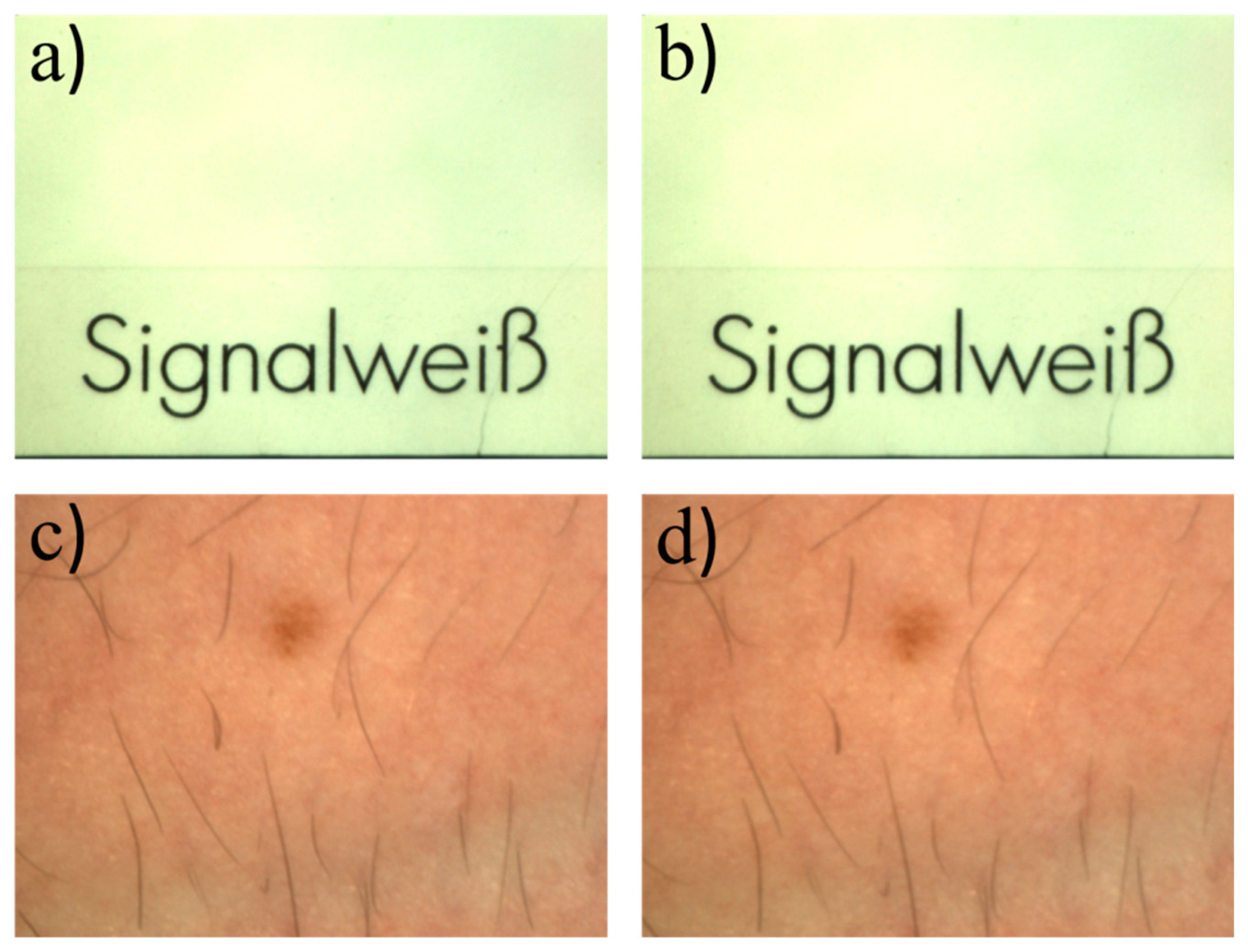
Usually, there is a difference between image colors obtained during examinations and true colors. Due to the relatively small aperture of the camera lens in combination with the ultra-bright LED light source, the system only detects the LED light reflected from the sample under study. This makes the system independent from the ambient light situation and ensures equal exposure times and measurement conditions for every measurement session. In the first row of
Figure 6, two images of the same target but for different lighting conditions are shown. The first image was taken in the dark laboratory. The second was taken while the neon lights of the laboratory were turned on. Comparing gray scale values for equal exposure times shows that there is no significant difference in the pictures. The target used was a signal white (RAL 9003, RAL gGmbH, Bonn, Germany) card from the RAL color standard. In the second row, a picture of human skin is shown under the same lighting conditions. To quantify the difference, the gray scale values from the images in
Figure 6a,b were subtracted from each other. Because small movements/displacements of the target between the images would lead to errors, an image registration was performed first to compensate for that. The average gray scale value of the resulting difference image was determined and is in the range of the noise of the individual images in
Figure 6a,b which was estimated by the standard deviations of the respective gray scale values. The latter were calculated for a 100 pixels x 100 pixels square area in the middle of each image, which shows a homogeneous target. The registration and subtraction was also performed with the images from
Figure 6c,d. The observed differences for this case are slightly larger compared to the first example and can be explained by the residual motion of the skin area between images. That means that the illumination situation is very well controlled and reproducible. If the illumination conditions are known, one calibration is enough to generate a camera color profile and calibrate all pictures taken by that camera. Colors then are comparable to the colors seen by eye and comparable to each other in different images taken with the calibrated system.
Because the light situation is controlled and the measurement parameters are the same for each measurement, the colors of the pictures taken in different examinations are comparable. They can be calculated from the relation between the different color channels.
3.3.2. True Color Rendering
If the system is calibrated once, the colors in the images appear closer to natural colors as can be seen in
Figure 7. It shows images of a standard color reference target (ColorChecker Classic, X-Rite, Grand Rapids, MI, USA). Because the target is too large to fit on one picture, a composite image was assembled from single pictures of each tile of the ColorChecker. The calibration procedure uses the CIE (R,G,B) and LAB color spaces [
23]. It aims at minimizing the color difference between the calibrated image and the optimal colors of the ColorChecker. Color values of the ColorChecker target are given for reference by the distributor.
For a more realistic color perception a calibrated monitor is recommended. The calibration also facilitates the comparison of images obtained from different systems.
The result of the calibration can be seen in
Figure 8.
4. Discussion
The non-contact dermatoscope presented in this work features both an integrated autofocus function calibrated by using an infrared laser-based distance sensor as well as image post-processing. The large working distance is beneficial for routine examinations. If in a future version of the system the distance sensor will be aligned along the optical axis of the camera via a dichroitic mirror, for example, it will be able to focus over an even larger range. Also, a distance-variable image scale would be advantageous and can be included in our system. Furthermore, a color read out tool could be added to the software. With this tool, images taken during different examinations could more easily be compared which could provide, for example, additional information about the blood perfusion. Also, use in therapy monitoring is possible.
The color calibration of our system is not yet optimal as the color values in the calibrated image still deviate from the reference color values. The uncalibrated image is comparably dark. This is because the gain of the camera was set to zero, so that the images can more easily be compared after image noise reduction. Also, the exposure time was set to 75 ms as a compromise between image brightness and exposure time to avoid motion blur. An even brighter light source would be advantageous in this regard. Another option would be to track the gain for the images taken and include this value in the calibration algorithm.
With regard to CRI requirements, halogen light sources and high pressure xenon lamps, for example, can have CRI values of 100 and 93, respectively [
24]. As we use an LED with a more discrete emission spectrum, the CRI cannot directly be compared with CRI of the more continuously emitting light sources mentioned above. The reason for this is, that small changes in a discrete spectrum can result in large changes in the CRI which does not correlate with the changes in color representation as perceived by an human observer or a camera [
25]. Also, the spectral acceptance of the sensor employed, i.e., the camera system, has to be taken into account. As even the light situation in examination rooms can alter because of, for example, the daytime, no exact color matching is needed in this case. It is more important to ensure comparable colors in every picture taken by the system. The light source and image algorithms can further be improved by spectral tuning to enhance visibility of different features relevant for diagnostics in dermatology [
26].
Finally, the hardware components of the system can be made more compact, so that the it can serve as a module in an automated skin-screening device. In such a scheme the patient lies on a medical lounger and an automated arm equipped with suitable imaging systems takes overview pictures of the skin and identifies nevi and other areas relevant to dermatology. Subsequently, the system described in this work would take high-resolution images of the selected skin areas. In case of nevi, an algorithm that evaluates the ABCDE criteria could then make a risk analysis so that the physician only needs to examine the suspicious ones in more detail. In further versions, external image analysis from outside the examination room could be implemented as well as deep learning approaches for fast and essentially real-time analysis as pointed out in [
27].
5. Conclusions and Outlook
In this work, we present a prototype of a non-contact dermatoscope with a built-in autofocus system. The auto-focus is based on a liquid lens in combination with an infrared laser distance sensor. This setup is sufficiently fast for dermatoscopy enabling a focus refresh rate of 30 Hz for image acquisition, which is double the maximal frame rate of the camera. The resolution of the dermatoscopic system is slightly lower than the resolution of the system without the liquid lens, but it is still within the required minimal resolution of 30 µm. In the current alignment of the components, the system is optimized for a working distance of 45 cm ± 3 cm. If the surface to be examined is not strongly curved (over the range of the depth of field) the system delivers sharp images at even larger distances as the infrared laser spot is reflected on the image plane. The prototype is largely independent of the ambient light due to its ultra-bright LED-light source illuminating the area of interest on the target at a distance of 45 cm with a luminous flux of 35.8 lm, which is equivalent to 162,000 lx. This makes images taken under different ambient light conditions comparable. The system also allows for color calibration to obtain more realistic color representation
In the next step, the prototype will be tested in a clinical environment. This could reveal further diagnostic advantages. A study will be designed to collect a larger set of images from skin lesions correlated to specific diagnostic data. The focus will be placed on a number of common inflammatory diseases in order to identify (new) diagnostic features that are revealed by the dermatoscopic images and to better evaluate the diagnostic potential of the non-contact remote approach.
Author Contributions
Conceptualization, D.F. and M.W.; Funding acquisition, B.R.; Investigation, E.D. and D.F.; Project administration, B.R., Resources, A.H., T.W. and B.R.; Software, D.F.; Supervision, M.W. and B.R.; Writing—original draft, D.F.; Writing—review & editing, D.F., M.W. and B.R.
Funding
This project is funded by the Lower Saxony Ministry for Culture and Science (MWK) through the program Tailored Light and the Deutsche Forschungsgemeinschaft (DFG, German Research Foundation) under Germany’s Excellence Strategy within the Cluster of Excellence PhoenixD (EXC 2122, Project ID 390833453).
Conflicts of Interest
The authors declare no conflicts of interest.
References
- MacKIE, R.M. An aid to the preoperative assesment of lesions of the skin. Br. J. Dermatol. 1971, 85, 232–238. [Google Scholar] [CrossRef]
- Pehamberger, H.; Steiner, A.; Wolff, K. In vivo epiluminescence microscopy of pigmented skin lesions. I. Pattern analysis of pigmented skin lesions. J. Am. Acad. Dermatol. 1987, 17, 571–583. [Google Scholar] [CrossRef]
- Steiner, A.; Pehamberger, H.; Wolff, K. In vivo epiluminescence microscopy of pigmented skin lesions. II. Diagnosis of small pigmented skin lesions and early detection of malignant melanoma. J. Am. Acad. Dermatol. 1987, 17, 584–591. [Google Scholar] [CrossRef]
- Optotechnik, H. HEINE Optotechnik|Home. Available online: https://www.heine.com/en_GB/home/ (accessed on 27 May 2019).
- 3Gen. The Worldwide Leader in Handheld Dermoscopy for Skin Cancer Detection. Available online: https://dermlite.com/ (accessed on 27 May 2019).
- Nachbar, F.; Stolz, W.; Merkle, T.; Cognetta, A.B.; Vogt, T.; Landthaler, M.; Bilek, P.; Braun-Falco, O.; Plewig, G. The ABCD rule of dermatoscopy. J. Am. Acad. Dermatol. 1994, 30, 551–559. [Google Scholar] [CrossRef]
- Abbasi, N.R.; Shaw, H.M.; Rigel, D.S.; Friedman, R.J.; McCarthy, W.H.; Osman, I.; Kopf, A.W.; Polsky, D. Early diagnosis of cutaneous melanoma: revisiting the ABCD criteria. JAMA 2004, 292, 2771–2776. [Google Scholar] [CrossRef] [PubMed]
- Meinhardt-Wollweber, M.; Heratizadeh, A.; Basu, C.; Günther, A.; Schlangen, S.; Werfel, T.; Schacht, V.; Emmert, S.; Haenssle, H.A.; Roth, B. A non-contact remote digital dermoscope to support cancer screening and diagnosis of inflammatory skin disease. Biomed. Phys. Eng. Express 2017, 3, 55005. [Google Scholar] [CrossRef]
- Bassoli, S.; Seidenari, S. Benefits of polarized versus nonpolarized dermoscopy. Expert Rev. Dermatol. 2010, 5, 17–21. [Google Scholar] [CrossRef]
- Drexler, W.; Fujimoto, J.G. (Eds.) Optical Coherence Tomography: Technology and Applications, 2nd ed.; Springer: Berlin, Germany, 2015. [Google Scholar]
- Varkentin, A.; Mazurenka, M.; Blumenroether, E.; Meinhardt-Wollweber, M.; Rahlves, M.; Broekaert, S.M.C.; Schäd-Trcka, S.; Emmert, S.; Morgner, U.; Roth, B. Comparative study of presurgical skin infiltration depth measurements of melanocytic lesions with OCT and high frequency ultrasound. J. Biophotonics 2017, 10, 854–861. [Google Scholar] [CrossRef] [PubMed]
- Varkentin, A.; Mazurenka, M.; Blumenröther, E.; Behrendt, L.; Rahlves, M.; Meinhardt-Wollweber, M.; Morgner, U.; Roth, B. Trimodal system for in vivo skin cancer screening with combined optical coherence tomography-Raman and co-localized optoacoustic measurements. J. Biophotonics 2018, 11. [Google Scholar] [CrossRef]
- De Oliveira Barcaui, E.; Carvalho, A.C.P.; Valiante, P.M.N.; Barcaui, C.B. High-frequency ultrasound associated with dermoscopy in pre-operative evaluation of basal cell carcinoma. An. Bras. Dermatol. 2014, 89, 828–831. [Google Scholar] [CrossRef] [Green Version]
- FotoFinder Systems GmbH, “FotoFinder: Bodystudio ATBM. Available online: https://www.fotofinder.de/en/products/bodystudio/atbm/ (accessed on 27 May 2019).
- Ragaz, A.; Ackerman, A.B. Evolution, maturation, and regression of lesions of lichen planus. New observations and correlations of clinical and histologic findings. Am. J. Dermatopathol. 1981, 3, 5–25. [Google Scholar] [CrossRef] [PubMed]
- DIN—German Institute for Standardization, DIN 5035-3. Artificial Lighting—Part 3: Lighting of Health Care Premises. Available online: https://www.beuth.de/de/norm/din-5035-3/88503242 (accessed on 27 May 2019).
- Langlois, N.E.; Gresham, G.A. The ageing of bruises: A review and study of the colour changes with time. Forensic Sci. Int. 1991, 50, 227–238. [Google Scholar] [CrossRef]
- Stephenson, T.; Bialas, Y. Estimation of the age of bruising. Arch. Dis. Child. 1996, 74, 53–55. [Google Scholar] [CrossRef] [PubMed]
- Groner, W.; Winkelman, J.W.; Harris, A.G.; Ince, C.; Bouma, G.J.; Messmer, K.; Nadeau, R.G. Orthogonal polarization spectral imaging. A new method for study of the microcirculation. Nat. Med. 1999, 5, 1209–1212. [Google Scholar] [CrossRef] [PubMed]
- Jacques, S.L.; Roman, J.R.; Lee, K. Imaging superficial tissues with polarized light. Lasers Surg. Med. 2000, 26, 119–129. [Google Scholar] [CrossRef]
- Jacques, S.L.; Ramella-Roman, J.C.; Lee, K. Imaging skin pathology with polarized light. J. Biomed. Opt. 2002, 7, 329–340. [Google Scholar] [CrossRef] [PubMed]
- DIN—German Institute for Standardization, DIN 12464-1 (2011-08): Light and Lighting—Lighting of Work Places—Part 1: Indoor Work Places. Available online: https://www.beuth.de/de/norm/din-en-12464-1/136885861 (accessed on 27 May 2019).
- János, S. (Ed.) Colorimetry: Understanding the CIE System; John Wiley & Sons, Ltd.: Hoboken, NJ, USA, 2007; ISBN 978-0-470-04904-4. [Google Scholar]
- Hunt, R.W.G. The Reproduction of Colour; John Wiley & Sons, Ltd.: Hoboken, NJ, USA, 2004. [Google Scholar]
- Narendran, N.; Deng, L. Color rendering properties of LED light sources. Proc. SPIE 2002, 4776, 61–67. [Google Scholar]
- Basu, C.; Schlangen, S.; Meinhardt-Wollweber, M.; Roth, B. Light source design for spectral tuning in biomedical imaging. J. Med. Imaging 2015, 2, 44501. [Google Scholar] [CrossRef] [PubMed] [Green Version]
- Haenssle, H.A.; Fink, C.; Schneiderbauer, R.; Toberer, F.; Buhl, T.; Blum, A.; Kalloo, A.; Hassen, A.B.H.; Thomas, L.; Enk, A.; et al. Man against machine: Diagnostic performance of a deep learning convolutional neural network for dermoscopic melanoma recognition in comparison to 58 dermatologists. Ann. Oncol. Off. J. Eur. Soc. Med Oncol. 2018, 29, 1836–1842. [Google Scholar] [CrossRef] [PubMed]
© 2019 by the authors. Licensee MDPI, Basel, Switzerland. This article is an open access article distributed under the terms and conditions of the Creative Commons Attribution (CC BY) license (http://creativecommons.org/licenses/by/4.0/).

 and
and 


