Image Transmission through Scattering Media Using Ptychographic Iterative Engine

1
Shanghai Institute of Optics and Fine Mechanics, Chinese Academy of Sciences, Shanghai 201800, China
2
Center of Materials Science and Optoelectronics Engineering, University of Chinese Academy of Sciences, Beijing 100049, China
*
Author to whom correspondence should be addressed.
Appl. Sci. 2019, 9(5), 849; https://0-doi-org.brum.beds.ac.uk/10.3390/app9050849
Submission received: 16 January 2019
/
Revised: 17 February 2019
/
Accepted: 22 February 2019
/
Published: 27 February 2019
(This article belongs to the Special Issue Recent Advances in Statistical Optics and Plasmonics)
Abstract
:Random scattering media prevent light information from directly transmitting through, them as the photons will deviate from their original propagation directions due to the inhomogeneity of the refractive index distribution in scattering media. Based on recent developed methods, light information transmission through scattering media is realized using a memory effect. However, the memory effect range limits it to a small field of view. To enlarge the field of view, in this article, we propose to use the ptychographic iterative engine to deliver information through scattering media. We experimentally demonstrate that the proposed method can deliver images beyond the memory effect range through the scattering layer with outstanding imaging performance.
1. Introduction
When the information-bearing light is disturbed by scattering media such as fog, haze [1], biological tissues [2], and the surfaces of walls [3], a common optical imaging system will fail to realize regular pixel-to-pixel mapping between the object space and the image space. The inherent reason is that the wavefront that carries the object information undergoes random disturbance as it propagates owing to the inhomogeneity of the refractive index distribution of the scattering media. To solve this problem, several methods have been proposed in recent years to transmit, focus, and image through scattering media based on different application scenarios [4,5,6,7,8,9,10,11,12]. Among them, transmission of image information through scattering media has received much attention. Typically, this task can be achieved with the help of the transmission matrix of the system [4], where a precise measurement of the system should be implemented. Wave front shaping [5] and phase conjugation [6] can be used when a reference point or object should be known a priori. Single pixel detection could be applied if the object could be projected with a series of fringe patterns [7,8].
On the other hand, the correlation property of the light field that passes through the scattering medium has also been explored to reconstruct the image of the object behind it. New progress in the memory effect makes it possible to image three-dimensional objects [13,14], retrieve spectral information [15], and work under noisy conditions [16,17]. The fundamental theory of the memory effect was developed by Feng et al. [18] and Freund [19]. The basic idea of this method is that for a scattering medium, there exists a maximum field-of-view (FOV) called the memory effect range, which is determined by the optical thickness of the medium. Within this range, the system is approximately translation-invariant, with the impulse response having the form of a speckle . The autocorrelation of the speckle is a sharp-peaked function [11,12] with a uniform background term. Therefore, with incoherent illumination, the camera image can be written as the convolution of the target function with the point spread function by:
where the symbol ∗ denotes convolution and is the two dimensional spatial coordinate. The autocorrelation of the camera image reveals that:
where the symbol ⋆ stands for correlation and C a constant value. Therefore, if the object is within the memory effect range, then the autocorrelation of the collected speckles is equivalent to the autocorrelation of the object. From the autocorrelation, a diffraction limited reconstruction of the target can be reconstructed using phase retrieval techniques [11,12,20].
However, the memory effect imposes a limit of the FOV that can be achieved by this method [19]: , where L denotes the effective optical thickness of the scattering medium. For example, the FOV of a 0.5 mm thick chicken breast slice with the optical thickness being equal to 7 μm is approximately 1.4 degrees when illuminated by a laser with a wavelength of 532 nm [12]. Here, we propose an approach to obtain large FOV imaging through scattering media with the help of a ptychographic iterative engine (PIE). Additionally compared with a conventional iterative phase retrieval algorithm, PIE is more robust without twin images and has a faster and more reliable convergence performance [21,22,23].
2. Methods
The proposed method uses a probe aperture to scan the target and a camera to record the speckle intensity which is formed after the light from the probed area passes through a scattering medium. The size of the probe beam is small enough to make sure it is within memory effect range. When a raster scan is complete, the camera captures a series of speckle patterns:
where denotes the target which is much larger than the memory effect range, is the probe aperture translated by a known amount , is the point spread function in the corresponding area of , and for the simplicity of description. The point spread functions in different probe apertures is unnecessarily correlated. In this way, we could record a series of speckle patterns carrying information about the target at different local areas. The proposed method is to calculate the autocorrelation functions directly from these speckle patterns, the Fourier transforms of which are actually the power spectra of each probed part of the target:
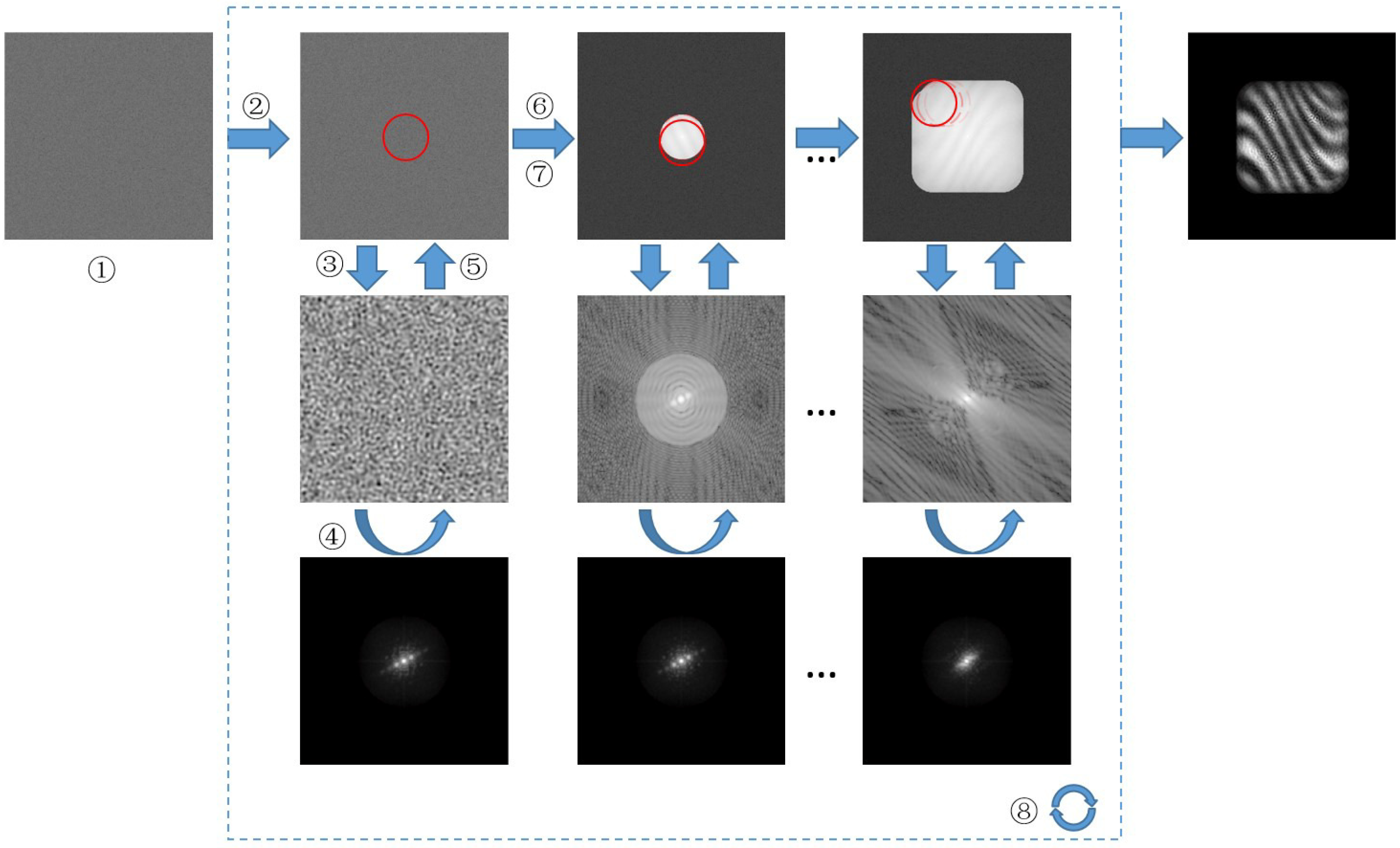
where stands for the Fourier transform and is the two-dimensional spatial frequency coordinate. Equation (4) indicates that from the collected speckle patterns, one can obtain the far-field diffraction patterns corresponding to the selected regions of the target. From these patterns, the proposed method reconstructs the target image by PIE. The framework of the PIE algorithm is similar to the conventional one [21,22]. Figure 1 shows the procedure, which is composed of the following steps:
- ①
- The algorithm starts with an initial estimation of the target function . In our implementation, the initial guess was a real and non-negative random matrix.
- ②
- Multiply the estimated target function obtained at the iteration with the aperture function at the current position:where is the estimated object at iteration, is the probe aperture as we know prior, and is the estimated probed object at iteration.
- ③
- Fourier transform the result calculated at step ②.
- ④
- Replace the magnitude of the Fourier spectrum obtained at step ③ with the measured data and keep the phase unchanged:where is calculated from Equation (4) from the collected speckle patterns.
- ⑤
- Inversely Fourier transform the updated spectrum back to the object plane:where is the inverse Fourier transform.
- ⑥
- Update the target image within probe aperture via:where is a feedback parameter to controls the amount of importance of the result from previous step in the algorithm.
- ⑦
- Move to the next aperture position and repeat steps ②–⑥.
- ⑧
- Repeat steps ②–⑦ and sequentially update the object function until the algorithm converges.
The convergence can be monitored by the correlation coefficient between and by
where and are the mean value of and . and are the stand division of and , respectively. We can stop the iteration procedure when is greater than a threshold value or the number of iteration reaches a predefined value. To successfully implement the PIE algorithm, the adjacent probe aperture should have certain overlap. When the overlap is increased to , high quality image of the target can be reconstructed according to our investigation. A more detailed discussion of how the overlapping ratio influences the imaging performance can be found in Reference [24]. In our method, as the object is incoherently illuminated, the PIE algorithm is just used to reconstruct the intensity of the target image. The study of reconstructing the phase or depth information behind scattering media can be found in References [13,25].
3. Experiment and Results
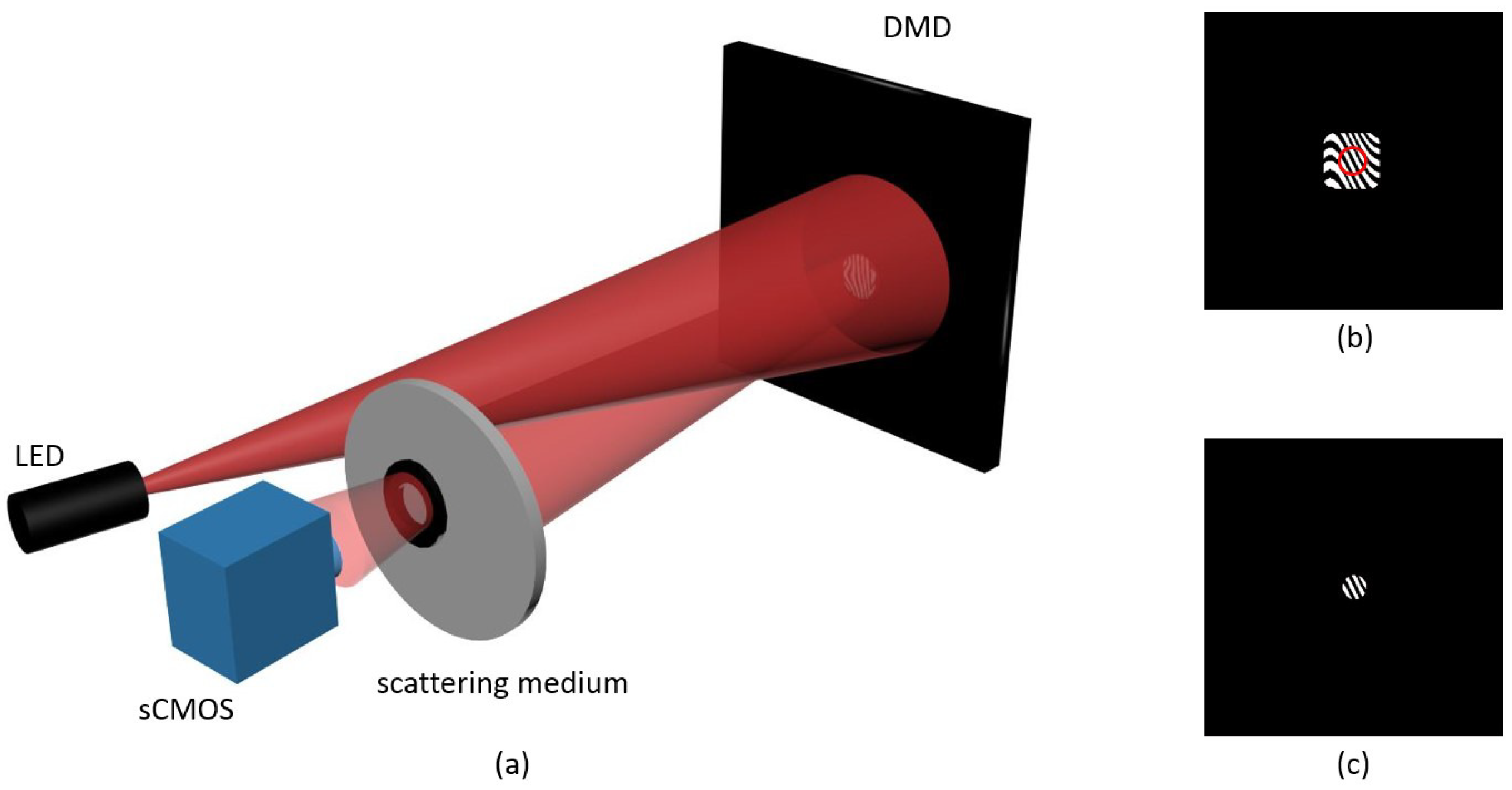
To demonstrate our method, we employed a simplified setup as shown in Figure 2a. In this experimental setup, a narrowband LED emitting at nm was used as the incoherent illumination source. The expanded uniformed beam was then shone onto a digital micro-mirror device (DMD) from Texas Instruments (DLP 9500). In order to demonstrate the performance of the proposed technique for imaging beyond the memory effect range, we should use a target image with sufficient large lateral extension and diffract the incoming beam in large angles. The target image we selected then was a binary fringe pattern of pixels in size, as shown in Figure 2b. As the pixel size of our DMD is 10.8 μm, this corresponds to the physical area of the target about mm2, or, in equivalent, 0.0037 radian in terms of FOV. Displaying the target image on the DMD offers the advantage that we do not need to mechanically scan the target stepwise so as to release the mechanical instability. Instead, we can use an aperture displayed on the DMD as well and perform a virtual scanning by changing its position. The size of the aperture, d, should be small enough to ensure it is within the range of the memory effect , where z is the distance between the target and the nearest surface of the scattering medium; cm in our setup, and the FOV of the medium was 0.0015 radian as we measured. This allows us to use a probe aperture with the size of μm in our experiments. The beam reflected by the DMD is then passed through a thick ground glass, and captured by an sCMOS camera (PCO Edge 4.2), which was placed 12 cm away from the back surface of the scattering medium. The scanning interval of the aperture was about 120 μm in our experiment, so that the camera captured 121 diffraction patterns after the aperture scanned across the whole target image.
The collected speckles were divided into a series of sub-images with the size of pixels. This size was chosen so that most information of the autocorrelation of probed object can be covered [20]. Owing to the ergodic property of the speckle [19], the spatial averaging of the autocorrelation functions calculated from the sub-images is in principle equivalent to the time averaging of the speckle images, which is equal to that of the target according to Equation (2). This also holds for the energy spectrum density. Therefore, for each part of the target selected by the aperture , , the suppression of noise can be achieved by spatially averaging the autocorrelation of all the sub-images from the corresponding speckle image. The estimated 121 energy spectrum densities were then fed into our PIE algorithm. After 30 times of iteration, the improvement of the reconstructed image quality becomes negligible as the iteration continues. The correlation coefficient is 0.998 in our study. It took 12 s in total on a common personal computer (with the Intel Core i5 CPU and 8 GB memory, implemented in Matlab R2014a platform) without parallel processing. In this way, we reconstructed an image of pixels in size with 121 numbers of the patterns projected on the object. A similar technique was proposed in References [7,8]. However, in their methods, they need to project a plenty of fringe patterns on the object. Usually. thousands of fringe patterns are needed to reconstruct even a pixels image. Using the memory effect of scattering media, the fringe patterns projected on the scattering media are dramatically reduced in our method.
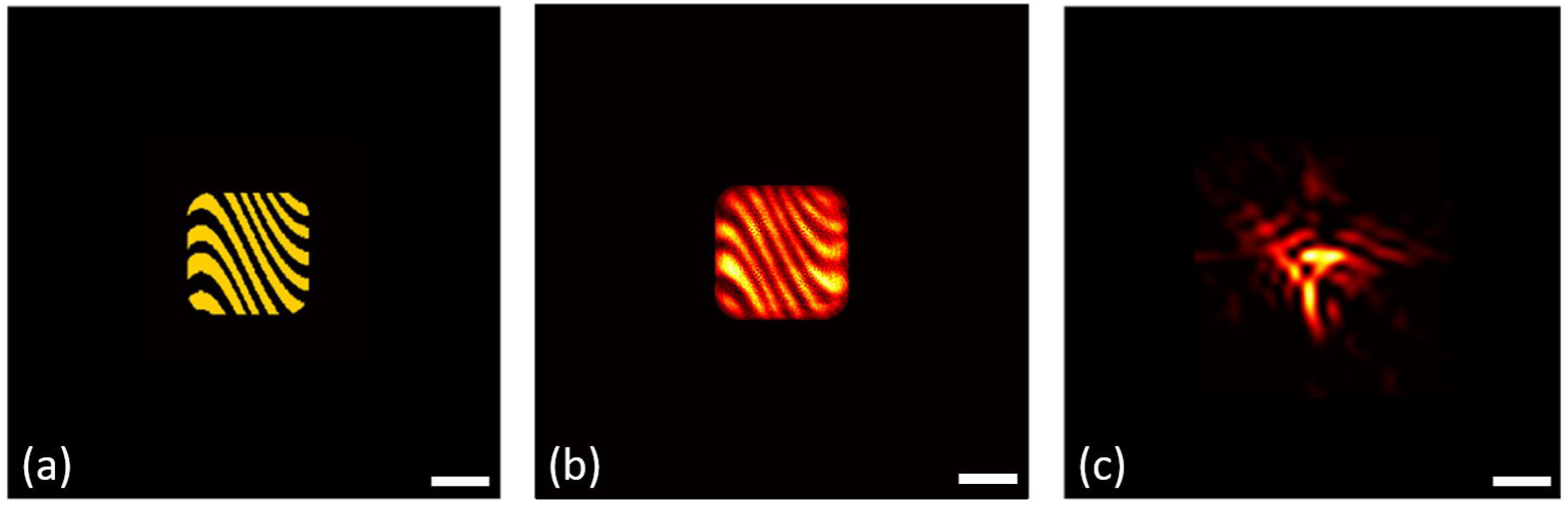
The main experimental results are illustrated in Figure 3. In Figure 3a, we plotted the ground truth target image, which was loaded on the DMD. The reconstructed image is shown in Figure 3b. It is clearly seen that the target can be reconstructed using the proposed approach. In principle, the resolution in this case is limited by several factors. For example, the size of the illumination spot on the scattering medium determines the size of the speckle grand, which should be large enough to be resolvable by the camera. When this is met, the resolution is mainly determined by the effective diameter, , of the variable iris placed between the scattering medium and the camera, which is given by [19]. In our setup, mm, giving a theoretical resolution μm. More effects of the variable iris on the image performance can be found in References [3,12].
As the angular range of the total scanning area to the scattering medium is about 0.0037 radian, about two folds of the memory effect range, the conventional memory-effect-based method that directly uses the hybrid input–output algorithm (HIO) [11,12] will fail to recover the target image. Indeed, we plotted a typical reconstructed image in Figure 3c. Nothing about the target can be recovered but noise. We calculated the correlation coefficient of the two reconstructed images with respect to the target. The associated values for Figure 3b,c are 0.74 and 0.42, respectively.
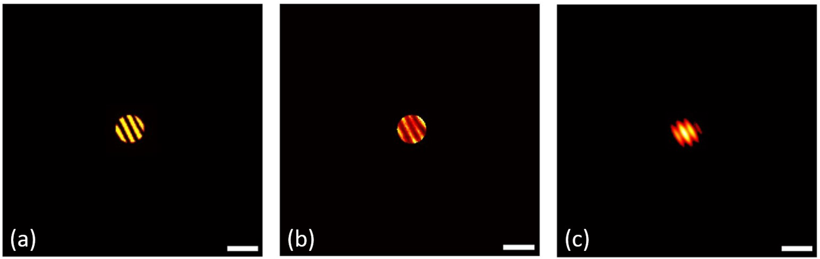
Within the range of memory effect, the captured speckle intensity is highly correlated with the target image [18,19]. It is therefore expected that both the conventional phase-retrieval algorithm [11,12] and the proposed PIE-based algorithm can reconstruct the target image. In comparison to the conventional algorithm, however, the proposed method uses strong support constraints (shape and position of the probe aperture) at the target plane and therefore should be more robust against noise and false solutions [26]. Indeed, when we used only one of the captured speckle patterns for reconstruction, we received the reconstructed images using these two algorithms, respectively, shown in Figure 4b,c. It is clearly seen that the shape and contrast of the reconstructed image using the PIE algorithm resembles that of the target, which is shown in Figure 4a. The correlation coefficients for Figure 4b,c with respect to Figure 4a are 0.79 and 0.69, respectively.
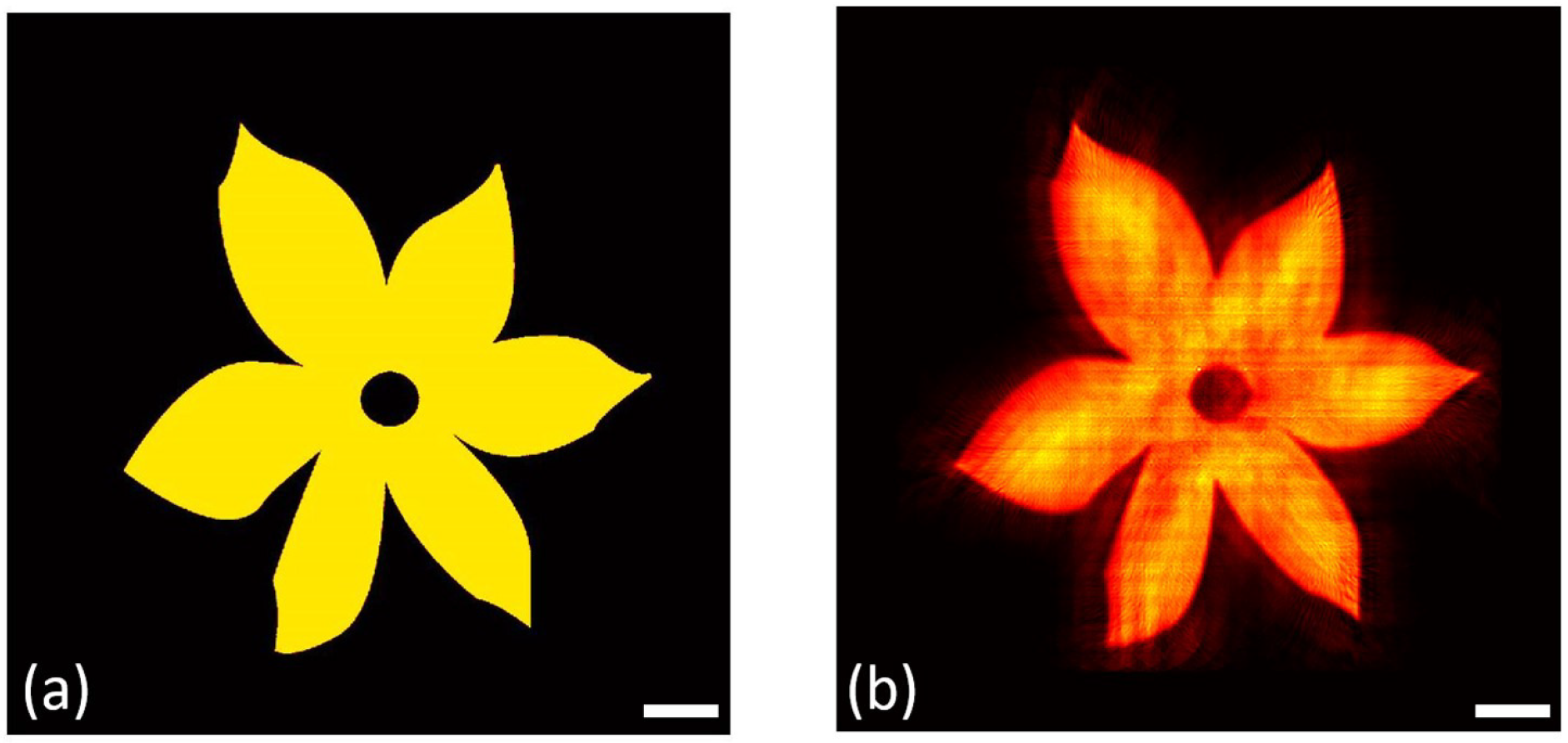
On the other hand, if the object rather than the probe aperture can be scanned, as in the case that the object behind the scattering medium is self-illuminating and moving, the FOV can be further enlarged. To demonstrate this concept, we digitally translated the target with respect to fixed apertures, both of which were displayed on the DMD in a similar optical setup to that shown in Figure 2. The size of the aperture was 1.4 mm so that the FOV would be within the range of the memory effect. We translated a target of 8 mm × 8 mm (shown in Figure 5a) along the x and the y directions stepwise across the aperture. Twenty-three steps with a step interval of mm were translated in both directions, resulting in sub-images that were taken by the camera. Using the proposed algorithm, we can reconstruct the image of the extended target within 1 min. The result is shown in Figure 5b, and the correlation coefficient is 0.93, suggesting that the image has been faithfully reconstructed.
4. Discussion and Conclusions
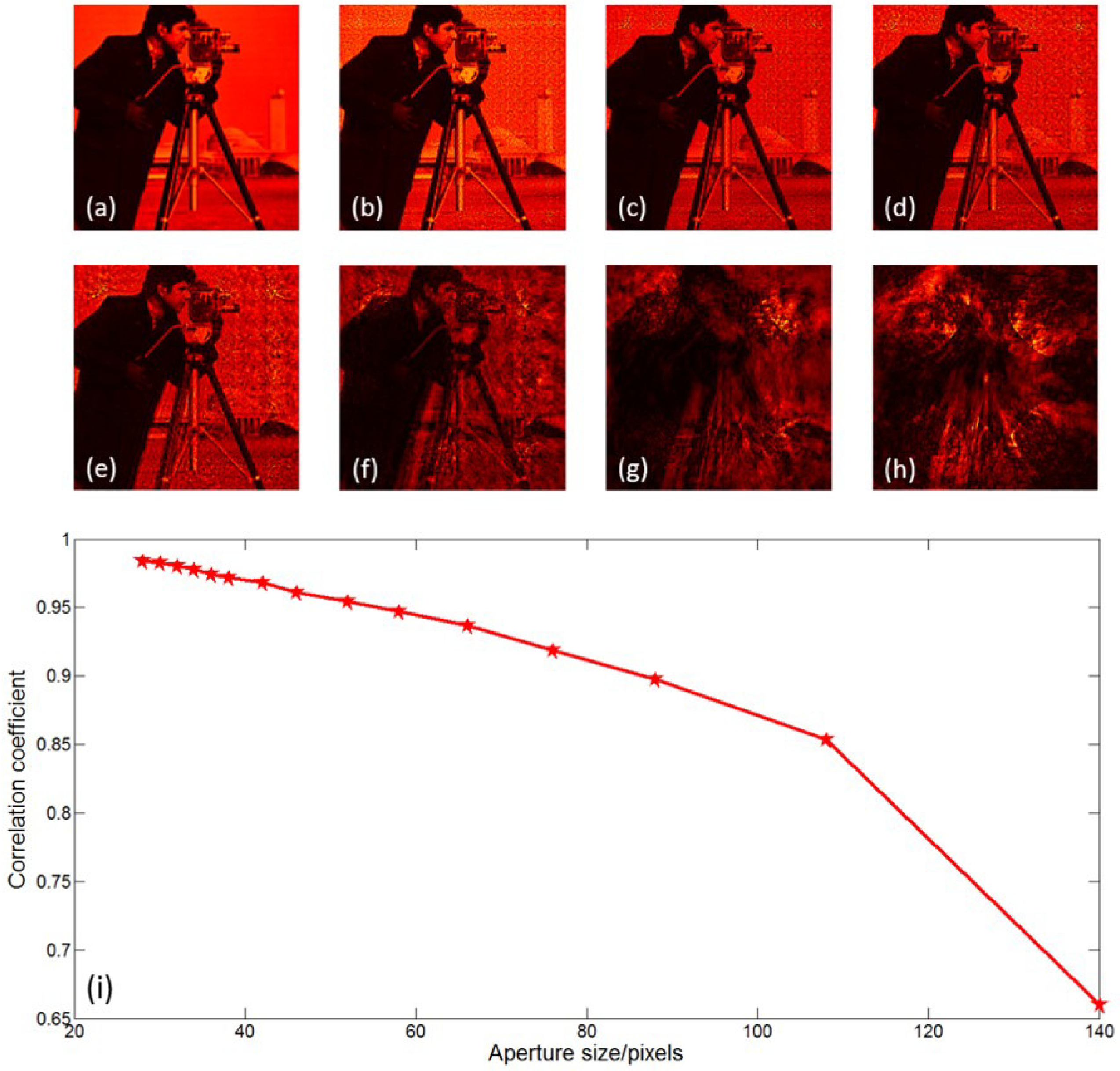
Next, we show how the aperture size affects the reconstruction performance using a simulation. The target object we used was the ’Cameraman’ with the size of pixels. We zero padded it to pixels in our simulations. We scanned the object with a circular aperture, the diameter of which varied from 28 to 140 pixels. The overlapping ratio between two neighboring apertures in the course of scanning was fixed to be . The scattering layer was a ground glass with the same structure. For simplicity, we supposed that the size of the target is within the range of the memory effect of the ground glass. Then, the probed image in each scan can be expressed as the convolution of the part of the target within the probe aperture with the point spread function of the ground glass. The speckle patterns used in our simulation were obtained by numerically calculating Equation (3), the convolution between the target and a series of , which were experimentally collected in the lab. After feeding all the speckle patterns into the proposed algorithm, we obtained some typical reconstructed images, as shown in Figure 6b–h. Note that we just used the center pixels of the reconstructed images in order to reduce the edge effect. We calculated the correlation coefficient between the target and the reconstructed image in all these cases, and the result is plotted in Figure 6i. The result suggested that the reconstruction performance of the proposed method is affected by the size of the probe aperture. The smaller the aperture, the better the reconstructed image quality.
In our opinion, this result is mainly induced by two factors. First, a smaller probe aperture leads to a more compact constraint to the algorithm, which increases the robustness of the reconstruction. Second, in the speckle pattern, the number of independent realizations of the speckles is proportional to the area of the probed object. Thus, the use of smaller apertures results in higher speckle contrast [12].
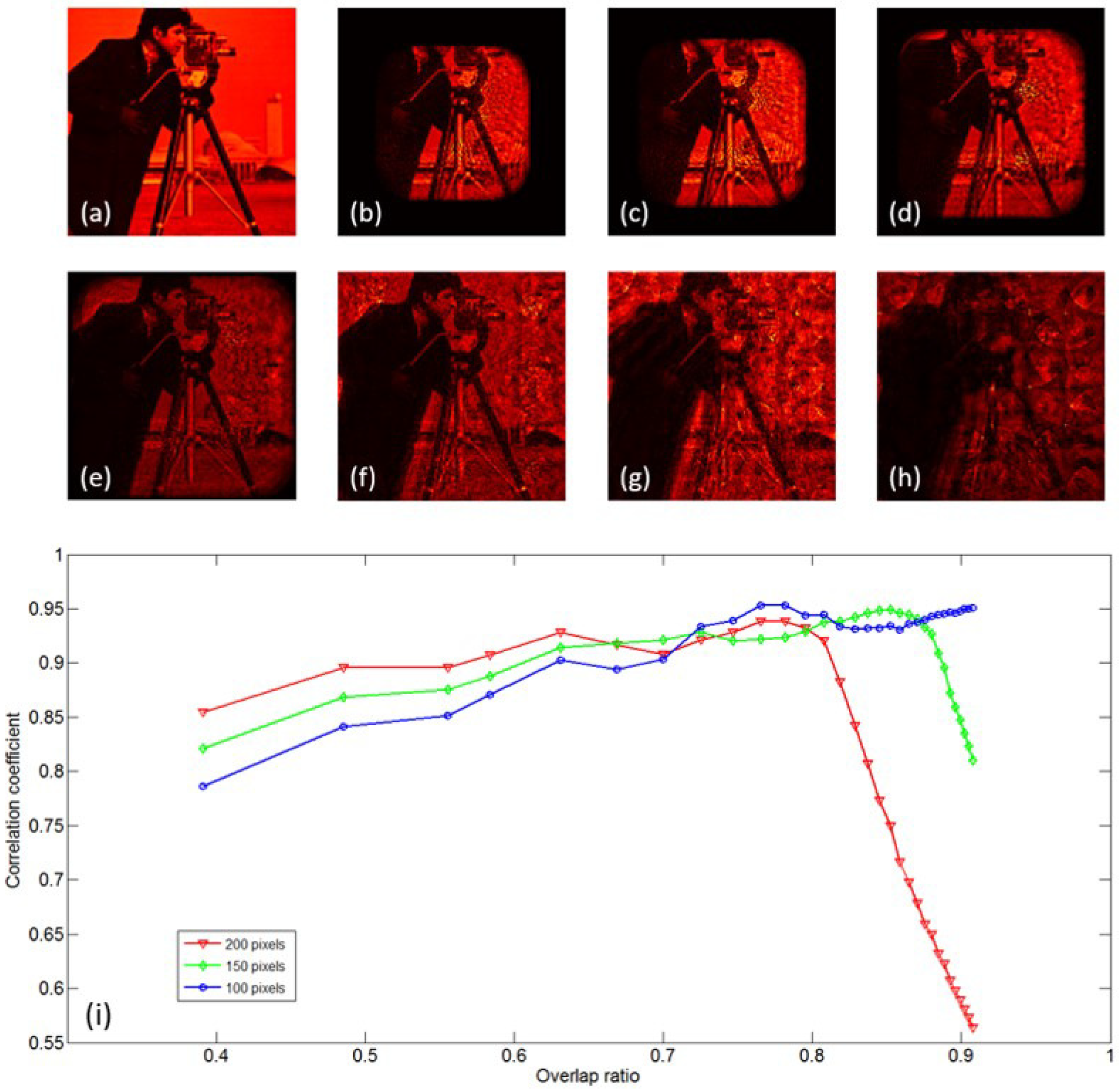
We then made a simulation to show how the overlap ratio can influence the image performance. In this simulation, the diameter of the probe aperture was 66 pixels, and the overlap ratio varied from 39% to 91%. We moved the probe apertures to 255 different positions to show how large the effective area can be scanned in a given time. Some typical reconstructed images are shown in Figure 7b–h.
The correlation coefficients between the target and the recovered results with center pixels are demonstrated in Figure 7i with a red line. From the figure, we find that if the overlap ratio is less than 80%, the higher overlap ratio will lead to a better imaging performance. However, when the overlap ratio reaches a very high value, the reconstructed image quality will degrade, as the effectively scanned area will be reduced. We also calculated the correlation coefficient between the target and the recovered results with center pixels (indicated with green line in Figure 7i) and pixels (indicated with blue line in Figure 7i). The results indicate that a better reconstruction of the central part will come out with a higher overlap ratio.
However, in a practical application, small probe apertures as well as a high overlap ratio might not be suggested, as some more factors should be taken into consideration, such as the imaging speed, illumination power, aberrations, and noise. Therefore, the specific choice of these parameters should be adjusted according to the specific motivation.
In conclusion, we have demonstrated the use of the PIE algorithm for transmitting images through scattering media. We proposed to use a small probe aperture to scan the object with multiple shots and use the PIE algorithm to reconstruct the object behind the scattering media. The FOV of the reconstructed image was then enlarged. Additionally, the advantage of the PIE algorithm makes it possible to overcome the problems of conventional phase retrieval techniques and get outstanding image performance. The PIE algorithm we adopted in our study needs accurate knowledge of the shape and positions of the probe apertures, which are controllable in our proof-of-concept experiments, as the probe was implemented by a DMD. In practical application, however, these parameters may not be accurately known. As a result, the reconstructed image will suffer from noise and reduction of resolution. One should bear in mind that many studies have been carried out to improve the PIE algorithm [27,28,29].
The proposed method can be applied in particular to situations where the target can be illuminated with desired patterns—for example, in the application of aircraft landing in cloudy days [30]. In cases where signal lights on the runway can be switched on and off in sequence, it analogously performs a scan of the runway with a ‘probe’ beam whose aperture equals to the size of the signal light.
Author Contributions
Conceptualization, G.S. and G.L.; methodology, W.Y. and H.W.; software, G.L. and H.W.; validation, W.Y.; formal analysis, G.S.; investigation, G.L.; resources, G.L.; writing—original draft preparation, G.L.; writing—review and editing, G.S., W.Y. and H.W.; visualization, G.L.; supervision, G.S.; project administration, G.S.; funding acquisition, G.S.
Funding
This work was supported by the Key Research Program of Frontier Sciences, Chinese Academy of Sciences (QYZDB-SSW-JSC002), Sino-German Center for Sino-German Cooperation Group (Grant No. GZ1391), National Natural Science Foundation of China (Nos. 61705241) and natural Science Foundation of Shanghai (No. 17ZR1433800).
Conflicts of Interest
The authors declare no conflict of interest.
Abbreviations
The following abbreviations are used in this manuscript:
| DMD | digital micro-mirror device |
| FOV | field-of-view |
| HIO | hybrid-input-output |
| PIE | ptychographical iterative engine |
References
- Schechner, Y.Y.; Narasimhan, S.G.; Nayar, S.K. Polarization-based vision through haze. Appl. Opt. 2003, 42, 511–525. [Google Scholar] [CrossRef] [PubMed]
- Andersson-Engels, S.; Jarlman, O.; Berg, R.; Svanberg, S. Time-resolved transillumination for medical diagnostics. Opt. Lett. 1990, 15, 1179–1181. [Google Scholar] [CrossRef] [PubMed]
- Freund, I. Looking through walls and around corners. Physica A 1990, 168, 49–65. [Google Scholar] [CrossRef]
- Popoff, S.; Lerosey, G.; Carminati, R.; Fink, M.; Boccara, A.; Gigan, S. Measuring the transmission matrix in optics: An approach to the study and control of light propagation in disordered media. Phys. Rev. Lett. 2010, 104, 100601. [Google Scholar] [CrossRef] [PubMed]
- Vellekoop, I.M. Feedback-based wavefront shaping. Opt. Express 2015, 23, 12189–12206. [Google Scholar] [CrossRef] [PubMed]
- Wang, Y.M.; Judkewitz, B.; DiMarzio, C.A.; Yang, C. Deep-tissue focal fluorescence imaging with digitally time-reversed ultrasound-encoded light. Nat. Commun. 2012, 3, 928. [Google Scholar] [CrossRef] [PubMed] [Green Version]
- Tajahuerce, E.; Durn, V.; Clemente, P.; Irles, E.; Soldevila, F.; Andrs, P.; Lancis, J. Image transmission through dynamic scattering media by single-pixel photodetection. Opt. Express 2014, 22, 16945–16955. [Google Scholar] [CrossRef] [PubMed] [Green Version]
- Gong, W.; Han, S. Correlated imaging in scattering media. Opt. Lett. 2011, 36, 394–396. [Google Scholar] [CrossRef] [PubMed]
- Huang, D.; Swanson, E.A.; Lin, C.P.; Schuman, J.S.; Stinson, W.G.; Chang, W.; Hee, M.R.; Flotte, T.; Gregory, K.; Puliafito, C.A.; et al. Optical coherence tomography. Science 1991, 254, 1178–1181. [Google Scholar] [CrossRef] [PubMed] [Green Version]
- Zhang, Y.; Situ, G.; Pedrini, G.; Wang, D.; Javidi, B.; Osten, W. Application of short-coherence lensless Fourier-transform digital holography in imaging through diffusive medium. Opt. Commun. 2013, 286, 56–59. [Google Scholar] [CrossRef]
- Bertolotti, J.; van Putten, E.G.; Blum, C.; Lagendijk, A.; Vos, W.L.; Mosk, A.P. Non-invasive imaging through opaque scattering layers. Nature 2012, 491, 232. [Google Scholar] [CrossRef] [PubMed]
- Katz, O.; Heidmann, P.; Fink, M.; Gigan, S. Non-invasive single-shot imaging through scattering layers and around corners via speckle correlations. Nat. Photonics 2014, 8, 784. [Google Scholar] [CrossRef]
- Singh, A.K.; Naik, D.N.; Pedrini, G.; Takeda, M.; Osten, W. Exploiting scattering media for exploring 3D objects. Light Sci. Appl. 2017, 2, e16219. [Google Scholar] [CrossRef] [PubMed]
- Shi, Y.; Liu, Y.; Wang, J.; Wu, T. Non-invasive depth-resolved imaging through scattering layers via speckle correlations and parallax. Appl. Phys. Lett. 2017, 110, 231101. [Google Scholar] [CrossRef]
- Sahoo, S.K.; Tang, D.; Dang, C. Single-shot multispectral imaging with a monochromatic camera. Optica 2017, 10, 1209–1213. [Google Scholar] [CrossRef]
- Wu, T.; Katz, O.; Shao, X. Single-shot diffraction-limited imaging through scattering layers via bispectrum analysis. Opt. Lett. 2016, 41, 5003–5006. [Google Scholar] [CrossRef] [PubMed]
- Yang, W.; Li, G.; Situ, G. Imaging through scattering media with the auxiliary of a known reference object. Sci. Rep. 2018, 8, 9614. [Google Scholar] [CrossRef] [PubMed]
- Feng, S.; Kane, C.; Lee, P.A.; Stone, A.D. Correlations and fluctuations of coherent wave transmission through disordered media. Phys. Rev. Lett. 1988, 61, 834. [Google Scholar] [CrossRef] [PubMed]
- Freund, I. Image reconstruction through multiple scattering media. Opt. Commun. 1991, 86, 216–227. [Google Scholar] [CrossRef]
- Li, G.; Yang, W.; Li, D.; Situ, G. Cyphertext-only attack on the double random-phase encryption: Experimental demonstration. Opt. Express 2017, 25, 8690–8697. [Google Scholar] [CrossRef] [PubMed]
- Rodenburg, J.; Faulkner, H. A phase retrieval algorithm for shifting illumination. Appl. Phys. Lett. 2004, 85, 4795–4797. [Google Scholar] [CrossRef]
- Faulkner, H.; Rodenburg, J. Movable aperture lensless transmission microscopy: A novel phase retrieval algorithm. Phys. Rev. Lett. 2004, 93, 023903. [Google Scholar] [CrossRef] [PubMed]
- Quiney, H.M.; Peele, A.G.; Cai, Z.; Paterson, D.; Nugent, K.A. Diffractive imaging of highly focused X-ray fields. Nat. Phys. 2006, 2, 101–104. [Google Scholar] [CrossRef] [Green Version]
- Bunk, O.; Dierolf, M.; Kynde, S.; Johnson, I.; Marti, O.; Pfeiffer, F. Influence of the overlap parameter on the convergence of the ptychographical iterative engine. Ultramicroscopy 2008, 108, 481–487. [Google Scholar] [CrossRef] [PubMed]
- Somkuwar, A.S.; Das, B.; Vinu, R.V.; Park, Y.; Singh, R.K. Holographic imaging through a scattering layer using speckle interferometry. JOSA A 2017, 8, 1392–1399. [Google Scholar] [CrossRef] [PubMed]
- Isernia, T.; Leone, G.; Pierri, R.; Soldovieri, F. Role of support information and zero locations in phase retrieval by a quadratic approach. J. Opt. Soc. Am. A 1999, 16, 1845–1856. [Google Scholar] [CrossRef]
- Guizar-Sicairos, M.; Fienup, J.R. Image reconstruction by phase retrieval with transverse translation diversity. Opt. Express 2008, 16, 7264. [Google Scholar] [CrossRef] [PubMed]
- Maiden, A.M.; Rodenburg, J.M. An improved ptychographical phase retrieval algorithm for diffractive imaging. Ultramicroscopy 2009, 109, 1256–1262. [Google Scholar] [CrossRef] [PubMed]
- Maiden, A.; Humphry, M.; Sarahan, M.; Kraus, B.; Rodenburg, J. An annealing algorithm to correct positioning errors in ptychography. Ultramicroscopy 2012, 120, 64–72. [Google Scholar] [CrossRef] [PubMed]
- Sudarsanam, S.; Mathew, J.; Panigrahi, S.; Fade, J.; Alouini, M.; Ramachandran, H. Real-time imaging through strongly scattering media: Seeing through turbid media, instantly. Sci. Rep. 2016, 6, 25033. [Google Scholar] [CrossRef] [PubMed]
Figure 1.
Diagram of the ptychographic iterative engine (PIE) algorithm.

Figure 2.
Experimental setup. (a) Experiment setup, (b) the target, and (c) an example of the probed beam as marked in red circle in (b).
Figure 2.
Experimental setup. (a) Experiment setup, (b) the target, and (c) an example of the probed beam as marked in red circle in (b).

Figure 3.
Experimental results with scanning probe aperture. (a) The target image and the reconstructed image using (b) the proposed method and (c) the traditional hybrid input–output (HIO) phase retrieval algorithm. Scale bar: 1 mm.
Figure 3.
Experimental results with scanning probe aperture. (a) The target image and the reconstructed image using (b) the proposed method and (c) the traditional hybrid input–output (HIO) phase retrieval algorithm. Scale bar: 1 mm.

Figure 4.
A comparison between the PIE and Fienup algorithm. (a) Target image and the reconstructed image (b) using our method, and (c) the traditional HIO phase retrieval algorithm. Scale bar: 1 mm.
Figure 4.
A comparison between the PIE and Fienup algorithm. (a) Target image and the reconstructed image (b) using our method, and (c) the traditional HIO phase retrieval algorithm. Scale bar: 1 mm.

Figure 5.
Experimental results with object scanned. (a) The target and (b) the reconstructed image using our method. Scale bar: 1 mm.
Figure 5.
Experimental results with object scanned. (a) The target and (b) the reconstructed image using our method. Scale bar: 1 mm.

Figure 6.
Effect of the diameter of the probe beam to the reconstruction performance. (a) The target, (b) 28 pixels, (c) 32 pixels, (d) 36 pixels, (e) 46 pixels, (f) 76 pixels, (g) 108 pixels, and (h) 140 pixels. (i) The correlation coefficient against a different aperture size.
Figure 6.
Effect of the diameter of the probe beam to the reconstruction performance. (a) The target, (b) 28 pixels, (c) 32 pixels, (d) 36 pixels, (e) 46 pixels, (f) 76 pixels, (g) 108 pixels, and (h) 140 pixels. (i) The correlation coefficient against a different aperture size.

Figure 7.
Effect of the overlap ratio of the probe beam to the reconstruction performance. (a) The target, (b) 90%, (c) 88%, (d) 86%, (e) 82%, (f) 75%, (g) 58%, and (h) 39%. (i) The correlation coefficient against a different overlap ratio.
Figure 7.
Effect of the overlap ratio of the probe beam to the reconstruction performance. (a) The target, (b) 90%, (c) 88%, (d) 86%, (e) 82%, (f) 75%, (g) 58%, and (h) 39%. (i) The correlation coefficient against a different overlap ratio.

© 2019 by the authors. Licensee MDPI, Basel, Switzerland. This article is an open access article distributed under the terms and conditions of the Creative Commons Attribution (CC BY) license (http://creativecommons.org/licenses/by/4.0/).
Share and Cite
MDPI and ACS Style
Li, G.; Yang, W.; Wang, H.; Situ, G. Image Transmission through Scattering Media Using Ptychographic Iterative Engine. Appl. Sci. 2019, 9, 849. https://0-doi-org.brum.beds.ac.uk/10.3390/app9050849
AMA Style
Li G, Yang W, Wang H, Situ G. Image Transmission through Scattering Media Using Ptychographic Iterative Engine. Applied Sciences. 2019; 9(5):849. https://0-doi-org.brum.beds.ac.uk/10.3390/app9050849
Chicago/Turabian StyleLi, Guowei, Wanqin Yang, Haichao Wang, and Guohai Situ. 2019. "Image Transmission through Scattering Media Using Ptychographic Iterative Engine" Applied Sciences 9, no. 5: 849. https://0-doi-org.brum.beds.ac.uk/10.3390/app9050849
Note that from the first issue of 2016, this journal uses article numbers instead of page numbers. See further details here.