The Conical Stones Olive Oil Mill: Analysis through Computer-Aided Engineering


1
Department of Engineering Graphics, Design and Projects, University of Jaén, 23071 Jaén, Spain
2
‘Engineering Graphics and Industrial Archaeology’ Research Group, University of Jaén, 23071 Jaén, Spain
*
Author to whom correspondence should be addressed.
Agriculture 2020, 10(7), 255; https://0-doi-org.brum.beds.ac.uk/10.3390/agriculture10070255
Submission received: 5 June 2020
/
Revised: 29 June 2020
/
Accepted: 30 June 2020
/
Published: 1 July 2020
(This article belongs to the Special Issue Engineering Graphics and Computer-Aided Engineering Applied to the Design and Analysis of Machinery, Engines and Technological Devices in Agriculture)
Abstract
:This article analyzes an olive oil mill formed of four conical stones used in the milling of the olive. To this end, a study of computer-aided engineering (CAE) was carried out using the parametric software Autodesk Inventor Professional, consisting of a static analysis using the finite-element method (FEM) of the three-dimensional (3D) model of the mill under real operating conditions. The results obtained revealed that the conical stones mill was a very robust machine. When studying the assembly in the most unfavorable situation (blockage of one of its millstones), we observed that the element with the highest von Mises stress was the bearing nut, reaching a value of 263.9 MPa, which was far from the elastic limit of cast iron (758 MPa). On the other hand, the machine hardly presented any equivalent deformations or displacements that could jeopardize the operation as a whole. The maximum displacement obtained was 2.494 mm in the inertia flywheel, and the equivalent deformations did not reach 0.1% of the part dimension. Similarly, the element with the lowest safety coefficient (2.87) was the same bearing nut with the highest von Mises stress, although the next element with the second lowest safety coefficient had a value of 8.69, which showed that the set was clearly oversized. These results demonstrate the convenience of redesigning the set in order to resize some of its elements, and that they could have lower safety coefficients of between 2 and 4. After an initial analysis, the resizable elements would fundamentally be those related to the movement transmission system and the frame structure.
1. Introduction
Olive oil is most appreciated for its innumerable health benefits and for its wide use in different gastronomies, mainly in Mediterranean culture. For this reason, the study and analysis of methods for improving various aspects related to the agriculture of the olive grove are more and more extended [1,2,3,4,5,6], since they directly affect the quality of this vegetable fat, the basis of the Mediterranean diet.
On the other hand, the study of olive oil heritage is undoubtedly one of the fields of greatest interest to the world of olive oil [7]. Over the centuries, there have been many methods of obtaining virgin olive oil that have been used, according to a classification between grinding and pressing systems, which also include primitive procedures [8]. Thus, the production of olive oil consisted of a discontinuous procedure where in the first place the olive was ground in the mills and later the ground paste was pressed in the presses to obtain the oily must (mixture of olive oil and “alpechín” or vegetation water), separating the olive oil from the alpechín thanks to the difference in densities in the settling wells of the old oil mills. Currently, this production is produced in modern facilities thanks to a continuous process of extracting olive oil by centrifugation.
Traditionally stone mills were groundbreaking mills, that is, they broke the olive mesocarp, which was where the vacuoles containing the oil were housed. The grinding stones (millstones) rolled on another fixed stone (called “solera” or hearth) where the olives to be milled were deposited, producing the paste that had to be pressed afterwards. These could be vertical stones and conical or frustoconical stones.
The vertical cylindrical stone mills (with one or two millstones) had diameters of 1.5 m and heights or thicknesses of 0.4 m, rotating at 6 or 7 rpm with respect to an axle of rotation, so that the greater the height and the lesser the distance to this axle, the greater the friction. These stones could be arranged parallel to each other at the same distance from the axle of rotation or at different distances either parallel or perpendicular to each other (they were known as conjugate stones). Thus, on the one hand they increased the grinding surface, and on the other, while the stone closest to the axle of rotation ground the olive, the other stone refined the paste [8].
On the other hand, the conical or frustoconical stone mills, whose operating principle was that of a cone that rotates on the hearth, offered a larger grinding surface than vertical stone mills and lower passive resistance, being able to be configured from one to four conjugated stones. The dimensions of the frustoconical stone ranged between 1.25 and 1.7 m for its largest diameter, between 0.15 and 0.3 m for its smallest diameter, and between 0.4 and 0.9 m for the height between faces. In addition, it was advisable that the axle of the frustoconical stone coincided with the center of the hearth, so that in the movement of the stone there was no slippage and that the center of gravity of said stone coincided with the center of the generatrix so that only one tread existed [8]. A very interesting study shows an analysis of geometric considerations in the operation of classic olive mills [9].
The importance of the study of olive oil mills is beyond doubt, and has been approached from different points of view. For example, we found architectural analyses of the Cordovan oil mills in the modern age [10], new uses for traditional olive oil mills in Karpas (Cyprus) [11], conservation of traditional olive oil mills in Cyprus [12], mechanization of olive oil production in Mediterranean Europe [13], noise reduction arrangements inside olive mills [14], and evaluation of the risk of accidents in olive oil mills from the point of view of work safety [15,16].
However, for the study of old mills or machines, the analysis and optimization of their operation is carried out by firstly obtaining their three-dimensional (3D) model using computer-aided design (CAD) techniques [17] and secondly developing an analysis static and/or dynamic of the mills using computer-aided engineering (CAE) techniques. For example, there are investigations based on CAE about a double-acting steam engine [18], a mechanical dredger [19], the Hay inclined plane in Coalbrookdale (England) [20], a wind machine for draining marshy ground [21], a mill for grinding flint [22], and a plunger lock [23].
This article shows the static analysis carried out on a four-conical stone mill as an example of a classic mill used until the end of the 20th century in olive milling.
However, there is no worldwide study from the point of view of mechanical engineering, from industrial archaeology, or from the study of the technical historical heritage of this typology, which underlines its novelty, originality, and scientific interest. Therefore, the ultimate objective of this research is to perform a static analysis of this mill using finite-element method (FEM) [24] under real operating conditions in order to determine if it was well dimensioned. Furthermore, the static analysis of the mill, establishing the actual operating conditions, will serve not only to confirm that it was well dimensioned and working correctly, an aspect that is already known for its widespread use, but also to determine which elements could be resized by optimizing its geometric characteristics and the material used.
2. Materials and Methods
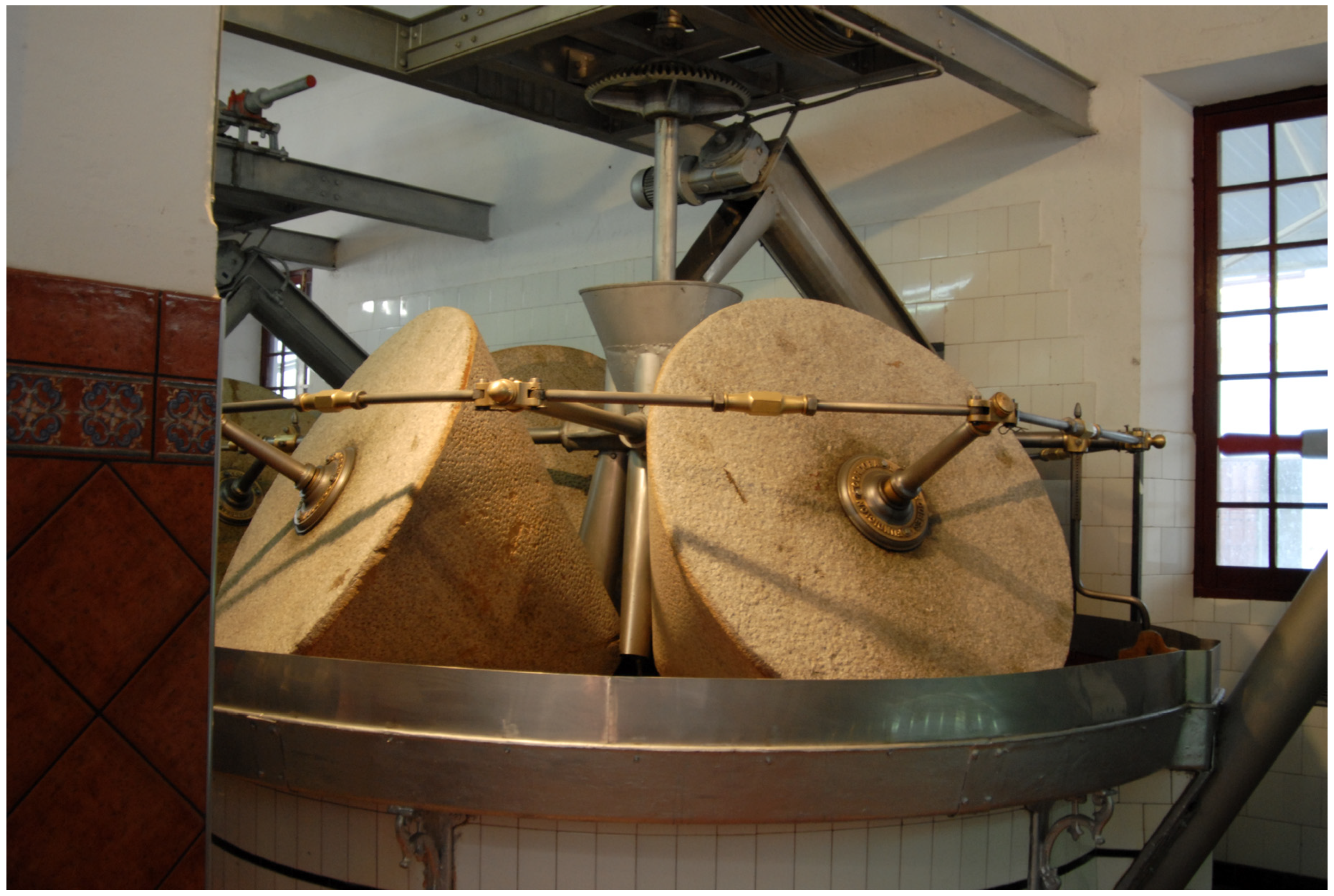
The starting material for this research was an olive oil mill composed of four conical granite stones located in the Núñez de Prado oil mill in the town of Baena (Córdoba, Spain) (Figure 1). This mill was the object of a study from the point of view of engineering graphics within a research project of the National Plan for Research, Development and Innovation of the Government of Spain, whereby the most notable classic presses and mills were analyzed using infographic techniques (for their enhancement in different olive oil museums in Spain), thus allowing a reliable 3D CAD model to be obtained.
The mill studied here is a complex system since it consists of four conical stones of 2112 kg, which would require a crane structure and an orderly assembly of all its elements. In addition, a perfect fit must be achieved using the adjustments and extenders of the rods of the grinding system, since it was vitally important that the millstones rotate without sliding on the hearth, which affects the quality of the oil obtained. In addition, the movement transmission system is quite simple and manages to take advantage when working at a low number of revolutions, since it was intended to place the friction between the stones and not the grinding speed. Similarly, from the structural point of view, the joints of the inertia flywheel structure present evident disadvantages that at first glance can lead to questioning the design of the mill due to the high number of elements present. The structure that allows the stones to rotate and move alone has 126 elements between rods, nuts, washers, or pins, among others.
Regarding the methodology used to obtain a 3D CAD model, Autodesk Inventor Professional software (release 2019, Autodesk, Inc., San Rafael, CA, USA). [25], a computer-aided design parametric software developed by Autodesk was used to obtain an accurate and reliable digital restitution of the mill.
Finally, from this 3D model, it was possible to carry out the CAE simulation using the finite-element analysis (FEA) method to perform a static analysis of the mill as a whole.
2.1. Operation of the Conical Stones Olive Oil Mill
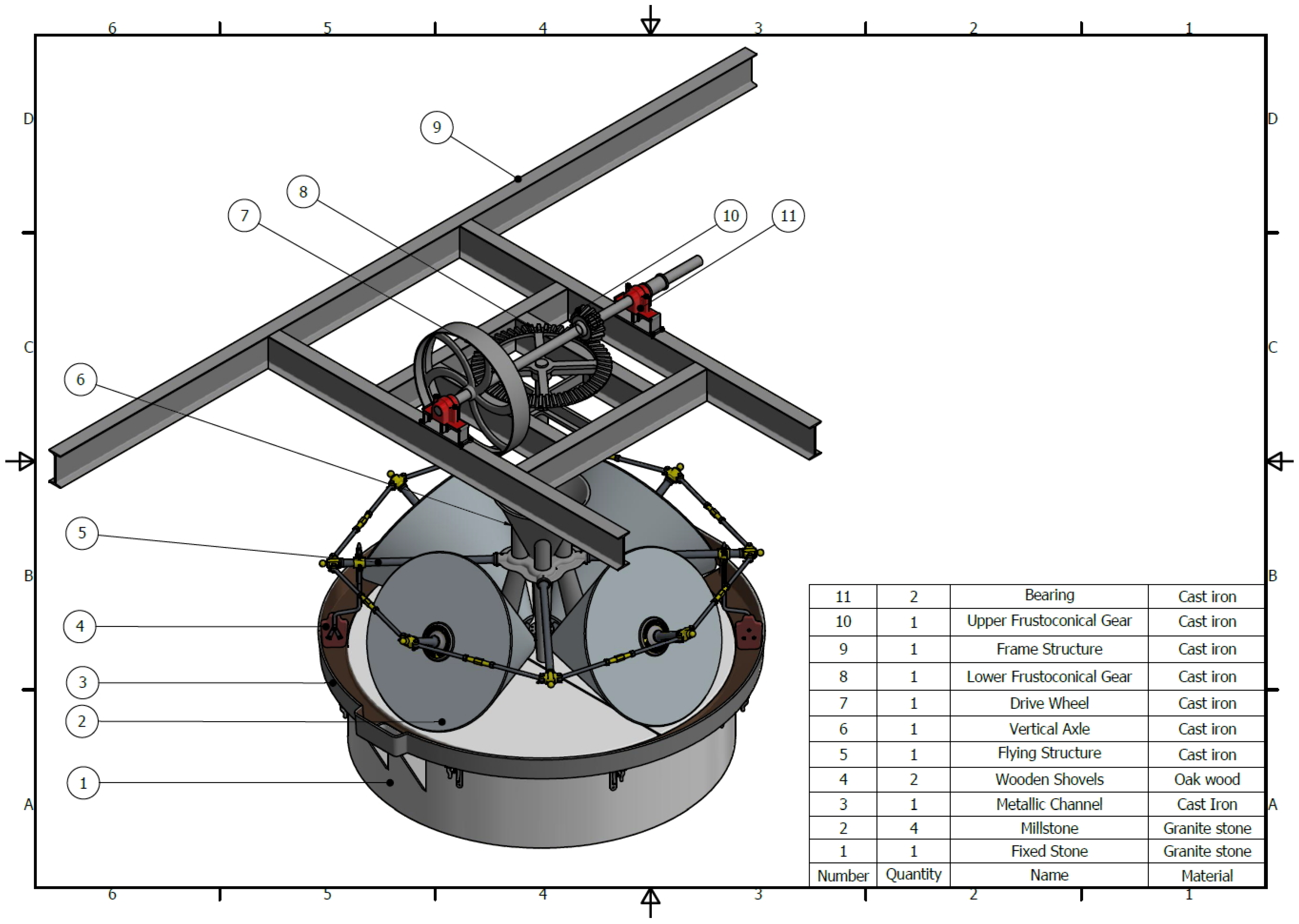
The first step in conducting a satisfactory complete study is to understand how the mill works. To describe the grinding system, the plan of the ensemble was followed through the marks of its elements (Figure 2).
The principle of operation of the conical stones olive oil mill is common to all grinding systems. It involves moving a large stone (called “volandera”) over another fixed stone or hearth (called “solera”), placing the element to be ground between them, in this case the olive.
The base of the conical stone olive oil mill is a large floor (fixed stone or heart) (1), specifically 3.15 m in diameter. On the hearth, four conical stones (2) rotate on their axle and move with respect to the vertical axle, pressing the olive arranged on that fixed stone. Moreover, on the hearth there is a metallic channel (called “alfarje”) (3) whose mission is to collect the oily paste obtained in the grinding.
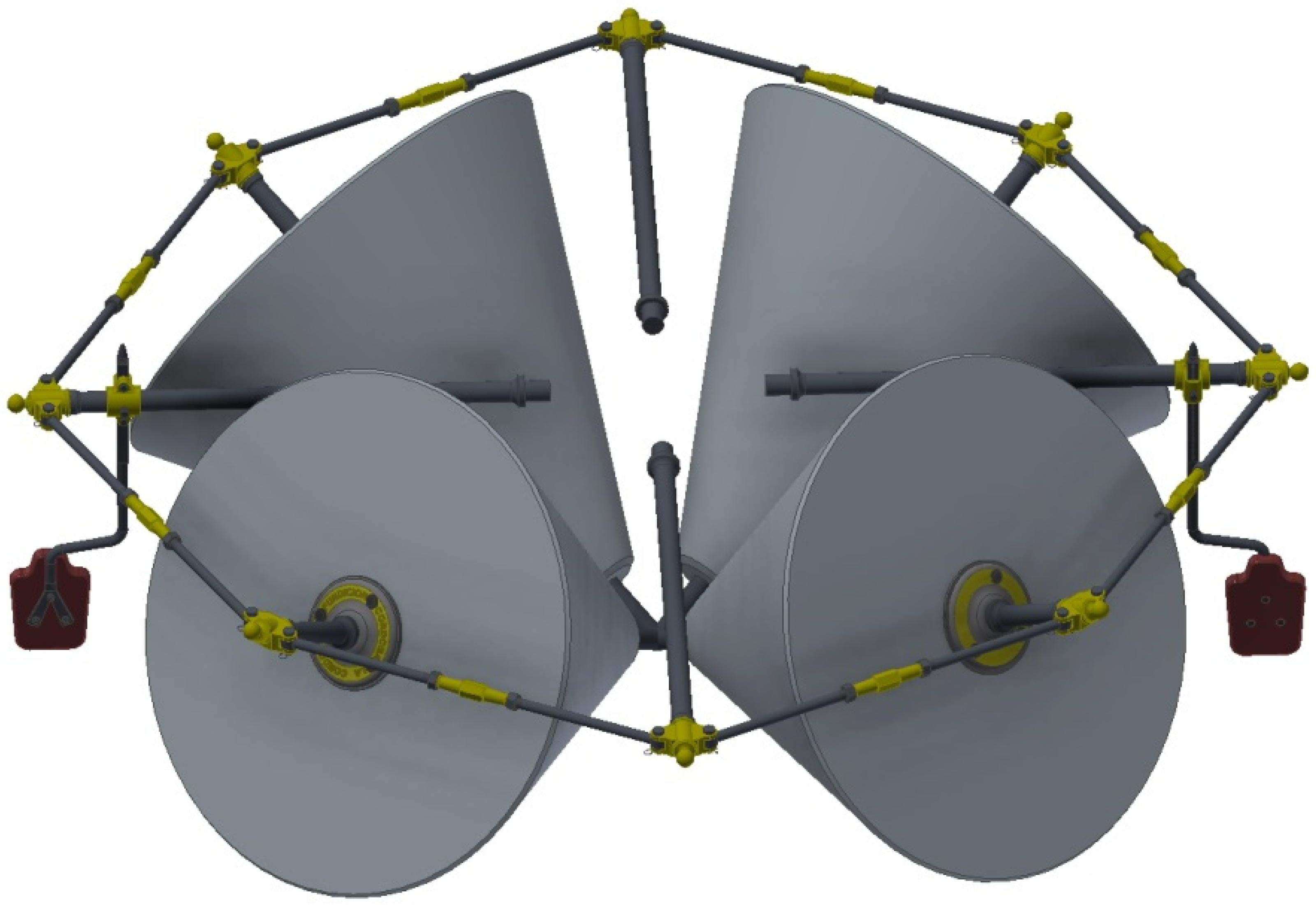
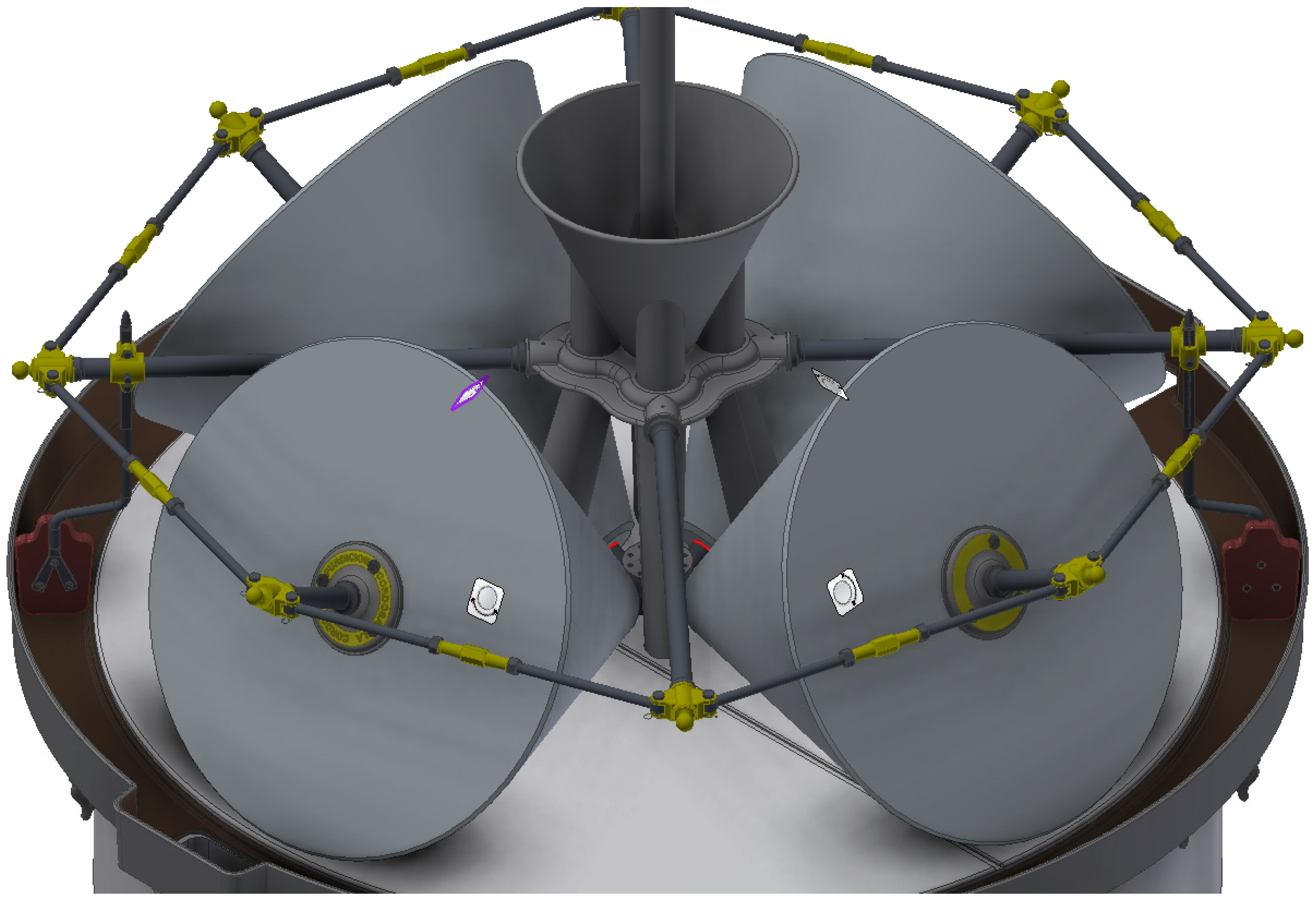
Each conical stone made of granite has a diameter greater than 1.45 m, a diameter less than 0.20 m, and a metal axle 0.725 m long. Thus, in order for each of them to move, it has a metallic axle that crosses it longitudinally and that at the outer end is connected by a flying structure (5) to the other three axes of the other three parts. This flying structure is connected by four horizontal axes to the vertical axle of the mill (6). Figure 3 shows the grinding system in the mill.
As is well known, olive milling results in a combination of three products—on the one hand, olive oil is obtained; on the other hand, “alpechin” or vegetation water is obtained from the olive itself, and finally pomace is derived from the skin, the bone, and the remaining fleshy part of the olive. These three different parts form an oily paste that accumulates in a metallic channel due to their movement due to the effect of centrifugal force. Similarly, the flying structure (5) has some wooden shovels (4) (called “raederas”) attached to two of its horizontal axes, with which the collection movement of the oily paste is facilitated, thus avoiding accumulation of large amounts of this paste in that channel, which could make grinding difficult and decrease the quality of the olive oil. Furthermore, the channel has two holes through which the oily paste is collected.
The vertical axle of the mill (6) with the fruit (olive) feeding hopper has a certain shape in order to allow the olive to pass through its interior and settle in the center of the hearth. Therefore, the lower part of the vertical axle is a few centimeters from the hearth, allowing the olive to come out. The central part of the vertical axle is shaped like a hopper and the fruit is poured onto it, and the upper end is topped by a lower frustoconical gear (8) of 1.15 m in diameter and with 60 teeth. The complete vertical axle is 2.67 m high and is made of cast iron.
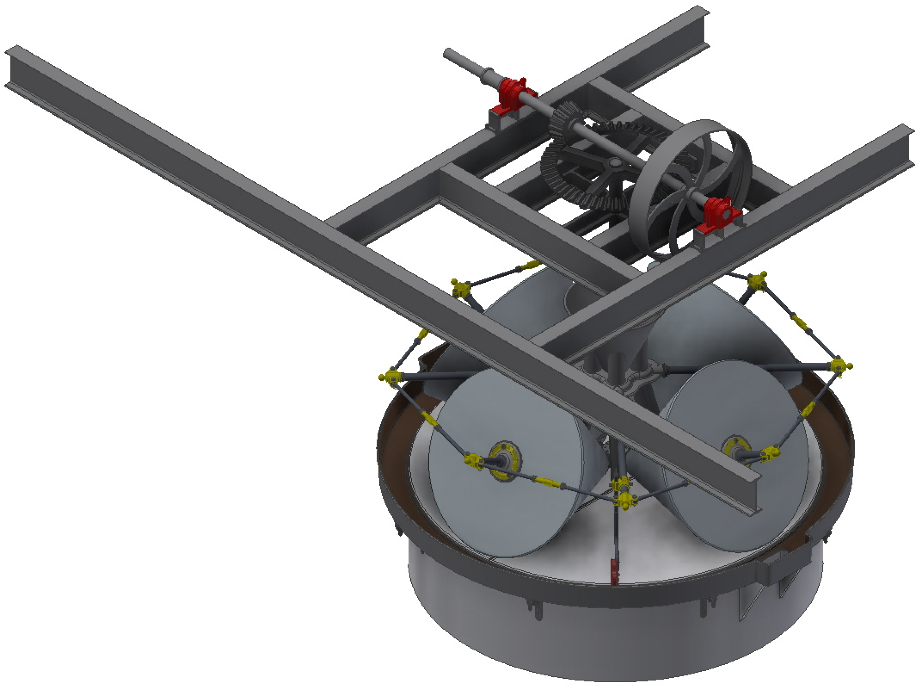
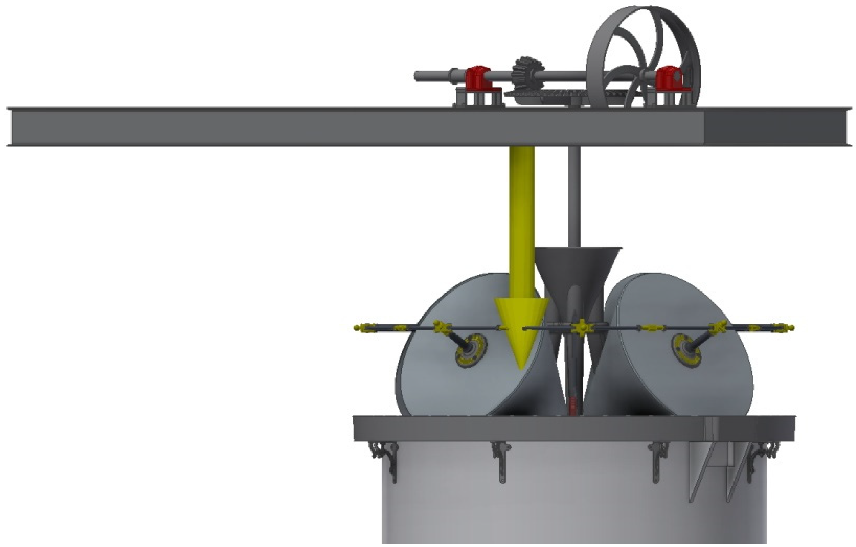
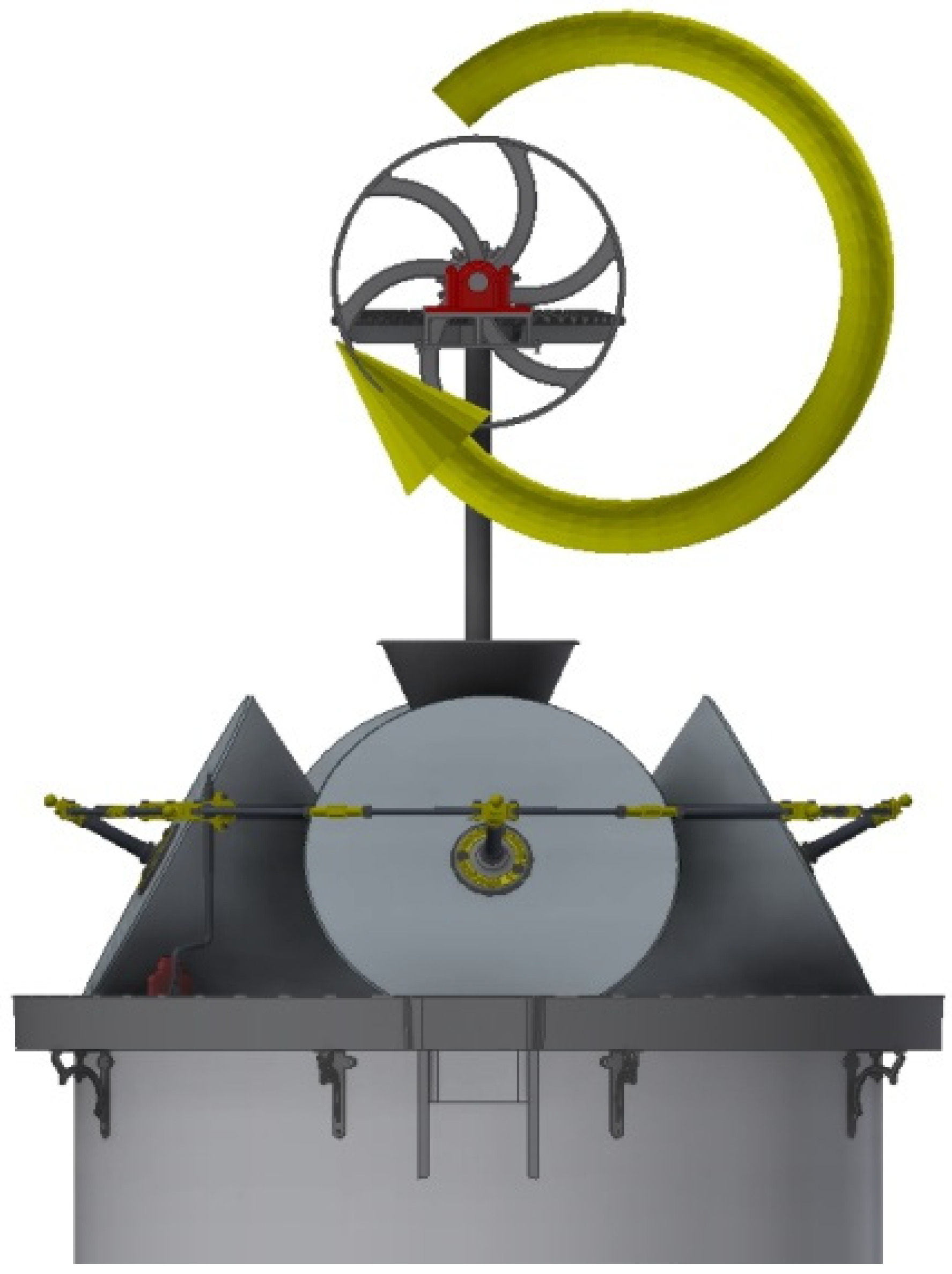
The vertical axle (6) is driven by the upper frustoconical gear (10) attached to a horizontal axle. This gear measures 270 mm in major diameter, 215 mm in minor diameter, 116.5 mm in height, and features 14 teeth. Therefore, the gear ratio between the gears is 7/30. Furthermore, the vertical axle at the end opposite to the upper frustoconical gear has a driving wheel (7) driven by an electric motor through a belt. This driving wheel measures 1.14 m in diameter and like the gear is jointly connected to a horizontal axle. Figure 4 shows an image of the motion transmission system.
Finally, a frame structure (9) supports both the horizontal axle and the vertical axle of the mill (Figure 5). The horizontal axle is supported on the frame by two bearings (11) that allow its rotary movement, while the vertical axle is suspended from the frame itself by a through hole that works as a collar. The vertical axle only supports its own weight as the stones are directly supported on the hearth, and therefore it does not need a bearing to facilitate its rotation.
2.2. Computer-Aided Engineering (CAE)
Once the CAD model has been obtained and the operation of the mill has been understood, the static analysis of the mill will be carried out using FEA thanks to the stress analysis module contained in the Autodesk Inventor Professional software. The stages that have been followed are as follows.
2.2.1. Pre-Processing
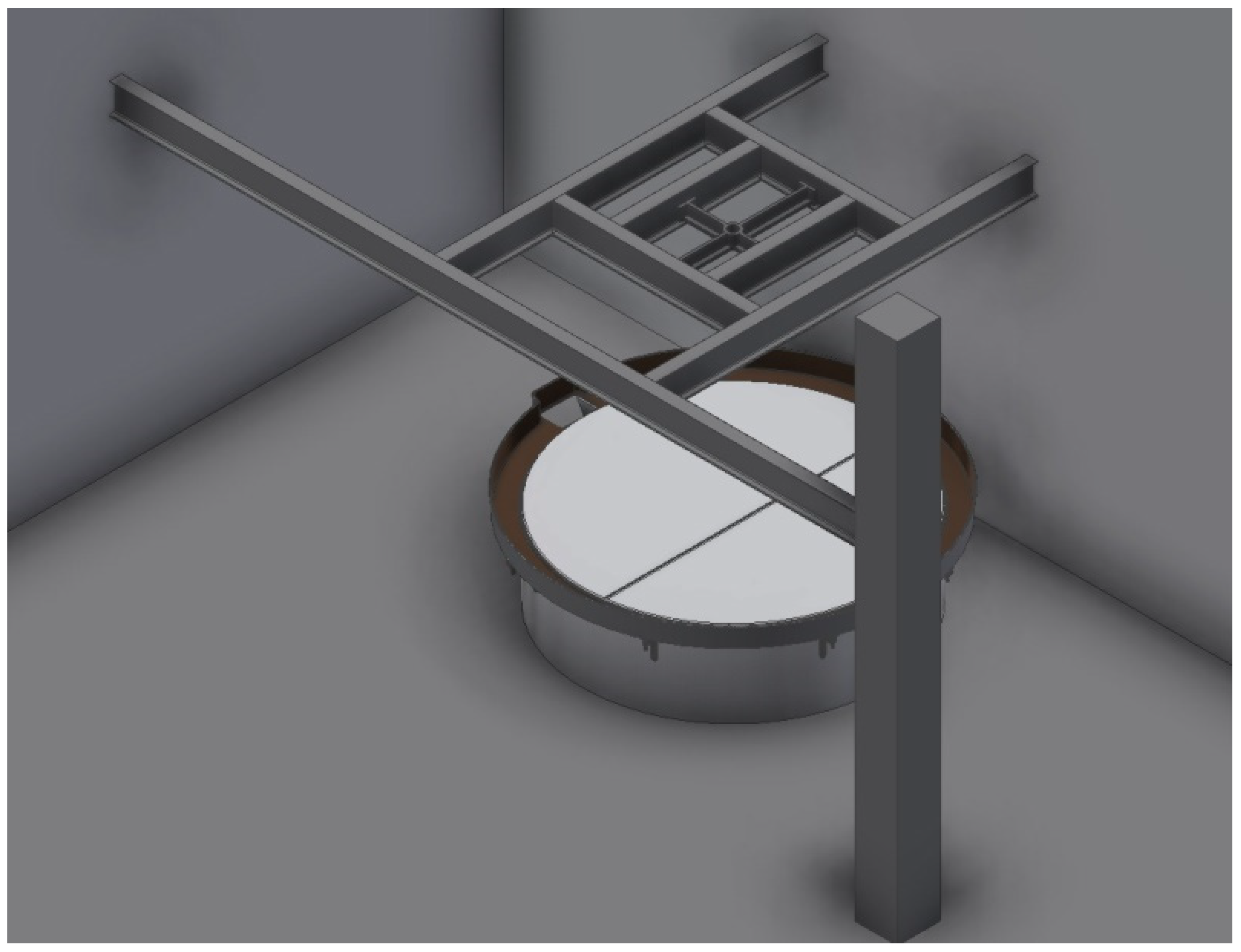
The preprocessing is nothing more than the simplification of the model in order to facilitate its static analysis by requiring fewer computational resources. When performing the static analysis, the first thing to establish are the components and elements of the environment that are not part of the system, in order to avoid distorting the analysis. On the other hand, it is also essential to correctly define its working position, since the device must have a static behavior—a static analysis of something that behaves dynamically cannot be performed. For this reason, the static situation of the assembly must be conveniently defined.
In standstill conditions, the conical stones olive oil mill can be studied as a static set of elements that are only affected by gravitational force, but there is a case in which the mill is subjected to a greater stress that causes greater stresses in the whole set—a blockage of one of the stones. The static analysis to be carried out on the mill occurs in the situation of shutdown due to blockage, and therefore from all the positions that the assembly can adopt, we will choose precisely the one that reflects this situation.
Figure 6 shows the simplified model of the set to be used in the static analysis, showing that the walls of the room where it was located and the floor have been removed.
2.2.2. Assignment of Materials
The material with which it is manufactured is assigned to each element of the 3D model thanks to the material library of the Autodesk Inventor Professional software, incorporating the physical and mechanical characteristics of each one, as the simulation cannot be performed if this allocation is not made.
On the other hand, it has been necessary to take the physical properties of the elements used from the Autodesk Inventor Professional material library because we do not know the specific properties of the elements used for their construction. There are studies that demonstrate the French origin of grinding stones, and it is well known that the cast iron used in the construction of the mill came from the “La Cordobesa” Foundry (which ceased to exist more than 40 years ago), but beyond these data it is not possible to obtain their specific physical properties without performing mechanical tests on items that are museum pieces. Therefore, the values offered by the Autodesk Inventor Professional material library were adopted.
For the present research, the materials used were polished granite for the millstone, cast iron for the metal, and oak wood for the wooden elements. Polished granite is considered an isotropic material with a Young’s modulus of 55,000 MPa, Poisson coefficient of 0.25, density of 2700 kg/m3, and an elastic limit of 39 MPa. On the other hand, cast iron has more resistant values; specifically, it is also an isotropic material, having a Young’s modulus of 120,500 MPa, Poisson coefficient of 0.30, density of 7150 kg/m3, and elastic limit of 758 MPa (only elastic material models were used and the elastic limit was only pursued in order to determine the safety coefficient, as can be found in Section 3.2).
Finally, oak wood is an orthotropic material (with three different values of the Poisson coefficient and Young’s modulus depending on the direction), but with a constant density value of 760 kg/m3 and an elastic limit of 41 MPa in the direction parallel to the grain.
However, the introduction of an orthotropic material could jeopardize the static analysis of the model since it is not possible to carry out a classical study from von Mises stress. At any rate, the only elements made of wood are the wooden shovels or “raederas” that push the ground paste. This element also does not have a structural function, so if it is taken as an isotropic element taking the lower values of resistance, the static analysis of the assembly is not affected.
2.2.3. Boundary Conditions
The next stage in static analysis is the definition of boundary conditions. For its correct definition, it is essential to determine the typology of the supports of the model, arranging them precisely in each place, with this being the first step to undertake.
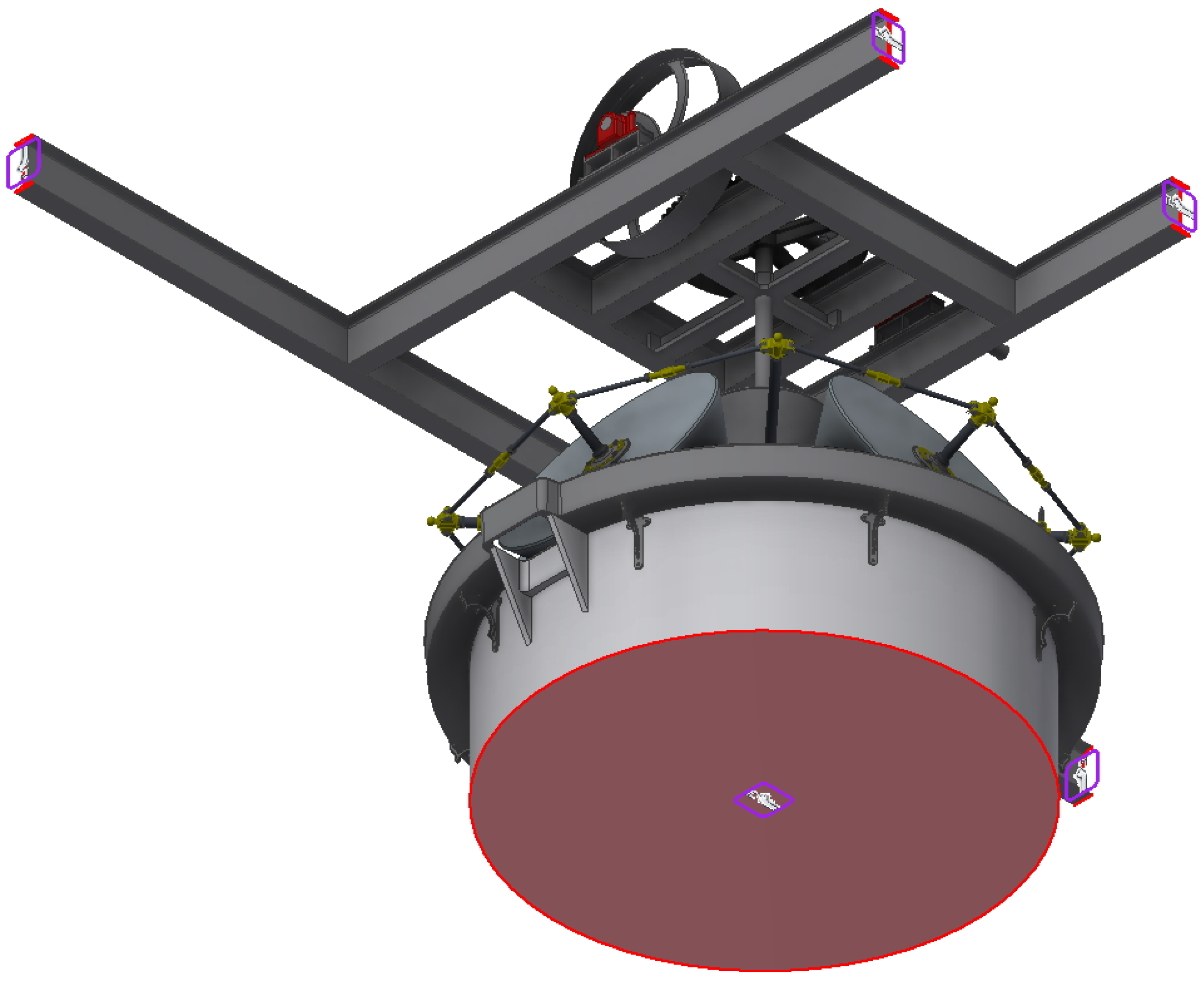
The supports are commonly classified into fixed, articulated, and mobile supports. Autodesk Inventor Professional does not directly determine supports, but instead sets constraints for certain surfaces. Therefore, the fixed supports are configured by completely restricting mobility with respect to a specific surface. In the model, the ends of the beams and the lower part of the hearth present such a restriction (Figure 7).
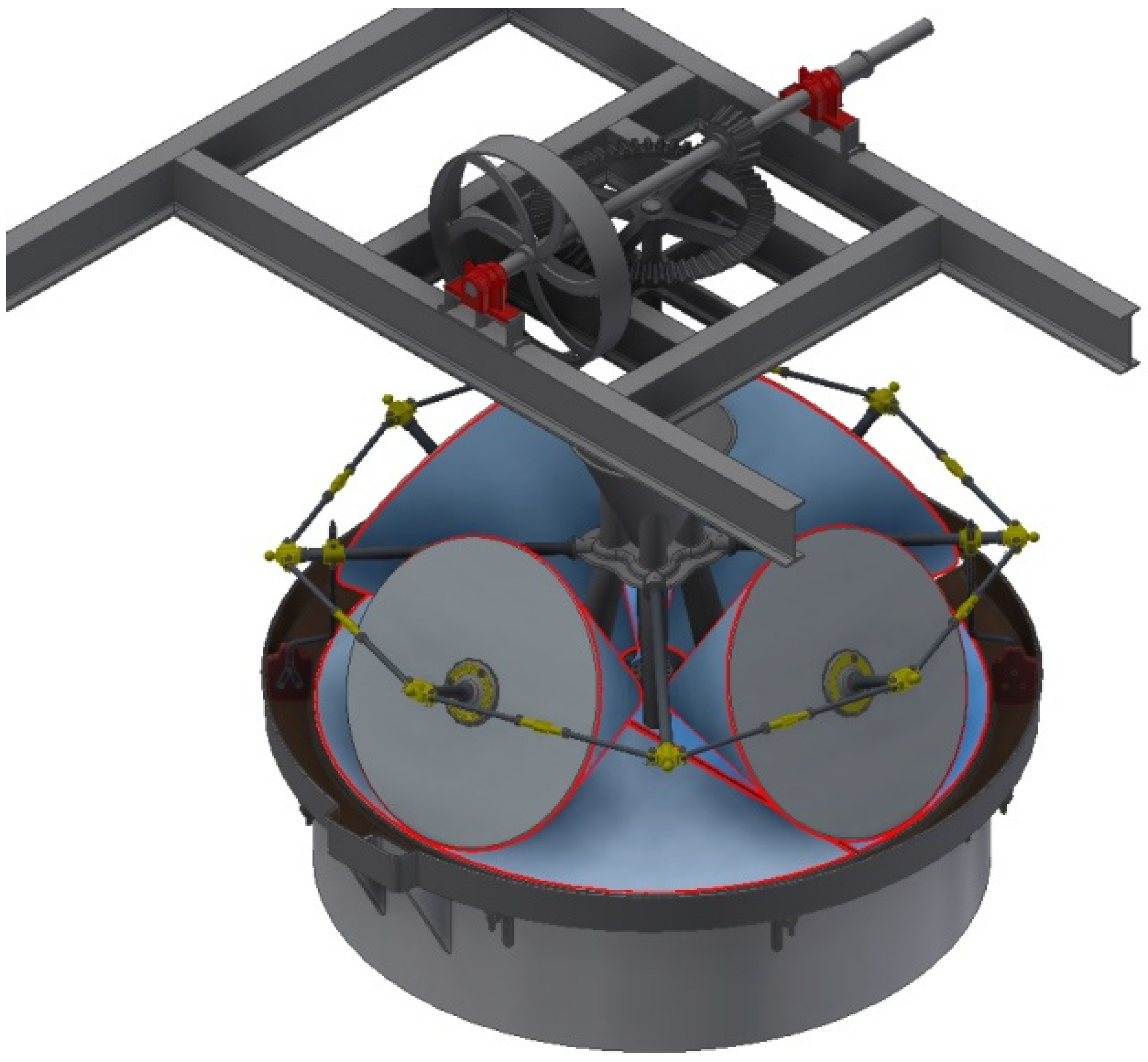
On the other hand, in order to establish the stoppage situation caused by blocking one of the stones, the surface of this stone must also present a complete restriction of movement (Figure 8). This situation would occur when a large obstacle that the stone was not able to overcome fell in the moving mill.
There are also surfaces that have a limited degree of restriction of freedom and can therefore rotate and move in the direction of the axle. These surfaces are the supports of the horizontal axle in its bearings (Figure 9) and the supports of the axes of each of the stones (Figure 10).
Once the restrictions on the supports have been defined, the program automatically generates the contacts between the different elements. If the assembly is well modeled, with the constraints and the relationships between the different elements being established during the assembly, it is not necessary to add more contacts to the model. However, it is always advisable to check the contacts in areas with complex geometry, as is the case in the present model with the contact between the gears. Autodesk Inventor Professional offers the possibility to generate the gears in the CAD model, defining their relationship and tolerances so that the contacts are correctly established in this study. However, there are some surfaces whose contact could not be easily defined, being those that exist between the lateral surface of the millstones and the hearth. The movement from one to the other is not that of a perfect geometric figure, since the ideal vertex of the straight cone of the millstone should be in the center of the circular surface of the hearth; however, the reality is more complex.
Depending on the amount of olives milled, the space between the millstone and hearth is different, and apart from that, the rotary movement may experience some drag. In any case, for the present study, it was necessary to manually define the contact between the millstone surface and the hearth, so that it is assumed that both will be in contact when turning. The weight of the millstone will therefore rest on the hearth, and the axes will really serve only to facilitate rotational movement. These contacts were defined manually (Figure 11).
2.2.4. Forces Applied
Once the definition of the boundary conditions was finished, it was time to define the actions that affect the model. There are fundamentally two forces to apply: first, the gravitational force that affects the entire assembly, and secondly, the torque applied to the inertia flywheel that drives the transmission system.
The gravitational force represented on the center of gravity of the entire model (Figure 12) is that derived from the acceleration of gravity, defined by taking the z-axis of the model (in the negative direction) and an intensity of 9.81 m/s2.
The torque, on the other hand, is applied to the inertia flywheel of the horizontal axle and is produced by the belt drive with a 3500 W electric motor. In addition, it is known that the stones take a complete turn during the milling process in 27.5 s and that the relationship between gears previously exposed is 7/30; thus, the upper axle rotates at a rate of 9.375 rpm, equivalent to 0.98 rad/s.
Work can be expressed as an integral of power (P) by the time differential (dt) or as an integral of force (F) by the displacement differential (dx):
If both equations are equalized, we obtain
where ν is the linear velocity in m/s.
For the circular movement: , with being ω the angular speed in rad/s and r the radius in m, so by substituting
and by freeing F, we have the force applied at the end of the inertia flywheel:
Finally, the torque applied to an inertia flywheel (M) is
Since the angular speed of the inertia flywheel is approximately 1 rad/s, then the torque applied to the inertia flywheel will be 3.5∙106 N.mm. It is actually based on a hypothesis that is not entirely true, since part of the energy generated in the electric motor is lost in friction and resistance. However, if these data are taken as the maximum achievable torque when analyzing the model, it will be in a situation of von Mises stresses on the safety side (Figure 13).
2.2.5. Meshing
The last step prior to simulating the von Mises stress analysis is obtaining the meshing or discretization of the 3D model. To carry out an FEA of a model, it is necessary to have a mesh of simple elements that characterize its geometry. The vertices of that mesh, called nodes, serve as a link between several simple elements, and the relationships between the values of the neighboring nodes can be written as a system of linear equations. However, the greater the number of nodes, the greater the computational requirements necessary to solve all the equations and determine a result.
Autodesk Inventor Professional automatically generates a tetrahedron mesh that appropriately characterizes the model geometry. Undoubtedly, this automatic mesh has its limitations, and other specialized software start from other types of elements of a different order in order to discretize the model; however, the tetrahedral mesh yields perfectly acceptable results for the level of study that is intended.
Meshing limitations also have to do with the geometry of the model. If its geometry is complex, the mesh adapts poorly to those regions. To avoid this problem, the software allows the mesh to be reworked manually (mesh refinement), determining the maximum distance between nodes in some regions or in those where the stresses are concentrated, as the results are more reliable if the mesh is better adjusted to the geometry.
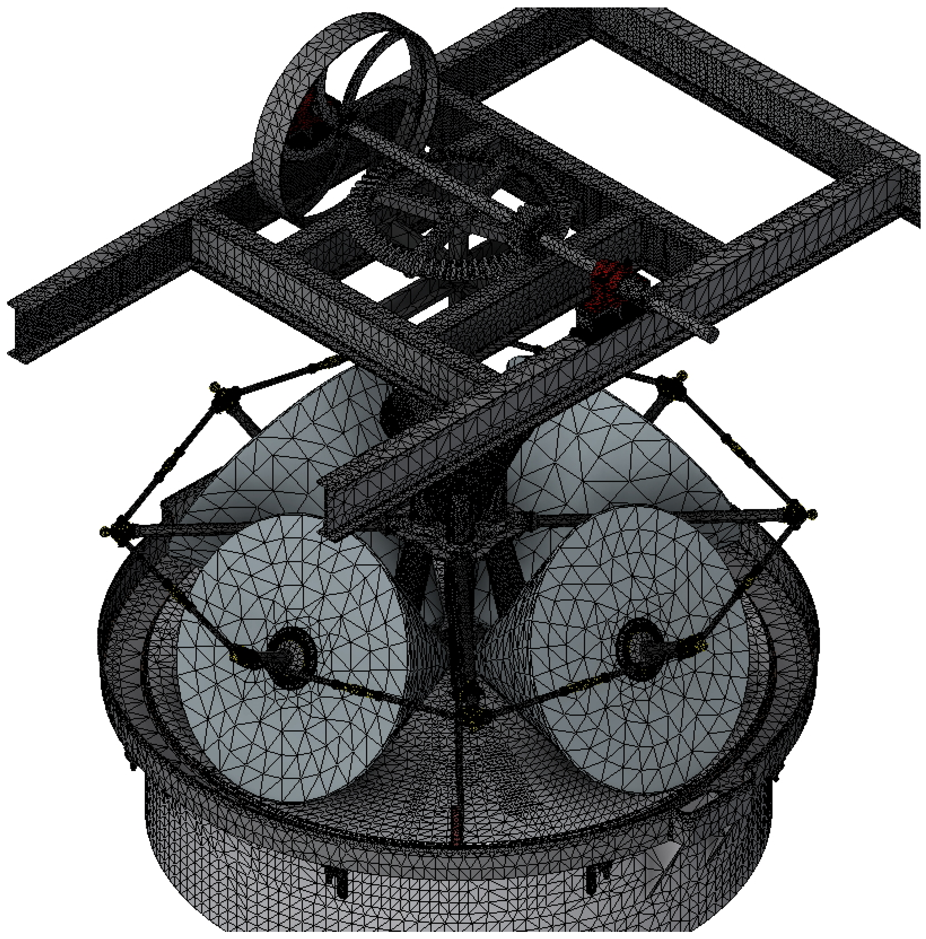
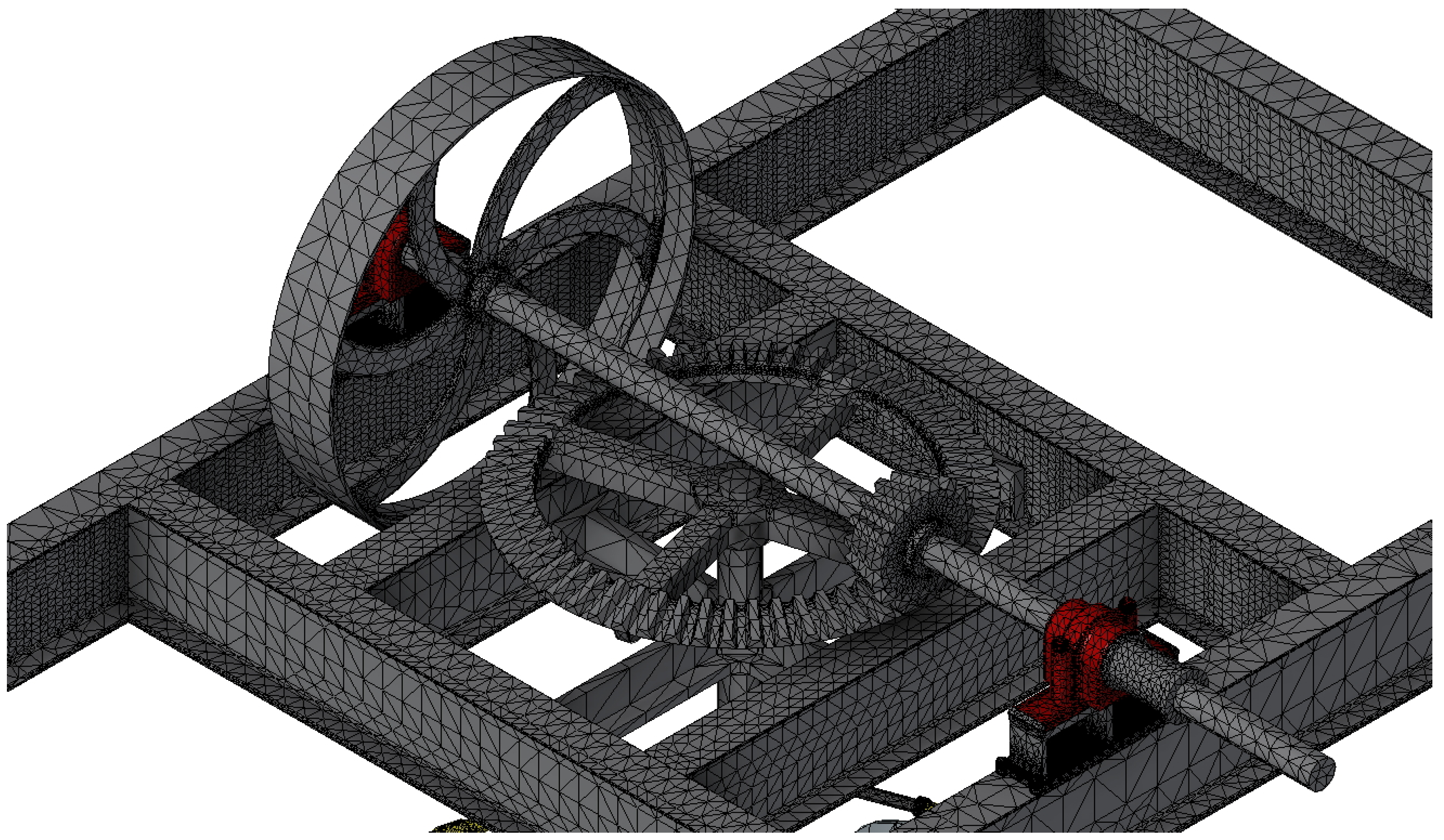
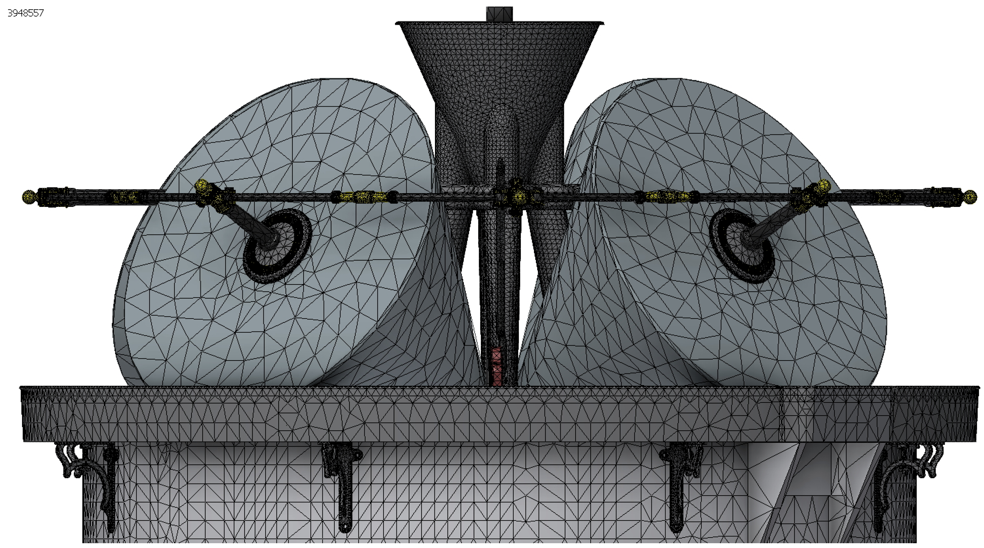
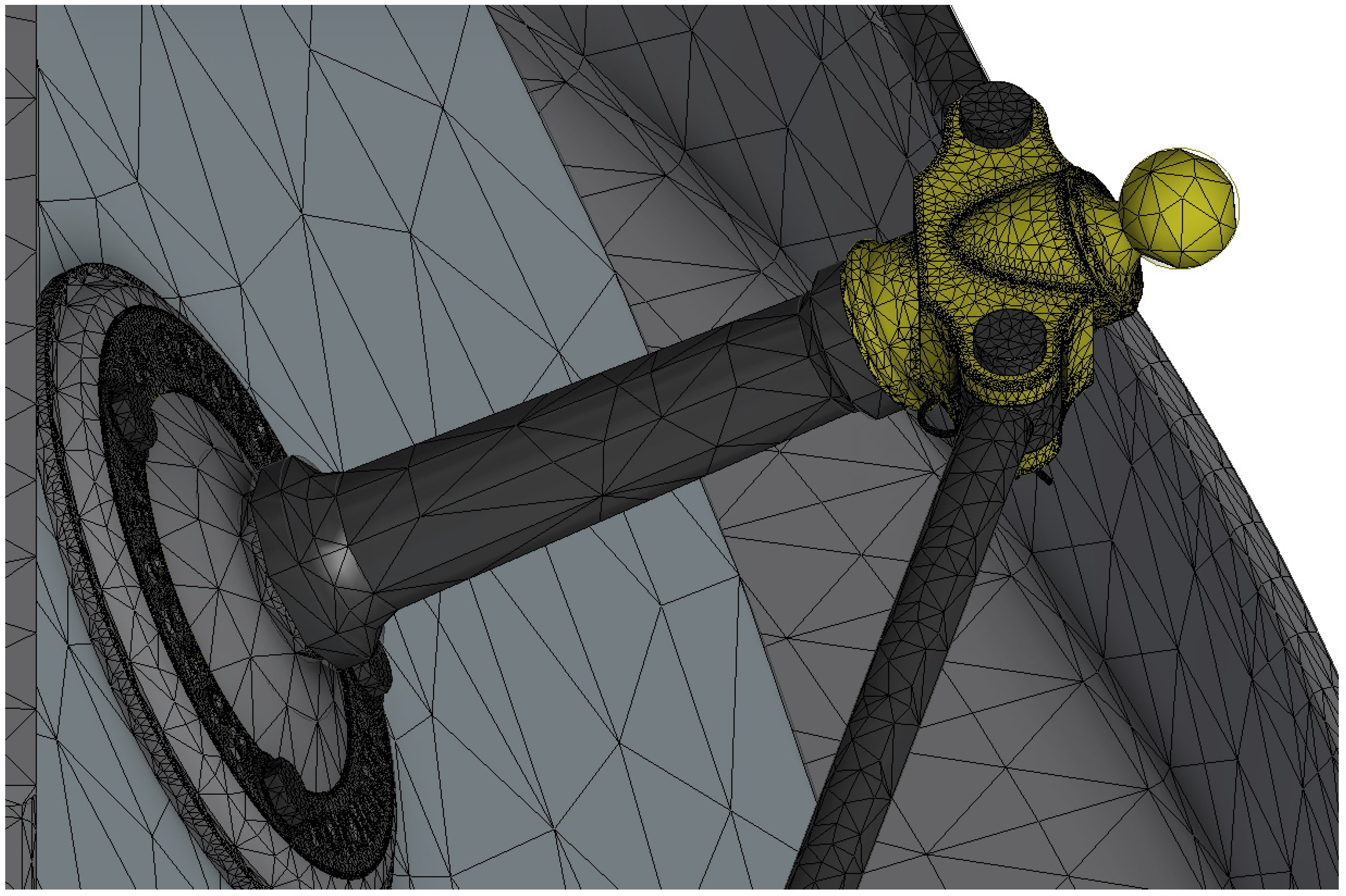
In this study, a tetrahedral mesh was obtained from the default values offered by the software. The average size of the mesh element was 0.1 times the size of the bounding square, its minimum size was 0.2 times that of the average element, and the variability factor between contiguous elements was 1.5. Finally, the maximum angle of rotation between tetrahedral surfaces was 60°. With these parameters, the result of the meshing obtained was precise, fitting correctly to the geometry (Figure 14, Figure 15, Figure 16 and Figure 17).
Taking into account computational resources, the analysis in this study used a mesh size of 2,411,959 elements and 4,090,008 nodes.
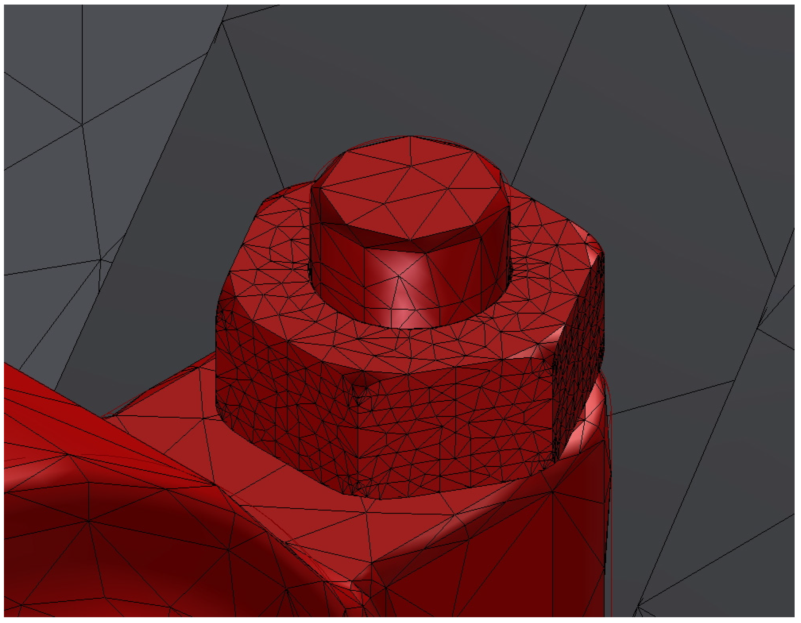
Finally, there are a series of elements that, due to their complex internal geometry and the concentration of stresses, will receive a modification in their mesh size, that is to say a refinement of it. Specifically, it concerns the bearing nuts. The sinus of the nuts is defined by a helical groove in contact with that of the screw, and therefore it is a complex geometry. On the other hand, the bearings receive high stress derived from the opposition to the movement of the system and the torque applied to an element in its proximity, the inertia flywheel. These two factors have been decisive in reducing the mesh size of the element to another whose maximum length is 3 mm (Figure 18).
3. Results and Discussion
After the preparation of the 3D model, once the previous stages were carried out, the FEA was performed in order to obtain results with an indication of the von Mises stresses, displacements, deformations, and the safety coefficient. However, before carrying out such an analysis, it is convenient to check beforehand, by means of a modal analysis, if the model behaves as a static set or if, on the contrary, it behaves as a mechanism. In the latter case, there would be no point in performing a static analysis.
In terms of the interpretation of the results, it is convenient to point out that von Mises stresses were used instead of principal stresses. Although these showed somewhat lower values than the principal stresses for the elements made of wood, it does not mean that these values were not valid, as they provided important indicative values, which, moreover, will not be too far from the value maximum stress in the most unfavorable direction.
3.1. Modal Analysis
Modal analysis is sometimes performed on the model, in the absence of loads, by means of a resonance study by which the mobile elements of the model are determined at frequencies. When the model does not behave statically because the whole or some of its elements can move freely, then the frequencies at which the displacements occur are low (less than 2 Hz).
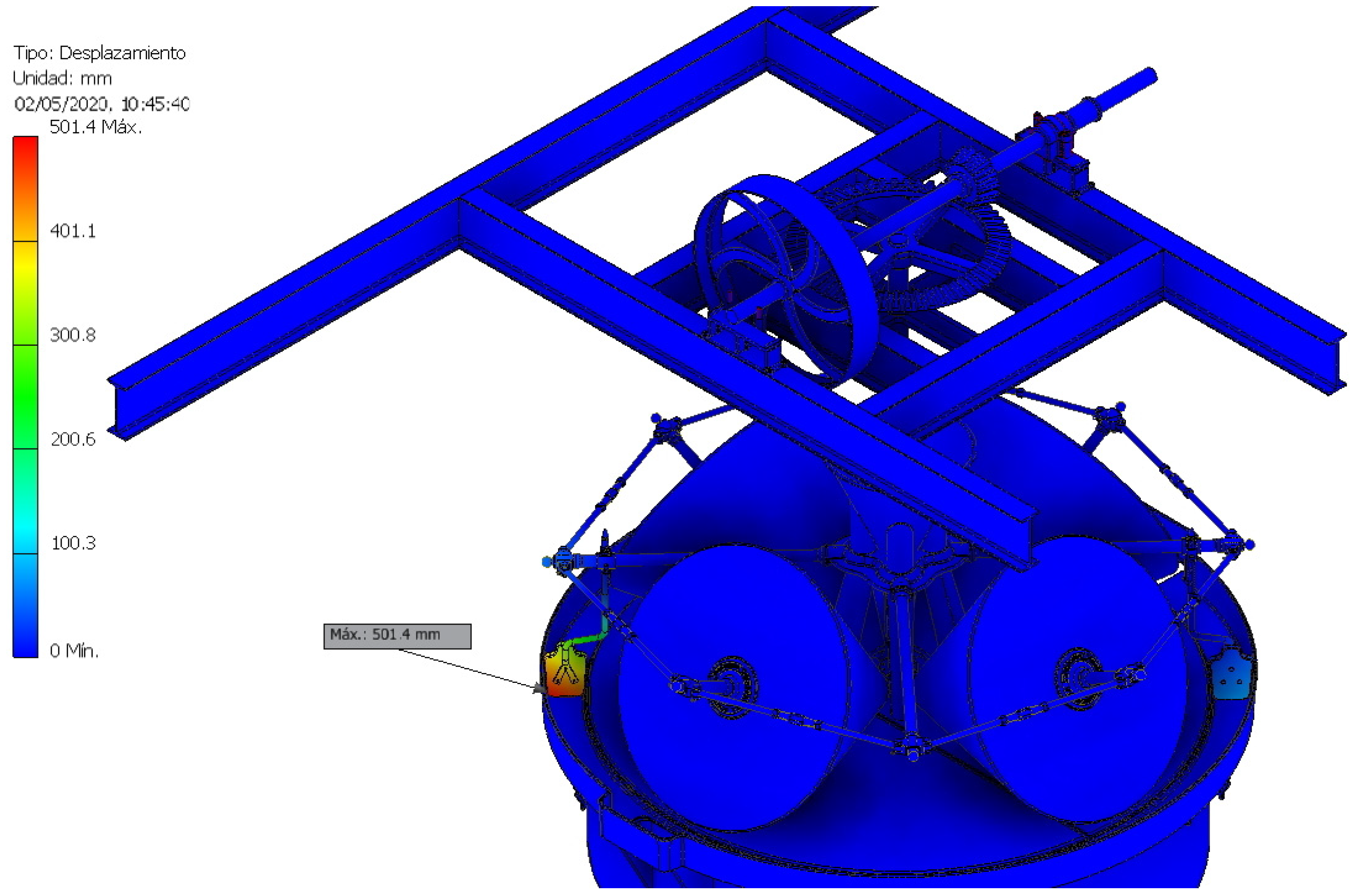
In the present study, the greatest displacement (501.4 mm) occurred at the lowest frequency at which the model had a large displacement, precisely at 10.99 Hz, which means that the model as a whole acts statically. The points of greatest displacement, as is logical, were the ends of the wooden shovels that were suspended in the air (Figure 19).
Autodesk Inventor Professional takes the eight lowest frequencies at which the model reacts by resonance. In this study, the eight modal frequencies obtained for the model were F1: 10.99 Hz, F2: 11.09 Hz, F3: 11.09 Hz, F4: 11.31 Hz, F5: 17.33 Hz, F6: 18.24 Hz, F7: 20.52 Hz, and F8: 21.41 Hz.
3.2. Static Analysis
In the FEA, the calculation of the value in each of the mesh nodes affects the nearby nodes, so it usually takes an iteration according to a given convergence criterion. Every time the software finishes calculating a value in each node it recalculates it, but starting from the final value calculated in the previous iteration. In general, if a stop criterion of 10% is established when the difference between the two values is less, the software stops iterating. In the present study, a maximum of eight iteration cycles and a stop criterion of 10% were established for the calculation of von Mises stress. Specifically, the software stopped in the fourth iteration with a convergence ratio of 6.229%, and thus the result was very consistent (Figure 20).
In the first iteration, the result of the analysis presented a maximum von Mises stress of 142.9 MPa and in the second, a value of 285.9 MPa, representing a huge increase of 100.1%. In the third iteration, starting from the value of the second iteration, a value of 263.9 MPa was obtained and, therefore, a variation of 7.69%. In the fourth and last iteration, the stress value obtained was 280.33 MPa, which supposed a variation of 6.229%. By obtaining a result that differs from the neighboring ones by less than 10%, the software takes this data as reliable and stops the calculation process. However, if a higher level of convergence were sought, the program could reach up to eight iterations, which would require greater computational resources, although the result obtained would not add much more precision to the analysis.
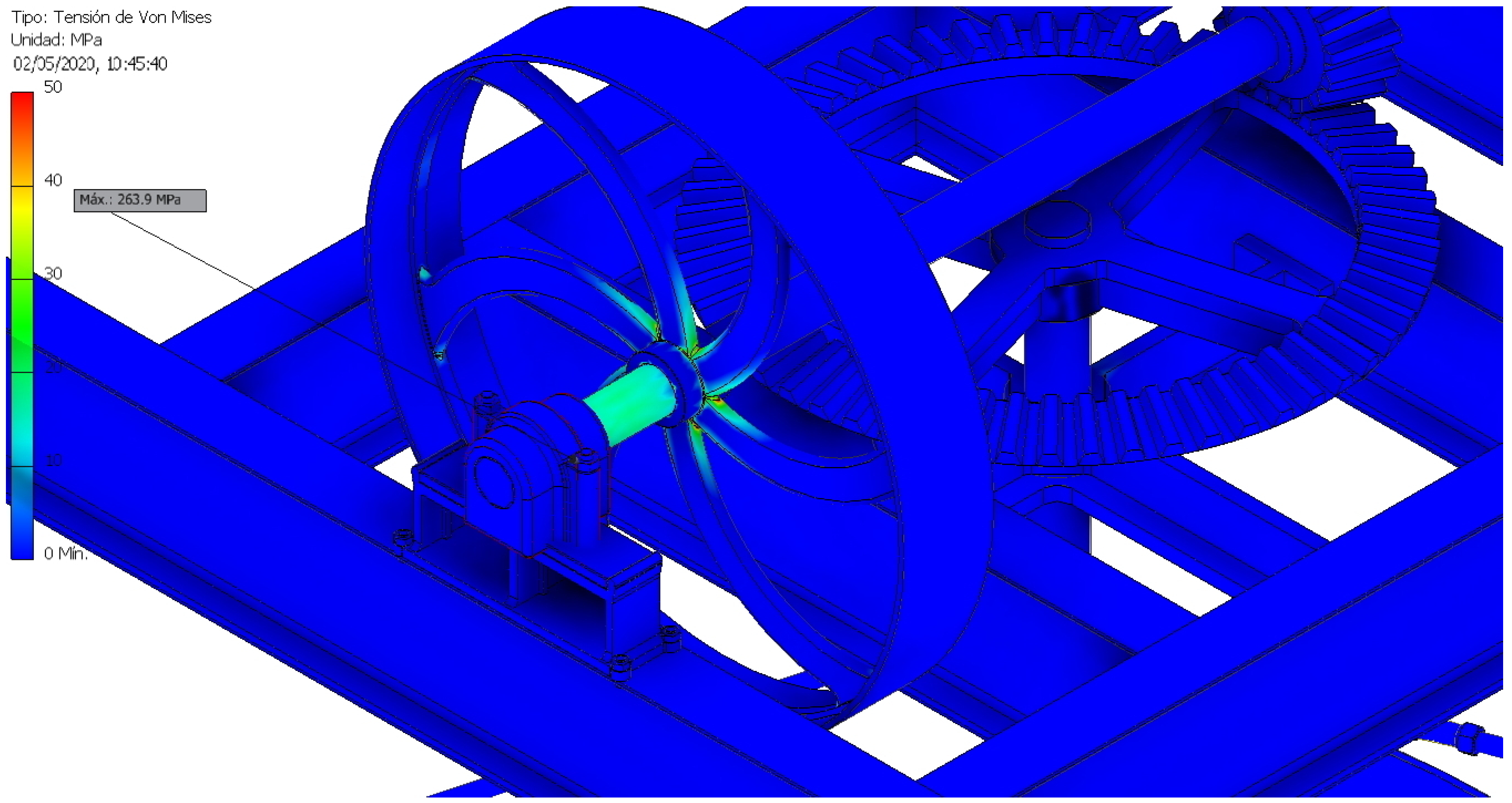
Figure 21 shows the von Mises stress distribution with the highest value indicated. In general, as can be seen from the color bar, the assembly is subjected to relatively low stresses for the materials it works with, far from the elastic limit of cast iron (758 MPa) for example.
Figure 22 shows the element with the maximum stress (263.9 MPa), which turned out to be the bearing nut where the horizontal axle rests. In addition, we can also appreciate how the stresses accumulated in the areas of the inertia flywheel radii close to the axle, although in this case they did not exceed 50 MPa.
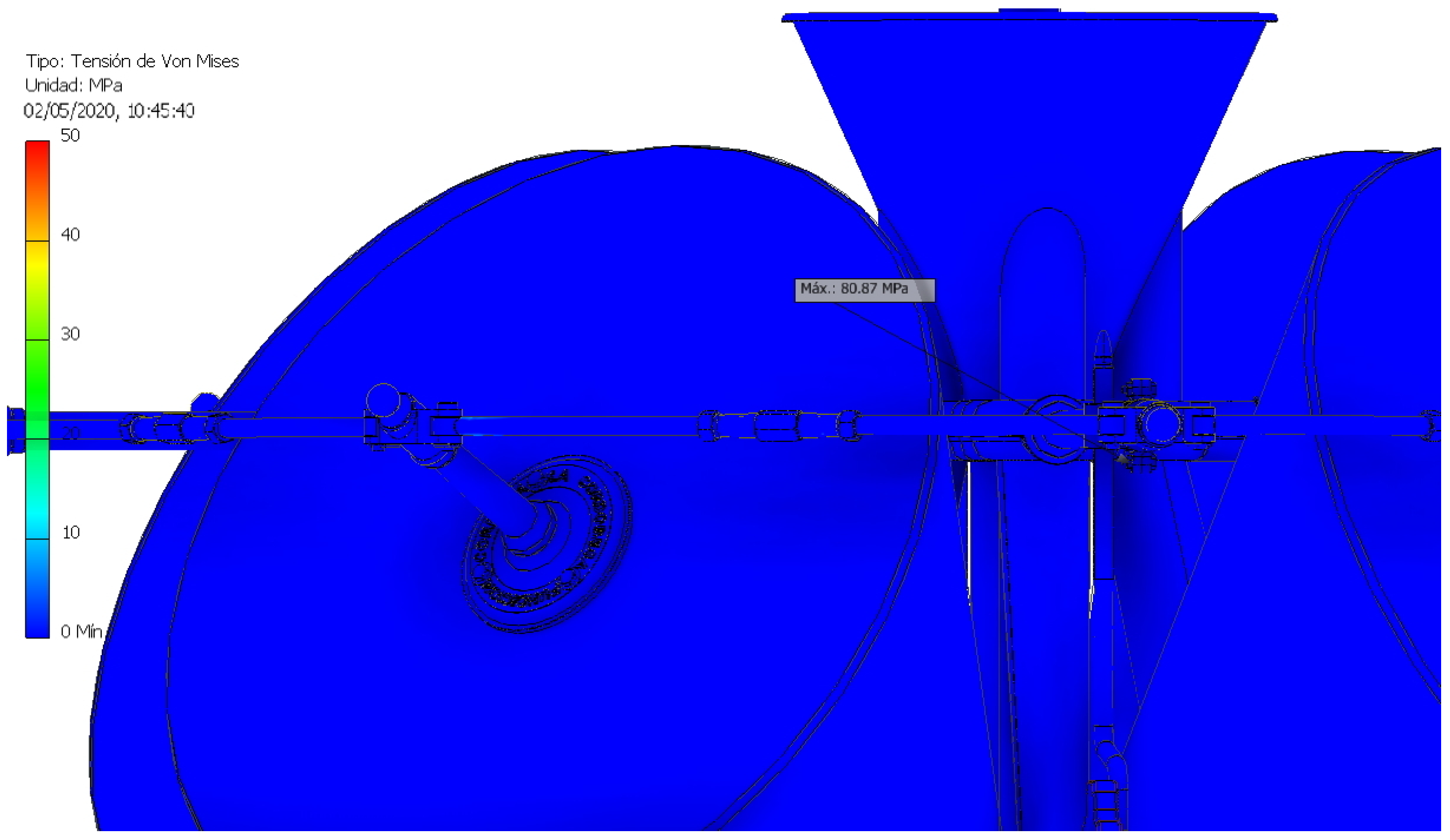
Apart from the bearing nut, the second highest von Mises stress was located on the bar that joins the vertical axle with the blocked millstone, reaching a value of 80.87 MPa (Figure 23). These results were predictable before carrying out the analysis, but it is striking that they were so far from the elastic limit of the material (758 MPa).
On the other hand, the safety coefficient results that were of greatest importance are presented. Safety coefficient (SC) can be calculated as the ratio of the maximum allowable stress to the equivalent von Mises stress (σvm), when using yield strength (YS):
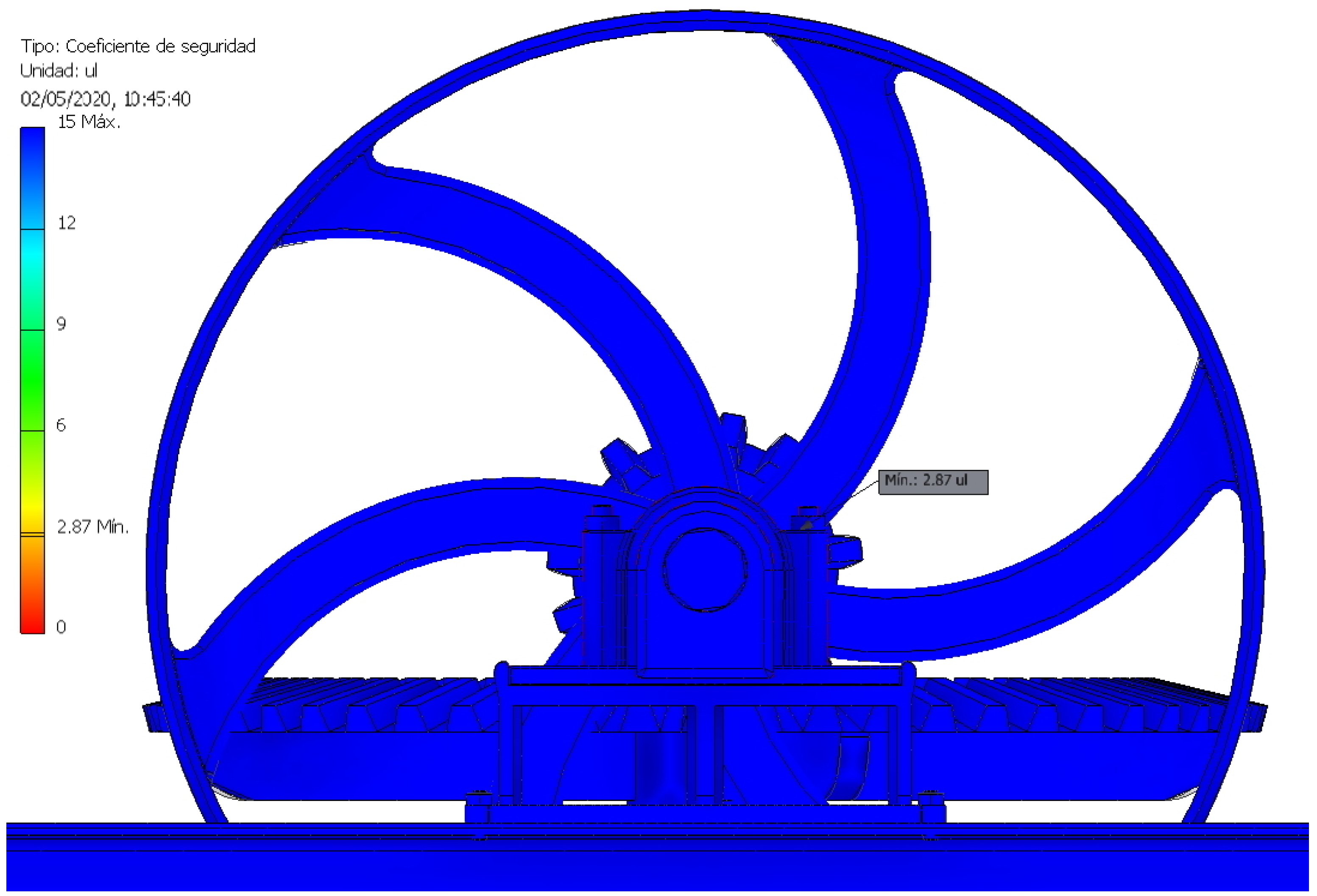
The higher the safety coefficient, the farther the element works from its elastic limit. Currently the study of materials is generalized and the materials are homogeneous, so it is convenient to work in ranges between 2 and 4, since presenting higher values would imply that the set is oversized. On the other hand, working in ranges of less than 2 is also dangerously close to the elastic limit and generates greater wear on the material. In the mill under study, the point with the lowest safety coefficient was the bearing nut with a value of 2.87 (Figure 24), which was still within the safety range; however, if the screw and the bearing nut of the inertia flywheel were redesigned, it would probably be able to work in a lower stress range.
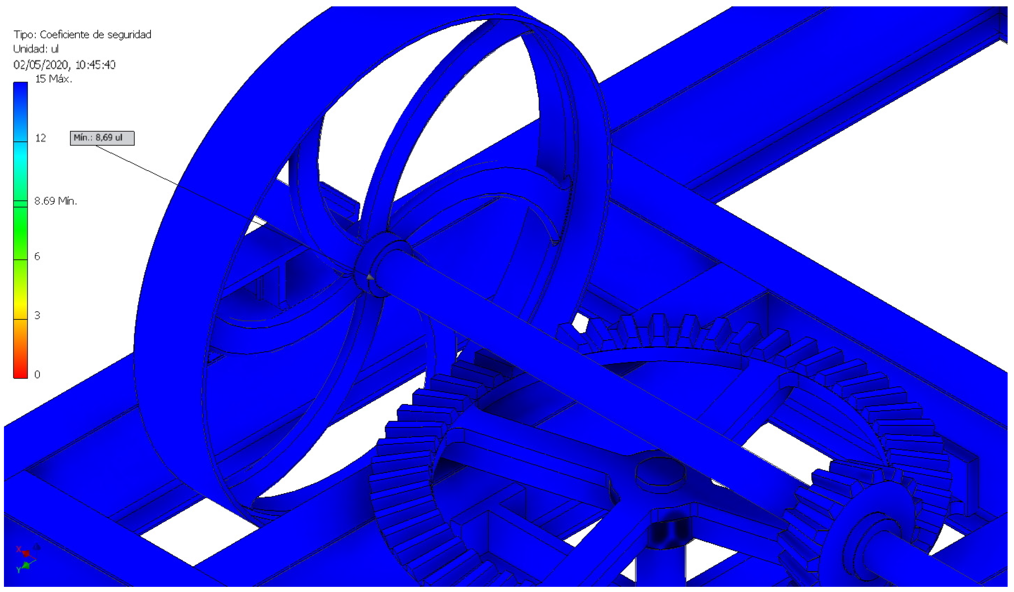
The second point with the lowest coefficient of safety was located at a point between the inertia flywheel and its horizontal axle with a value of 8.69 (Figure 25), indicating that it was very far from its elastic limit. This means that most of the mechanism was oversized and that it would have been possible to redesign a large number of its parts.
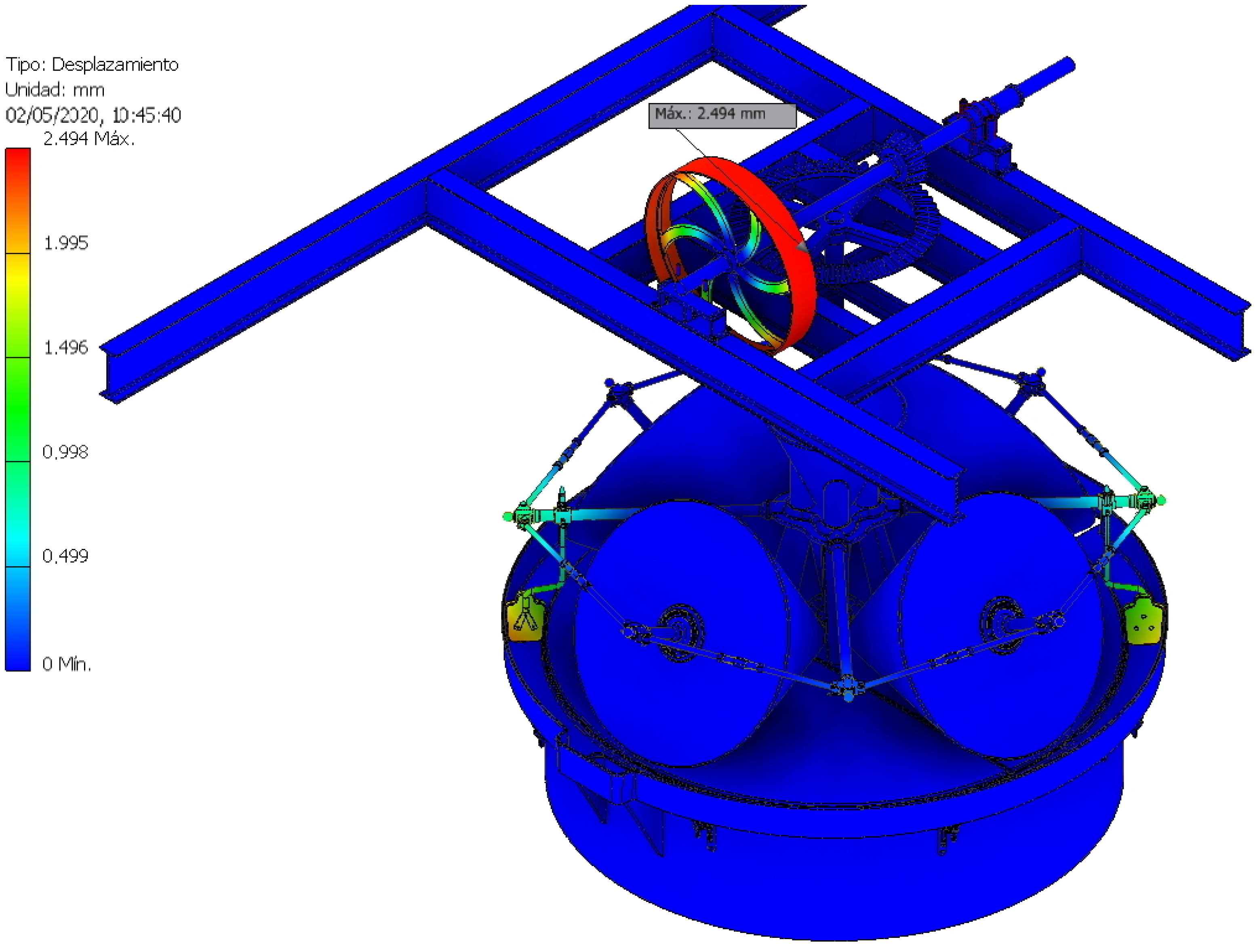
The study of displacements is another very important aspect because an element that suffers a large displacement, depending on its function, can prevent the assembly from working correctly. The model shows how these displacements are particularly delicate in the gears, although the maximum displacement took place in the inertia flywheel and did not reach 2.49 mm (Figure 26), and thus the displacements are negligible throughout the assembly.
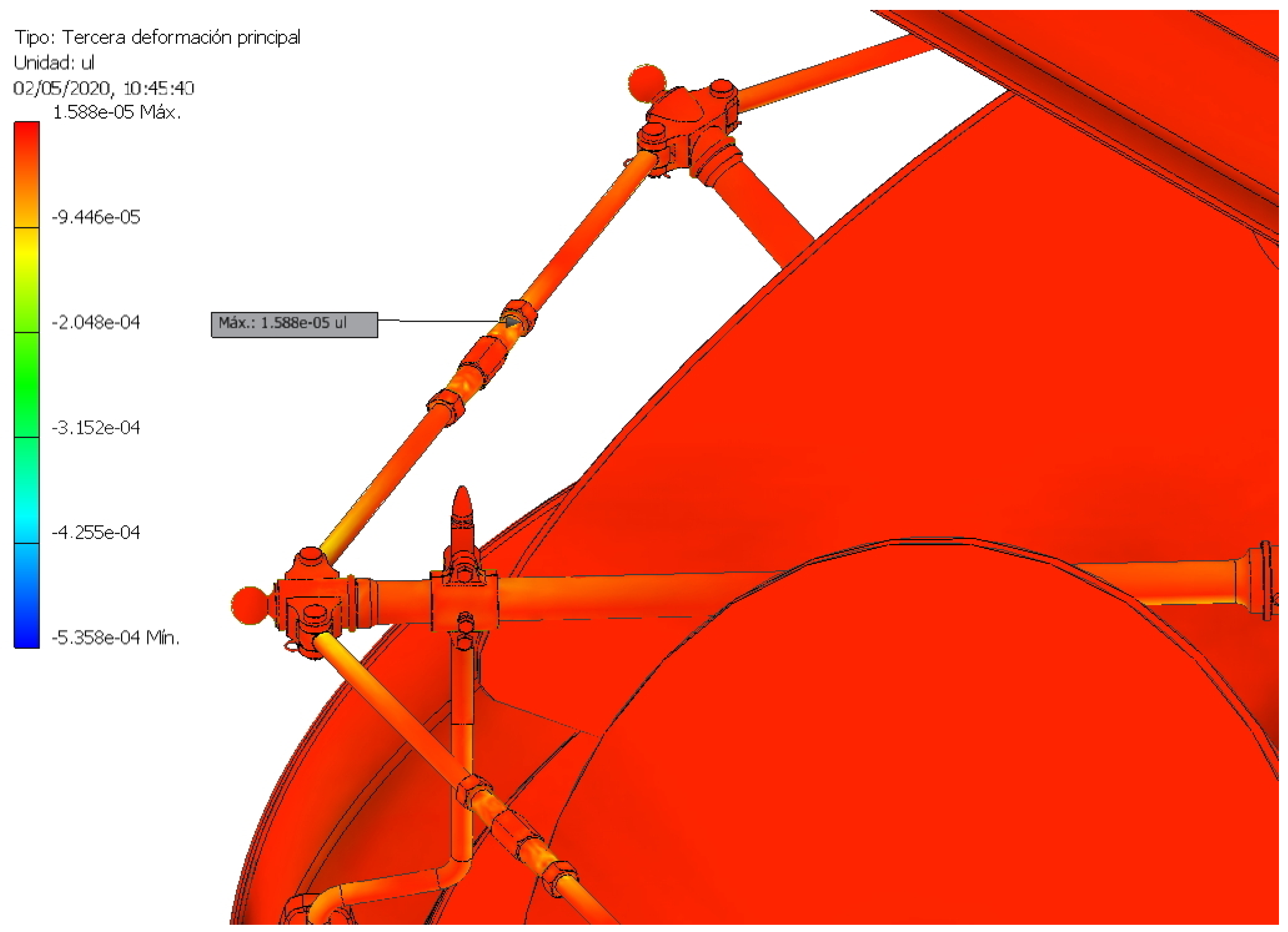
Finally, the equivalent deformation that is expressed as a percentage with respect to the length of the element was studied. In Figure 27, the maximum equivalent deformation can be observed as having a value of 0.06283% of its length, and in Figure 28, the third main deformation with a value of 0.0015% of its length is shown. Therefore, it can be said that the equivalent deformation suffered by the assembly is negligible.
4. Conclusions
The article shows the results of the static analysis carried out on the 3D model of a conical stones olive oil mill from the 20th century. In order to achieve this, we used CAE techniques, thanks to the parametric software Autodesk Inventor Professional.
Static analysis revealed that the conical stones olive oil mill was a very robust machine, although under working conditions, it can be said to have been excessively oversized. When studying the set in a situation of blocking one of its millstones, which would be the worst possible scenario, the machine was found to not break either. The element with the highest stress (bearing nut) would be subjected to a von Mises stress of 263.9 MPa, far from the elastic limit of cast iron with a value of 758 MPa.
Thus, the element with the lowest safety coefficient (2.87) was the same nut with the highest von Mises stress, although the next element with the second lowest value of said coefficient had a value of 8.69, which showed that the set was oversized. This conclusion shows the convenience of redesigning the set in order to resize some of its elements, as well as the fact that these could have lower safety coefficients (between 2 and 4).
On the other hand, the assembly hardly presented displacements or equivalent deformations that would jeopardize its operation. The maximum displacement obtained was 2.494 mm on the inertia flywheel itself, and the equivalent deformation did not reach 0.1% of the dimension of the element. Thus, these results also show that many of its elements could be redesigned by arranging a lesser amount of material, without the need to lighten the mass of the stone whose function is not structural but is intended to mill the olive. After a first analysis, the resizable elements would be fundamentally those that have to do with both the movement transmission system and its frame structure.
As future research, a dynamic analysis of the system could be carried out in order to observe the damage to the material that could derive from abrasion phenomena, mainly the contact between the millstones and the hearth.
Author Contributions
Formal analysis, E.D.l.M.-D.l.F.; investigation, J.I.R.-S.; methodology, J.I.R.-S. and E.D.l.M.-D.l.F.; supervision, J.I.R.-S.; validation, E.D.l.M.-D.l.F.; visualization, J.I.R.-S.; writing—original draft, J.I.R.-S. and E.D.l.M.-D.l.F.; writing—review and editing, J.I.R.-S. and E.D.l.M.-D.l.F. All authors have read and agreed to the published version of the manuscript.
Funding
This research received no external funding.
Acknowledgments
This research has been supported by the results of the Research Project of the National Plan for Research, Development and Innovation of the Government of Spain (reference HAR2009-06943). Moreover, we thank the oil mill Núñez de Prado for their kindness and collaboration in the aforementioned project by allowing visits to their facilities. Additionally, we sincerely appreciate the work of the reviewers of this article.
Conflicts of Interest
The authors declare no conflict of interest.
References
- Tempesta, T.; Vecchiato, D. Analysis of the factor that influence olive oil demand in the Veneto region (Italy). Agriculture 2019, 9, 154. [Google Scholar] [CrossRef] [Green Version]
- Lia, F.; Zammit-Mangion, M.; Farrugia, C. A first description of the phenolic profile of EVOOs from the Maltese Islands using SPE and HPLC: Pedo-climatic conditions modulate genetic factors. Agriculture 2019, 9, 107. [Google Scholar] [CrossRef] [Green Version]
- Castellano, S.; Di Palma, A.; Germinara, G.S.; Lippolis, M.; Starace, G.; Scarascia-Mugnozza, G. Experimental nets for a protection system against the vectors of Xylella fastidiosa Wells et al. Agriculture 2019, 9, 32. [Google Scholar] [CrossRef] [Green Version]
- Niavis, S.; Tamvakis, N.; Manos, B.; Vlontzos, G. Assessing and explaining the efficiency of extensive olive oil farmers: The case of Pelion peninsula in Greece. Agriculture 2018, 8, 25. [Google Scholar] [CrossRef] [Green Version]
- Cabanas, C.G.-L.; Ruano-Rosa, D.; Legarda, G.; Pizarro-Tobias, P.; Valverde-Corredor, A.; Triviño, J.C.; Roca, A.; Mercado-Blanco, J. Bacillales members from the olive rhizosphere are effective biological control agents against the defoliating pathotype of Verticillium dahliae. Agriculture 2018, 8, 90. [Google Scholar] [CrossRef] [Green Version]
- Zambon, I.; Serra, P.; Salvia, R.; Salvati, L. Fallow land, recession and socio-demographic local contexts: Recent dynamics in a Mediterranean urban fringe. Agriculture 2018, 8, 159. [Google Scholar] [CrossRef] [Green Version]
- Sordinas, A. Old olive oil mills and presses on island of Corfu, Greece: An essay on industrial archaeology and etnography of agricultural implements. Am. Anthropol. 1972, 74, 1519. [Google Scholar] [CrossRef]
- Rojas-Sola, J.I. A review of the historical procedures for obtaining the oil olive in the oil mills from the engineering graphics. In The Olive Grove and Its Oil; Fundación del Olivar: Jaén, Spain, 2013; pp. 67–96. (In Spanish) [Google Scholar]
- Montes-Tubío, F.; Burgos-Ladrón de Guevara, E.; Carranza-Cañadas, M.P. Geometric considerations about classic olive mills. In Proceedings of the International Conference on Engineering Graphics, Málaga, Spain, June 1998; University of Málaga: Málaga, Spain, 1998; Volume 1, pp. 157–165. (In Spanish). [Google Scholar]
- Lopez, M.Y.; Montes, F.; Burgos, E.; Moreno, A. Technological-functional and architectural analysis of the Cordovan oil mills in the Modern Age. ITEA-Inf. Tec. Econ. Ag. 2012, 108, 312–342. [Google Scholar]
- Vehbi, B.O.; Yuceer, H.; Hurol, Y. New uses for traditional buildings: The olive oil mills of the Karpas Peninsula, Cyprus. Hist. Environ. Policy Pract. 2019, 10, 58–82. [Google Scholar] [CrossRef]
- Yuceer, H.; Vehbi, B.O.; Hurol, Y. The conservation of traditional olive oil mills in Cyprus. J. Archit. Conserv. 2018, 24, 105–133. [Google Scholar] [CrossRef]
- Mazzotti, M. Enlightened mills—Mechanizing olive oil production in Mediterranean Europe. Technol. Cult. 2004, 45, 277–304. [Google Scholar] [CrossRef] [Green Version]
- Pascuzzi, S.; Santoro, F. Analysis of possible noise reduction arrangements inside olive mills: A case study. Agriculture 2017, 10, 88. [Google Scholar] [CrossRef] [Green Version]
- Rodrigues, M.A.; Rubio-Romero, J.C.; Arezes, P.; Soriano-Serrano, M. Occupational risk assessment at olive oil mills: Limitations and new perspectives. Dyna 2016, 83, 21–26. [Google Scholar] [CrossRef]
- Parejo-Moscoso, J.M.; Rubio-Romero, J.C.; Perez-Canto, S. Occupational accident rate in olive oil mills. Saf. Sci. 2012, 50, 285–293. [Google Scholar] [CrossRef]
- Rojas-Sola, J.I. Ancient technology and computer-aided design: Olive-oil production in Southern Spain. Interdiscipl. Sci. Rev. 2005, 30, 59–67. [Google Scholar] [CrossRef]
- Rojas-Sola, J.I.; De la Morena-De la Fuente, E. Agustin de Betancourt’s double-acting steam engine: Analysis through computer-aided engineering. Appl. Sci. 2018, 8, 2309. [Google Scholar] [CrossRef] [Green Version]
- Rojas-Sola, J.I.; De la Morena-De la Fuente, E. Agustin de Betancourt’s mechanical dredger in the port of Kronstadt: Analysis through computer-aided engineering. Appl. Sci. 2018, 8, 1338. [Google Scholar] [CrossRef] [Green Version]
- Rojas-Sola, J.I.; De la Morena-De la Fuente, E. The Hay inclined plane in Coalbrookdale (Shropshire, England): Analysis through computer-aided engineering. Appl. Sci. 2019, 9, 3385. [Google Scholar] [CrossRef] [Green Version]
- Rojas-Sola, J.I.; De la Morena-De la Fuente, E. Agustin de Betancourt’s wind machine for draining marshy ground: Analysis of its construction through computer-aided engineering. Inf. Constr. 2018, 70, e236. [Google Scholar] [CrossRef]
- Rojas-Sola, J.I.; De la Morena-De la Fuente, E. Agustin de Betancourt’s mill for grinding flint: Analysis by computer-aided engineering. Dyna 2018, 93, 165–169. [Google Scholar] [CrossRef] [Green Version]
- Rojas-Sola, J.I.; De la Morena-De la Fuente, E. Agustin de Betancourt’s plunger lock: Analysis of its construction through computer-aided engineering. Inf. Constr. 2019, 71, e286. [Google Scholar] [CrossRef]
- Li, J.B.; Gao, X.; Fu, X.A.; Wu, C.L.; Lin, G.A. Nonlinear crack model for concrete structure based on an extended scaled boundary finite element method. Appl. Sci. 2018, 8, 1067. [Google Scholar] [CrossRef] [Green Version]
- Shih, R.H. Parametric Modeling with Autodesk Inventor 2016; SDC Publications: Mission, KS, USA, 2015. [Google Scholar]
Figure 1.
Conical stones olive oil mill.

Figure 2.
Plan of ensemble of the conical stones olive oil mill indicating all its elements.

Figure 3.
Grinding system in the conical stones olive oil mill.

Figure 4.
Motion transmission system in the conical stones olive oil mill.

Figure 5.
Frame structure in the conical stones olive oil mill.

Figure 6.
Simplified model of the set for static analysis.

Figure 7.
Elements with full movement restriction (fixed supports).

Figure 8.
Restriction of full movement of the millstone in the situation of stoppage due to blocking.
Figure 8.
Restriction of full movement of the millstone in the situation of stoppage due to blocking.

Figure 9.
Horizontal axle supports on their bearings with freedom of axial and rotational movement.

Figure 10.
Axes supports of each of the millstones with freedom of axial and rotational movement.

Figure 11.
Manual contacts defined on the meeting point between millstone and hearth.

Figure 12.
Gravitational force.

Figure 13.
Torque applied on the inertia flywheel.

Figure 14.
Automatic meshing obtained in the olive oil mill as a whole.

Figure 15.
Detail of automatic meshing in the transmission system.

Figure 16.
Detail of automatic meshing in the grinding structure.

Figure 17.
Detail of automatic meshing in complex geometry elements.

Figure 18.
Mesh refinement in high stress concentration areas.

Figure 19.
Maximum displacement point in the resonance study at 10.99 Hz.

Figure 20.
Convergence curve.

Figure 21.
Von Mises stress distribution.

Figure 22.
Location of the highest von Mises stress.

Figure 23.
Location of the second highest von Mises stress.

Figure 24.
Location of the lowest value of the safety coefficient.

Figure 25.
Location of the second lowest value of the safety coefficient.

Figure 26.
Displacement distribution.

Figure 27.
Location of the highest value of the equivalent deformation.

Figure 28.
Location of the second-highest value of the deformation (third main deformation).

© 2020 by the authors. Licensee MDPI, Basel, Switzerland. This article is an open access article distributed under the terms and conditions of the Creative Commons Attribution (CC BY) license (http://creativecommons.org/licenses/by/4.0/).
Share and Cite
MDPI and ACS Style
Rojas-Sola, J.I.; De la Morena-De la Fuente, E. The Conical Stones Olive Oil Mill: Analysis through Computer-Aided Engineering. Agriculture 2020, 10, 255. https://0-doi-org.brum.beds.ac.uk/10.3390/agriculture10070255
AMA Style
Rojas-Sola JI, De la Morena-De la Fuente E. The Conical Stones Olive Oil Mill: Analysis through Computer-Aided Engineering. Agriculture. 2020; 10(7):255. https://0-doi-org.brum.beds.ac.uk/10.3390/agriculture10070255
Chicago/Turabian StyleRojas-Sola, José Ignacio, and Eduardo De la Morena-De la Fuente. 2020. "The Conical Stones Olive Oil Mill: Analysis through Computer-Aided Engineering" Agriculture 10, no. 7: 255. https://0-doi-org.brum.beds.ac.uk/10.3390/agriculture10070255
Note that from the first issue of 2016, this journal uses article numbers instead of page numbers. See further details here.