Article

Industrial Archaeology Applied to the Study of an Ancient Harvesting Machine: Three-Dimensional Modelling and Virtual Reconstruction

by
José Ignacio Rojas-Sola
1,*,
Gloria del Río-Cidoncha
2 and
Ángel Coronil-García
3
1
Department of Engineering Graphics, Design and Projects, University of Jaén, 23071 Jaén, Spain
2
Department of Engineering Graphics, University of Seville, 41092 Seville, Spain
3
University of Seville, 41092 Seville, Spain
*
Author to whom correspondence should be addressed.
Submission received: 7 May 2020 / Revised: 10 July 2020 / Accepted: 22 July 2020 / Published: 2 August 2020

Abstract

:
This article shows the three-dimensional (3D) modelling and virtual reconstruction of an ancient harvesting machine developed at the beginning of the 19th century. SolidWorks software is employed to obtain the 3D model of this historical invention and its geometric documentation. The original material for the research is available on a farm located in the province of Cádiz (Spain). Thanks to the three-dimensional modelling performed, both its operation and the final assembly of this invention can be explained in detail in a coherent way. Having carried out the functional analysis, it can be verified that the machine combines well-performed chain-sprocket transmissions, which, together with complex gearboxes with parallel and bevel gears, make this reaper a very reliable machine. Furthermore, the inclusion of elements such as gimbal joints on shafts with possible misalignments, and clutches to adapt the operation of the machine to the needs of the operator, makes it highly versatile and functional without over-exerting the mechanics. From a technical point of view, the complex transmission systems, the perfect synchronization achieved between all its parts, and the combination of continuous oscillatory movements, such as that of sheaf compactors with intermittent movements as complex as that of the knotting system, are all worthy of note, and reveal the great work of engineering involved in this historical invention.

1. Introduction

Harvesting is one of the key phases in agricultural production and depends on the optimal moment of fruit maturity [1]; the harvesting method is essential to obtain optimum production yield [2].
In particular, reaping constitutes one of the most important tasks in grain production and its performance depends on the type of crop and the climate: if cut too early, the grain contains too much moisture and cannot be stored, and if cut late, then heavy losses are suffered. Reaping was traditionally carried out with tools such as the wooden sickle, the scythe, and the metal sickle.
After reaping, the threshing took place. This is an activity that consisted of removing the cereal grain from the straw by using instruments, such as a flail or a flint-embedded threshing board, or through other primitive manual methods. Reaping and threshing were independent processes carried out with different tools at different times, in contrast to what occurs today. However, these tasks underwent continuous evolution thanks to the industrial revolution and to the appearance of very large cultivable areas and, consequently, are nowadays carried out with one single machine: the combine harvester. There are currently numerous publications that, from a technical point of view, study improvements made in such machines in general [3,4,5,6].
The idea pursued was to design machines that could reap the crops and bind the sheaves of straw. In the early 19th century, horse-powered machines were devised to cut the harvest and to scatter it on the ground thanks to rotating discs fitted with blades. This posed the problem, however, of how to collect it in an orderly and speedy way.
The first machine was built by Cyrus Hall McCormick (1809–1884). McCormick was a North American farmer of Irish origin who, in 1831, at the age of 22, developed the first animal-powered reaper-binder that he would later patent in 1834. The relevance of this figure is reflected in various publications [7,8].
The present research takes the perspective of industrial archeology and strives to recover industrial remains that once formed part of the then cutting-edge technical knowledge, which contributed significantly to the technological development of agricultural production.
To this end, one of the most notable inventions of the 19th century, the McCormick machine [9], has been analyzed from the point of view of engineering graphics in order to obtain its three-dimensional modelling and virtual reconstruction following the methodology established in previous work [10,11,12,13,14,15,16].
It has been generally accepted that a first step for the recovery and study of the historical technical heritage involves the creation of realistic three-dimensional (3D) models. This 3D model has been obtained using CAD (computer-aided design) techniques, following the objectives established in the document, “Principles of Seville” [17], on virtual archaeology, which cites the London Charter [18] regarding the computer-based visualization of cultural heritage.
The machine pushed the product alternately against the tines and blades which reaped the crop, thereby managing to multiply the productivity of the harvest by 15 compared to that of its predecessors. Another major advance of this invention was the knotting machine that bound the harvest into sheaves once it was reaped, thereby obviating the need for the day laborers to knot the bundles of straw. In this way, McCormick’s reaper-binder became the main reaping machine until the introduction of the combine harvester. Subsequently, animal traction was replaced by mechanical traction, in that the horse was replaced by the tractor, but the operating principle remained unchanged, and only the materials and work capacity evolved [9].
The main objective of this research is to obtain a reliable 3D CAD model of this historical invention that enables us to ascertain the details of this outstanding work of engineering. The aim of the article is to inform society about the development of a virtual 3D model of an industrial harvesting machine. This model can be used for digital preservation of historical heritage and research of technical solutions in a virtual environment. The originality and novelty of this research is that no existing 3D CAD model of this historical invention has ever been presented with this degree of detail, and therefore it will help in an outstanding way towards the in-depth understanding of its operation. On the other hand, the impact of this research depends on the future uses of the model, which may include:
  • The performance of a static analysis with CAE (computer-aided engineering) techniques in order to determine whether the invention was well dimensioned and supported the demands of its operation.
  • The development of applications of virtual reality and augmented reality (incorporating the 3D CAD model into a virtual reality platform such as Unity) to promote the interaction of the user with the model that will help them to better understand its operation and appreciate, for each element or system, its denomination and the materials from which it was manufactured.
  • The incorporation of WebGL models into a website.
  • The 3D printing of the model using additive manufacturing together with an animation created by a photorealistic organizer for its exhibition in a museum, interpretation center, or foundation.
The remainder of the paper is structured as follows: Section 2 presents the materials and methods used in this investigation. Section 3 includes the main results of the process of 3D modelling and later discussion, in order to explain the operation of this device, while Section 4 states the main conclusions.

2. Materials and Methods

The initial material was provided by an example of the invention under study that had been discovered in a state of abandonment on an agricultural farm in the province of Cádiz (Spain), and was being used solely for decorative purposes (Figure 1).
In order to obtain the final 3D CAD model of said invention, and in the absence of detailed drawings thereof, a reverse engineering process has been followed. The research methodology has followed these steps:
  • Measurement of the main dimensions of the historical remains found.
  • Creation of a sketch with the bounded dihedral projections of each element.
  • Generation of the 3D model of each element using parametric CAD software.
  • Assembly of all elements of the set by applying restrictions and joints. The restrictions (dimensional, geometric, and of movement) enable the definition of the degrees of freedom that the adjacent elements must have in their movement, while the joints do not present degrees of freedom. A 3D CAD model of the set that is coherent and functional has therefore been attained, which reflects the mechanical and structural characteristics of the mechanism.
For CAD modelling tasks, the SolidWorks [19] software was used, which enabled the 3D CAD model of each element to be obtained, thereby generating a file with an extension (.sldprt), and subsequently assembling the whole model, by generating a file with the extension (.sldasm). Moreover, each element has been assigned a material with certain physical properties in order to obtain a model that is closest to reality.
Three-dimensional CAD modelling techniques constitute an essential tool in the process of the study and design of historical heritage, and also provide a necessary previous step for applications such as CAE analysis [20,21].

3. Results

3.1. Considerations and Functioning

In order to provide the reader with a complete idea regarding the analysis of the invention, it is necessary to explain its operation. Figure 2 and Figure 3 present plans of the ensemble with an indicative list of its elements therein, which serve to illustrate the operation of the mechanism.
The machine requires certain initial adjustments prior to use. The first of these involves its transport to the place of reaping, for which it has two removable transport wheels placed on their corresponding supports (27), one on each side of said machine, which facilitate the transfer in a simple way.
Once located ready for reaping, the desired cutting-height adjustments are made. The height of cut adjustment is easily carried out, since both the drive wheel (25) and the drag wheel (5) of the machine are equipped with an independent height regulator that enables the straightforward adjustment of both wheels. Both the height-adjustment system of the drive wheel (37) and that of the drag wheel (30) work in the same way, consisting of a rack-and-pinion system, whereby turning the pinion generates a displacement of the rack, thus achieving a vertical movement of the corresponding wheel.
Once all these adjustments have been made, the transport wheels have been removed, and the animals hauling the machine have been harnessed, then the reaping can begin. To this end, the operator sits in the operator seat (35) from where the different adjustments in operation can be controlled by means of various levers. In this way, the height of the cutting pushers (4) can be adjusted via the first lever (10), and, by means of a second lever (11), these pushers can be moved forwards and backwards, and hence this cutting system is regulated in both height and depth. Furthermore, there is a third lever (12) that can regulate the size of the sheaves to be bound and, also, by means of a fourth lever (13), the inclination of the blades with respect to the ground can be adjusted. These four levers, together with a fifth that acts on the main clutch (38) of the machine, are the controls available to the operator to carry out this work optimally.
The main clutch (38) is in charge of transmitting the movement, generated by the drive wheel (25) driven by the draft of the animals, to the rest of the machine’s transmission systems, in addition to allowing this movement to be decoupled as desired. These transmission systems all start from a main chain transmission system.
There are three principal systems: the cutting and rotary pusher system, the conveyor and lifting system of the reaped product, and the compacting and knotting system for sheaves, all of which are moved by a series of sprockets, chains, and gearboxes, which allow all systems to work in perfect synchronicity. Initially, the draft of the animals displaces the harvester by making it roll on its drive wheel (25), which converts this translational movement into a rotational movement. This movement is, in turn, transmitted to the main clutch (38) via a chain. In the event that said clutch is engaged, it will transmit the rotation to its associated shaft, thereby rotating the crown of the cutting-system gearbox (40). This gearbox consists of a group of bevel gears, which converts the rotational motion of the input to another rotational motion perpendicular to the input. This new turning movement is responsible for moving the blades in the cutting system and for transferring the energy of rotation to the other elements through chain sprocket 2 (41).
In turn, chain sprocket 2 (41) is responsible for moving the remaining sprockets through a chain (43) that wraps around all the sprockets with the help of tensioning sprockets (39) so that there is no interference from said chain with any other element of the machine. By rotating chain sprocket 1 (36), the reception conveyor (31) is hauled. Said transport consists of two wooden rollers, one of them fixed and associated with chain sprocket 1, and another idle roller, which is associated to a conveyor tension system (32), which allows the belt to be tensioned uniformly, and thus achieve its correct centering. When chain sprocket 4 rotates (47), the lower rise conveyor (34) is pulled and, in turn, so is the upper rise conveyor (33) but in the opposite direction of rotation through a conveyor-system gearbox (28) placed on the opposite side to said chain sprocket.
With these movements of the conveyors, the reaped product that falls onto the reception conveyor (31) is therefore moved towards the rise conveyors (33 and 34), which are located one above the other, with opposite directions of rotation, to guide them towards the compacting and knotting system. Furthermore, the machine has a bumper guard 1 (8) on the reception conveyor, which prevents the reaped product from slipping off said conveyor due to the drive of the cutting pushers. Likewise, it has another bumper guard 2 (14) that prevents the product from overflowing onto the knotting system.
In addition to transferring the rotational movement from one transport to another, the conveyor-system gearbox (28) also has a rotary outlet perpendicular to the input shaft. This outlet is employed to carry out an oscillatory movement for the sheaf framer (26) by means of a connecting rod/crank system and also allows the rotation to be transmitted to the cutting-system pusher (4).
To this end, the conveyor-system gearbox (28) transfers the rotational movement to the pusher gearbox (29) through a shaft with two gimbal joints on each side, to absorb the misalignments that exist between them. The pusher gearbox (29) then transfers the rotation to a group of bevel gears (9), which are responsible for moving the cutting pushers (4) via their associated shaft (6), thanks to their specific holders (7).
As previously indicated, the operator can adjust these pushers in height and depth, and hence the transfer of all these movements has to accommodate all possibilities. To this end, the pusher gearbox (29) transmits the rotational movement through a square-section shaft by means of a gimbal joint. The input gear of the bevel gear group that moves the cutting pushers (9) has the freedom to slide longitudinally along the square-section shaft and, together with the gimbal joint, allows the correct transfer of movement for whatever adjustment has been made by the operator on the cutting pushers.
This movement of the pushers, together with the oscillatory movement of the blades (2), enables the correct cut and harvesting of the crop. As previously indicated, the cutting-system gearbox (40) is responsible for transmitting the movement of the drive wheel to the shaft associated with a cam, so that the rotation of this cam converts the rotational movement of the shaft in an oscillatory movement of the blades (2). These blades are grouped in series on a common support and slide between the tines (1) and holders (3) that prevent them from slipping out of the housing on which they slide. The tines serve a double function: on the one hand, their union creates the housing on which the blades slide and, on the other hand, they guide the harvest towards the blades, and hold them ready for cutting.
Once the harvest is cut and deposited on the reception conveyor (31), it is raised by means of the rise conveyors (33 and 34) to the compacting and knotting area of the sheaves. Upon reaching this area, the product encounters the sheaf framer (26), which aligns the harvest to form uniform sheaves. Subsequently, nail-shaped sheaf compactors (45 and 46) compact them at the end of the platform against the sheaf bumper guards (21) until the required sheaf size is achieved, at which point the knotting trigger (20) is activated under pressure.
Once this knotting trigger is activated, a synchronized movement is performed between the knotting needle (42), armed with the threaded string, and the knotter (19), which performs the knot and cuts the string. In the same movement of this system, the machine expels the sheaf made by means of sheaf pushers (16, 17, and 18) that rotate in unison, thereby completing the cycle of this reaper-binder machine.
This set of synchronized movements is achieved by means of chain sprocket 3 (44) which jointly moves the shaft responsible for the movement of the sheaf compactors (45 and 46) and transmits the rotation to a gearbox that performs the knotting movements. These movements are transmitted via a clutch (24) located in this gearbox, and are performed when the knotting trigger (20) is activated. At this moment, the clutch rotates an internal group of bevel gears that moves the knotting turning gear (22) and, in turn, drives the knotting-system shaft and the shaft containing the knotting needle (42) through a cam (23) in a connecting rod/crank movement. The shaft of the knotting system contains the sheaf pushers that eject the sheaves, and also, a knotting control gear (15) which is responsible for synchronously moving all the internal elements of the knotter with the movement of the needle.

3.2. Three-Dimensional Modelling of the Parts and Final Assembly of the Three-Dimensional CAD Model

The 3D CAD model of the unit presents enormous complexity, given the high number of elements (over 220) and the application of dimensional, geometric, and movement restrictions and the constraints of the joints to obtain a model that is very close to the actual model.
Likewise, mechanical expertise has been necessary to fully understand the complex operation of the mechanism and thus give meaning to each of the elements therein.

3.2.1. Cutting System and Rotating Pushers

This is the most important system of the machine, since it is responsible for automatic reaping thanks to the traction provided by the draft of the animals. It is formed by a series of comb-shaped tines to tackle the crop in an optimal way, and also, serves as a cutting holder in the movement of the blades (Figure 4).
The oscillating movement of the blades on the tines is performed by a connecting rod/crank mechanism in which a rotary movement generated by the advance of the machine on the ground is transformed into an oscillating linear movement of the blades (Figure 5) which slide together between the tines. This sliding is possible due to the housing formed by the mounting of the tines on their support and to the upper bumper guards that prevent the set of blades from slipping out of position without exerting so much pressure thereon that it would halt the blades (Figure 6).
Furthermore, in order to facilitate the sowing input and to improve the cut, the machine has rotating pushers (Figure 7), adjustable in height from the operator’s seat, which push the sheaves inward, thereby preventing them from falling into the path of the machine. A sectional view of the sheaf pusher system is shown in Figure 8.
These rotating pushers are driven by bevel gears, whereby the driving gear is slid along its shaft of rotation to allow the height adjustment of this rotating pusher system (Figure 9). The supports of these pushers are jointly connected to the shaft that makes them rotate, which rotates on bronze bushings placed on the adjustable support. This support is perfectly designed to withstand the high-value bending moment generated by the weight of the pushers, by distributing the turning bushings at the correct distance in order to prevent overloading.

3.2.2. Reaping Transport and Lifting System

Once the reaping has been carried out, the product falls on a conveyor belt moving towards a lifting ramp formed by two opposing conveyor belts (Figure 10, Figure 11 and Figure 12). These conveyor belts, which rotate in unison, compress the sheaves, thereby facilitating their raising to the knotting area.
These conveyor belts, moved by wooden rollers, were made with textile fabrics and transverse inlays that improved the drive of the sheaves.
In this type of transport, in which the drive roller lacks any type of teeth that would allow it to transmit a greater moment, the belts must run with sufficient tension to achieve adequate traction, since the existing friction force increases linearly with the contact force perpendicular to the surface. To this end, each transport has a belt tension system, in which it is worth noting that of the lower conveyor where the sheaves fall once they have been cut (Figure 13).
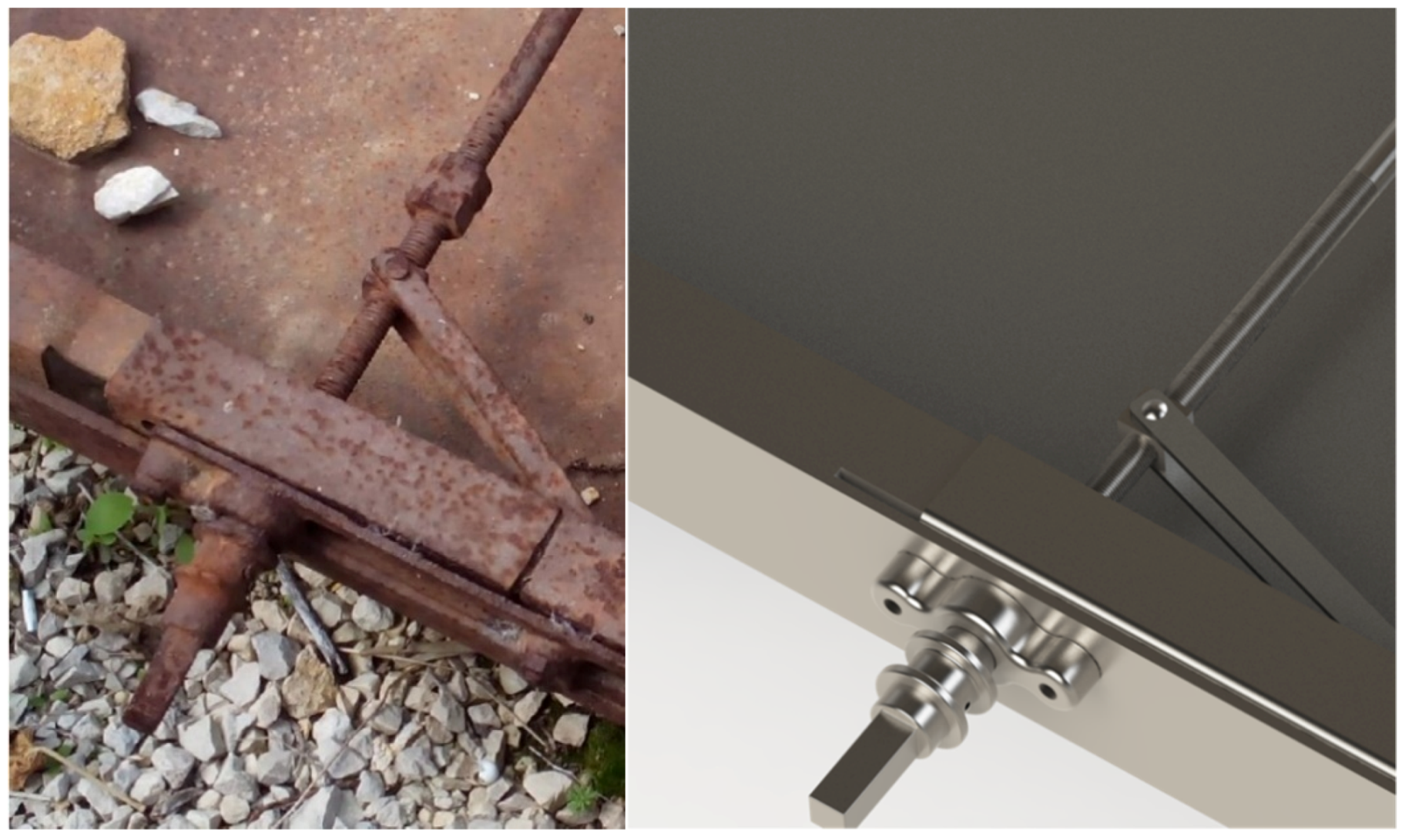
Likewise, this transport has a particular tensioning system for the drag roller, in which a connecting rod is made to move by means of a threaded shaft, which uniformly tightens the roller (Figure 14).
The threaded shaft, at one end with a right-hand thread and at the opposite end with a left-hand thread, performs a symmetrical movement of the connecting rods, thereby preventing the uneven tension of the conveyor belt that may cause its misalignment in the line of contact between the roller and the conveyor belt and would lead to its premature wear.
In order to understand this aspect, the decomposition of forces is represented in the line of contact between the roller and the conveyor belt (Figure 15).
With F as the traction force of the conveyor belt, it can be observed that, once there is a misalignment (α) of the line of contact between the roller and the conveyor belt, a component Fx1, appears, where Fx1 = F1 sin α, which is essential in the adjustment of the belts and, therefore, in their useful life.
In this way, the traction rollers are made up of alloyed steel supports at both ends that have a housing in which to locate the wooden roller, and, in addition to that housing, they have a cylindrical tip upon which the sprocket that moves it is fixed (Figure 16).
On the other hand, the composition of the tension rollers is similar: they consist of supports fixed to each end of a wooden roller that can rotate freely (Figure 17).
In the machine under study, each transport is made up of a traction roller and a tension roller, this being the most common constructive form of this type of short-length transport.
However, there is a small constructive difference between the traction rollers of the lower rise conveyor and the rest of the conveyors. In the case of reception and upper rise conveyors, these each have a traction roller that has a fixed point where the sprocket that makes it rotate is located, and another free point, which is fixed to the transport structure: this does not occur in the lower rise conveyor. This conveyor has a traction roller in which both ends have a fixed shaft upon which, on the one hand, a sprocket is housed that makes it rotate due to chain transmissions and, on the other hand, a gearbox is housed that transmits the rotation to the upper rise conveyor (Figure 18).

3.2.3. Sheaf Grouping and Knotting System

This is the most complex and sophisticated system of the machine due to the precision and synchronism that all its elements must possess for its proper operation. Once the sheaves are transported to the upper part, they pass through some plates (Figure 19) that, by means of an oscillating movement provided by a connecting rod/crank mechanism (Figure 20), group the sheaves so that the subsequent packaging is as homogeneous as possible.
Once the sheaves have passed through these plates, the well-packed sheaves pass through a system of compacting needles (Figure 21) which groups them together and compacts them. Once a sufficient number of sheaves have been grouped together, this needle system presses a trigger that activates the knotting system (Figure 22).
These compactor needles move in a four-bar system that creates an oscillating drag movement. By activating the knotting system, the clutch located in the knotting gearbox (Figure 23) rotates the knotter turn gear one full turn. In this complete rotation, an oscillatory movement of the needle occurs due to a movement of the connecting rod/crank type that exists between said gear and the shaft of the needle, by means of a cam.
Moreover, this movement is accompanied by the movement of the knotter elements (Figure 24), which perform the knotting thanks to the knotting control gear. During the entire rotation of the knotter shaft, the pushers rotate, which, in their final movement, push the knotted sheaves out of the machine.

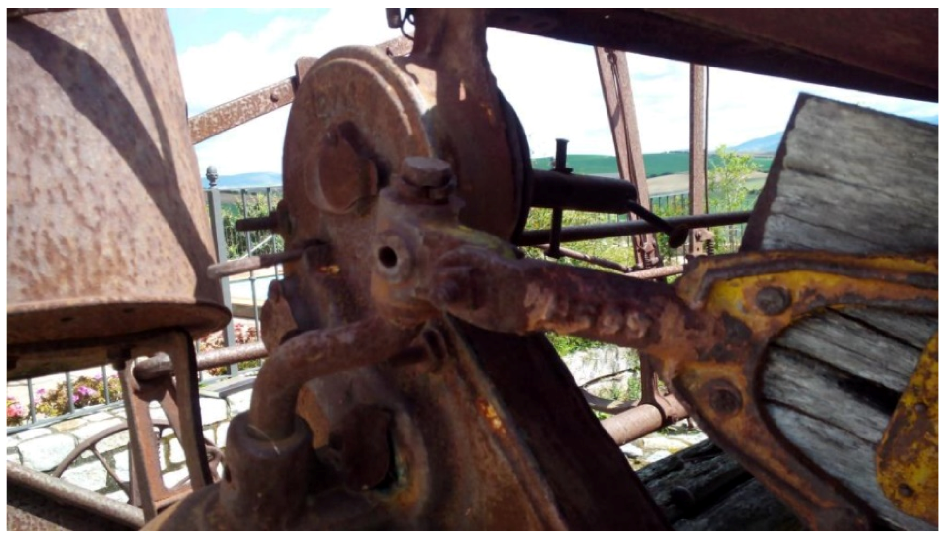
3.2.4. Mechanical Transmission and Drive Wheel System

Undoubtedly, the success of this machine resides in the way that the traction force of the draft animals is converted to give rise to all the movements of the various elements of this machine, thanks to a drive wheel that rotates a series of shafts using sprockets and gears. Figure 25 shows two views (back and front) of the mechanical transmissions. As can be observed, at the rear is a chain that distributes the movement to the different shafts of the various systems.
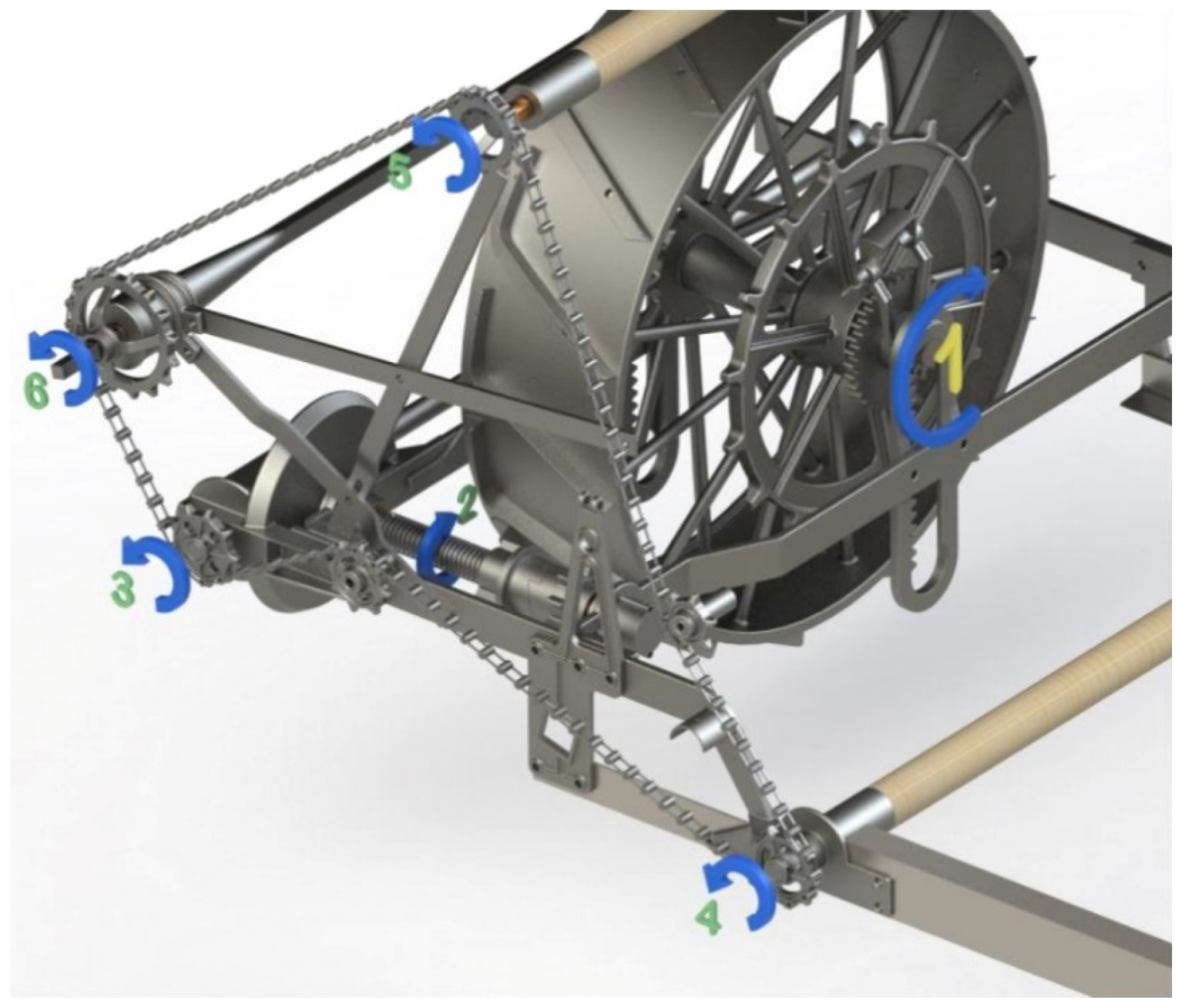
Figure 26 shows the description of the operation of the first set of elements of the transmission system.
This machine was initially hauled by draft animals, which made the drive wheel roll, together with the sprocket attached to it (turning movement 1). This turn was transmitted to a parallel shaft by means of a sprocket system with a clutch, which made it possible to paralyze the movements of the machine, even when the animals were still pulling it.
When said clutch was engaged, movement 1 was transmitted to said shaft, thereby generating a higher speed turn (turn movement 2), and subsequently this turn became turn movement 3 thanks to a group of bevel gears. This turning movement was responsible both for pulling the chain that transmits the turning movement to shafts 4, 5, and 6, and for generating the oscillating movements of the blades.
Turning movement 4 was responsible for moving the conveyor to where the sheaves fall, while turning movement 5 was in charge of driving the lower rise conveyor belt and, in turn, of transmitting the movement to the upper rise conveyor. Finally, turning movement 6 would be responsible for the movements of the knotting system, including both that of the compacting nails and of the needle and knotter.
In order to examine the operation of the second set of elements of the transmission system, the opposite side of the machine is observed (Figure 27).
As can be observed in Figure 27, turning movement 7 corresponds to turning movement 3 of Figure 26. This movement is converted into oscillating movement 8 by means of a connecting rod/crank mechanism.
The movement of the upper sheaf transport system corresponds to turning movement 10, which, as indicated, comes from the turning of the lower rise conveyor of the sheaves (turning movement 9). In turn, this turning movement 9 is transmitted by a gearbox that converts turning movement 9 into turning movements 10 and 11.
Likewise, turning movement 11 is converted into turning movement 12, which is responsible for making the sheaf pushers rotate by means of turning movement 13.
Finally, since the machine allows changes in height and inclination of the pushers, these latter shafts are connected by gimbal joints (Figure 28).

3.2.5. System of Adjustments Made by the Operator

Like most machines, this reaper-binder has regulators and adjustments by the operator that enable it to work optimally under various terrain circumstances.

Blade-Height Adjustment

The height of the blades is adjusted by means of two levers that raise and lower the wheels on which the machine moves when it is working: the drive wheel and the drag wheel (Figure 29).
In the case of the drive wheel, the height-adjustment lever moves a worm-crown gear that makes a gear that is integral with the axis of rotation of said wheel movement via a rack (Figure 30), thereby enabling its height to be modified.
In the case of the drag wheel, the height-adjustment system assumes the same form of operation, although, in this case, the wheel hub remains integral with the rack, and it is the sprocket that maintains its height, which varies the height with the turn of the crank.

Movement of Mechanical Systems

As indicated above, the machine has a clutch system (Figure 31) so that the mechanisms of the machine can start moving, as required. To this end, it has a lever with a horseshoe-shaped tip that allows the operator to operate a gear wheel that transmits the movement.

Regulation Levers

Once the machine is in operation, four adjustment levers are available from the operator seat (Figure 32), to control the inclination of the blades, the height and depth of the sheaf input pushers, and the operation of the knotting system.
Lever 1 is in charge of adjusting the inclination of the machine and with it the inclination of the blades with respect to the ground; lever 2 is responsible for changing the depth of the wooden pushers, by pushing the support point of the pushers either backwards or forwards; lever 3 is in charge of regulating the size of the sheaf to be knotted, by acting on the trigger that the knotter releases; finally, lever 4 is responsible for adjusting the height of the pushers according to the size of the sheaves to be reaped, for which the operator slides the lever downwards to raise the pushers, or slides it upwards to lower the pushers with the help of an extension spring.

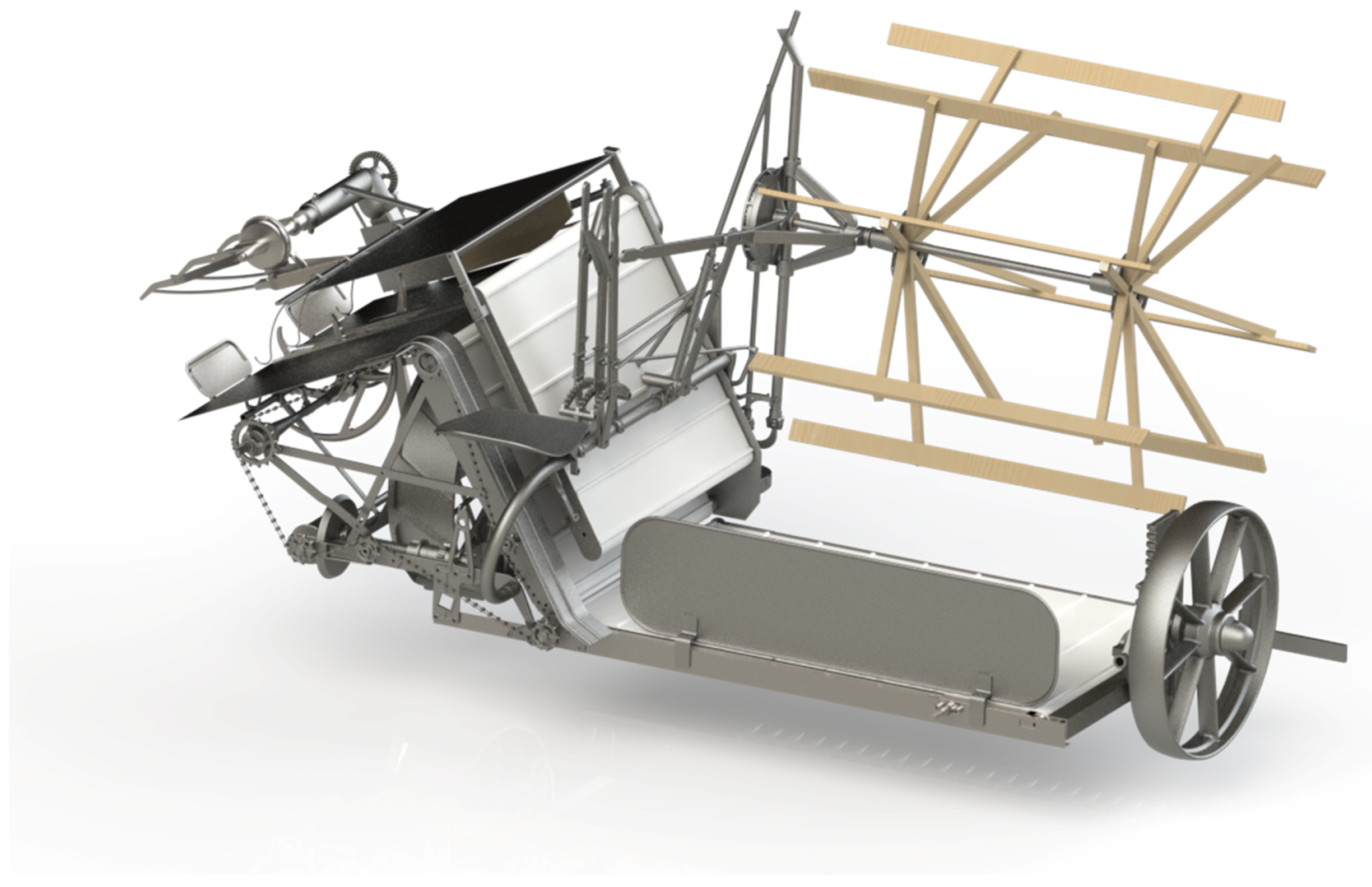
3.2.6. Final Assembly

Finally, a front (Figure 33) and back (Figure 34) view is shown once all the elements that comprise the reaper-binder have been assembled, after applying all dimensional, geometric, and movement restrictions, and the constraints of the joints, in order to obtain a 3D CAD model as true to reality as possible.

4. Conclusions

The reaper-binder designed by Cyrus Hall McCormick in the 19th century remains one of the most important inventions in the agricultural production of cereal. It revolutionized reaping since it could cover large areas of cultivation with a fraction of the manual labor, and constitutes the major precursor of the current combine harvester.
The main objective of this article involves obtaining 3D modelling and virtual reconstruction of this invention using the SolidWorks software. This research employs the point of view of industrial archaeology that strives to showcase and place a value on such an outstanding invention.
The methodology used in this research is based on the use of reverse engineering techniques. Therefore, from the original model encountered on an agricultural farm in the province of Cádiz (Spain), the principal measurements have been taken and dimensional sketches have been obtained, which have enabled the three-dimensional model of the aforementioned invention, and consequently its virtual reconstruction, to be attained.
Thus, after modelling each element of the set with the aforementioned parametric design and engineering software, it was necessary to establish restrictions (dimensional, geometric, and of movement) and constraints of the joints in order to obtain a coherent and fully functional 3D CAD model.
From the 3D CAD model, it has been possible to obtain the assembly plans with an indicative list of its components and their materials, which have greatly facilitated the understanding of the operation of the invention.
Among the main findings, it should be noted that the machine combines well-crafted chain and sprocket drives, which, together with a complex gearbox composed of parallel and bevel gears, render this reaper-binder a highly reliable machine. Furthermore, the inclusion of elements such as gimbal joints on shafts with possible misalignments, and of clutches to adapt the operation thereof to the needs of the operator, make it very versatile and functional without over-exerting the mechanics.
Although previously there existed reapers that included only the cutting part of the harvest with similar mechanics, the innovative inclusion of automatic knotting to form sheaves, represents the real revolution of this machine. From a technical point of view, the complex transmission systems of this design and the perfect synchronization achieved between all its parts can be considered an engineering work of art of its time. The combination of continuous oscillatory movements, such as that of sheaf compactors with intermittent movements as complex as that of the knotting mechanism, reveal the great work of innovative engineering behind this historical invention.
This research methodology can be applied to a multitude of historical inventions studied over the centuries, and it will enable us to testify to these notable contributions of technology to society by highlighting their legacy thanks to the techniques of modelling and virtual reconstruction as a first step towards a CAE study.

Author Contributions

Formal analysis, J.I.R.-S., G.D.R.-C. and Á.C.-G.; investigation, J.I.R.-S., G.D.R.-C., and Á.C.-G.; methodology, J.I.R.-S. and G.D.R.-C.; supervision, J.I.R.-S., G.D.R.-C., and Á.C.-G.; validation, Á.C.-G.; visualization, J.I.R.-S.; writing–original, draft, J.I.R.-S. and Á.C.-G.; writing–review and editing, J.I.R.-S. and Á.C.-G. All authors have read and agreed to the published version of the manuscript.

Funding

This research has received no external funding.

Acknowledgments

We sincerely appreciate the work of the reviewers of this article.

Conflicts of Interest

The authors declare there to be no conflict of interest.

References

  1. Sriwichai, T.; Junmahasathien, T.; Sookwong, P.; Potapohn, N.; Sommano, S.R. Evaluation of the Optimum Harvesting Maturity of Makhwaen Fruit for the Perfumery Industry. Agriculture 2019, 9, 78. [Google Scholar] [CrossRef] [Green Version]
  2. Hamido, S.A.; Morgan, K.T. Harvesting Method Affects Water Dynamics and Yield of Sweet Orange with Huanglongbing. Agriculture 2018, 8, 38. [Google Scholar] [CrossRef] [Green Version]
  3. Devetter, L.; Yang, W.Q.; Takeda, F.; Korthuis, S.; Li, C. Modified Over-the-Row Machine Harvesters to Improve Northern Highbush Blueberry Fresh Fruit Quality. Agriculture 2019, 9, 13. [Google Scholar] [CrossRef] [Green Version]
  4. Guerrieri, A.S.; Anifantis, A.S.; Santoro, F.; Pascuzzi, S. Study of a Large Square Baler with Innovative Technological Systems that Optimize the Baling Effectiveness. Agriculture 2019, 9, 86. [Google Scholar] [CrossRef] [Green Version]
  5. Bulgakov, V.; Pascuzzi, S.; Nadykto, V.; Ivanovs, S. A Mathematical Model of the Plane-Parallel Movement of an Asymmetric Machine-and-Tractor Aggregate. Agriculture 2018, 8, 151. [Google Scholar] [CrossRef] [Green Version]
  6. Andreasen, C.; Bitarafan, Z.; Fenselau, J.; Glasner, C. Exploiting Waste Heat from Combine Harvesters to Damage Harvested Weed Seeds and Reduce Weed Infestation. Agriculture 2018, 8, 42. [Google Scholar] [CrossRef] [Green Version]
  7. Ott, D. Producing a Past: McCormick Harvester and Producer Populists in the 1890s. Agric. Hist. 2014, 88, 87–119. [Google Scholar] [CrossRef]
  8. Ott, D. Producing a Past: Cyrus McCormick’s Reaper from Heritage to History. Ph.D. Thesis, Loyola University Chicago, Chicago, IL, USA, 2015. [Google Scholar]
  9. Winder, G.M. A trans-national machine on the world stage: Representing McCormick’s reaper through world’s fairs, 1851–1902. J. Hist. Geogr. 2007, 33, 352–376. [Google Scholar] [CrossRef]
  10. Rojas-Sola, J.I.; Fuente, E.D.L.M.-D.L. Agustín de Betancourt’s Optical Telegraph: Geometric Modeling and Virtual Reconstruction. Appl. Sci. 2020, 10, 1857. [Google Scholar] [CrossRef] [Green Version]
  11. Del Río-Cidoncha, G.; Rojas-Sola, J.I.; González-Cabanes, F.J. Computer-Aided Design and Kinematic Simulation of Huygens’s Pendulum Clock. Appl. Sci. 2020, 10, 538. [Google Scholar] [CrossRef] [Green Version]
  12. Rojas-Sola, J.I.; De la Morena-De la Fuente, E. The Hay Inclined Plane in Coalbrookdale (Shropshire, England): Geometric Modeling and Virtual Reconstruction. Symmetry 2019, 11, 589. [Google Scholar] [CrossRef] [Green Version]
  13. Rojas-Sola, J.I.; Galán-Moral, B.; De la Morena-De la Fuente, E. Agustín de Betancourt’s Double-Acting Steam Engine: Geometric Modeling and Virtual Reconstruction. Symmetry 2018, 10, 351. [Google Scholar] [CrossRef] [Green Version]
  14. Rojas-Sola, J.I.; De la Morena-De la Fuente, E. Digital 3D reconstruction of Betancourt’s historical heritage: The dredging machine in the Port of Kronstadt. Virtual Archaeol Rev. 2018, 9, 44–56. [Google Scholar] [CrossRef] [Green Version]
  15. Rojas-Sola, J.I.; De la Morena-De la Fuente, E. Geometric Modeling of the Machine for Cutting Cane and Other Aquatic Plants in Navigable Waterways by Agustín de Betancourt y Molina. Technologies 2018, 6, 23. [Google Scholar] [CrossRef] [Green Version]
  16. Rojas-Sola, J.I.; De la Morena-De la Fuente, E. Agustin de Betancourt’s Wind Machine for Draining Marshy Ground: Approach to Its Geometric Modeling with Autodesk Inventor Professional. Technologies 2016, 5, 2. [Google Scholar] [CrossRef] [Green Version]
  17. Principles of Seville. Available online: http://smartheritage.com/wp-content/uploads/2016/06/PRINCIPIOS-DE-SEVILLA.pdf (accessed on 20 April 2020).
  18. London Charter. Available online: http://www.londoncharter.org (accessed on 20 April 2020).
  19. Bethune, J.D. Engineering Design and Graphics with SolidWorks; Pearson: New York, NY, USA, 2017. [Google Scholar]
  20. Rojas-Sola, J.I.; De la Morena-De la Fuente, E. Agustín de Betancourt’s Double-Acting Steam Engine: Analysis through Computer-Aided Engineering. Appl. Sci. 2018, 8, 2309. [Google Scholar] [CrossRef] [Green Version]
  21. Rojas-Sola, J.I.; De la Morena-De la Fuente, E. Agustin de Betancourt’s Mechanical Dredger in the Port of Kronstadt: Analysis through Computer-Aided Engineering. Appl. Sci. 2018, 8, 1338. [Google Scholar] [CrossRef] [Green Version]
Figure 1. Photograph of the reaper-binder in its state of abandonment.
Agriculture 10 00322 g001
Figure 2. Plan of the ensemble of McCormick’s machine with an indicative list of its elements and materials (Elements 1–29).
Agriculture 10 00322 g002
Figure 3. Plan of the ensemble of McCormick’s machine with an indicative list of its elements and materials (Elements 30–47).
Agriculture 10 00322 g003
Figure 4. Cutting system with tines and blades (left) and its computer-aided design (CAD) three-dimensional (3D) model (right).
Agriculture 10 00322 g004
Figure 5. Limit positions of the blades.
Agriculture 10 00322 g005
Figure 6. Exploded view of the cutting system.
Agriculture 10 00322 g006
Figure 7. Rotating pusher system.
Agriculture 10 00322 g007
Figure 8. Sectional view of the sheaf pusher system.
Agriculture 10 00322 g008
Figure 9. Description of the movement of the rotating pushers.
Agriculture 10 00322 g009
Figure 10. Top view of the rise conveyor system of the sheaves.
Agriculture 10 00322 g010
Figure 11. Bottom view of the rise conveyor system of the sheaves.
Agriculture 10 00322 g011
Figure 12. Sectional view of the passage of the conveyor belts.
Agriculture 10 00322 g012
Figure 13. Description of the movement of the conveyor-belt tensioning system.
Agriculture 10 00322 g013
Figure 14. Conveyor-belt tensioning system (left) and 3D CAD model (right).
Agriculture 10 00322 g014
Figure 15. Decomposition of forces in the line of contact between roller and conveyor belt.
Agriculture 10 00322 g015
Figure 16. Traction roller.
Agriculture 10 00322 g016
Figure 17. Tension roller.
Agriculture 10 00322 g017
Figure 18. Traction roller of the lower rise conveyor.
Agriculture 10 00322 g018
Figure 19. Sheaf grouping system (left) and 3D CAD model (right).
Agriculture 10 00322 g019
Figure 20. Connecting rod/crank mechanism in the sheaf system.
Agriculture 10 00322 g020
Figure 21. System of knotting and compacting needles: top view (left) and bottom view (right).
Agriculture 10 00322 g021
Figure 22. Compacting needle (left) and trigger of the knotting system (right).
Agriculture 10 00322 g022
Figure 23. Knotting-system gearbox.
Agriculture 10 00322 g023
Figure 24. Elements of the knotter.
Agriculture 10 00322 g024
Figure 25. Mechanical transmissions: back view (left) and front view (right).
Agriculture 10 00322 g025
Figure 26. Description of the first set of elements of the transmission system.
Agriculture 10 00322 g026
Figure 27. Description of the second set of elements of the transmission system.
Agriculture 10 00322 g027
Figure 28. Gimbal joint of transmission of the rotating pushers.
Agriculture 10 00322 g028
Figure 29. Drive wheel (left) and drag wheel (right) with adjusting levers.
Agriculture 10 00322 g029
Figure 30. Drive-wheel rack.
Agriculture 10 00322 g030
Figure 31. Clutch system.
Agriculture 10 00322 g031
Figure 32. Adjustment levers.
Agriculture 10 00322 g032
Figure 33. Front view of the final assembly.
Agriculture 10 00322 g033
Figure 34. Back view of the final assembly.
Agriculture 10 00322 g034

