Article

Design of Hybrid-Electric Megayachts: The Impact of Operative Profile and Smart Berthing Infrastructures

1
Maritime Safety Research Centre, University of Strathclyde, Glasgow G4 0LZ, UK
2
Dipartimento di Ingegneria e Architettura, University of Trieste, 34127 Trieste, Italy
*
Author to whom correspondence should be addressed.
J. Mar. Sci. Eng. 2021, 9(2), 186; https://0-doi-org.brum.beds.ac.uk/10.3390/jmse9020186
Submission received: 15 January 2021 / Revised: 8 February 2021 / Accepted: 9 February 2021 / Published: 11 February 2021
(This article belongs to the Special Issue Zero Emission Shipping)

Abstract

:
Nowadays, sustainable navigation is becoming a trending topic not only for merchant ships but also for pleasure vessels such as motoryachts. Therefore, the adoption of a hybrid-electric propulsion system and the installation of on-board storage devices could increase the greenness of a megayacht. This paper analyses the performance of three commercial propulsive solutions, using a dynamic operative profile and considering the influences of the smart berthing infrastructures. Results compare the yearly fuel consumptions of the analysed configurations for a reference megayacht.

1. Introduction

Shipbuilding industry and shipping give a considerable contribute to air and sea pollution. International Regulations [1] specifically label certain sea areas as special, due to the risk of environment contamination caused by sea traffic. In these areas, the emission of Nitrogen Oxides ( N O x ), Sulphur Oxides ( S O x ) and Particulate Matter ( P M ) shall be below imposed specific thresholds. These Regulations are not compulsory for pleasure ships, but the growing environmental concern of luxury yachts shipowner strongly influences new buildings [2]. For such a reason, the fuel saving and the emission reduction become a major design driver, promoting the installation of technical solutions aimed to obtain a sustainable navigation.
In recent years many studies have focused on increasing the energy efficiency of ships through energy recovery from exhaust gases [3] or through the optimization of the performance of the diesel engines installed on board [4,5]. Moreover, many methods have been developed to preventively evaluate the energy efficiency index of a ship already during the early stage design [6,7]. Greater attention has certainly been paid to cruise ships due to their size and their close interaction with cities, but much has also been done for small cabotage vessels for passenger transport [8,9,10]. Anyway, in order to achieve the emission reduction goals, three strategies can be considered: the adoption of alternative fuels (Low Sulphur Fuel Oil, Liquefied Natural Gas, methanol, etc.), the air/sea emissions purification with on-board devices (scrubber, raiser, SCR, etc.) or the improvement of ship electrification exploiting energy storage and renewable energy sources. Ship electrification could give more flexibility to the propulsion system [11,12] and other advantages as noise reduction which are of utmost importance for a megayacht. The flexibility increase is given by the adoption of hybrid-electric power trains, providing propulsive power supply from different sources through an Integrated Power & Energy System (IPES) [13,14]. Moreover, the possibility of using shore connections when the vessel is berthed is further expanding the capability of hybrid-electric systems [15].
There are multiple technological solutions to set up a hybrid-electric propulsion system for marine industry [16] but, as in automotive sector, they can be grouped into two main categories: series and parallel configurations. Due to all the technical reasons set out above, as well as for the additional capabilities offered by a hybrid-electric propulsion system in terms of access to protected marine areas, maneuverability in port and comfort on board, shipowners are increasingly considering the adoption of these systems on board of luxury pleasure ships. Probably, another interesting aspect in favour of this design choice is also a significant reduction in fuel consumption against a modest increase in the total ship cost.
In the present work, three hybrid-electric propulsion system configurations (2 parallel and 1 series) will be compared with the conventional Diesel one for a reference megayacht. The comparison will be based on the total fuel consumption per one year of service. On this purpose, a dedicated study has been performed to evaluate in a novel way the operative profile of a megayacht, hypothesising multiple mode of use.
The impact of the berthing infrastructures has been considered, stressing that it is necessary that the Marinas reached by the megayacht shell be equipped with fast recharge devices for the embarked energy storage systems. This issue has been thoroughly discussed with the introduction of the Zero-Emission-Marina (ZEMar) concept [17,18]. If these infrastructures are present, the total fuel consumptions of the megayacht change, since the usage of generators during the berthing time can be neglected.
Based on these considerations, it will be possible to rank the greenness of the proposed solution both on the base of the owner preferred operative profile and of the berthing infrastructure in the megayacht’s cruising areas.

2. The Megayacht and the Analysed Propulsive Configurations

The vessel considered in this study is a megayacht having the main characteristic as reported in Table 1. The vessel (Figure 1) has been initially designed with a conventional diesel propulsion (configuration C0). However, during the design process, three additional hybrid-electric configurations (C1, C2 and C3) have been hypothesised by designers, to enhance the greenness of the pleasure unit. These configurations, provided by the shipbuilder, take into account specific constraints given by the costumer suppliers, stating that the vessel should be able to sail at cruise speed of 13.0 knots with only one propulsive engine working for configuration C1 or half of the diesel generators for C3 configuration. Also the battery pack sizing has been determined by designers according to fundamental constraints, considering the possibility to operate in Zero Emission Mode for 6–8 h, considering 1.5 h of low-speed (6 kn) navigation and 5–6 h stationing at anchor. It must be noticed that the designers did not predispose the systems with a shore connection.

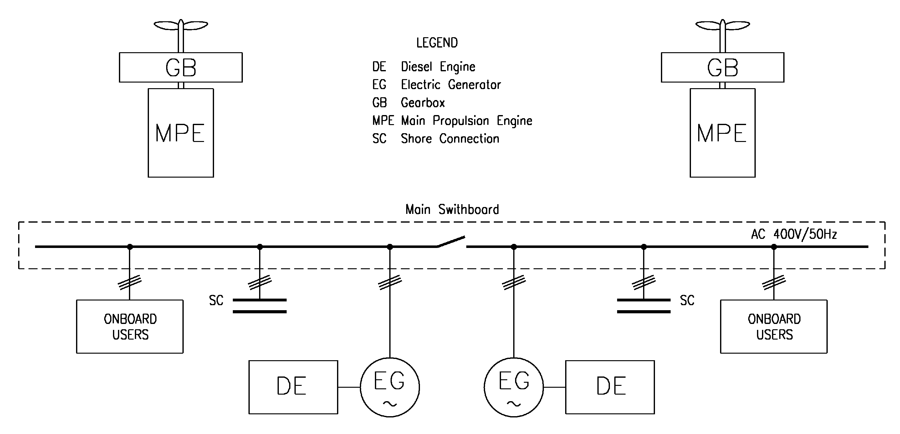
2.1. Configuration C0

The configuration is composed by a conventional propulsive set based on 2 main Diesel engines, 1268 kW each, connected to the two propellers. The electric power generation is completely separate from propulsion and is composed by three 300 kW Diesel generators. The generators have been dimensioned to supply all the on-board electrical loads with only one device running. A simplified scheme of the system is given in Figure 2. The conventional diesel propulsion is nowadays the standard application for megayachts and is here used as a reference to determine the possible enhancements that a hybrid electric propulsion could give.

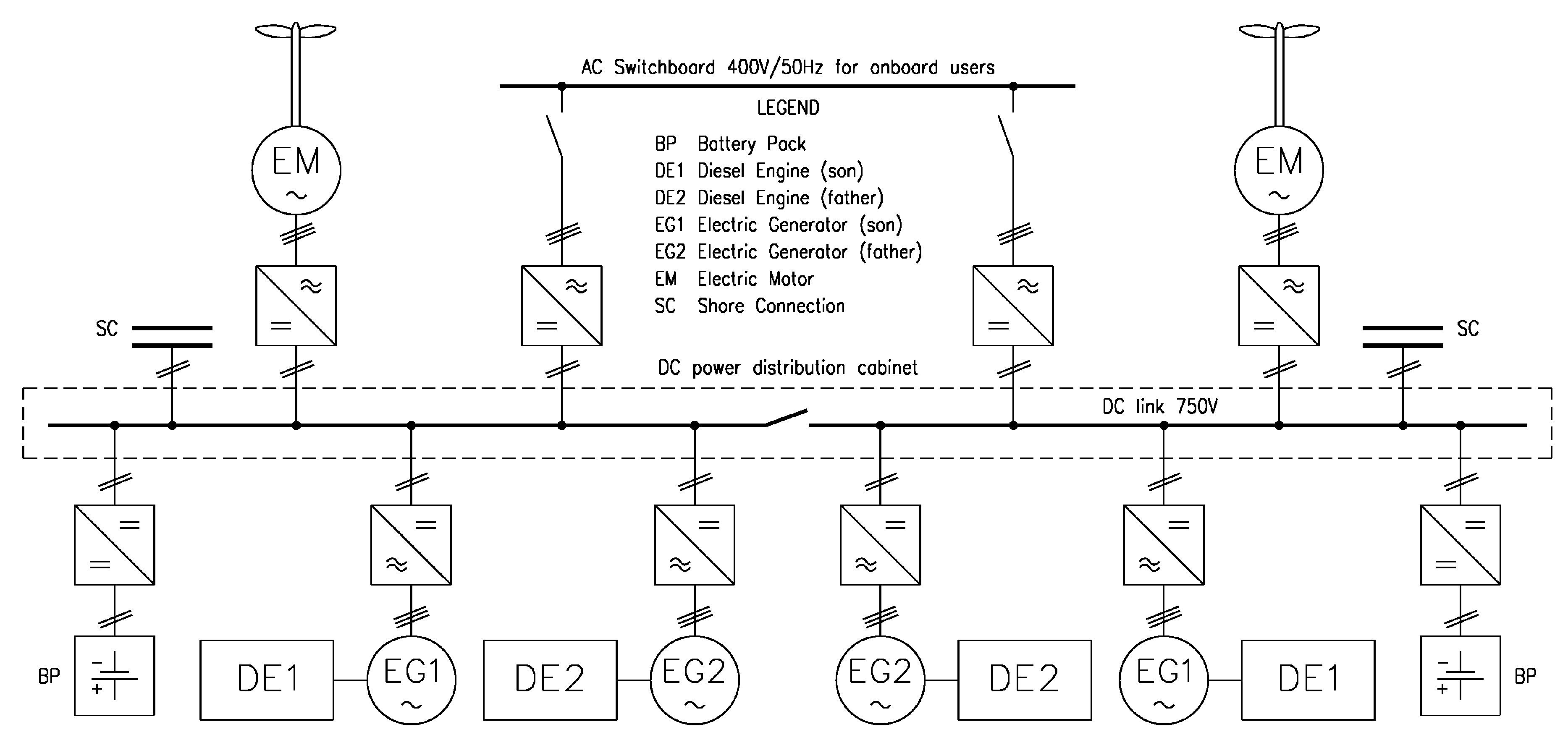
2.2. Configuration C1

The configuration is of the parallel hybrid type and is directly derived from configuration C0. It is based on 2 main Diesel engines, 1268 kW each, and two 300 kW Diesel generators. The system is completed by two battery packs with a total energy capacity of 2200 kWh. Two electric machines are connected to the Power Take-In/Take-Off (PTI/PTO) of the gearbox capable to generate up to 700 kW at 1800 rpm working as shaft generator or deliver to the propeller the same amount of power working as electric motor. A simplified scheme of the system is given in Figure 3. This hybrid-electric configuration did not allow the vessel to cruise in Zero Emission Mode (ZEM). In fact, the electric motors are dimensioned to grant the cruise speed while alimented by the Diesel engine of the other propulsive drive. The exploitation of energy from the portside drive to the starboard side one is granted by the 750 V DC bus.

2.3. Configuration C2

The configuration is also of the parallel hybrid type. The system architecture is derived form configuration C1; however, the sizes of the main Diesel engines and of the PTI/PTO are different. C2 configuration is based on 2 Diesel engines, 1080 kW each, thus, down-rated with respect to configuration C1. The generators and the battery pack are the same as the previous configuration, with two 300 kW Diesel generators and 2 battery packs with a total capacity of 2200 kWh. In this case, the PTI/PTO are capable to generate or deliver 450 kW at 1800 rpm. The concept scheme of this configuration is equal to the one reported in Figure 3 for the previous configuration. This hybrid-electric configuration did not allow to sail at cruise speed with only one Diesel engine running and the maximum speed V m a x can be obtained only with the electric machines working in PTI mode.

2.4. Configuration C3

The configuration is representative of a series hybrid. In this case the propulsion is performed by means of 2 electric motors, 1300 kW each. The electric power generation is performed by means of four Diesel generators of two different sizes: 2 of 800 kW (EG1 + DE1) and 2 of 1200 kW (EG2 + DE2). Also in this case, 2 battery packs with a total energy capacity of 2200 kWh are present. An overview of the configuration scheme is reported in Figure 4. Here, it can be seen how the generators are connected to the DC bus in the father/son configuration, this allows to grant the required power for propulsion by running only a couple of father/son engines.

3. Power Balance

For a preliminary sizing of the main components to be installed on-board, it is common practice to identify the possible operating modes of the megayacht and then evaluate the power demand of each user in the selected modes. In the present case, the following operating modes have been considered:
A.
Manoeuvring: in this mode, the vessel is inside the harbour/marina area and is approaching the berthing operations. During this phase, the main propulsion load is low, while almost all the loads is absorbed by manoeuvring equipments (rudders and thrusters).
B.
Cruise speed (day): in this mode, the vessel is sailing at the cruise speed V c during daily hours. Propulsion load is predominant but a consistent hotel load may be present.
C.
Cruise speed (night): in this mode, the vessel is sailing at the cruise speed V c during night hours. Compared to mode B, the hotel load is lower.
D.
Maximum speed: in this mode, the vessel is sailing at the maximum speed V m a x . This is the mode where all the available propulsive power is used, while hotel loads are comparable with mode B.
E.
Anchor stationing: in this mode the vessel is stationing at anchor. There are no propulsive loads and the electrical loads are covering all the energy demand including hotel and auxiliary equipment.
F.
Berthed: in this mode the vessel is berthed in a marine. There are no propulsive loads and the electrical loads are covering all the energy demand including hotel and auxiliary equipment.
There are multiple power user on-board and they can be grouped in dedicated categories with respect to the destination of use. For simplicity, in this study two macro-categories have been considered:
1.
Propulsive loads: this category includes only the loads needed for the propulsion at the different service speeds, means the loads of the Diesel engines in configuration C0.
2.
Electric loads: this category includes all the loads that are supplied by the diesel generators in configuration C0, thus including hotel loads, auxiliary and manoeuvring systems.
The above mentioned operating modes have different level of power demand, both for powering and electrical loads. These power levels should be determined since concept design phases, involving different kind of knowledge and different level of simplifications. In the following section an overview of the methods applied to determine these loads is given.

3.1. Propulsive Loads

The determination of the power needed for vessel propulsion is a relevant step for the determination of the environmental impact of a luxury yacht. Traditionally, propulsion is the main load of a ship during navigation, thus it has a strong impact on the total fuel consumption of the vessel and consequently on emissions. This is an issue strongly related to hull resistance and propulsive performance.
Several approaches can be used to evaluate the total resistance R T and afterwards the delivered power P D , considering different level of approximation according to the design stage of the vessel and consequently with the amount of information and details available for the ship. The higher fidelity method is given by model tests, alternatively Computational Fluid Dynamics (CFD) based on RANSE solutions can be used if the hull geometry is already defined; otherwise use should be made of empiric-statistic methods. For the megayacht under analysis, no information have been supplied regarding the vessel propulsive characteristics, except for the necessity to install a fixed pitch propeller with a maximum diameter D m a x of 1.9 m. For such a reason, here a method based on the Holtrop&Mennen procedure [19] has been used to determine R T in the following form:
R T = ( 1 + k ) R F + R A P P + R W + R B + R T R + R A
where all the components of R T , like wave resistance R W or bulb R B and transom R T R additional components are expressed as a function of speed and vessel geometric parameters. In the specific, frictional component R F is calculated according to ITTC-57 friction line, considering a speed dependent form factor ( 1 + k ) to account for viscous effects [20]. The hull appendages contribution R A P P has been considered including the presence of 2 spade rudders, 2 shafts with 2 V-shaped brackets, 2 fin stabilizers and a bow tunnel thruster. The allowance resistance R A takes into account the effect of hull roughness.
Applying the same method, also thrust deduction t, wake fraction w and relative-rotative efficiency η R have been determined, allowing to evaluate the optimal Wageningen B-series propeller characteristics for the speed V m a x of 17 knots. Defined the optimum propeller it is then possible to evaluate the P D at each vessel speed V s :
P D = P E / η D
where P E is the effective power (obtained as R T V s ), and η D is the propulsive efficiency obtained as follows:
η D = η 0 η R 1 t 1 w
where η 0 is the propeller open water efficiency, corrected also for cavitation effects [21]. It is convenient to adopt the shaft power P S instead of P D , just adding the shaft efficiency η S to the efficiency chain defined in (3). The obtained propeller and propulsive characteristics for the megayacht are summarised in Table 2, while the obtained speed-power curve is reported in Figure 5 together with propeller revolutions.
Even though with hybrid configurations also propulsive loads could be supplied by diesel generators or batteries, the distinction between electric and propulsive power has been kept constant in every configurations analysed in this study.
In Table 3 an overview of the power demand is given for the described operative modes. It can be noticed that the propulsive loads are predominant with respect to electric ones when the vessel is sailing at V c or V m a x .

3.2. Electric Loads

Electric loads estimation is not an easy task to be performed in the early design stage. To have a reliable value of the electric power absorbed, all the on-board users should be known with the associated nominal amount of energy absorbed during each operation mode. This is generally possible only in advanced design stages, where almost all auxiliary components installed on-board are already defined.
In the early-design stage use can be made of simplified statistical formulations based on own experience acquired on similar ships. Alternatively, for a more precise evaluation, a power request analysis can be performed in the various modes of use. Adopting this approach, the electric loads for the i th operating mode is determined as follows:
P E L i = j = 1 N u κ L i j κ U i j P N j
where P N j is the nominal absorbed power of each of the N u users in the j operating mode. κ L i j and κ U i j are two factors defined in 0 ; 1 ; κ L i j is a loading factor representing the power demand of the user in the operating mode, while κ U i j is a usage coefficient taking into account a continuous or intermittent demand of power in the selected operating mode.
The coefficients for the reference megayacht application have been provided by the designers, giving an estimation of the electric power for the six analysed operating modes. An overview of the total electric loads is given in Table 3.

4. Operative Profiles

The identification of the possible operating modes, and the consequent evaluation of the power demand of each user in the selected mode (as reported in Table 3), is a common practice for a preliminary sizing of the main components installed on-board. In this way, a static operative profile is determined for the vessel, assuming that the operative modes are performed without any time concatenations [22,23]. This assumption is acceptable for yacht designers, when the optimised functionality of the IPES is not known [24,25]. However, this kind of approach may lead to an initial underestimation of the environmental impact of the ship. In fact, to predict the vessel fuel consumption during the early-stage design it is advisable to consider a reliable operative profile for the megayacht. That means abandon the static operative profile in favour of a dynamic definition of the vessel operation, taking into account the time concatenation of the operating modes.

4.1. Dynamic Operative Profiles

It is quite complicated to exactly hypotheses an operative profile for a megayacht. While analysing other type of vessels, like merchant and passenger ships or also naval ships, the identification of a route or a mission profile is more straight forward [26,27,28,29,30]. For a megayacht, the operative profile is strongly influenced by the shipowner attitudes and it can be even more complicated in case of chartering (where different clients use the same vessel as they wish).
Therefore, the adoption of a predefined operative profile for a megayacht is not advisable, especially for the study of the environmental impact of the vessel. To overcome this issue, it has been decided to analyse multiple operative profiles, trying to simulate a wide spectrum of mode of use for the yacht. In the specific, one of the mostly influencing uncertainties for this process is to determine the ratio between the time spent in propulsion and the time spent stationing. Previous studies [24] stated that an equilibrate profile for a megayacht consists in 25% of operational time spent in navigation (modes A to D) and 75% stationing (modes E and F). In the present study, four operative profiles have been analysed, varying the ratio between navigation and stationing hours, considering a percentage of total operating time spent in navigation from 15% to 45% in step of 10%. To define the effective distribution between operating modes, relative fixed weights W have been applied:
W i j = T i T j j navigation , stationing i A , B + C , D   if   j   =   navigation E , F   if   j   =   stationing
where T is the time spent in each specific mode. Here, W A , n a v is 0.32, W B + C , n a v is 0.56 and W D , n a v is 0.12, while W E , s t a t is 0.51 and W F , s t a t is 0.49. The global overview of the operative profiles with the resulting relative time spent in each mode is given in Table 4.
From these starting distributions, the effective dynamic profiles have to be generated, to ensure a determined concatenation among different operative modes. This approach will be hereafter described.

4.1.1. Profile Generation

As main assumption, it has been hypothesised that a megayacht usually operates for 5 months during one year [24], resulting in approximatively 3600 h/year of use. During the remaining 7 months, the ship is berthed with limited personnel on-board, just for maintenance. Therefore, the analysis considers only the 5 months of effective operation.
The profile generation can be divided in the following steps:
1.
Divide the 3600 h of operation in step of 1 h.
2.
Start allocating all berthing hours (mode F) among N B long stays. N B is chosen randomly in 50 ; 150 , ensuring at list 5 h between consecutive stays.
3.
Allocate a manoeuvring hour (mode A) prior and after each N B berthing states, to ensure a low speed approach from and to the berthing place.
4.
Randomly allocate the other modes ensuring that also after an anchor stationing (mode E), a manoeuvre occurs.
This process is subject to a random sampling of the operative modes A, B + C , D and E according to the discrete occurrences reported in Table 4. As mentioned, no sampling is needed for mode F, because all the hours are located in the N B stays; for mode F, the randomness is given by the selection of N B . The distinction between mode B and mode C, having a joint occurrence, is made based upon the schedule, if it is between 7:00 AM and 19:00 PM mode B is considered, otherwise mode C is selected. Being the final operative profile function of 5 independent random variables, a high number of sub-scenarios should be generated to identify a sufficiently accurate estimate of the fuel consumptions, having a fair comparison among the 4 tested configurations. In this study 10 4 sub-scenarios have been generated for each condition, evaluating the fuel consumption according to the procedure hereafter described.

4.1.2. Fuel Consumption Calculation

The estimation of the fuel consumption requires to evaluate the rating of diesel engines during the different working hours. So, the power required by the individual users, summarised in Table 3, should be converted in the effective load supplied by the diesel engines (for propulsion and electric generation). Moreover, for hybrid-electric configurations also the batteries management should be considered, being the batteries able to provide energy or to absorb it according to the charge/discharge cycle.
The developed process is based on the following steps, applied at each consecutive hour in the sub-scenario:
1.
Determination of the average total loads to be supplied during the current hour of operation.
2.
Verification of the battery status, i.e., if they are available to supply energy or need to be recharged.
3.
Determination of the loads to be supplied by each diesel engine.
4.
Evaluation of the total fuel consumption for the considered hour.
The average total loads P T O T determination requires to evaluate the efficiency chain that intercourse between users and power sources. There are components that have an effect on the mechanical power and other components that have an effect on the electrical power. The main components considered in this study are the gearboxes, the electrical machines and the frequency converters. For the gearbox efficiency η g , a linear dependence has been considered between 0 and η g M A X for loads up to the 20% of the maximum power, setting η g M A X to 0.981 for standard configurations and to 0.967 for parallel hybrid ones. For higher loads η g remains constant. For the electrical components, reference values have been provided by manufacturers. Then, P T O T during 1 h is determined according to:
P T O T 1 h = P S η g + i = 1 N u P E L i η E L
where P E L values have been determined with (4) and η E L is the electric efficiency of the considered configuration. With the P T O T 1 h it is possible to estimate the energy to be supplied for the considered hour of operation. This value must be compared with the state of charge (SOC) of the battery packs. If the batteries are capable to supply it, all the energy is given by the battery packs until they reach a SOC around 10%. After batteries must be recharged up to recover a SOC above 90%. The remaining energy is supplied by diesel engines, forcing a sequential loading of the units to avoid ratings under 30% when possible. The final fuel consumptions are obtained considering the SFOC curves provided by the manufacturers as function of engine load. This simplified power system management has been adopted to allow the vessel working in ZEM as required by designers.
For each 10 4 sub-scenarios of the 4 operative profiles the yearly fuel consumption has been determined considering the 4 propulsive configurations C0, C1, C2 and C3, resulting in 16 × 10 4 simulations. An example is thoroughly described in Figure 6 for configuration C1, and it is possible to observe the data dispersion and the differences between the mean value of the dynamic analysis, compared to the conventional static value resulting in 20.7 t less of fuel. In Figure 7 it is possible to note that the fuel consumption obtained with the dynamic analysis follows a Normal distribution and the static value of the analysis is outside a 95% confidence interval around the mean dynamic value. The same trend reported for configuration C1 has been found for all the tested configurations. This is highlighting the importance to include also a possible battery cycle simulation (even though it is simplified) during the fuel consumption determination process.
A detailed overview of the results is reported in Table 5 and Figure 8. It is worth to be noted that more the yacht is used for navigation, less the hybrid-electric configurations give benefits in terms of fuel consumption. In particular, configuration C3 presents consumptions higher than the conventional configuration C0 for all the analysed operative profiles. The advantages in terms of fuel consumptions remains around 4.9% for C1 and 6.3% for C2, taking into account the Profile 2 (the most suitable for a luxury megayacht [31]).

5. Smart Berthing Infrastructures

In order to increase the advantages in terms of fuel consumption of the tested hybrid-electric configurations, it is essential to decrease the use of diesel generators to recharge the batteries, exploiting berthing facilities as shore connections. This possibility is of paramount importance in particular for megayachts that spend most of their lifetime berthed. Therefore, it is necessary that Marinas reached by megayachts shall be equipped with fast recharge devices for the embarked energy storage system, thus the ZEMar concept [17].

5.1. The ZEMar Concept

The Zero Emission Marina is a concept consequent to the Zero Emission Mode navigation and can be considered an appealing innovative target for future marinas. ZEMar may be achieved by the adoption of a local smart grid [32], able to provide the following advanced services with respect to standard berthing infrastructures:
a.
Fast recharge capabilities for onboard energy storage systems.
b.
Optimal management and exploitation of renewable energy sources for the supply of Alternative Maritime Power (AMP) installed in or nearby the Marina (e.g., photovoltaic or wind power plants).
c.
Additional supply of ancillary services, as local buffer energy storage to external distribution network.
The first two aspects are extremely interesting for the megayachts owners, as they can ensure or increase the greenness of the vessel. The latter could be an attractive source of profit for the Marina owner, increasing the appeal of the structure. However, ZEMar requires the reconfiguration of conventional marina’s energy system, taking into account the green yachts onboard energy distribution. The modern onboard energy system of hybrid-electric megayachts is based on a low voltage direct current (LVDC) distribution. Therefore, it is convenient to adopt the same type of energy distribution for the Marina in order to properly integrate the two energy systems [33,34]. This allows also an easier exploitation of renewable resources as DC photovoltaic [35] and wind power plants. In fact, in the last few years there has been a significant increase in private users able to feed into the grid electricity produced through the exploitation of renewable sources. The diffusion of multiple distributed generation plants has led to the subdivision of the various users into active and passive ones. The main consequence for the grid operators was the uncertainty about the amount of energy injected and withdraw from the grid itself. To meet the demand for flexibility in managing the network, measurements and telecommunication technologies have been introduced. This is how the modern smart grid was born. Smart grid is an electrical network capable of self-regulating through a continuous bidirectional exchange of digital information among various connected users.
In compliance with IEEE 1547.4 standard [36], the definition of microgrid was deducted from the smart grid as a set of utilities, energy storage and distributed generation systems, managed through a smart local control. In the automotive sector, this concept has already been studied and applied, as evidenced by the presence of a much-branched network of e-charging stations for cars [37,38,39]. In the maritime sector, despite the beneficial effects in terms of reducing emissions offered by cold ironing and AMP is evident, the high investments required are slowing down the smart revolution of port electricity networks. Currently, for the Marinas the issue is different because many of the typical smart microgrid devices are already present; e.g., photovoltaic panels on the parking lots’ canopies, e-charging stations for the shore connection on the docks, energy storage systems onboard the berthed vessels and wind micro-turbines on the roofs of clubhouses. The “only” missing part is the development of a new energy management system.
The fundamental component for the smart revolution of Marinas is the bidirectional smart meter AMM (Automatic Metering Management). This type of smart meter supports two-way communication between the electrical grid and the various users. AMM is able to communicate with the interface protection device through Power Line Communication (PLC) or through a dedicated communication protocol and even wireless. Thank to this capability, AMM will enable real-time reading of data related to energy consumed and fed into the grid. In addition, it will also be able to carry out self-diagnostic, fault reporting and analysis of the quality of the electricity supplied.
As mentioned before, to increase the efficiency of the ZEMar, it will be appropriate to adopt an energy distribution in DC. International standards are driving the voltage value of these microgrids to 1000 V. Only one electronic AC/DC static converter will be used for the connection between the Marina and the external grid [40]. Each recharging point will be equipped with a specific battery charger and an AMM smart meter always communicating with the vessels’ battery management system. Depending on the size of the vessel to be recharged, different types of e-charging stations, complying with the IEC 80005-3 [41], can be used, having 16 A, 125 A, 250 A and 600 A.
Figure 9 shows the block diagram of a ZEMar. For simplicity of representation, only one charging point has been detailed. The diagram shows also the presence of an Interface Protection Device (IPD), which receives signals from all the connected components and manages them efficiently [42]. Specifically, IPD acquires the measurements and information from the various connected electrical devices and consequently manages the opening and closing of each release circuit. From an electrical protection point of view, it must ensure maximum/minimum frequency and voltage protection, verification of signal quality and remote tripping capability. As for the e-charging stations, the photovoltaic and wind plants will also be connected to the ZEMar microgird through AMM.
Compared to a traditional Marina, there are further advantages for a potential investor:
a.
Drop of global pollutant emissions due to fossil sources energy exploitation.
b.
Reduction of energy purchasing costs from the Distribution System Operator(DSO).
c.
Possibility to sell storage service to the DSO, using also berthed yachts as additional capacity.
The redesign of the Marina energy system may lead to consider the ZEMar as a energy hub for the DSO, characterized by a time-varying capability, depending on the actual stored energy, strictly related to the number of green yachts berthed.
The possibility to consider the yacht as an integrated part of the Marina energy system, could be extremely attractive also for the shipowner. The connection between yacht and marina energy systems, using the yacht as an additional energy storage for the smart grid, may be convenient reducing conventional recharge costs. Besides, avoiding blind-charging periods on the yacht, a better battery-charging procedure is ensured.

5.2. ZEMar Impact on Megayacht Consumptions

If the above mentioned infrastructures are present, the total fuel consumption of the megayacht changes, reducing the usage of on-board Diesel generators during the berthing time. In order to evaluate the real advantages given by the ZEMar berthing infrastructures, an additional operating mode G (Berthed in ZEMar) has been introduced, having the same power demand of mode F. Then, additional simulations have been carried out, assuming that a certain percentage of the berthing hours are spent in a ZEMar (from 10% to 50% in step of 10%). Table 6 reports the results of the dynamic simulations for the three hybrid-electric configurations of the megayacht. In Figure 10 the specific example with the 30% of the berthing time in a ZEMar is reported, where configuration C2 presents a reduction of 10.8% with respect to C0 for Profile 2. The additional results highlight that the stationing in a ZEMar could give effective benefits in reducing total fuel consumption of the megayacht. It is interesting to note that for Profile 1 and Profile 2, also configuration C3 becomes favourable with respect to C0.

6. Conclusions

The paper describes the comparison, in terms of yearly fuel consumption, among four different energy system configurations for the propulsion and energy generation on-board of a megayacht. The conventional Diesel propulsion system C0 is analysed besides two parallel-hybrid (C1 and C2) systems and a series-hybrid (C3) one. A novel procedure to determine a dynamic operative profile of the megayacht has been developed, allowing to consider the concatenation among operating modes during one year of service. Besides, different operative profiles have been investigated, changing the ratio between the time spent stationing and the one spent sailing. This allows to investigate the influence of smart berthing facilities on the total fuel-oil consumption of a megayacht. The case study on a 72 m megayacht has been performed and presented, evaluating the fuel consumptions for all the simulated configurations.
Thanks to the proposed dynamic profile methodology it is possible to compare different hybrid-electric propulsive configurations evaluating in a more detailed way the total fuel-oil consumption since the early-stage design. For the operative profile of the reference megayacht, the advantages given by the adoption of a hybrid-electric propulsive solution are substantial only in case a smart berthing infrastructure (ZEMar) is exploited. Obviously, a smart berthing infrastructure shall be equipped with green energy generation systems. Otherwise, the environmental benefit will be not significant, resulting only in a relocation of pollutants.

Author Contributions

Conceptualization, F.M. and V.B.; methodology, F.M. and V.B.; software, E.G. and F.M.; formal analysis, F.M., E.G. and V.B.; investigation, E.G. and F.M.; data curation, F.M. and E.G.; writing—original draft preparation, F.M.; writing—review and editing, V.B., A.M. and F.M.; visualization, V.B. and F.M.; supervision, A.M.; funding acquisition, V.B. and A.M. All authors have read and agreed to the published version of the manuscript.

Funding

This research received no external funding.

Institutional Review Board Statement

Not applicable.

Informed Consent Statement

Not applicable.

Data Availability Statement

Not applicable.

Conflicts of Interest

The authors declare no conflict of interest.

Abbreviations

The following abbreviations are used in this manuscript:
ACAlternate Current
AMMAutomatic Metering Management
AMPAlternative Maritime Power
BPBattery Pack
CFDComputational Fluid Dynamics
DEDiesel Engine
DCDirect Current
EGElectric Generator
EMElectric Motor
IPDInterface Protection Device
IPESIntegrated Power and Energy System
ITTCInternational Towing Tank Conference
PLCPower Line Communication
PMParticulate Matter
PTIPower Take In
PTOPower Take Off
RANSEReynolds Averaged Navier-Stokes Equations
RMSRoot Mean Square
SFOCSpecific Fuel Oil Consumption
SOCState Of Charge
ZEMZero Emission Mode
ZEMarZero Emission Marina

References

  1. IMO. International Convention for the Prevention of Pollutions from Ships, Regulations 13–14, Annex VI; Technical Report, MARPOL; IMO Publishing: London, UK, 2018. [Google Scholar]
  2. Ruggero, V. Study on the evolution of large yacht project and construction as consequence of environmental rules. Procedia Manuf. 2020, 42, 30–34. [Google Scholar] [CrossRef]
  3. Altosole, M.; Campora, U.; Laviola, M.; Zaccone, R. High efficiency waste heat recovery from dual fuel marine engines. In Technology and Science for the Ships of the Future, Proceedings of the NAV 2018: 19th International Conference on Ship and Maritime Research, Trieste, Italy, 20–22 June 2018; IOS Press: Amsterdam, The Netherlands, 2018. [Google Scholar]
  4. Altosole, M.; Campora, U.; Figari, M.; Laviola, M.; Martelli, M. A diesel engine modelling approach for ship propulsion and real-time simulators. J. Mar. Sci. Eng 2019, 7, 138. [Google Scholar] [CrossRef] [Green Version]
  5. Dodero, M.; Bertagna, S.; Marinó, A.; Bucci, V. Performance in-live of marine engines: A tool for its evaluation. Appl. Sci. 2020, 10, 5707. [Google Scholar] [CrossRef]
  6. Mocerino, L.; Rizzuto, E. Computer model application to the evaluation of energy efficiency measures for cruise ships. In Sustainable Development and Innovations in Marine Technologies, Proceedings of the 18th International Congress of the International Maritime Association of the Mediterranean IMAM 2019, Varna, Bulgaria, 9–11 September 2019; CRC Press: Boca Raton, FL, USA, 2020. [Google Scholar]
  7. Mocerino, L.; Rizzuto, E. Preliminary approach to the application of the environmental ship index. In Sustainable Development and Innovations in Marine Technologies, Proceedings of the 18th International Congress of the International Maritime Association of the Mediterranean IMAM 2019, Varna, Bulgaria, 9–11 September 2019; CRC Press: Boca Raton, FL, USA, 2020. [Google Scholar]
  8. Ruggiero, V. New methodology to approach project of small hybrid propulsion passenger ferries for italian scenario. In Proceedings of the International Symposium on Power Electronics, Electrical Drives, Automation and Motion SPEEDAM 2020, Naples, Italy, 24–26 June 2020. [Google Scholar]
  9. Bucci, V.; Marinó, A.; Businaro, A. The new hybrid small pasenger vessel for the Venice Lagoon. In Proceedings of the 18th International Conference on Ships and Shipping Research NAV 2015, Lecco, Italy, 24–26 June 2015. [Google Scholar]
  10. Bucci, V.; Mauro, F.; Marinó, A.; Bosich, D.; Vicenzutti, A.; Sulligoi, G. Integrated design of a hybrid-electric power system for coastal-navigation multi-purpose crafts. In Proceedings of the 12th International Conference on Ecological Vehicles and Renewable Energies EVER 2017, Belfort, France, 14–17 January 2017. [Google Scholar]
  11. Niessink, R. Electric propulsion optimization for fast yachts. In Proceedings of the 24th International HISWA Symposium on Yacht Design and Yacht Construction, Amsterdam, The Netherlands, 14–15 November 2016. [Google Scholar]
  12. Bucci, V.; Marinó, A. A new proposal for the propulsion of a hybrid motor-sailer catamaran. In Proceedings of the 17th International Conference on Ships and Shipping Research NAV 2012, Napoli, Italy, 17–19 October 2012. [Google Scholar]
  13. Vicenzutti, A.; la Monaca, U.; Bosich, D.; Bucci, V.; Marinó, A.; Sulligoi, G.; Pelaschiar, R. Early-stage design of shipboard integrated power systems: CSI-based multiple solutions comparison. In Proceedings of the IEEE Electric Ship Technologies Symposium, ESTS 2017, Washington, DC, USA, 15–17 August 2017. [Google Scholar]
  14. Altosole, M.; Campora, U.; Vigna, V. Energy efficiency analysis of a flexible marine hybrid propulsion system. In Proceedings of the International Symposium on Power Electronics, Electrical Drives, Automation and Motion SPEEDAM 2020, Sorrento, Italy, 24–26 June 2020. [Google Scholar]
  15. Sulligoi, G.; Bosich, D.; Pelaschiar, R.; Lipardi, G.; Tosato, F. Shore-to-Ship Power. Proc. IEEE 2015, 103, 2381–2400. [Google Scholar] [CrossRef]
  16. Geertsma, R.; Negenborn, R.; Visser, K.; Hopman, J. Design and control of hybrid power and propulsion systems for smart ships: A review of developments. Appl. Energy 2017, 194, 30–54. [Google Scholar] [CrossRef]
  17. Bucci, V.; Marinó, A.; Bosich, D.; Sulligoi, G. The design of a slow-cruising superyacht with zero emission navigation and smart berthing modes. In Proceedings of the 9th International Conference on Ecological Vehicles and Renewable Energies EVER, Monte-Carlo, Monaco, 25–27 March 2014. [Google Scholar]
  18. Boselli, A.; de Marco, C.; Mocerino, C.; Murena, L.; Quaranta, F.; Rizzuto, E.; Sannino, A.; Spinelli, N.; Xuan, W. Evaluating LIDAR sensors for the Survey of Emissions from ship at Harbour. Lect. Notes Civ. Eng. 2021, 64, 784–796. [Google Scholar]
  19. Holtrop, J.; Mennen, G. An approximate power prediction method. Int. Shipbuild. Prog. 1982, 29, 166–170. [Google Scholar] [CrossRef]
  20. Holtrop, J. A statistical resistance prediction method with a speed dependent form factor. In Proceedings of the SMSSH, Varna, Bulgaria, October 1988. [Google Scholar]
  21. Holtrop, J. A statistical Re-Analysis of Resistance and Propulsion Data. Int. Shipbuild. Prog. 1984, 31, 272–276. [Google Scholar]
  22. Georgescu, I.; Godjevac, M.; Visser, K. Efficiency constraints of energy storage for onboard power systems. Ocean Eng. 2018, 165, 239–247. [Google Scholar] [CrossRef]
  23. Bucci, V.; Marinó, A.; Bosich, D.; Sulligoi, G. Inland waterways gas-fuelled vessels: An innovative proposal of a hybrid ship for the European network. In Proceedings of the International Conference ESARS, Aachen, Germany, 3–5 March 2015. [Google Scholar]
  24. van Loon, P.; van Zoon, P. From operational profile to hybrid propulsion. In Proceedings of the 24th International HISWA Symposium on Yacht Design and Yacht Construction, Amsterdam, The Netherlands, 14–15 November 2016. [Google Scholar]
  25. Bucci, V.; Marinó, A.; Mauro, F. A new concept design solution for pleasure sailing yachts. In Proceedings of the MARTEC 2016-3rd International Conference on Maritime Technology and Engineering, Lisbon, Portugal, 4–6 July 2016. [Google Scholar]
  26. Su, C.; Liao, C. Ship electrical load analysis considering power generation efficiency. In Proceedings of the 2015 IEEE/IAS 51st Industrial Commercial Power Systems Technical Conference (I CPS), Calgary, AB, Canada, 6–8 May 2015; pp. 1–11. [Google Scholar]
  27. Gualeni, P.; Fiore, G.; Maggioncalda, M.; Marsano, G. Life Cycle Performance Assessment Tool Development and Application with a Focus on Maintainence Aspects. J. Mar. Sci. Eng. 2019, 7, 280. [Google Scholar] [CrossRef] [Green Version]
  28. Sui, C.; de Vos, P.; Stapersma, D.; Visser, K.; Ding, Y. Fuel Consumption and Emissions of Ocean-Going Cargo Ship with Hybrid Propulsion and Different Fuels over Voyage. J. Mar. Sci. Eng. 2020, 8, 588. [Google Scholar] [CrossRef]
  29. Zaccone, R.; Ottaviani, E.; Figari, M.; Altosole, M. Ship vojage optimization for the safe and energy-efficient navigation: A dynamic programming approach. Ocean Eng. 2018, 153, 215–224. [Google Scholar] [CrossRef]
  30. Menna, A.; Perra, F.; Altosole, M.; Figari, M.; Piastra, F. The influence of the operational scenarios on the propulsion system selection in the preliminary naval ship design. In Proceedings of the 18th International Conference on Ships and Shipping Research NAV 2015, Lecco, Italy, 24–26 June 2015. [Google Scholar]
  31. Roy, J.; Shallcross, P.; Hardy, A.; Burnay, S. Reducing the environmental impact of large yacht. In Proceedings of the RINA Superyacht Conference, Coventry, UK, 14–15 September 2011. [Google Scholar]
  32. Miceli, R. Energy management and smart grids. Energies 2013, 6, 2262–2290. [Google Scholar] [CrossRef] [Green Version]
  33. Tabari, M.; Yazdani, A. A DC distribution system for power system integration of Plug-In Hybrid Electric Vehicles. In Proceedings of the IEEE Power & Energy Society General Meeting, Vancouver, BC, Canada, 21–25 July 2013. [Google Scholar]
  34. Raveendran, V.; Shanthisree, S.W.; Swathy, K.; Nair, M.G.; Alvarez-Bel, C. Vehicle-to-grid ancillary services using intelligent green eectric vehicle charging infrastructure in smartgrid. Int. J. Power Energy Syst. 2020, 40, 18–28. [Google Scholar]
  35. Lughi, V.; Massi Pavan, A.; Quaia, S.; Sulligoi, G. Economical Analysis and Innovative Solutions for Grid Connected PV Plants. In Proceedings of the IEEE International Symposium on Power Electronics, Electrical Drives, Automation and Motion SPEEDAM, Ischia, Italy, 11–13 June 2008. [Google Scholar]
  36. IEEE. IEEE Guide for Design, Operation and Integration of Distributed Resource Island Systems with Electric Power Systems, IEEE Std 1547.4-2011; IEEE: Piscataway, NJ, USA, 2011. [Google Scholar]
  37. Andrade, F.; Cardenas, J.J.; Romeral, L.; Cusido, J. Modeling and studying of power flow in a parking lot with plug -in vehicles and the impact in the public utility. In Proceedings of the IEEE PES Innovative Smart Grid Technologies (ISGT), Washington, DC, USA, 16–20 January 2012. [Google Scholar]
  38. Koyanagi, F.; Yokohama, R. A priority order solution of EV recharger installation by domain division approach. In Proceedings of the 45th International Universities Power Engineering Conference UPEC2010, Cardiff, UK, 31 August–3 September 2010. [Google Scholar]
  39. Brenna, M.; Foiadelli, F.; Zaninelli, D. Power and energy estimation for Plug-In electric vehicles recharge in metropolitan area. In Proceedings of the 11th International Conference on Electrical Power Quality and Utilisation, Lisbon, Portugal, 17–19 October 2011. [Google Scholar]
  40. Hema, V.K.; Dhanalakshmi, R. Analysis of power sharing on hybrid AC-DC microgrid. In Proceedings of the 2014 Annual International Conference on Emerging Research Areas: Magnetics, Machines and Drives (AICERA/iCMMD), Kottayam, India, 24–26 July 2014. [Google Scholar]
  41. IEC. IEC/PAS 80005-3:2014 Utility Connections in Port-Part 3: Low Voltage Shore Connection (LVSC) Systems-General Requirements; International Electrotechnical Commission: Geneva, Switzerland, 2014. [Google Scholar]
  42. Guerrero, J.M.; Loh, P.C.; Lee, T.; Chandorkar, M. Advanced Control Architectures for Intelligent Microgrids - Part II: Power Quality, Energy Storage, and AC/DC Microgrids. IEEE Trans. Ind. Electron. 2013, 60, 1263–1270. [Google Scholar] [CrossRef] [Green Version]
Figure 1. The reference megayacht.
Jmse 09 00186 g001
Figure 2. Simplified scheme of the original configuration C0.
Jmse 09 00186 g002
Figure 3. Simplified scheme of the parallel hybrid configuration C1, this scheme is valid also for configuration C2.
Jmse 09 00186 g003
Figure 4. Simplified scheme of the series hybrid configuration C3.
Jmse 09 00186 g004
Figure 5. Speed-Power curve and propeller revolution rate for the reference megayacht.
Jmse 09 00186 g005
Figure 6. Simulation process of dynamic profiles for configuration C1.
Jmse 09 00186 g006
Figure 7. Fuel consumption results distribution for configuration C1.
Jmse 09 00186 g007
Figure 8. Total fuel consumption in one year comparison between the 4 configurations according to the different operating profiles.
Jmse 09 00186 g008
Figure 9. Block diagram representation of a Zero Emission Marina (ZEMar).
Jmse 09 00186 g009
Figure 10. Total fuel consumption in one year comparison between the 4 configurations according to the different operating profiles considering the 30% of berthing time in a smart Marina.
Jmse 09 00186 g010
Table 1. Reference megayacht main characteristics.
QuantitySymbolValueUnit
Length overall L O A 72.0m
Waterline length L W L 69.2m
BreadthB11.7m
DraughtT2.9m
Displacement Δ 1281.7ton
Maximum speed V m a x 17.0kn
Cruise speed V c 13.0kn
ZEM speed V Z E M 6.5kn
Table 2. Propeller and propulsive characteristics of the reference megayacht.
QuantitySymbolValueUnit
Propeller diameterD1.9m
Pitch diameter ratio P / D 1.034-
Blade area ratio A E / A 0 0.657-
No. propeller bladesZ5-
Maximum available power P M A X 2536kW
Maximum achievable speed V P M A X 17.33kn
Propeller revolutions at P M A X N356.6RPM
Wake fraction at V P M A X w0.103-
Thrust deduction at V P M A X t0.120-
Table 3. Power demand for the different megayacht operating modes.
ModePower (kW)
ElectricPropulsion
AManoeuvring276110
BCruise speed day hours258974
CCruise speed night hours201974
DMaximum speed2492346
EAnchor Stationing2550
FBerthed2380
Table 4. Modes subdivision in the considered operative profiles.
Mode% of Operative Time
Profile 1Profile 2Profile 3Profile 4
A4.8%8.0%11.2%14.4%
B + C8.4%14.0%19.6%25.2%
D1.8%3.0%4.1%5.4%
E43.4%38.0%33.2%28.1%
F41.6%37.0%31.9%26.9%
Table 5. Fuel consumptions for the different operative profiles and propulsive configurations.
Conf.Fuel Consumption per Year (Ton)
Profile 1Profile 2Profile 3Profile 4
C0316389462534
C1290370451531
C2287365443521
C3324401490573
Table 6. Consumptions of hybrid-electric configurations considering mode G.
Conf.% G ModeFuel Consumption Per Year (Ton)
Profile 1Profile 2Profile 3Profile 4
C110283364444527
20277357441522
30271351437518
40265347431514
50263343429513
C210279359437518
20274352433512
30267347430507
40263343423504
50260339419500
C310318397482571
20311390479565
30305383475559
40299379469557
50297374463553
Publisher’s Note: MDPI stays neutral with regard to jurisdictional claims in published maps and institutional affiliations.

