1. Introduction
Wind power offers an interesting source of energy, leading to the current development of onshore, nearshore and offshore wind farms. Compared to onshore, nearshore and offshore wind turbines benefit from a number of advantages such as limited visual impact, higher and more constant wind speed, and the possibility of using large capacity turbines, resulting in higher power generation. There are several foundation concepts for offshore wind turbines, which specifically depend on the loading, water depth and soil conditions: gravity-base; monopole, tripile, tripod, jacket or anchor for floating structures [
1,
2]. In the case of floating wind turbines, the structures are connected to the foundation system through several anchor lines and the cyclic load then acts in multiple directions, due to the combined action of wind and waves. In the particular case of mutualized anchor foundations for floating wind turbines, the foundations are also subjected to the phase shift between the loads generated in the adjacent anchored turbines. This study thus focuses on the case of piles as mutualized anchors for floating wind turbines, thus submitted to multidirectional lateral cyclic loads.
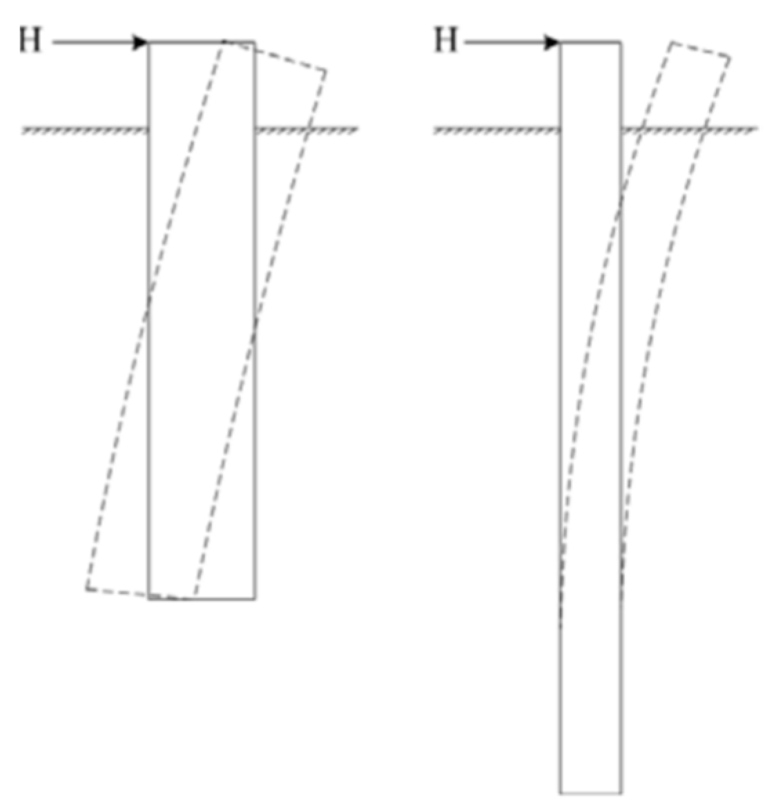
When a pile is subjected to lateral loads, one of the essential features is known to be the pile bending stiffness compared to the surrounding soil stiffness and strength. Short rigid piles are mainly submitted to displacement and rotation, whereas for flexible piles, the soil–pile behaviour is affected by the flexibility of the pile (
Figure 1).
Poulos and Hull (1989) [
3] defined the rigidity parameter R (Equation (1)), depending on the pile Young modulus
Ep and quadratic moment
Ip, and on the soil “stiffness”
Es. They suggested that a pile with a length less than 1.48 R behaves rigidly, and if the length exceeds 4.44 R, the pile behaves flexibly. However, one should note that the choice of a homogeneous soil stiffness
Es is still problematic in practice:
The piles under lateral load are traditionally designed using the
p–y curve concept [
4,
5], which formulates the soil response as uncoupled non-linear springs (Winkler approach), relating the soil pressure
p acting against the pile shaft and the corresponding lateral displacement
y of the pile. However, the concept has been developed based on semi-empirical relations for flexible piles under monotonic loading and has some limitations for large diameter piles, as particularly highlighted by numerical modelling approaches [
6,
7]. Indeed, when a pile behaves rigidly, a passive wedge of soil beneath the point of zero deflection will develop, an aspect which is not considered in the current methodology.
Furthermore, design methods of these offshore piles and their response to cyclic lateral loading are an important issue in the geotechnical engineering practice and has been addressed by several studies around the world, mainly focusing on mono-directional loading.
Among others, experimental testing studies in centrifuges have been reported in [
8,
9,
10]. Most of the studies are synthetized in the
SOLCYP Project recommendations [
11]. All these studies have highlighted the lateral displacement accumulation during the cycles. Based on field-scale piles, Lin and Liao (1999) [
12] proposed a logarithmic law as
where y
1 and y
N are the pile head lateral displacement at first loading and at Nth cycle, respectively, and α is a parameter which thus represents the displacement accumulation due to the cycles. This parameter α highly depends on the loading type, cyclic amplitude, pile installation, soil properties, pile embedment length and pile–soil relative stiffness. For instance, Verdure et al. (2003) [
13] presented a linear relationship of α value with the cyclic amplitude, based on the centrifuge tests of a flexible pile in a dry dense sand under one-way cyclic loading. They proposed α = 0.18 ΔH/H
max where ΔH is the cyclic amplitude and H
max is the maximum loading. They also mentioned that the load cycles have much more effect on the pile displacement when the maximum applied load is closer to the ultimate lateral static resistance of the pile. Concerning the effect of pile–soil relative stiffness, the effect of cycles is more important for flexible piles than for rigid piles [
14]. For rigid piles, the value of E
p I
p has no more influence [
11].
Based on the expression proposed by Rosquoët et al. (2007) [
15] obtained from experimental results on flexible piles in sand, the
SOLCYP recommendations [
11] propose the following logarithmic law for the case of intermediate or rigid piles in sand, thus also accounting for the pile bending stiffness:
where CR is a rigidity coefficient defined as
(Ep Ip)fl corresponds to the limit value of the pile bending stiffness Ep Ip for flexible piles and should be first assessed by analysing the effect of the pile bending stiffness on the pile head displacement under monotonic horizontal loading. (Ep Ip)fl corresponds to the value below which the bending stiffness has a large impact on the pile head displacement. For flexible piles, CR = 1. Hmax and Hc are, respectively, the maximum lateral load and half of the amplitude of the cyclic loading (see Equations (5) and (6)).
An alternative or additional approach to experimental and semi-empirical investigation consists of implementing numerical models. In this approach, special attention should be paid to the modelling of the soil (and pile–soil interface), by using relevant constitutive models, even under monotonic loading [
16]. A few numerical approaches under lateral cyclic loading have been proposed. For instance, Achmus et al. (2009) [
17] implemented an approach termed “degradation stiffness model” to account for long-term cyclic lateral loading of piles. Model parameters were assessed from cyclic triaxial tests results with up to 10
4 cycles, and numerical results were compared to test results of pile in sand, showing a good agreement. The numerical parametric study thus permitted to develop design charts.
Nevertheless, most of these studies under lateral cyclic loading focus on the case of mono-directional loading. The behaviour of the piles under lateral loading that varies in direction and amplitude has been little studied to date, and even less under cyclic loading conditions. Su and Li (2013) [
18] investigated the effect of multidirectional lateral loading using a finite-element modelling approach, by applying an imposed trajectory at pile head (with no unloading). They obtained that the lateral resistance of the pile is lower under multidirectional than under mono-directional loading. In this latter, the directions of the force increment vector and lateral displacement increment vectors are generally non-coaxial. Lovera et al. (2020) [
19] extended the framework of
p–y curve method to multidirectional loading, and they obtained a misalignment between load direction and total displacement when the loading direction changes.
Concerning the effect of multidirectional lateral loading under cyclic conditions, a few experimental studies were conducted. Mayoral et al. (2016) [
20] focused on the case of a pile in soft clay under seismic loading using an experimental modelling approach. They highlighted the influence of the cyclic loading path on the pile response and they noted that the concept of
p–y curve could not simply be applied in two orthogonal directions. Rudolph et al. (2014) [
21] performed centrifuge experiments of a large-diameter pile in sand, with up to 13,000 cycles and a variation of loading direction of 0°, 30°, 60° or 90°. They highlighted the significant increase in lateral displacement accumulation, even under load levels representative of serviceability conditions, which makes the current guidelines—as in the American Petroleum Institute (API) recommendations [
4]—non-conservative.
Experimental studies are complex to perform, expensive and time consuming, even more under complex loading paths, with cycles and loading direction changes, so that complete parametric studies under such complex and multiple conditions are difficult to conduct. Numerical studies thus can help understanding the behaviour under complex conditions and highlight governing features. Moreover, numerical studies allow accessing information difficult to obtain experimentally, such as the bending moment in the pile. However, no numerical study of pile subjected to lateral multidirectional cyclic loading has been reported in the literature to date.
The objective of this work was to develop a numerical approach to acquire knowledge concerning the system behaviour and governing parameters, in the case of multi-directional and cyclic lateral loading as encountered for mutualized anchoring piles. The aim was to be able to estimate the accumulated pile displacements, in particular at the mudline, and the accumulated pile rotation and/or bending, in such complex loading situations.
To achieve these objectives, a conceptual 3D numerical model using the commercial finite difference software Flac3D [
22] was developed, simulating the pile, the surrounding ground mass and their interface. Specific loading procedures are implemented to apply mono-directional and then multi-directional cyclic loadings. The multi-directional loading consists of varying the direction of the lateral load during the unloading–reloading process.
2. Materials and Methods for the Numerical Modelling
2.1. Model Specifications
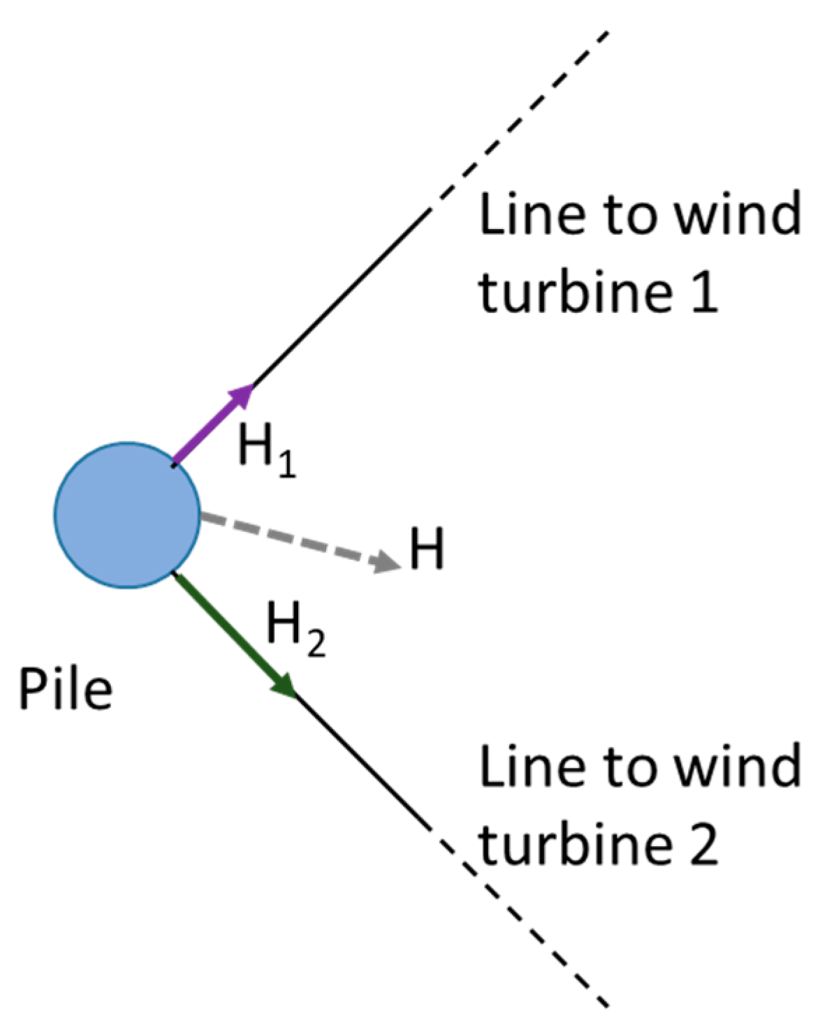
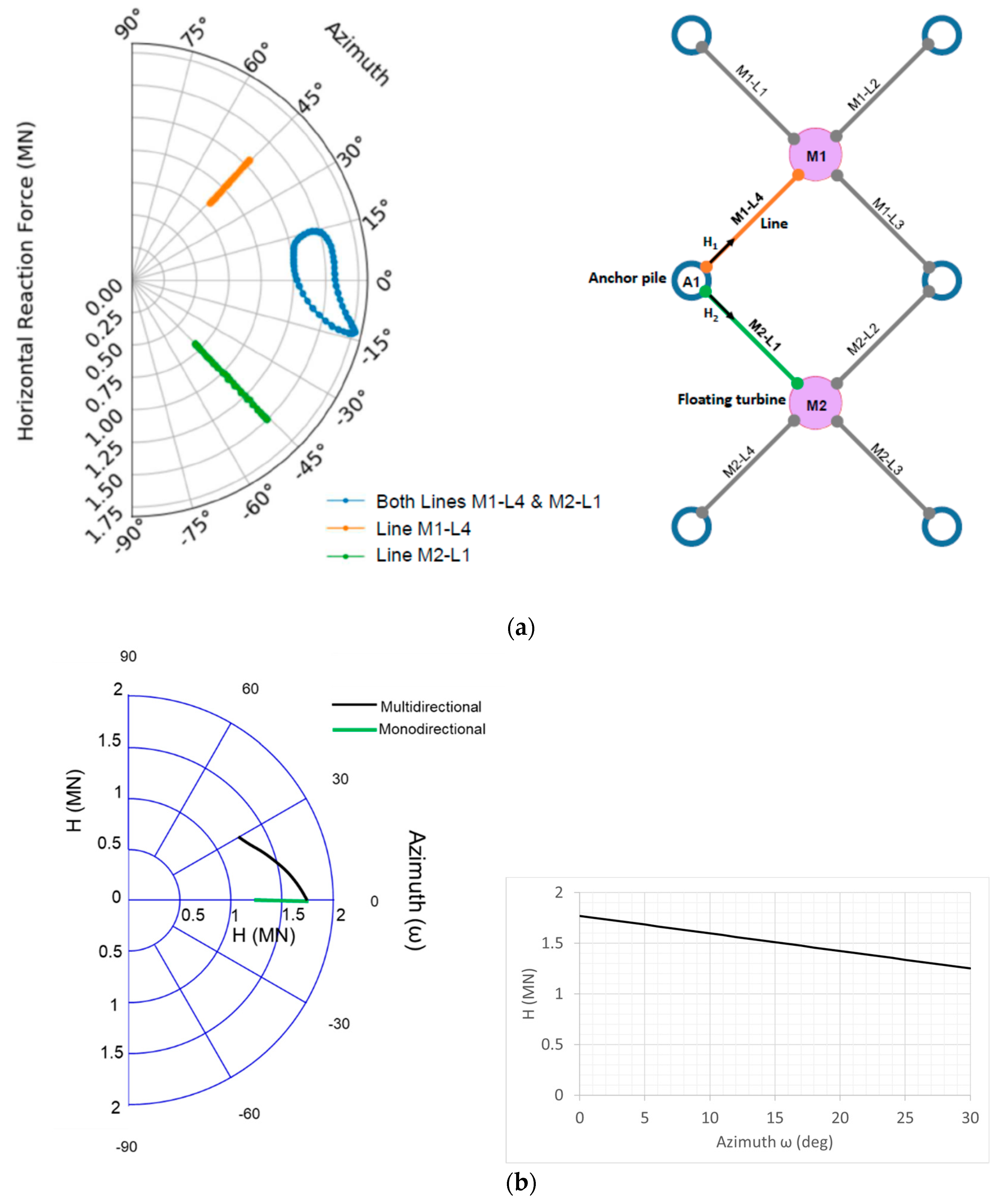
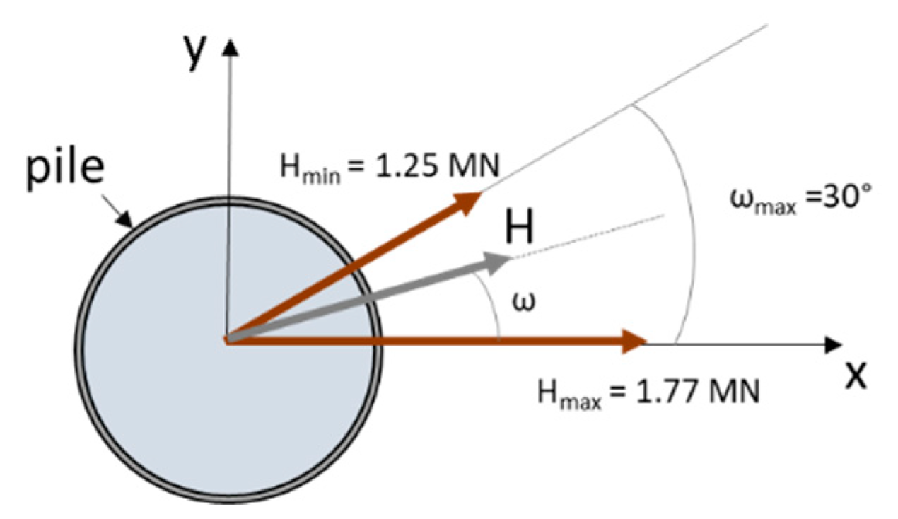
In the case of mutualized anchor piles for floating wind turbines, each pile was connected to several turbines (
Figure 2) and each turbine was connected to several piles. In the case depicted in
Figure 2, the horizontal load applied to a pile head (H) thus results from the tension applied by both lines (H
1 and H
2). H
1 and H
2 both vary in time, more or less independently from the other, thus resulting in a multidirectional cyclic vertical (not investigated here) and horizontal loading: H = f(ω, t), where ω is the loading direction (or azimuth) and t, time.
The reference case considered in this study is taken from a relevant case proposed by France Energies Marines [
23], in order to proceed with the development of the numerical model.
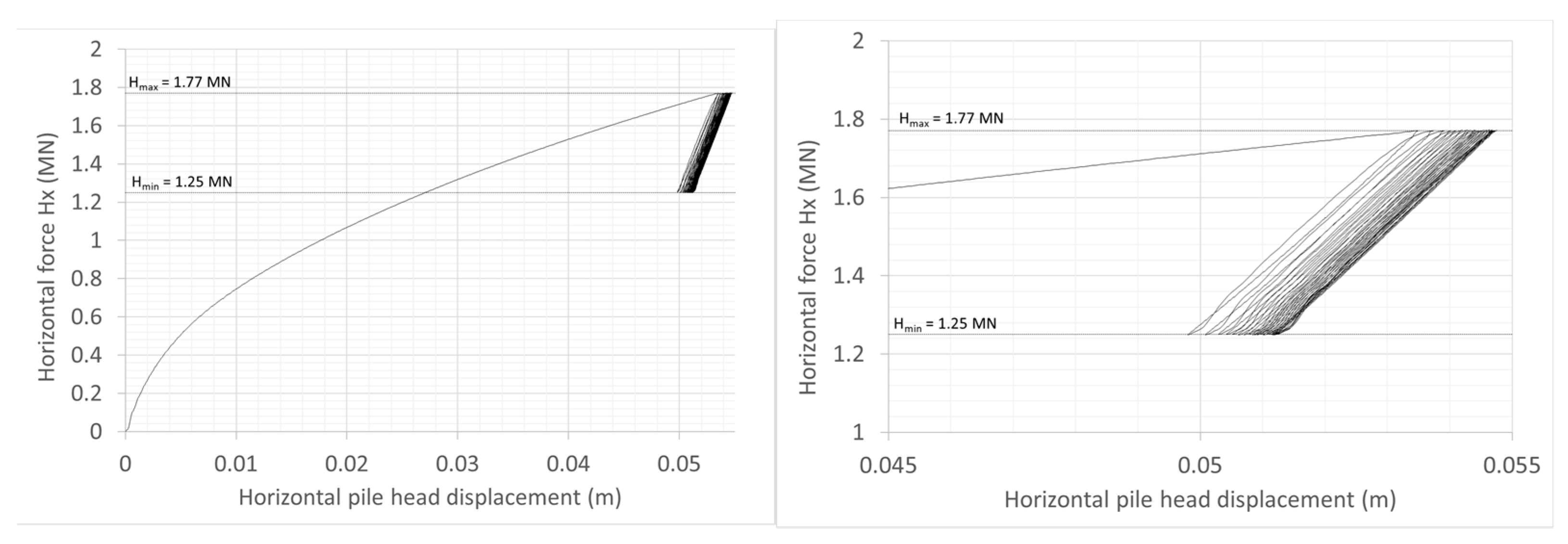
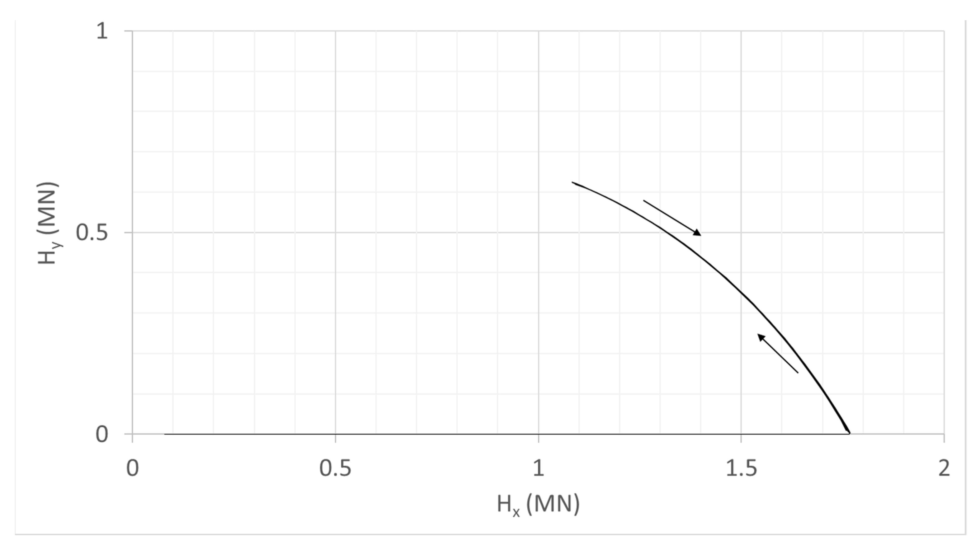
Figure 3a depicts this relevant case in terms of the horizontal loading on an anchored pile (named A1), induced by two anchored lines (M1-L4 and M2-L1) connected to two floating turbines (M1 and M2). In this case, the resulting horizontal force (H) at pile head varies between H
max = 1.77 MN down to H
min = 1.25 MN, with a change of force direction of 30° in a horizontal plane (azimuth change).
Figure 3b depicts the considered loading path H as a function of the azimuth ω adopted in the numerical study. In this exploratory study, unloading and reloading follow the same path. The case of the mono-directional loading of the same loading amplitude (H between 1.25 and 1.77 MN, thus with ω = constant, equal to 0° on
Figure 3b) is first considered in order to (i) proceed to a numerical model validation under a more “conventional” situation; (ii) highlight the impact of loading azimuth change on the pile response afterwards.
As an initial numerical parametric study, the impact of the average horizontal force and amplitude of mono-directional cycling loading (i.e., ω = 0°) is investigated beforehand.
The average lateral load
Hm and half-amplitude of cyclic loading
Hc are defined as
The reference case corresponds thereby to
Hm = 1.51 MN and
Hc = 0.26 MN. The
Hc/
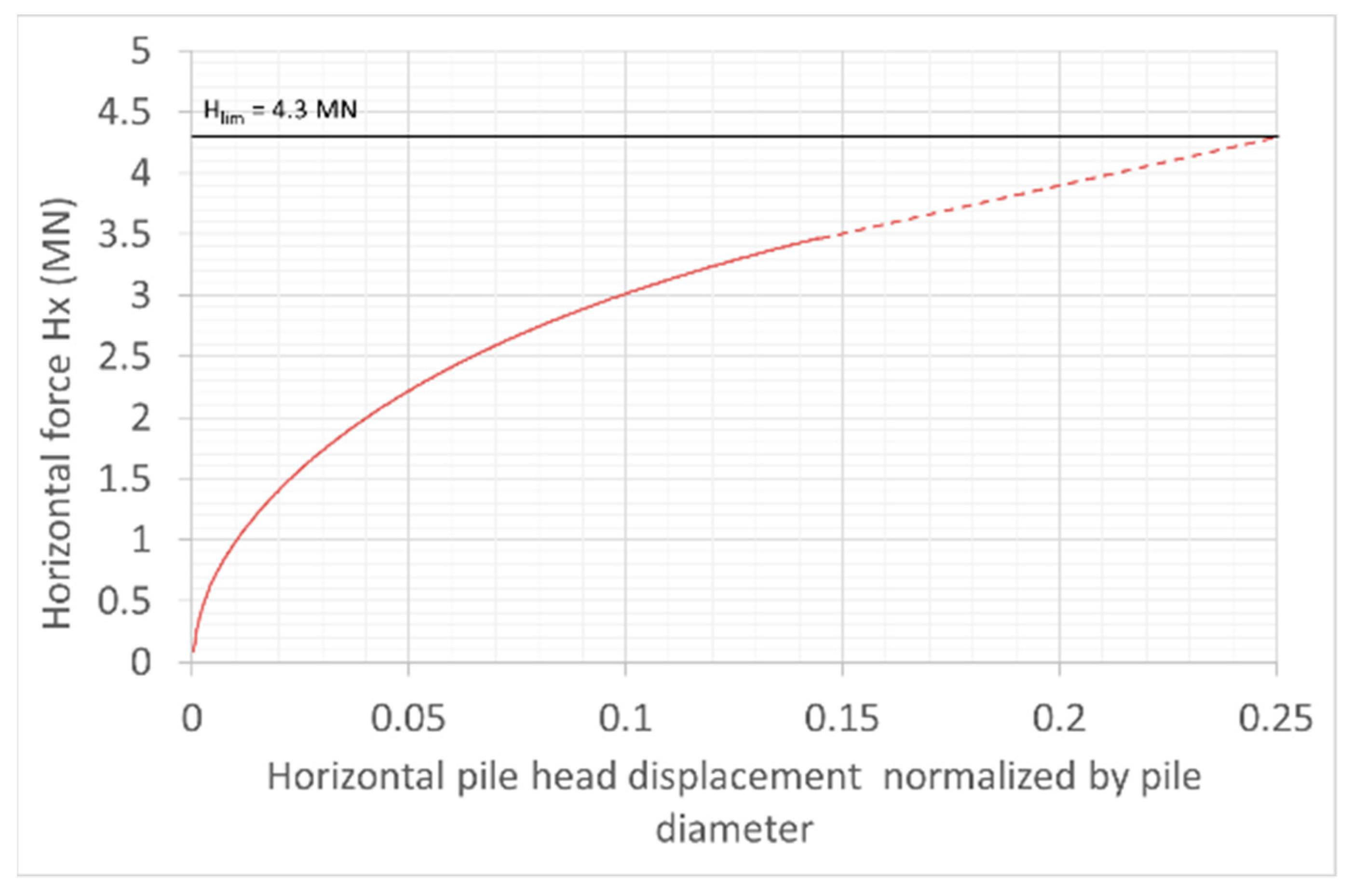
Hmax ratio (cf. Equation (3)) is equal to 0.147. Additionally, the ultimate lateral loading for the case study is numerically determined to equal
Hlim = 4.3 MN (see
Section 3.1) in order to compute the average force ratio (
Hm/Hlim) and cyclic amplitude ratio (
Hc/Hlim).
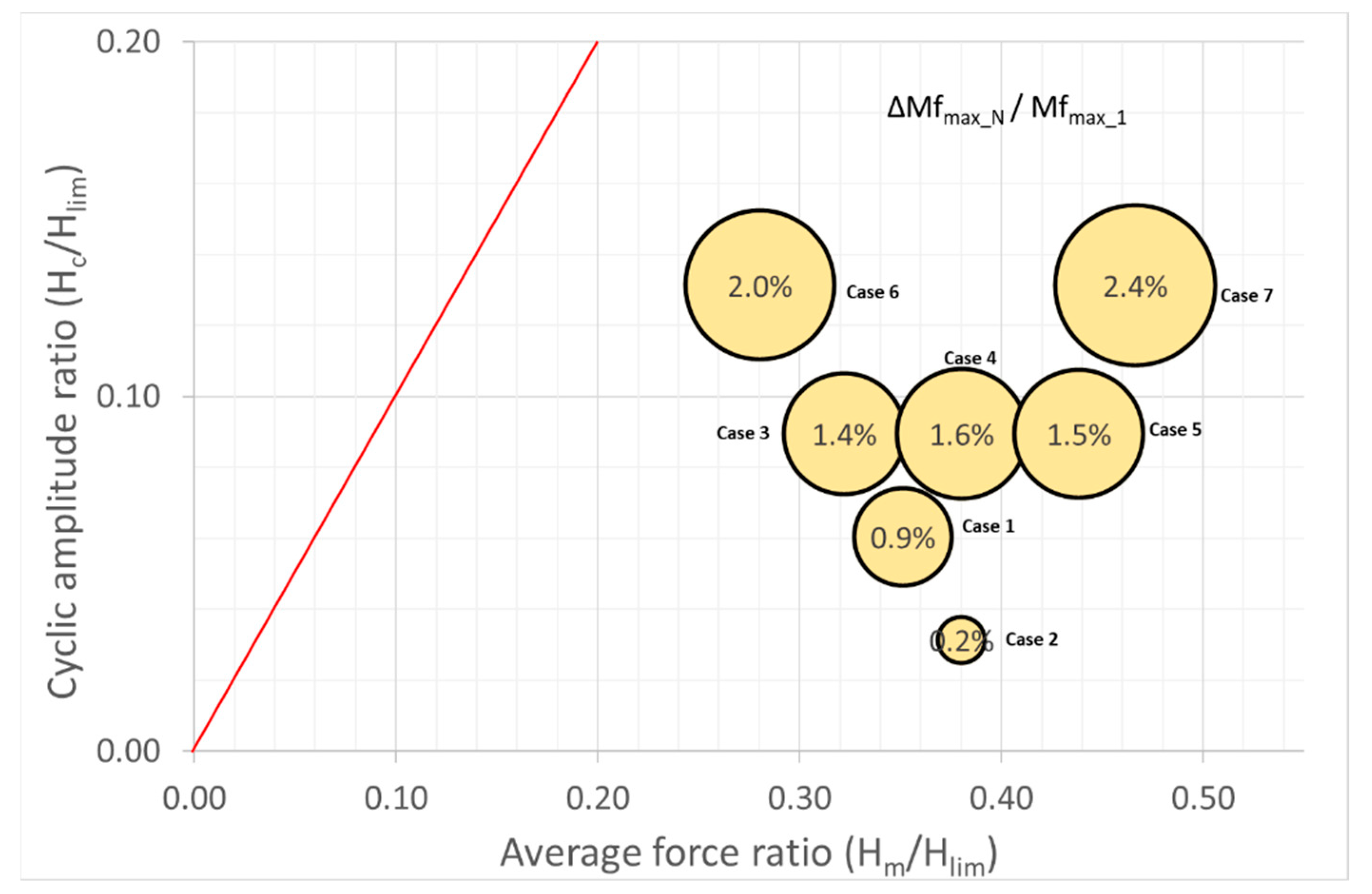
The numerical parametric study conducted is summarized in
Table 1 and
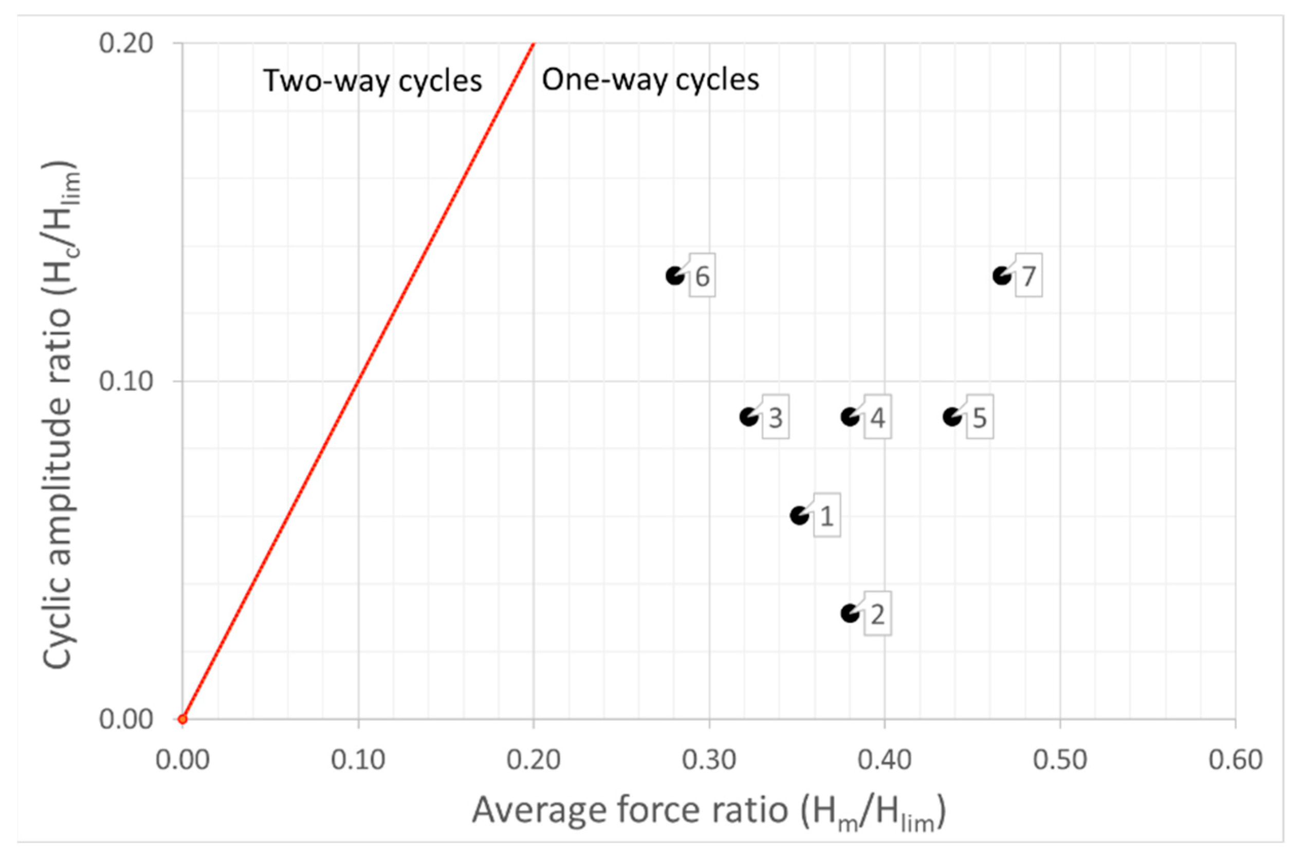
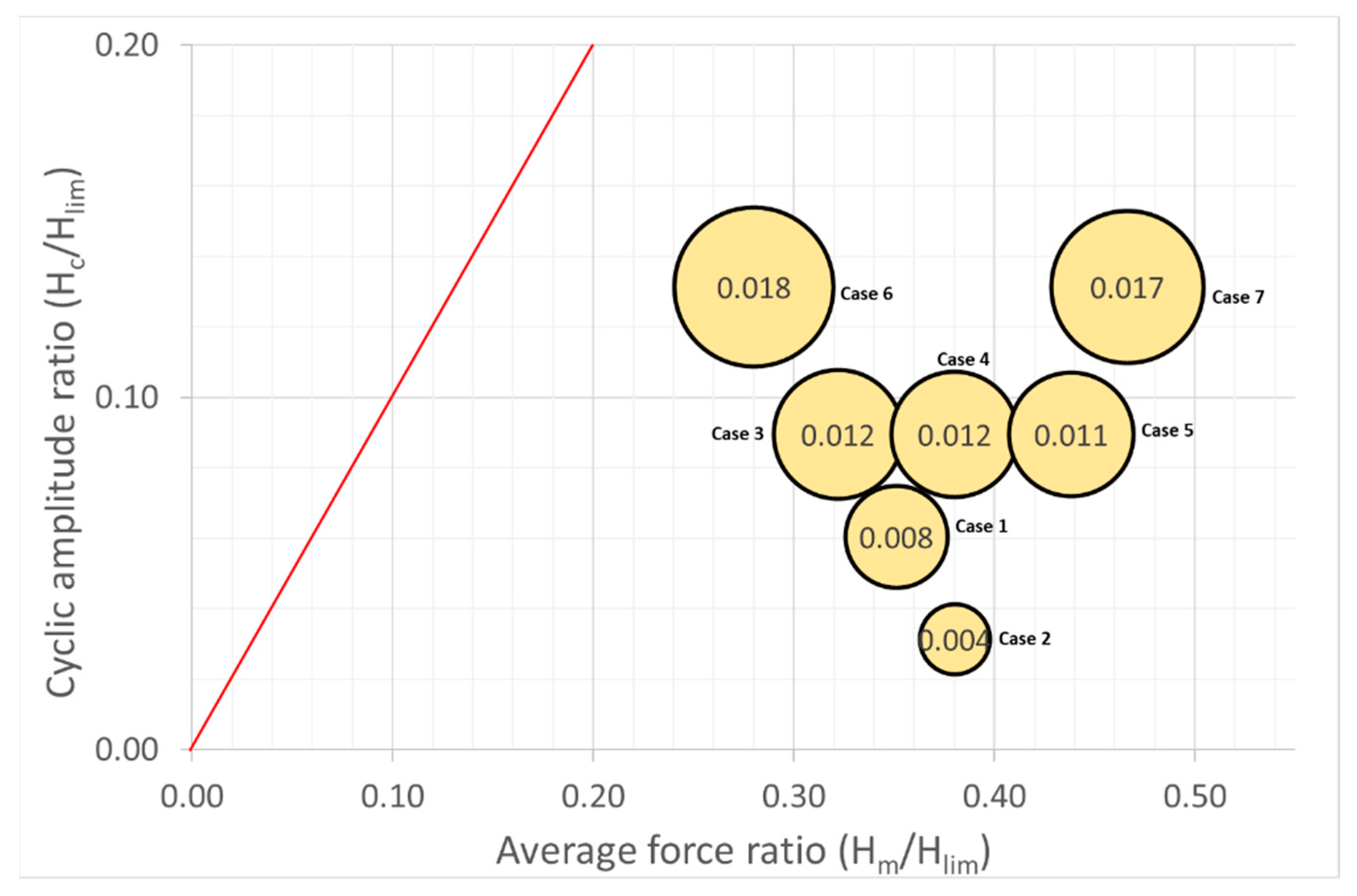
Figure 4. The reference case is “case 1”. Cases with a larger cyclic amplitude than the reference case were mainly investigated (cases 3–7), whereas case 2 is for a smaller amplitude. The effect of the average force value for a fixed amplitude can be explored by comparing cases 3, 4 and 5, and cases 6 and 7.
Figure 4 also highlights that only “one-way” cycles are applied (no load reversal).
The period of loading cycles is around 10 s. In the numerical model, no dynamic effect is thus considered—i.e., cyclic loading is applied under quasi-static conditions, and calculation will be performed under drained conditions, all the more that a sand stratum is envisaged.
The case of 1.7 m-diameter (D = 1.7 m) and 10 m-long pile (L = 10 m) founded in a dense homogeneous sand mass was examined. The pile is a hollow pile made of steel, with a wall thickness of 35 mm (internal diameter D
int = 1.63 m). With
Ep = 200 GPa and a pile quadratic moment
Ip = π/64 × (D
4–D
int4) = 0.0635 m
4, the flexural pile rigidity is
Ep × Ip = 1.27 × 10
10 N·m
2. The soil “stiffness” E
s is taken equal to 50 MPa. The value of R of Equation (1) is then R = 4.0 and the pile length is L = 10 m = 2.5 R. The pile length being between 1.48 and 4.44 R, this pile is therefore supposed to have a medium relative flexibility [
3].
Concerning the soil mass, a dense and homogenous layer of sand is considered. The main geotechnical characteristics that will be considered to calibrate the soil constitutive model for the numerical analysis are its submerged unit weight γ’ = 10.2 kN/m3; the maximum friction angle φ = 37°; the cohesion c = 0 kPa; the dilation angle Ψ = φ − 30 = 7; and a deformation modulus Es = 50 MPa.
2.2. Numerical Model
The issue addressed in this study is a typical soil–structure interaction problem. It is handled here by implementing a numerical method termed a “direct method”, since the soil mass and the structure elements are part of the same model, here in a continuum. The numerical model is developed with the commercial finite difference program FLAC3D (Fast Lagrangian Analysis of Continua) v. 5.01 [
22]. The code uses an explicit numerical scheme that solves the dynamic equations of motion, even for static problems, in conjunction with an incremental constitutive law over a small time step, at discrete points in space (grid-points). This method is particularly well adapted for analysing the non-linear behaviour of soils and soil–structure interactions. Because no matrices are formed, large three-dimensional calculations can be made without excessive memory requirements. Moreover, the internal programming language (FISH) and command-driven mode permit applying the desired loading path. This is a powerful feature when dealing with a complex multidirectional loading process, are addressed in this study.
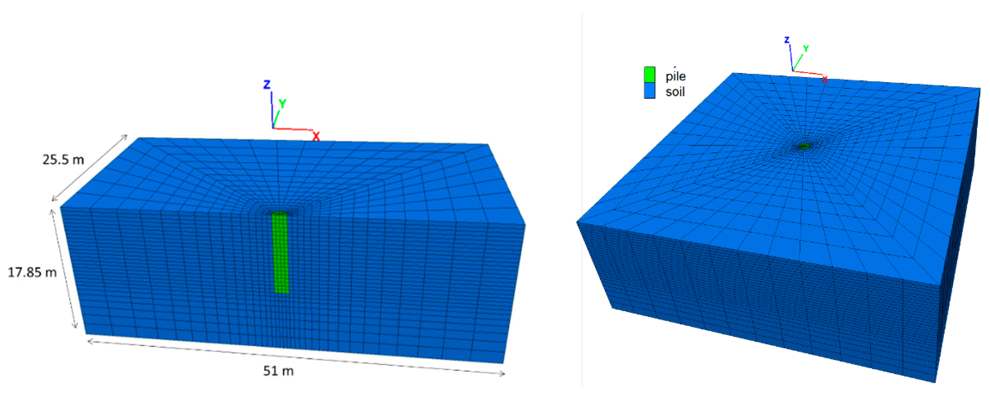
The numerical model in a continuum consists of a soil mass with boundary conditions in which a pile made of zone elements is embedded (
Figure 5). For the case of mono-directional horizontal loading of the pile, only half of the soil mass needs to be simulated due to symmetry condition (loading H is only applied in the x direction defined in
Figure 5) and in order to optimize the calculation duration. On the contrary, the multi-directional loading case requires the implementation of a full model. The boundary conditions consist of node fixity in the x direction for the vertical planes perpendicular to the x direction, in the y direction for the vertical planes perpendicular to the y direction (also valid for the symmetry plane in the case of the half model) and in all directions for the horizontal bottom plane. The global size of the model and the size of the zones (mesh refinement) were the subject of a preliminary parametric study performed by Obaei (2020) [
24]. The optimized models are depicted on
Figure 5. The mesh is finer near the pile, and the size of the zones regularly increases when radially moving away from the pile axis. The model width is equal to 30 D, which was sufficient to prevent any boundary effect under pile lateral loading. The model for mono-directional loading (half model) contains 11,472 zones (10,464 for the soil and 1008 for the pile) and 12,956 grid-points; the model for multi-directional loading (full model) contains 22,944 zones (20,928 for the soil and 2016 for the pile) and 24,847 grid-points. The total height of the model could be optimized as only horizontal loading is applied on the pile head, and it is here equal to 17.85 m, i.e., 7.85 m below the 10 m pile toe.
The pile is actually a hollow cylinder but in the present study it is simulated as a solid cylinder with an equivalent bending stiffness (E
p × I
p), for modelling simplification reasons. The pile is made of cylindrical zone elements. The quadratic moment for a solid cylinder of diameter D being I
p_eq = π/64 × D
4, the equivalent Young modulus for the solid pile, is equal to E
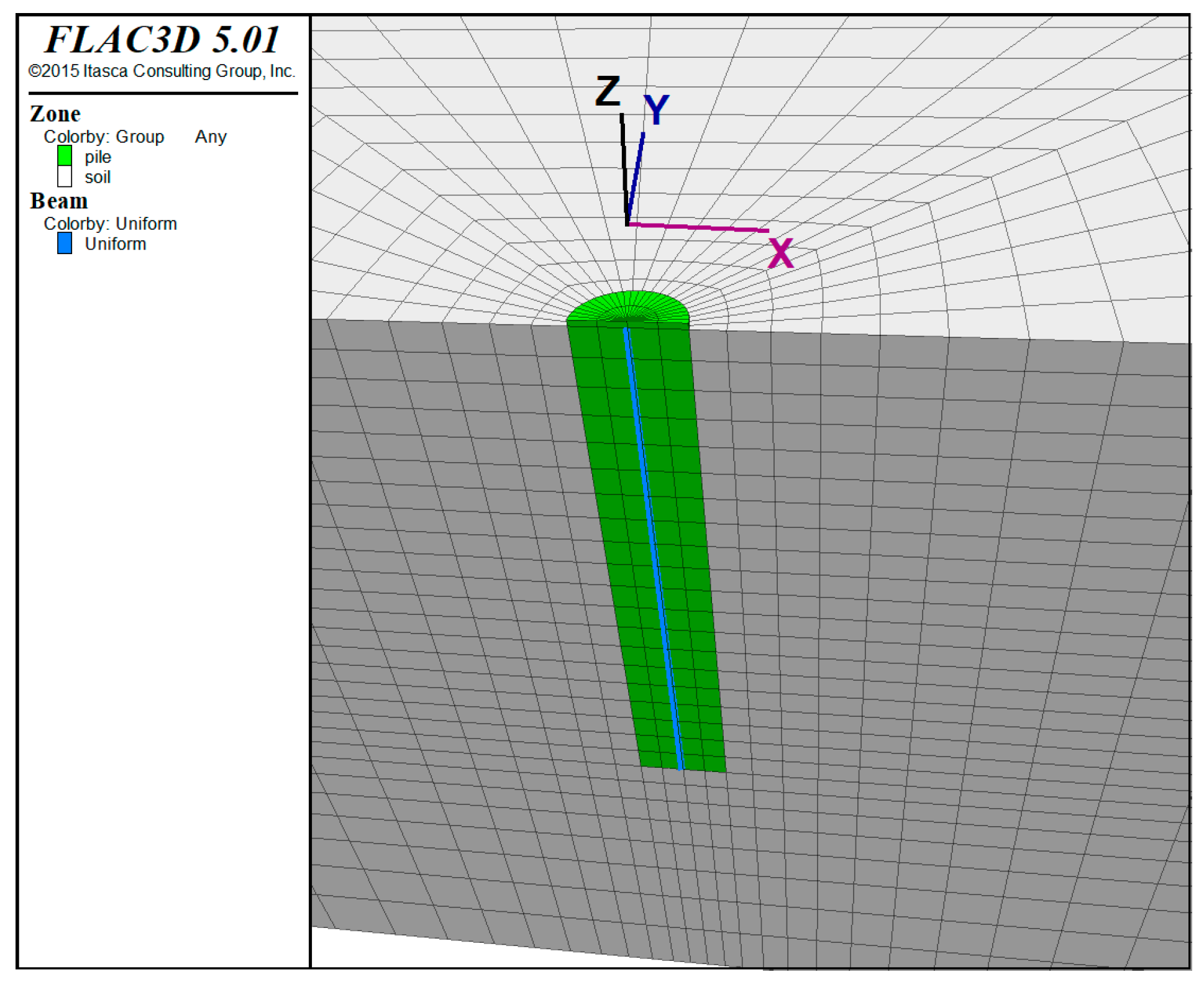
p_eq = 31 GPa. The 10 m-long pile is made of 20 slices of vertical zones plus an additional 0.1 m-thick element, above the soil surface, in order to apply the pile head loading, as depicted on
Figure 6. Moreover, in order to facilitate the analysis in terms of bending moments generated in the pile during the lateral loading, a vertical beam made of 20 structural elements is generated in the pile axis (
Figure 6). This beam has low E
b and I
b characteristics (compared to E
p and I
p values), in order not to affect the pile bending stiffness, but has the same deflection as the pile. According to the Bernoulli beam theory, the pile bending moment M
p is then equal to M
b × (E
p × I
p)/(E
b × I
b), where M
b is the bending moment directly recorded in the numerical model using the beam element. Interfaces are generated between the pile and the soil (at the pile shaft and toe).
2.3. Constitutive Models
When dealing with a soil–structure interaction problem using numerical modelling in a continuum, the choices of material and interface constitutive models and the calibration of their parameter are essential.
As already discussed, the pile–soil interaction behaviour is highly influenced by the rigidity of the pile, characterized by (Ep × Ip) value. The pile is simulated by volume element with an elastic behaviour and an equivalent Young modulus equal to 31 GPa. The Poisson’s ratio is taken equal to 0.3.
Concerning the modelling of the soil behaviour, to overcome the limitations of the classical elastic–perfectly plastic model with Mohr–Coulomb failure criteria, a friction hardening elastoplastic model, with shear-induced volumetric changes and stress-dependent stiffness, was implemented is this study. The Flac3D built-in “CHsoil” model was used [
25]. This model permits to account for a higher soil stiffness during unloading–reloading process and for a soil stiffness dependent on the initial stress state. Indeed, the initial stress state significantly increases from the head of the pile, at the mudline, to the toe at 10 m depth, actually leading to variation in soil stiffness along the pile. To calibrate the soil model elastic stiffness parameters, an average value of a deformation modulus equal to 50 MPa and Poisson’s ratio equal to 0.2 (i.e., a bulk modulus
Kref = 27.8 MPa and shear modulus
Gref = 20.8 MPa) are targeted at a mid-depth of 5 m, where the initial mean effective pressure is equal to
p’m = 30 kPa, also set as the reference pressure
pref. In CHsoil model, the elastic bulk and shear modulus are then computed using Equations (7) and (8) according to the initial mean effective pressure
p’m, which increases with depth due to soil weight. With m = n = 0.5, at a depth 10 m, the elastic deformation modulus is equal to 70 MPa:
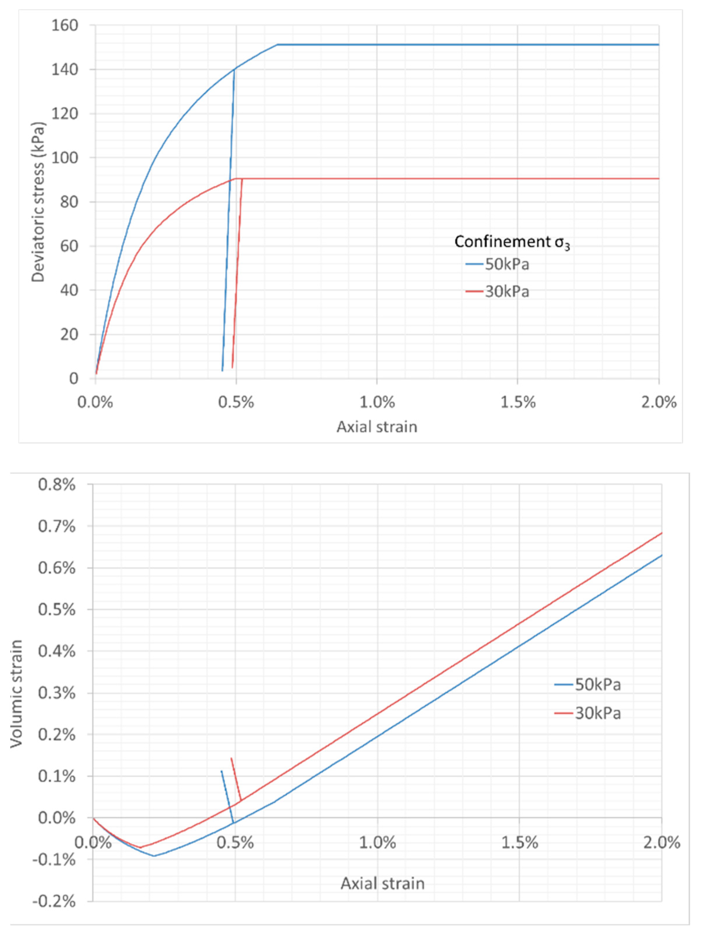
The CHsoil model parameters used in this study are given in
Table 2 and the corresponding behaviour obtained on triaxial compression tests at 30 and 50 kPa of confinement are depicted on
Figure 7, with an unloading–reloading loop.
However, this model is not able to account for specific features of sand behaviour under a high number of load cycles (strain accumulation due to fatigue, etc.), as there is only an isotropic shear hardening mechanism. Indeed, as this numerical study first aims at developing a complex loading procedure (multi-directional cyclic lateral loading), the efforts were not concentrated on implementing a constitutive model with a high degree of complexity, and this aspect is part of the numerical work perspectives.
Interfaces are placed between the soil and the pile by using the standard interface feature from the software. The interfaces are characterized by normal and shear stiffness and sliding properties. The interface normal stiffness k
n and shear stiffness k
s are computed equal to 1.2 GPa/m, according to the adjacent zone size and stiffness, in order to optimize the computational time [
22], so they have no real physical meaning. The interfaces have no cohesion and a friction angle equal to 2/3 of the soil ultimate friction angle, i.e., equal to 2/3 × 37° = 24.7°, which is a conventional friction angle for a relatively rough soil–steel interface.
2.4. General Modelling Procedure
A lateral pile loading simulation follows the subsequent steps:
(1) Mesh generation for the ground mass, the pile and the interfaces. The pile is first generated separately above the soil mass, and is then moved down into its final position, in order to correctly create the contact with the interfaces [
22]. The pile is thus numerically wished-in-place and the possible pile installation effects are therefore not represented. Moreover, this procedure would correspond to the case of a close-ended rather than an open-ended pile.
(2) Stepping until reaching static equilibrium under gravity and soil self-weight. The zones occupied by the future pile are first considered as soil. The calculation is performed under drained conditions, so the submerged unit weight γ’ = 10.2 kN/m3 is assigned to the zones and an earth coefficient K0 = 0.5 is used to initialize the horizontal effective stress. Static equilibrium is considered reached when the unbalanced force ratio is below 10−6. This ratio is defined as the largest ratio between the maximum grid-point unbalanced force to the average applied force amongst all of the model grid-points.
(3) The pile zones are assigned pile properties and a new static equilibrium is reached.
(4) The displacements are initialized (at this stage, they are very small and have no physical meaning).
(5) Lateral loading is applied using the procedure described below.
(6) All the calculations are performed in small strain conditions.
2.5. Loading Procedure
Due to the formulation of the program Flac3D, a loading can be defined by applying a velocity to model grid-points. This procedure is especially appropriate as the loading (and loading direction) varies during the process. The applied velocity then corresponds to an increment in displacement (in the same direction) at each time-step (of duration Δt) of the stepping process. In the case of a quasi-static study, the velocity has only a numerical signification, and should be sufficiently small in order to keep the model in a quasi-static equilibrium (i.e., with a negligible unbalanced force ratio). The choice of the applied velocity is discussed later. Moreover, numerical damping is introduced in the computational process to reach a quasi-static equilibrium state (combined damping is used in this study).
To apply a horizontal force at the head of the pile, a horizontal velocity is therefore applied to all pile head grid-points (on the 0.1 m thick pile slice above the mudline). Nevertheless, the process is governed in terms of force value, by implementing adequate servo files that compute the current resulting force at pile head during the process and then adapts the required velocity accordingly (in particular, its direction). The current force at the pile head is computed as the sum of the unbalanced forces of all the grid-points of the pile head where the velocity is applied (in the x direction to obtain the force in x direction Hx and in the y direction to compute Hy, where applicable, i.e., for the multi-directional loading case).
Two types of loading procedures are implemented: for mono-directional lateral loading (only in the x direction) and multi-directional lateral loading (in x and y directions).
2.5.1. Loading Procedure for Mono-Directional Monotonic Loading and Cyclic Loading
A velocity is applied on the pile head only in x- direction, and due to geometrical and material symmetry of the model, it induces a pile head horizontal force in the x direction. The impact of the numerical value of the velocity on the model response was the subject of a parametric study [
24] and a value equal to 5 · 10
−8 (m/step) permitted to maintain an acceptable quasi-static equilibrium during the loading process (i.e., negligible maximum unbalanced force), with a reasonable computational time. Horizontal loading is accomplished with a positive velocity in the x direction (pile head displacement in positive x direction, see axes in
Figure 5 and
Figure 6), until the desired H
max value; then, unloading is performed by applying a velocity in the opposite direction (-x) until the desired H
min value. The velocity was set to 1 · 10
−8 (m/step). Reloading and unloading loops are applied in the same manner. Twenty cycles were applied for each calculation (under mono-directional loading, system behaviour was considered unaffected after around 20 cycles, see
Section 3).
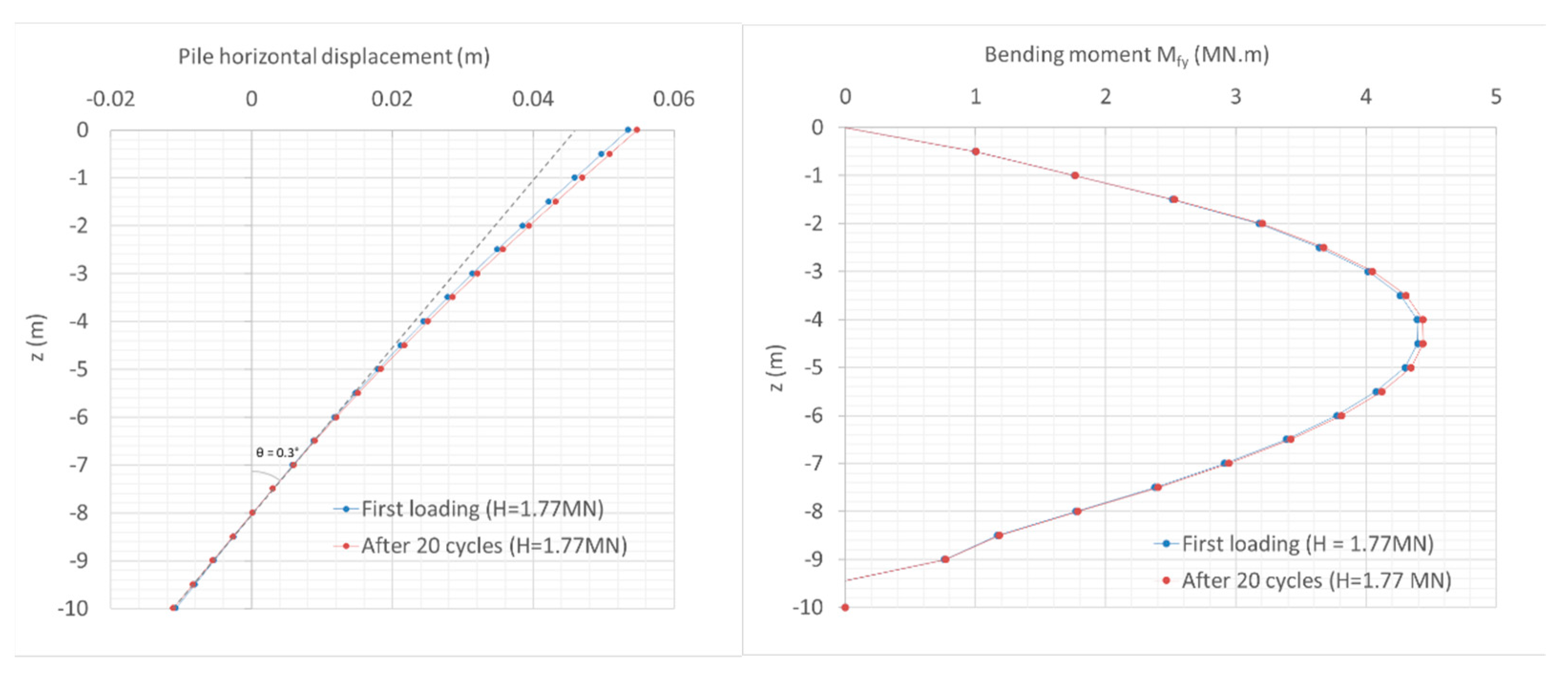
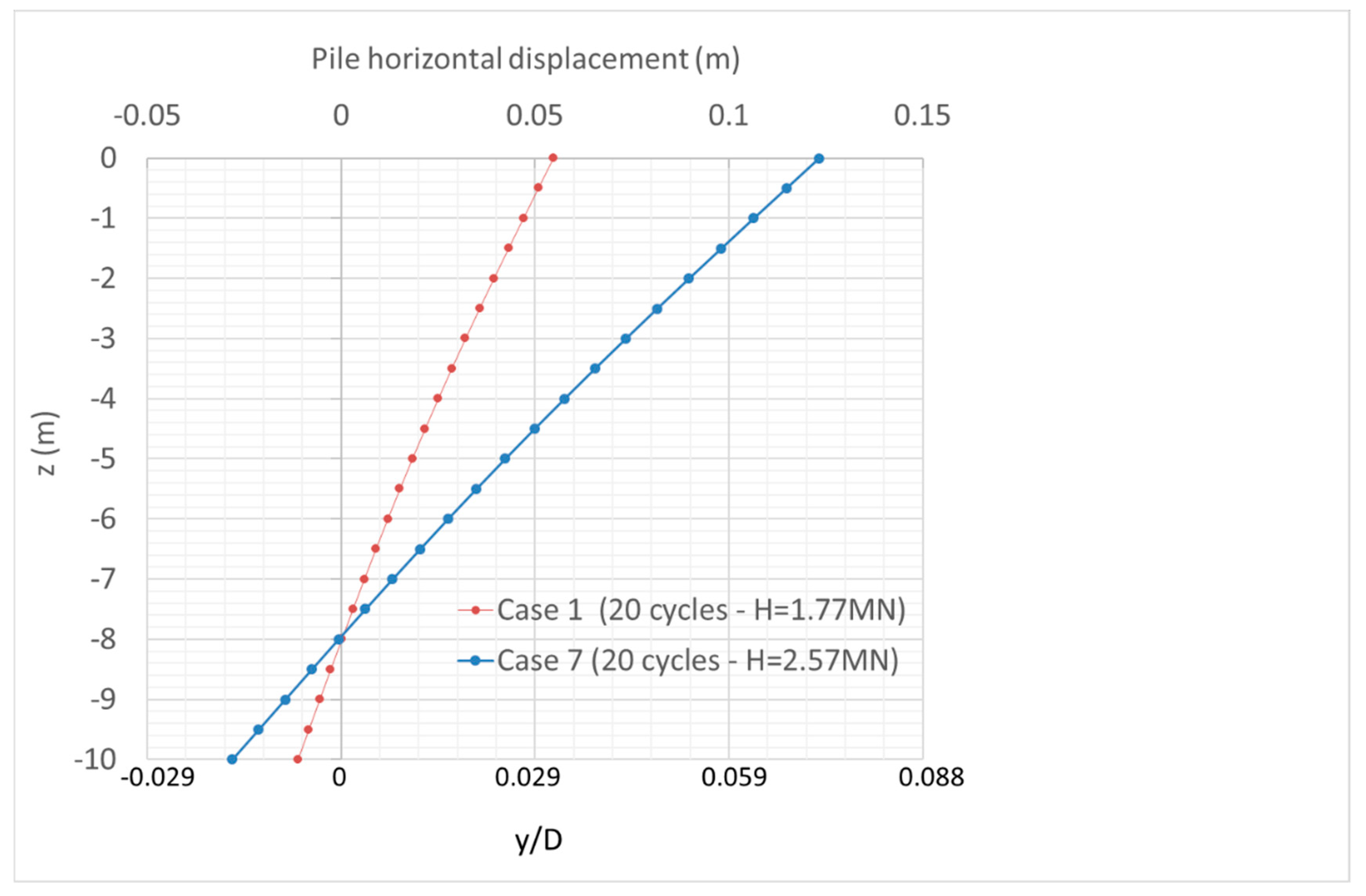
Under lateral monotonic loading, with a PC (CPU 1.9 GHz–RAM 16 Go), the computation duration was approximately 2 h to reach H = 1.77 MN and 9 more hours were needed to reach a pile head displacement equal to 0.15 D (H = 3.46 MN), on the half model. The computation time is directly proportional to the applied velocity value. Concerning the cyclic loading, achieving 20 loops of unloading–reloading took about 20 h for case 1 and 48 h for case 7 (as the computation time is directly correlated to the pile head displacement, for a given applied velocity).
2.5.2. Loading Procedure for Multi-Directional Cyclic Loading
Concerning a multi-directional horizontal loading process as described in
Section 2.1, a specific procedure has been developed in the frame of this work, in order to apply a given loading path, but controlled in terms of displacements. Indeed, the complexity lies in the fact that force vectors and displacement vectors increments are not co-linear.
The first loading is applied using the mono-directional procedure (but on the full model), until Hmax value is reached at pile head.
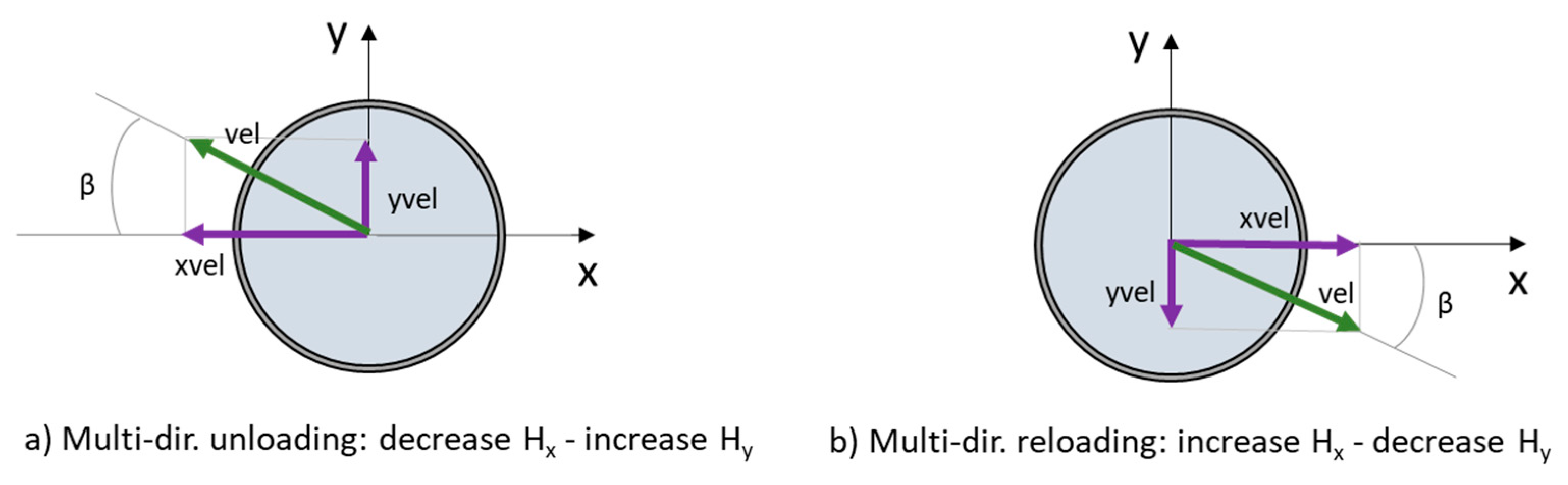
Concerning the unloading, the resulting horizontal value H is considered varying linearly according to the azimuth ω (
Figure 3) from H
max down to H
min, for ω = 0 to ω
max = 30°. The horizontal force H has two components: H
x = H cosω and H
y = H sinω, as shown on
Figure 8 and
Figure 9a) depicts the imposed velocity for unloading (xvel negative to decrease H
x and yvel positive to increase H
y). The absolute value of the norm of the velocity vector is kept constant (vel = 5 × 10
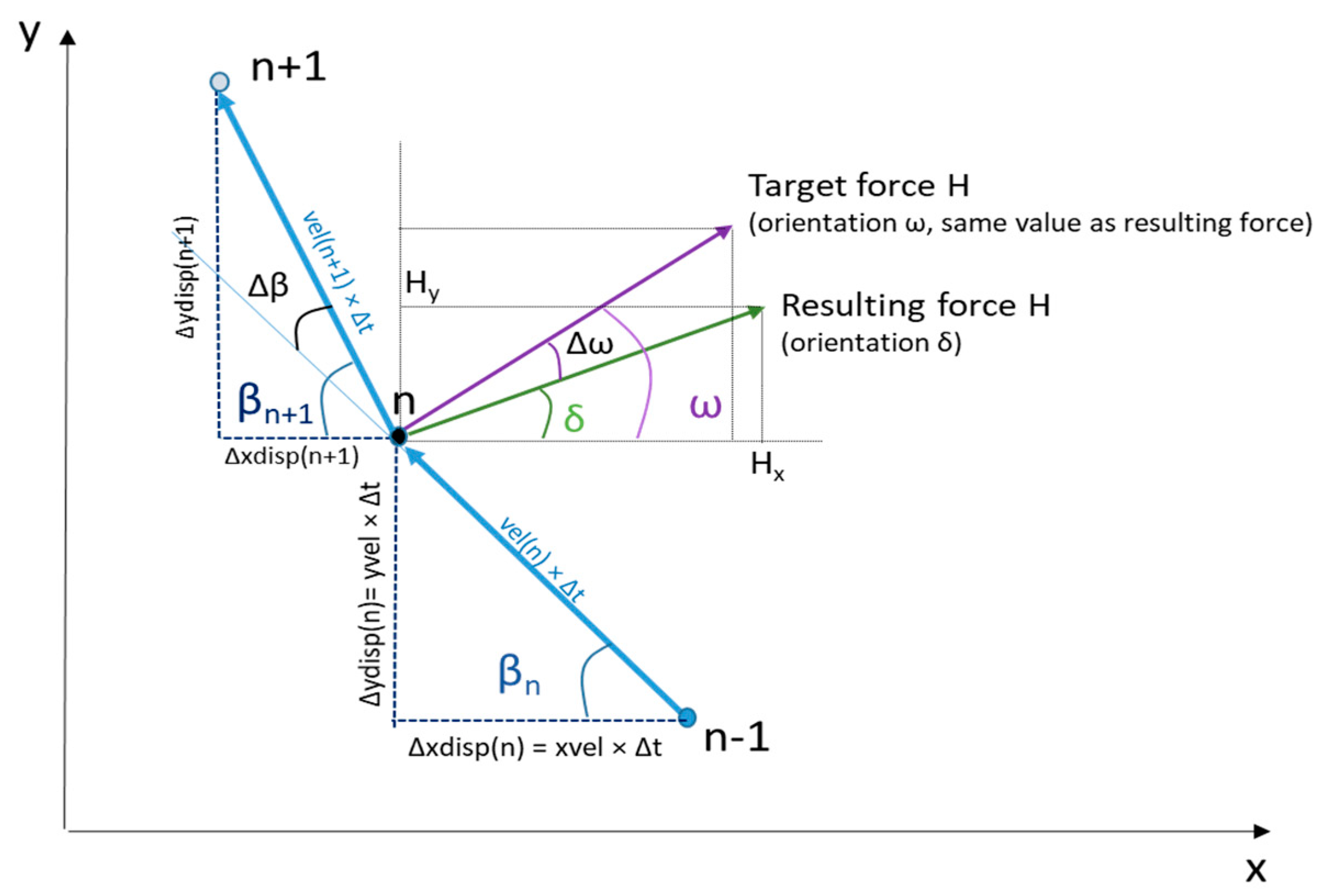
−8 m/steps as a cruise value, after a ramp of increase) but the orientation (angle β) of the velocity vector is adjusted during the calculation, in order to follow the imposed path in terms of force H = f(ω). The initial value for β is arbitrarily picked at 45° and the x and y component of the velocity (xvel and yvel) are re-calculated based on current β value at each step (xvel = vel × cos β, yvel = vel × sin β). On
Figure 10, the angle δ is defined as the azimuth of the resulting horizontal force at the current step (step n), whereas the targeted azimuth is ω (computed according to the current H value and given function H = f(ω)). The difference is Δω = ω − δ. For the next step (n + 1), the orientation of velocity is then adjusted to correct the orientation of the force. The new value of β is computed with β
n+1 = β
n + Δβ, with Δβ = Δω. During the whole process, the adjusting angle Δβ = Δω actually oscillates around zero. The unloading process stops when the horizontal force H reaches H
min.
The same concept is implemented for reloading, by inverting the sign of xvel and yvel (
Figure 9b) and with Δβ = −Δω. The norm of velocity vector is also equal to 5 × 10
−8 m/steps as a cruise value, after a ramp of increase. The reloading process stops when the horizontal force H reaches H
max; then a new unloading–reloading loop is achieved. This cyclic process is applied for 40 loops (compared to the mono-directional loading, 20 additional cycles had to be applied to confirm the trend observed after approximately the ten first cycles (see Results Section).
The computation of the first 20 cycles took about 6.5 days with the same PC.
4. Discussion
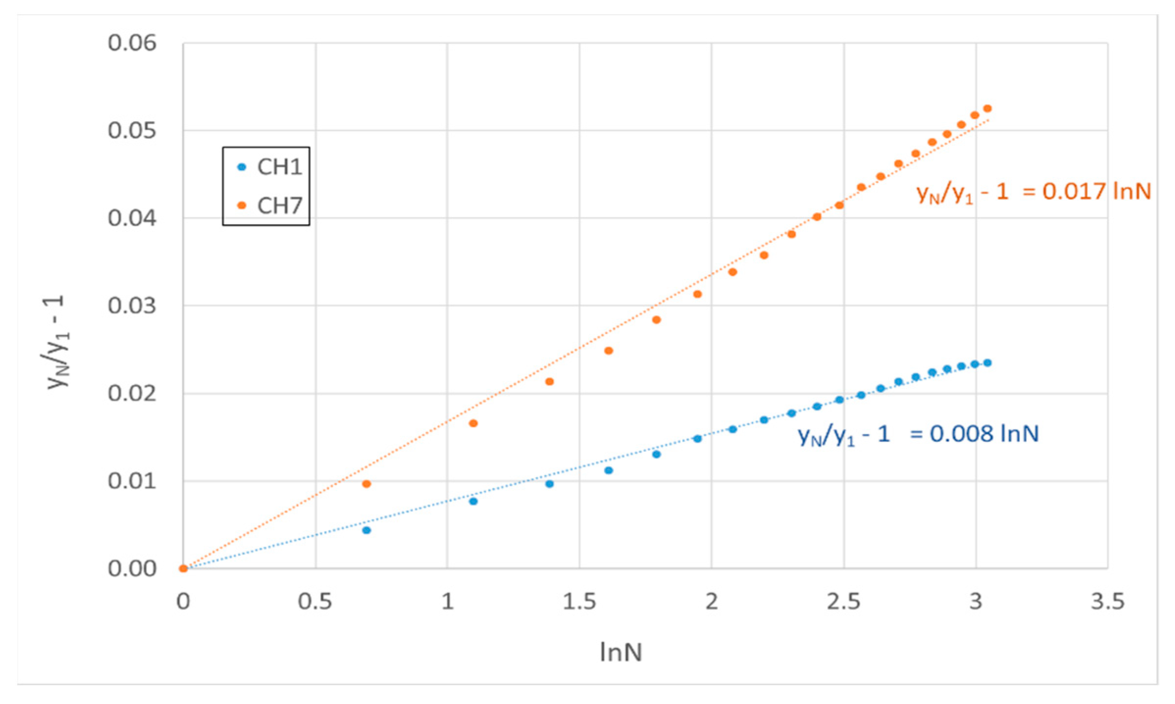
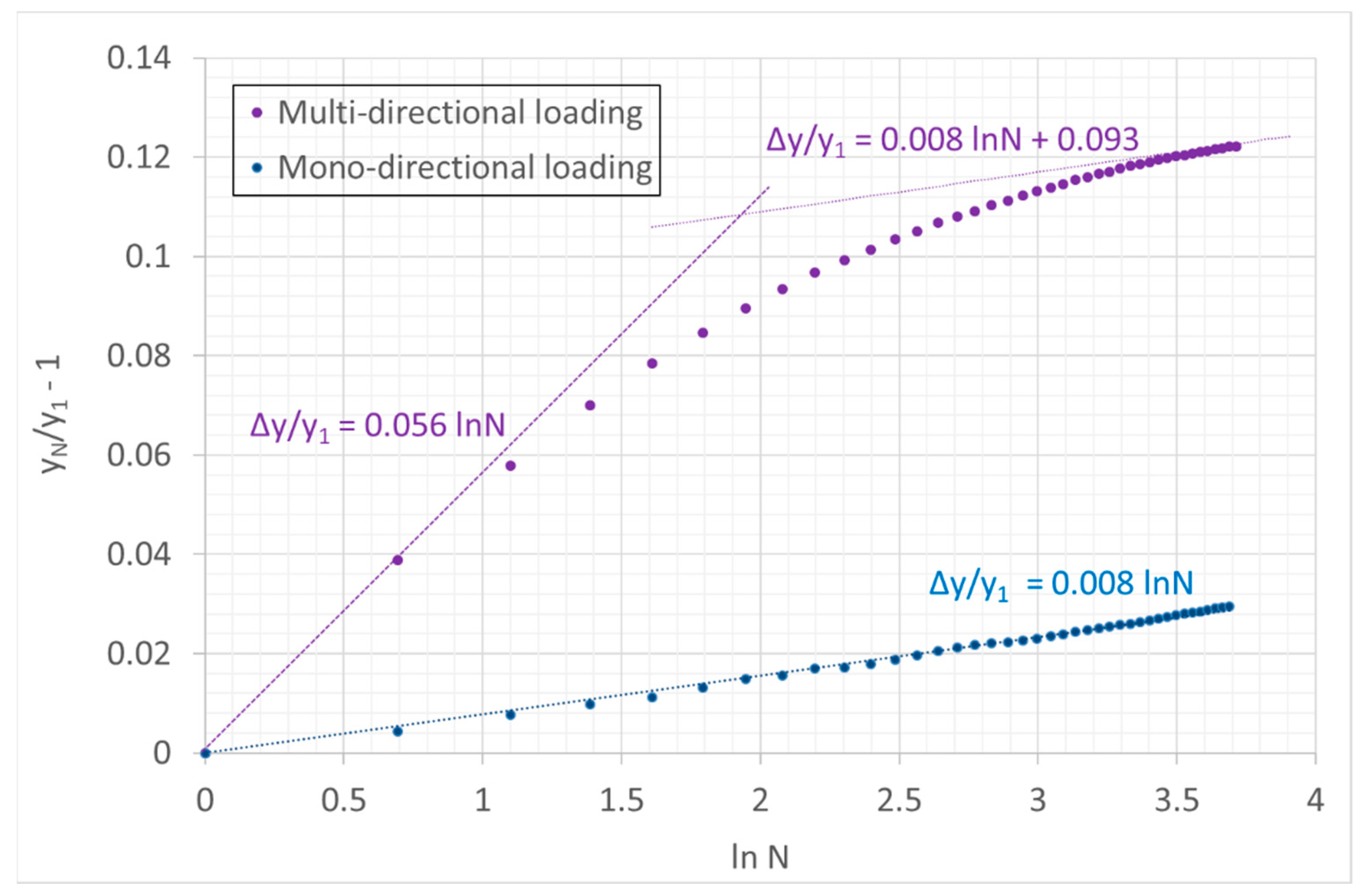
The numerical results obtained on the mono-directional lateral cyclic loading are in qualitative good agreement with the predictive logarithmic law for the additional pile head displacement (Equations (2) and (3)). The parameter α from the Lin and Lao (1999) [
12] law: y
N/y
1 − 1 = α lnN could be obtained and varied between 0.004 and 0.018 mainly according to the cyclic amplitude H
c for the investigated cases, but, in all likelihood, not according to H
m.
The logarithmic law proposed in the SolCyP recommendation [
11] would lead to the expression of the parameter α (from Equations (2) and (3)):
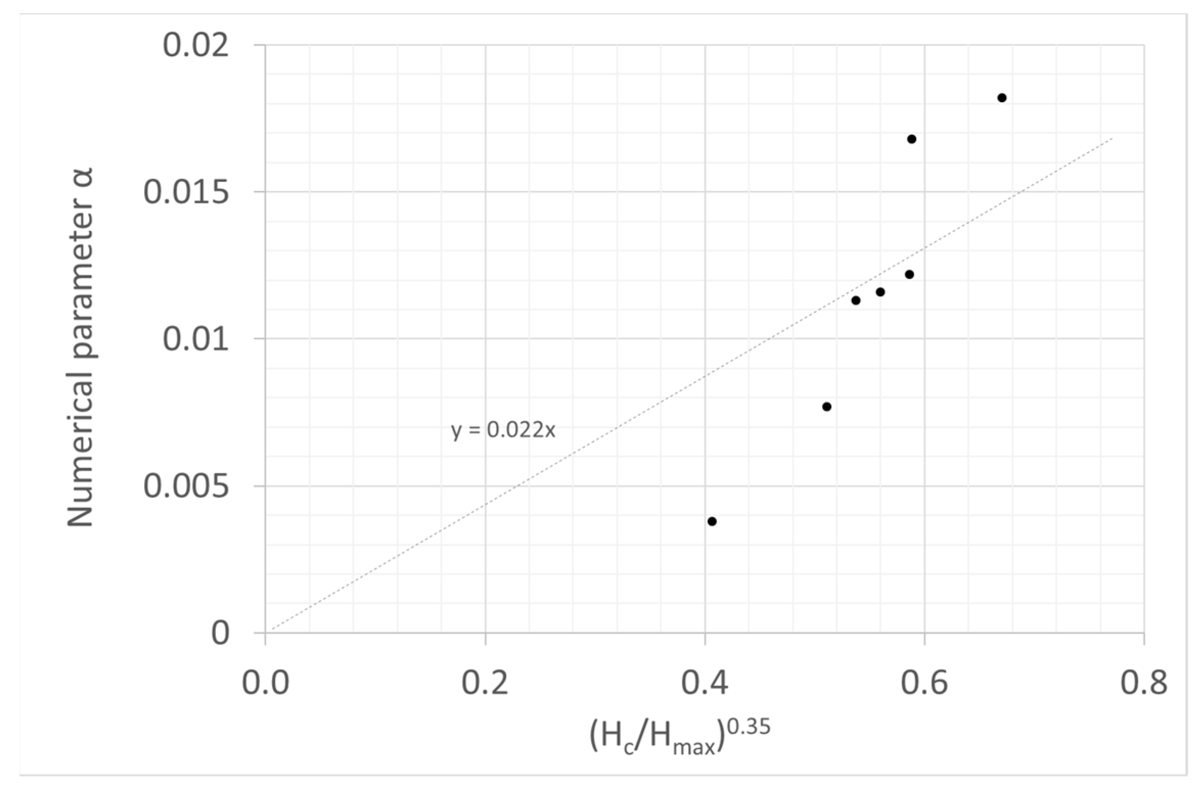
Thereby,
Figure 23 depicts the evolution of α obtained from the numerical results, according to (H
c/H
max)
0.35, that should lead to a linear relation with a slope 0.102/CR if Equation (9) is satisfied, with the assumption that the rigidity coefficient CR (defined in Equation (4)) is independent on the loading. The trend of α increasing with (H
c/H
max)
0.35 is observed, but the linear relation does not accurately apply. A value of 0.102/CR = 0.02 (that satisfies the numerical cases 3, 4 and 5), would lead to CR = 5.1. However, the rule given by [
3] (Equation (1)) with a soil stiffness E
s = 50 MPa, leads to a flexible pile for E
p I
p below 1290 MN·m
2 (=(E
pI
p)
fl), then to CR = 1.6. According to Equation (9), the parameter α would vary between 0.026 for case 2 and 0.043 for case 6. These values are thus 2–6 times higher than the values obtained with the current numerical modelling.
The trends given by the proposed numerical model are thus qualitatively acceptable, but it seems that it underestimates the pile head displacement accumulation under lateral mono-directional cyclic loading. This is probably due to the implemented constitutive model for the soil that is not able to take accurately into account the strain accumulation in the soil under repeated loading, and this is a major numerical work perspective to this current study. In fact, the elastoplastic model implemented in this study has only an isotropic hardening shear mechanism, with an elastic response on an unload–reload loop on a triaxial test path (
Figure 7), thereby initially not able to take ratcheting effect into account [
26]. However, in this soil–structure interaction system, the stress path is more complex than on a pure axisymmetric triaxial test path, leading to stress redistribution in the surrounding soil, to additional plastic zones at following cycles and thus to additional deformations.
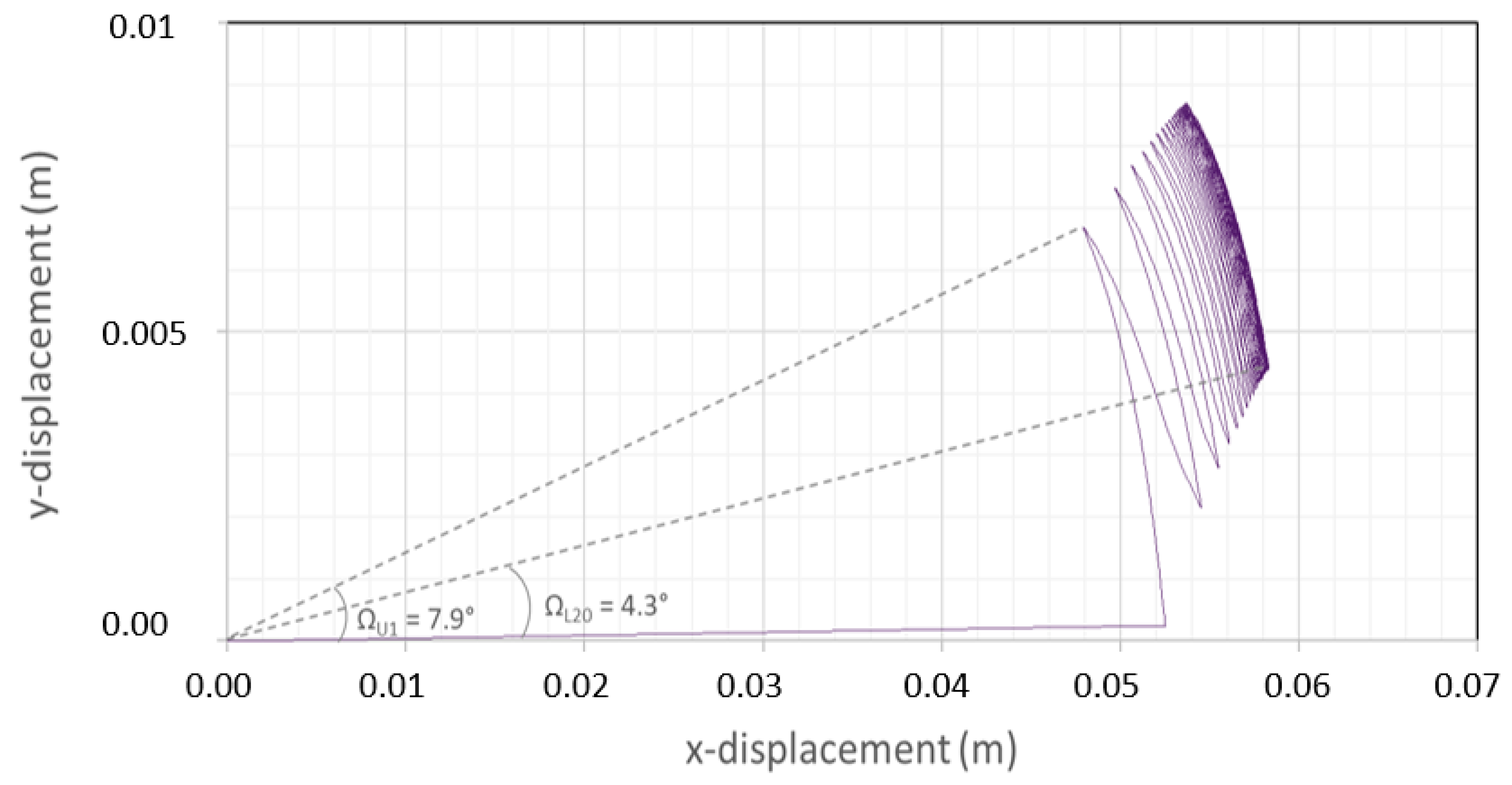
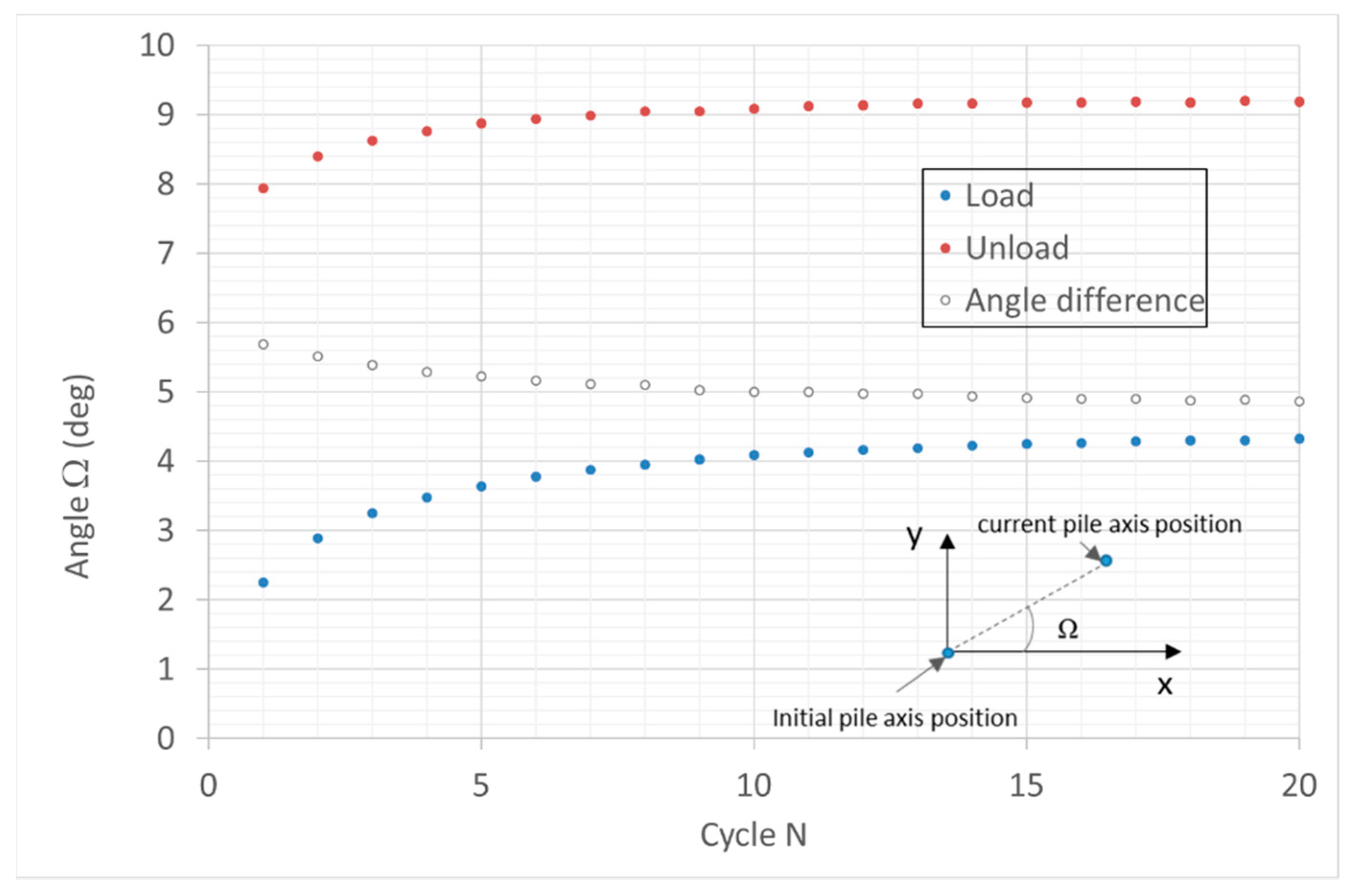
As this numerical model accurately represents the qualitative pile–soil interaction behaviour under mono-directional lateral cyclic load, it is implemented to explore the behaviour under multi-directional lateral cyclic loading. This latter requires the implementation of a specific loading procedure. This was successfully done and the numerical model conducted to highlight interesting and encouraging aspects of the specific behaviour under a lateral load that varies in its direction during the cyclic process. The main observations are:
- —
As expected, the pile head displacement suffers a displacement accumulation in both horizontal directions during the cycles, leading to a misalignment of the loading and pile displacement directions;
- —
The pile head displacements are greatly increased compared to the mono-directional cyclic loading with the same average and cyclic amplitude values. New plastic zones can develop throughout the cyclic loading process as additional deviated displacements go along;
- —
The pile head displacement does not follow a logarithmic law anymore. The rate of displacement accumulation decreases after about ten cycles, to reach a rate of accumulation similar to the one obtained on the mono-directional loading;
Nonetheless, the effect of the constitutive model on these numerical findings still needs to be highlighted.
In this study, a limited number of cycles of load were applied, as they were all simulated one after the other (cycle-by-cycle simulation). To investigate the behaviour under higher cycle numbers (hundreds, thousands or more), particularly an appropriate constitutive model should be used, but for cycle-by-cycle simulation, as this would lead to a numerical drift of the result along a high number of cycles (accumulation of numerical inaccuracies), as well as a high computational time demand. An alternative approach could be by using a Miner type law [
27] or a strain accumulation model [
28], that accounts for the accumulation of strains as a function of the number of cycles, relative density and load characteristics. Nevertheless, the applicability to multi-directional cyclic loading still needs to be demonstrated and calibrated for this type of model. The “cycle-by-cycle” numerical approach thus still has a useful future in order to highlight the mechanisms taking place in the system under such a complex loading path.
Moreover, this numerical approach could be extended to a parametric study on the pile bending stiffness (stiffer or more flexible piles compared to surrounding soil), to other loading conditions in terms of average and cyclic amplitude, but also by varying the load history, as it seems to be of high impact on the pile behaviour [
26].


