1. Introduction
Cyber–physical systems (CPS) utilize a variety of networks, hardware, and software components to control, interact with, or influence a physical process in the real world. Adversaries may attempt to affect those physical processes via attacking or exploiting the cyber component of CPS. Therefore, securing these systems against adversarial actions becomes a critical step to ensuring system integrity, functionality, and safety.
Generally, security for CPS refers to the application of defensive and resilience measures implemented to help sustain acceptable levels of operation in the face of adversarial actions. More specifically, defensive measures are the steps taken to prevent an adversary from disrupting, terminating, or taking over control of the operation of a system. Resilience, on the other hand, refers to the actions taken to ensure the continuity of the system’s expected service in spite of adversarial actions. Methodologies and techniques for achieving enhanced system security in the cyber domain are prevalent and well-researched, and have been applied to CPS as well. However, the methods and techniques used for enhancing the security of strictly cyber systems are not sufficient for CPS due to their lack of focus and inability to account for the physical interactions inherent to CPS and the system’s usage in a broader mission. There have been several recent efforts to characterize the relationship between cyber attacks and (potentially catastrophic) physical system behavior, for example [
1,
2].
In addition, it is challenging to address security early in the design process (and then to continue during the lifecycle as both the systems and threats evolve). Security needs and solutions are developed based on the perceived threats to the system and potential vulnerabilities identified in the system’s design. Often, this means that vulnerabilities are only discovered after a security breach [
3,
4] or after detrimental effects have already occurred [
5]. Of course, it is impossible to discover all potential vulnerabilities, and systems must be routinely updated and adapted as new threats emerge; however, new trends call for integrating security into all parts of the system’s lifecycle, including the pre-design and design phases. As
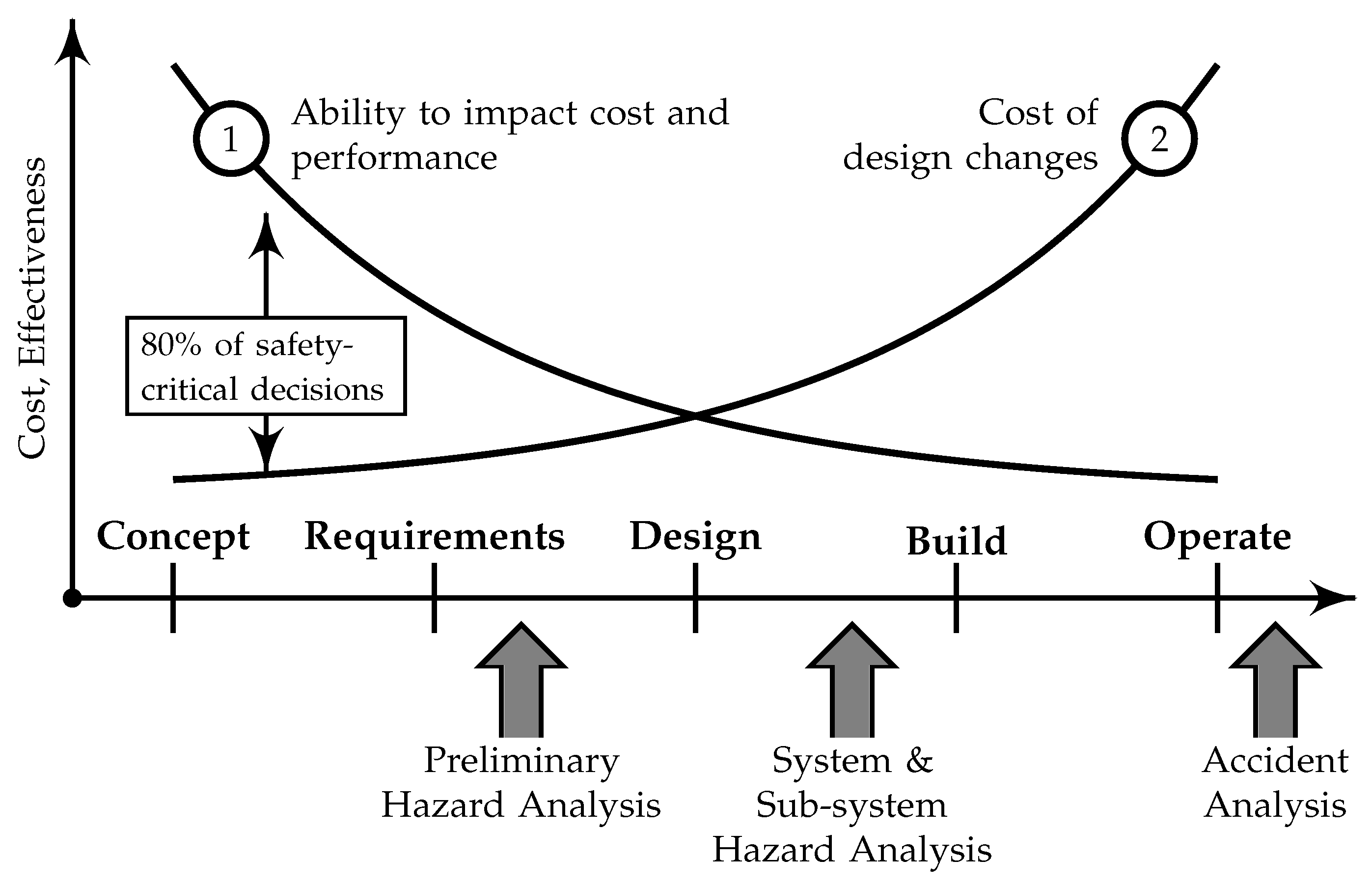
Figure 1 illustrates, research shows that efforts and decisions made in the early parts of a system’s life cycle have both decreased costs due to design changes as well as increased ability to impact the performance of a system [
6,
7,
8]. It is logical that cybersecurity efforts would follow a similar pattern and it therefore becomes advantageous to address security from the beginning of the system development and design cycle.
There are several challenges that we perceive in the preliminary design phase with respect to security of CPS. There are potentially many important stakeholders with many different (valid) perspectives and knowledge bases. How does one use these stakeholders, and how are they organized? What should be done in terms of methodology, technology, and/or tools that can be used to make the process more scaleable, traceable, and potentially repeatable? One thing that is clear is that there is not a single disciplinary collection that is capable of doing everything in terms of knowing how the system should behave, assessing the vulnerabilities or possible attacks to the system, or bringing to bear the operational characteristics in its intended environment(s).
The goals of such a methodology mirrors the needs of safety-critical systems. Particularly within the aerospace industry, designing in safety from the beginning of a system’s life cycle has been standard operating procedure for decades. In CPS, security is intertwined with safety due to inherent computer-controlled physical interaction with the real world. In some cases, design features or operating procedures intended to increase safety result in secure architectures. Consequently, it makes sense to draw upon these methodologies created to generate safe systems for the purpose of creating secure designs. In particular, the systems-theoretic models and analysis tools developed by Leveson, such as the systems theoretic accident model and process (STAMP) [
9] and systems theoretic process analysis (STPA) [
10], show promise in aiding the generation of requirements and understanding the behavior of CPS with respect to safety and security. Furthermore, a system in the preliminary stages of design will not have yet specific hardware and software components defined. A control-theoretic approach to defining the system behavior enables analysis while being agnostic to specific hardware and software implementations.
This paper presents a novel approach called the cyber security requirements methodology (CSRM), and an underlying theoretical framework and associated tools to support CSRM. The CSRM is a methodology to develop cyber security requirements during the preliminary design phase for CPS. The methodology addresses the integration of both defense and resilience solutions and security-related software engineering solutions and consists of six steps, which are described in
Section 2. CSRM identifies potential resiliency solutions based on the mission and system descriptions; inputs from stakeholders such as system operators, owners, and cyber-security experts; and the judgment of the systems engineering team.
To support CSRM, this paper also presents systems-theoretic resiliency assessment tools (STRAT). STRAT is composed of four main components: a formalized mission and system specification, a systems theoretic consequence analysis, model-based solution identification, and solution evaluation via dynamic simulation. STRAT injects into CSRM a more theoretical foundation for system behavior, causality models for accidents and mission losses, and traceability between vulnerabilities (or attacks) and mission degradation. STRAT builds on the systems-theoretic models and analysis tools developed by Leveson, such as the systems theoretic accident model and process (STAMP) [
9] and systems theoretic process analysis (STPA) [
10], which have shown promise in aiding the generation of requirements and understanding the behavior of CPS with respect to safety and security.
The major contribution of this work is a new methodology and associated set of theory and tools to support current preliminary design efforts for new cyber physical systems, with a timely and efficient process that addresses the cyber security requirements for the system. These methods have the potential for increased scalability and traceability during design for cybersecurity of increasingly complicated, networked cyber–physical systems. The findings of this study present similar results to a large-scale effort consisting of a team of systems engineers, operators, and cyber-security experts; however, the required time and manpower is significantly reduced, and the transparency and traceability in the information shared across these groups is improved. This allows experts to be used for confirming results rather than producing them, which can reduce project costs for expert time and increase expert productivity. The techniques presented in this work could allow for increased automation in security analysis, which would further increase the effectiveness and productivity of a traditionally labor-intensive process. A second contribution of this work is the creation of a common resilience management process that could be used in the development of new systems in multiple industries. Having such a methodology allows for earlier integration of operational test and evaluation in the design process as well as simplifying the design audit and review process.
This new approach is tested on a case study involving a hypothetical weapon system developed via CSRM. The results of CSRM alone, and CSRM with STRAT, are compared to assess the validity of the STRAT as a viable tool for identifying and recommending resilience solutions for a CPS. The methodology describes the formulation of a graphical system model borrowing concepts from graph theory, however, further work on this topic is needed to define the formalisms associated with the graph structure. This work could be further expanded to also include cost analysis of resilience solutions and techniques for automating the model-based analysis.
This paper summarizes the above methodologies and associated tools, describes the case study developed originally for the application of the CSRM, the results of the methodology in that case study, and finally discusses the results of CSRM and STRAT to demonstrate their potential as a holistic approach.
Literature Review
More specific to the software community, security requirements outline how a system shall prevent itself from being exploited by adversaries or mitigate the effects of adversarial actions. The International Organization for Standardization published the ISO/IEC 27000-series for best practice recommendations on information security management [
11]; however, this applies to organizations managing their existing systems instead of the development of new systems. For new systems, Sindre and Opdahl [
12] developed the concept of misuse cases, used to elicit security requirements. Misuse cases are the negative of use cases; rather than representing how a user may interact with a system, a misuse case represents how an adversary may attempt to compromise a system.
Outside of security requirements elicitation, Haley et al. [
13] developed a comprehensive framework for security requirements engineering, including validation and verification of requirements. This framework follows the basic, four-part pattern defined by Kontonya and Somerville [
14], but with adjustments made to cater specifically to developing secure software systems. Haley et al. [
15] also outlined a method for validating security requirements using structured argumentation. This work explains how satisfaction arguments can show that a system meets its security requirements. However, like the validation and verification techniques based on risk analysis described by Fenz and Ekelhart [
16], these methods do not provide mathematical proof of requirement satisfaction like formal methods can for software. The lack of formal proof can be forgiven, however, due to the nature of security–mainly the unpredictability of attackers and zero-day vulnerabilities.
Security requirements engineering also typically involves threat modeling and analysis efforts to guide the choice of appropriate countermeasures. Spoofing, tampering, repudiation, information disclosure, denial of service, elevation of privilege (STRIDE) is a commonly used framework to help guide threat analysis by categorizing the main types of attacks typically targeted towards software systems [
17], which serves as an elicitation technique to help discover threats to a system. Shostack [
17] also summarizes attack trees as an alternative to STRIDE to both find threats and organize threats found via other methods.
As previously stated, traditional security requirements techniques are insufficient for CPS due to the physical and component interactions inherent to such systems. For example, in contrast to purely software systems where an attacker may aim to steal information, the physical processes inherent to CPS create the possibility of attackers creating hazardous conditions that could harm humans or other resources. Leveson [
9] developed the systems-theoretic accident model and process (STAMP) as a method to analyze system accidents. STAMP asserts that safety be viewed as a control problem and that accidents result from an inadequate control structure rather than a component failure.
The inability of older hazard analysis techniques to handle the causal factors identified by STAMP prompted the development of the systems theoretic process analysis (STPA) to aid in creation of safer systems [
10]. STPA reasons about how potential cases of inadequate control within a system can lead to a hazardous state and identifies the causal factors that could lead to such a state. The results of STPA can then be used to design protocols or other safeguards within a system to reduce the risk of entering a hazardous state. Finally, Young and Leveson [
18] extended STPA into STPA for Security (STPA-Sec) to address the “growing problem of securing software intensive systems against intentional disruptions.” STPA-Sec aims to refocus the cyber-security problem away from responding to threats towards controlling vulnerabilities. This refocusing to a top-down approach enables analysis to maintain a system-level perspective while also having the ability to focus in on loss scenarios in high levels of detail. While STPA-Sec does not inform designers what counter-measures should be implemented, it acts as a method for focusing security efforts on specific aspects of a system.
STAMP and STPA-Sec are gaining traction in the literature. Beach et al. describe an approach to developing quantifiable measures of resiliency using STAMP and STPA-Sec as a framework [
19]. Furthermore, Friedberg et al. extend STPA-Sec into a methodology called STPA-SafeSec, which aims to ensure system safety as well as security [
20].
In addition to the systems engineering approaches to cyber security described above, there is the relatively new concept of cyber resiliency. Traditionally, cybersecurity was thought of in terms of where perimeter defenses should be erected to keep attackers out. Cyber resiliency, however, refers to the ability of a system to provide and maintain an acceptable level of performance in the face of faults, disruptions, or adversarial actions [
21].
Jones and Horowitz [
22,
23] developed system aware cybersecurity as an approach to achieving resiliency through the implementation of reusable design patterns. The initial design patterns described in [
22] include data continuity checking, configuration hopping, and honeypots as well as an updated selection of patterns [
23] that include diverse redundancy, physical configuration hopping, data consistency checking, and verifiable voting. Diverse redundancy involves the introduction of components from different suppliers and can perform the same task within the system. Physical configuration hopping involves the regular switching of system configurations. When combined with diversely redundant components, physical configuration hopping intermittently changes the component controlling some process, thus increasing the difficulty for an attacker to coordinate his or her attacks with a compatible system configuration. Data consistency checking involves the comparison of data at different points in the system to ensure there is agreement between them. Building on data consistency checking, verifiable voting involves the confirmation of data via comparison between different monitors. If there is disagreement, then it is possible that a cyber-attack has occurred and the data from the compromised monitor is ignored. Goldman, McQuaid, and Picciotto describe two overarching categories of resilience strategies: proactive techniques and reactive techniques [
21]. Proactive techniques include: segmentation, isolation, and containment, diversity and randomness, moving target and distributedness, non-persistence, and data and system integrity and availability. Reactive techniques include dynamic reconfiguration, deception, dynamic reconstitution, dynamic composition, and alternative operations.
To summarize, there are several limitations to the above approaches and many remaining challenges. What the above resiliency solutions lack is a principled approach for where the techniques should be applied and why, given that large systems will have an increasingly complicated set of vulnerabilities. General system engineering approaches should help to address this limitation. However, existing approaches to (for example) security requirements engineering focus on component vulnerabilities and remediation. They generally lack a focus on functional behavior, particularly the potentially hazardous physical behavior of CPS.
2. Materials and Methods
In this section, the proposed methodology and tool set are outlined. CSRM defines a risk-based methodology for addressing cybersecurity concerns in the preliminary design phase for new cyber–physical systems. Specifically, CSRM involves multiple teams of system owners and experts working together to identify areas of concern with respect to cybersecurity and recommending potential courses of action to address those areas of concern. STRAT builds on the CSRM framework to incorporate model-based identification and assessment of potential cyber-resilience solutions for CPS.
2.1. Cyber Security Requirements Methodology
CSRM seeks to support and enhance current techniques used for the preliminary design of CPS with a minimally-intrusive process for also addressing system cybersecurity requirements. Due to the nature of the available means to improve system cybersecurity—defense, resilience, and enhanced development and design practices—it is desirable to identify such requirements as early as possible and before significant design and architecture choices are finalized. This allows for extra consideration to be given to cybersecurity-relevant decisions such as:
Separation and isolation of hardware and software supporting different system functions,
Use and selection of off-the-shelf products, accounting for historical cyber attacks,
Dependence on defense capabilities, with specific solutions to be selected when design is sufficiently mature,
Where within the new system’s development process to focus the most emphasis and corresponding resources regarding SW development processes (quality assurance tools, testing, developer skills, life cycle support, etc.),
Design and performance requirements for resilience-related capabilities both for immediate implementation and to facilitate simpler addition in preparation for higher likelihood requirements over the life-cycle,
Addressing the operator related aspects of resilience through rapid prototyping experiments and exercise-related support tools.
CSRM involves the coordination between three teams within a six step process. The teams include a systems engineering (SE) team, a red team, and a blue team.
The SE team should consist of a group of people with a broad range of skills, including technical and operationally related experience. They were required to have strong analytical skills and the ability to use system description and assessment tools. The team was required to develop (or provide from the overall cyber physical system project’s SE team) an initial high level system design, without cyber attack-related resilience features, to start the process. The SE team was responsible for the coherent management of the methodology process, updating the system descriptions to account for the new solutions as they emerge from the CSRM process.
The blue team should be an operationally-oriented group, including members experienced in addressing use of systems under duress (not necessarily cyber attacks, but perhaps electronic warfare attacks or weapon-fire attacks). It was desirable for the blue team to have knowledge regarding operational practices, and their purposes, for legacy systems that were related to the system to be developed. The team focused on the consequence component of risk, providing a prioritized view for the various system functions of consequences to be avoided (e.g., denial of service, corruption of information to operators, delays in execution, etc.). As required, the blue team was supported by the SE team regarding interpretation of the tool-based representation of the system under consideration. An important CSRM attribute is that consequence analysis need not include inputs from cyber security experts.
The red team should be focused on the identification of likelihoods of potential cyber attacks, both with and without the application of potential solutions to the overall system design. The team provided a view on the relative efficacy of different cyber-security solutions, prioritizing the relative importance of software quality solutions, defense solutions and resiliency solutions, including considerations of past cyber attacks and software vulnerabilities to attack. The members of the team were expected to pose alternative solutions and assessments of the corresponding impact of potential solutions regarding related cyber attack likelihoods. An important attribute of the CSRM was that the red team consists of a mixture of cyber attack expertise and cyber security expertise, working together to iteratively develop an assessment that relates solution selection with likelihoods for influencing attack likelihoods.
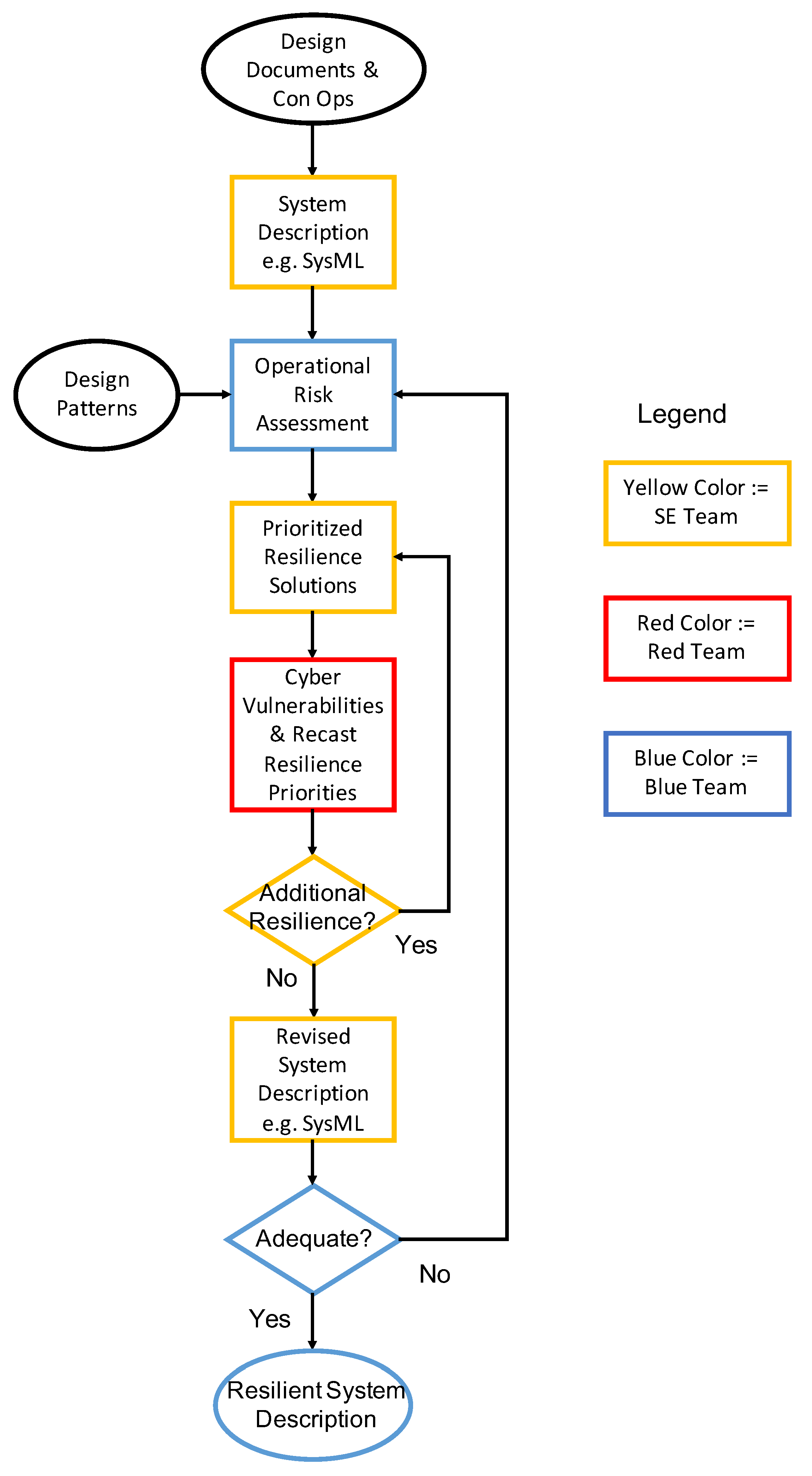
CSRM begins with a high level system description produced by the SE team and then proceeds in an iterative fashion making use of the various teams and their expertise. The steps of CSRM and the teams involved at each step are described as follows, also shown in
Figure 2:
High level, tool-based, system description produced by the SE team, including the basic system architecture and functional description in a medium such as the systems modeling language (SysML) via requirement diagrams, activity diagrams, block definition diagrams, and internal block diagrams.
Blue team—operational risk assessment, whose deliverable is a prioritized list of undesirable functional outcomes, and consequence analysis based on the system description. This is similar to, e.g., a functional hazard analysis from the aviation safety community.
SE team—derivation of prioritized potential resilience solutions based on the results of operational risk assessment.
Red team—based upon experience with cyber attack threats, COTS and GOTS cyber defense solutions and defense (and use of a analytical tools for confirmation of attack-related assumptions), prioritizes software engineering solutions, cyber defense solutions and resilience solutions.
SE team—adjusts SysML system description to account for red team recommendations and rapid prototyping/simulation results for presentation to blue team. Note that this can trigger another iteration of the process if the recast priorities require further analysis.
Blue team—responds to red team recommendations and simulation results with their revised consequence prioritization of solutions, thereby enabling SE team to provide an integrated system design discussion for requirements-related decision-makers that would include considerations of cost, as well as risk reduction. Again, this step can trigger another iteration through the process.
Generating or obtaining the system description involves a collaborative effort between the SE and Blue Teams to agree on the system’s general purpose, functionality, and mission. The use of a tool such as SysML helped communicate various intricacies in the system descriptions that may be ambiguous or difficult to convey using natural language. On the other hand, there may be issues with the relatively weak semantics of SysML that can result in inconsistencies or unrecognized gaps. This is one reason for the use of Simulink (see, e.g.,
Table 1) and will be discussed further in the conclusions. The operational risk assessment mainly involved a elicitation exercise led by the SE team but aimed at capturing the knowledge of the blue team. The consequence analysis was conducted by the SE team, allowing for the captured blue team information to be modeled in an interpretable form. The SE team accomplished this through the use of systems-theoretic tools and models such as the systems-theoretic accident model and process (STAMP) and systems-theoretic process analysis for security (STPA). The following subsection will describe these models and tools in more detail.
The remaining steps largely draw on the expertise of each of the teams to identify areas of concern within the system with respect to cybersecurity, determine the effectiveness and feasibility of possible solutions, and develop a set of cybersecurity requirements or recommendations for the final system design. The red team effort in particular allows for the use of tool-based support for providing historical evidence of cyber attacks that take advantage of similar system components or architectures. As described in [
24,
25,
26], natural language processing (NLP) techniques can be used to search attack databases and support the red team in making their judgments on the system.
Throughout CSRM, rapid prototyping and simulation can be used to demonstrate potential resilience solutions and support the expert teams [
27].
2.2. Systems-Theoretic Resiliency Assessment Tools
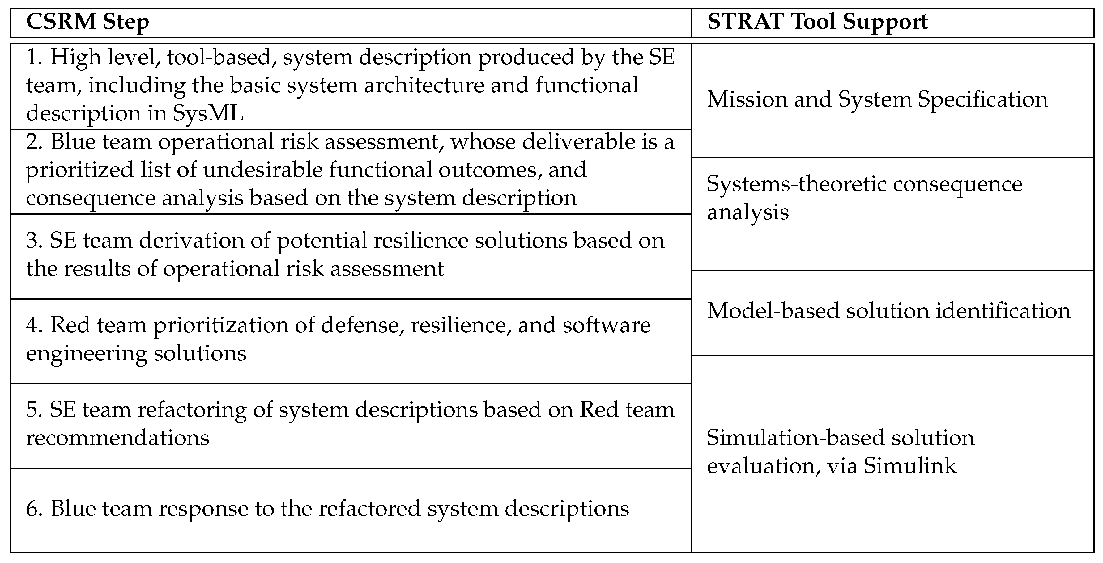
STRAT supports CSRM through the use of model-based techniques. STRAT is composed of four main components:
Mission and system specification,
Systems-theoretic consequence analysis,
Model-based solution identification,
Simulation-based solution evaluation.
The components of STRAT support several of the steps of the CSRM. This overlap is depicted in
Figure 3.
STRAT uses the initial mission and system descriptions that result directly from the first step of CSRM. Ideally, the mission and system descriptions are generated by consensus in an iterative process between the SE team and the system owners. However, if the system owners are not available for engagement or if the SE team represent the system owners, then the SE team can complete the descriptions independently. At a minimum, the initial mission description should describe in natural language:
The overall mission objective and any sub-objectives,
The greater purpose the mission supports,
Criteria for mission success and failure,
Any constraints on the environment in which the system operates to complete the mission.
Following the first step of CSRM, STRAT utilized the blue team elicitation. This meeting engaged the SE team with the system owners to elicit a prioritized set of undesirable consequences or outcomes with respect to the use of the system in the mission. Additional information, such as the components that would likely need to be attacked to produce that outcome and the potential method of attack was also collected at this stage. STRAT formalizes the relationship between these system level requirements (and undesirable outcomes) via graph theory, where requirements are connected to functional behavior, and behavior connected to the system architecture. This graph formulation will be further developed momentarily.
Following the mission and system specification, the consequence analysis identified the system’s functional control structure, behavior, and potential scenarios that might produce undesirable outcomes using the STAMP model and STPA-Sec tool. The step-by-step method for identifying this information is explained below:
Defining the purpose of the analysis is the first step with any systems engineering approach and ours is no different. From a safety perspective, some of the questions are slightly different: What kinds of losses will the analysis aim to prevent? What is the system to be analyzed and what is the system boundary?
The fundamental type of system model in STRAT is called a control structure. A control structure captures functional relationships and interactions by modeling the system as a set of feedback control loops. The control structure usually begins at an abstract level and is iteratively refined to capture more detail about the system.
To begin identifying potentially unsafe scenarios, this step analyzes control actions in the system model (control structure) to identify how they could lead to the losses defined in the mission specification. These unsafe control actions can then be used to refine the requirements and constraints in the mission specification. There are four basic types of unsafe control actions:
- (a)
Providing a control action causes a hazard
- (b)
Not providing a control action causes a hazard
- (c)
Incorrect timing or improper order of control actions causes a hazard
- (d)
A control action is applied too long or stopped too soon.
The next step is to reason about why unsafe control might occur in the system. Scenarios are created to explain:
- (a)
How incorrect feedback, design errors, failures, and other factors could cause unsafe control actions.
- (b)
How safe control actions are provided but then not followed or executed properly.
The third component of STRAT involves the creation of the system model based on the consequence analysis. By using a graphical model, STRAT allows for the visualization of the control actions available to the system, the resultant changes to the system, and the emergence of mission-level consequences from those actions. This graphical representation, known as the specification graph—or S-graph [
28]—necessitated a special definition of its graphical objects due to the complex nature of the different types of information it represents.
The S-graph encoded the relationship between three different aspects of the system: (1) the system’s mission or functional requirements; (2) the system’s functional behavior; and (3) the system structure, or architecture. The mission specification of a cyber–physical system is a graph that includes all the information presented in the mission requirements, how those relate to the system function, and how these functions are realized through the system structure, or architecture. The edges of the graph define associativity between any of the elements presented in the vertices that represent the three aspects described above, including directionality of the relationships.
Once all artifacts (requirements, functions, architectural elements) are identified, the S-graph traced mission requirements to their respective behavioral and architectural elements. This constructed a fully traceable model, potentially reducing the number of architectural components that are assessed for their security posture. For example, an in-flight entertainment system of an aircraft may be vulnerable to an attack, but (assuming the system is physically disconnected from unsecured networks) the S-graph will not include the entertainment system because there is no traceability from the architectural elements, to mission-critical function, to mission-critical requirements.
In terms of the systems- and control theory that underlies STAMP and STPA [
10], the three aspects of the S-graph are mapped to six “types” of vertices that represent physical states in the system, the controllers, actuators, sensors, and consequences. The S-graph used three types of edges that represent the flow of information between vertices, feedback from sensors, or conditions that define a consequence. Further details of the S-graph can be found in [
28].
From the S-graph, a system simulation model is built in Simulink. The simulation was designed such that the different vertices and edges in the S-graph related to particular model-building elements available in Simulink. The mapping of S-graph elements to Simulink model elements is presented in
Table 1.
Constructing the Simulink model as described in [
29] allows the simulation model to test the effect of model inputs, parameter changes, additional noise, and other model changes on the presence or absence of hazardous consequences arising from system operation. The testing of changes to the Simulink model motivates the choice and placement of resilience strategies intended to address cyber attacks designed to produce the outcomes acheived in the simulation. For example, if a parameter change in the Simulink model results in the occurrence of a hazardous outcome, then an appropriate resilience strategy involves implementing a monitor that checks for changes to that parameter in the system.
Finally, CSRM (suppported by STRAT tools) evaluates the identified potential resilience strategies in a risk-based format. The choice of which resilience strategies to implement is a multi-criteria decision problem primarily involving the cost of the solution, the impact of the solution on the adverse outcome(s) to be mitigated, and the likelihood of the adverse outcome(s) occurring. Ignoring the cost dimension, this problem formulation resembles the traditional definition of risk—the product of likelihood and consequence. From the Simulink model, the likelihood dimension is a qualitative measure of the ease in which adverse outcomes are created by changes to the simulation. Following the above example, if a simple parameter change results in an adverse outcome, it may be deemed a high-likelihood target for attack. Accordingly, the definition of consequence came from the blue team consequence elicitation and a judgment of the impact of a particular solution. For example, if the parameter change attack mentioned previously leads to a high priority consequence, then the parameter monitor solution is a high-consequence solution.
Evaluating each potential solution in terms of these two dimensions allows recommendations to be formed based on the placement of solutions within a traditional risk-matrix, or “stop light chart”. Validation of the methods involved two external, independent evaluators. One evaluator focused mostly on steps 3–6 of CSRM, and the group included several cyber security experts that composed an independent red team. In addition, a group of system operators closely associated with the case study system helped validate the models and risk assessments produced in steps 1 and 2.
3. The Silverfish Case Study
CSRM, along with the STRAT tools, is applied to a case study to test for efficacy on a hypothetical new system. This system, known as Silverfish, is a hypothetical weapon system deemed to be sufficient in terms of realistically representing a weapon system that could be used by the Army to perform a particular mission.
The system is defined as follows. The Silverfish system performs an area denial mission to aid the protection of a strategically sensitive location. More specifically, Silverfish deploys a set of 50 ground-based weapon systems, known as obstacles, that can engage unauthorized persons or ground vehicles within the denied area. The denied area measures up to approximately 0.16 square miles in size, with each obstacle being capable of protecting a 300 foot by 300 foot area. A set of surveillance sensors including static infrared and video cameras and target characterization sensors, such as acoustic and seismic sensors, provided situational awareness by monitoring the area for persons and vehicles. An unmanned aerial vehicle also provided surveillance and early warning information by monitoring the periphery of the denied area. The Silverfish operator controlled the obstacles and situational awareness sensors remotely from a nearby vehicle that can be maneuvered to give the operator “eyes-on” monitoring over portions of the denied area. The operator has control over the obstacles’ armed or disarmed states and fire capabilities. He or she uses the situational awareness information available to determine target identity and the appropriate obstacle with which to engage the target. A wireless network relayed the operator’s commands from the control station to the obstacles. Furthermore, the operator had the ability to communicate with a command and control center to receive orders and additional situational awareness information. The system operated according to the following assumptions:
Purpose: deter and prevent, when and where necessary, via the use of rapidly deployable obstacles, adversarial tracked vehicles or individuals from trespassing into geographic areas that are close to strategically sensitive locations.
Prohibited area: 100 acres of open field space. At maximum speed a vehicle would take about three minutes to cross the prohibited area.
Obstacle deployment: about 50 obstacles were available to be distributed over the 100 acre protected area (each obstacle is designed to protect a foot area). Each contained six short-range sub-obstacles, each covering a 60-degree portion of a circular area to be protected.
Operation: the operator, located in a vehicle that was operated close to the prohibited area (150 m away), remotely controlled individual obstacles and their sub-munitions, based upon sensor-based and operator visual surveillance of the prohibited area.
Prohibited area surveillance: the operator was supported by obstacle-based acoustic and seismic sensors that can detect and distinguish between vehicles and people, redundant infrared sensors that can detect and track the movement of people and vehicles, and real-time video/IR derived early warning information regarding people and vehicles approaching the prohibited area provided by a unmanned aerial vehicle (UAV) managed by the operator. The UAV was used to provide warning information.
Obstacle design features: the obstacle-based sensors provided regular operator situation awareness reports when they detected a trespasser, reports on their location, their on-off status, and their remaining battery life. The obstacle confirmed the acceptance of commands and the actual firing events.
Infrared sensor configuration: a single pole-mounted IR sensor was assumed to be capable of providing surveillance of the entire protected area. A second sensor was provided for redundancy, and could be used to provide surveillance of areas that the single sensor was not able to observe.
Requirements for avoiding errors: concerns existed regarding activating sub-obstacles in cases where non-adversarial vehicles or people, by chance, entered the prohibited area. Concerns also existed about failing to fire munitions when an adversary was approaching a strategically sensitive location via the prohibited area. The operator, when possible, could use visual observations to increase confidence regarding fire control.
Operator functions: the operator could set the obstacles into either on or off modes and can cause individual or designated groups of obstacles/sub-munitions to detonate when in “on” mode. Obstacles can be commanded to self-destroy designated critical information in order to prevent adversaries from collecting such information for their own purposes. The operator can also launch a quad-copter drone (UAV) to provide video/IR based early warning information regarding potential trespassers of the protected area.
Communications systems: the communication system includes digital interfaces that supported formatted data transfers between the operator’s system, the UAV subsystem, the individual obstacles, the IR subsystem, and the C2 Center.
Operator control station: The operator was provided with a vehicle-mounted computer(s) subsystem that provided situation awareness information including individual obstacle status and sensor-based situation awareness information. The subsystem also provided computer-based entry and corresponding system feedback for control inputs from the operator.
Command center controls: the C2 center digitally provided system control information for the operator (determines obstacle system on/off periods, provided warning of periods of higher likelihood of attack, provides forecasts of possible approach direction to the prohibited area, enables operation with/without UAV support, etc.).
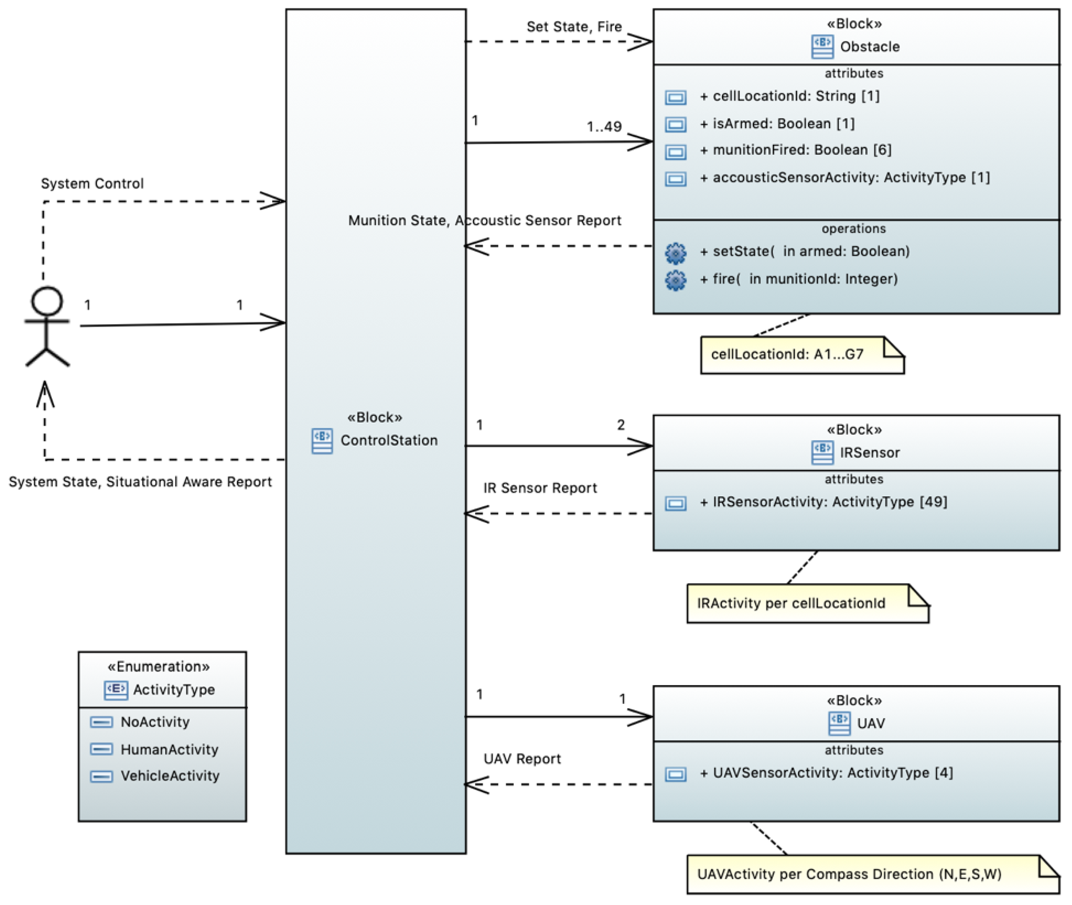
A high-level, architectural representation of Silverfish is presented in
Figure 4, using SysML. More details about the hardware and software design can be found in [
27]. The rationale for modeling the architecture in this way was based on Leveson’s STAMP accident model [
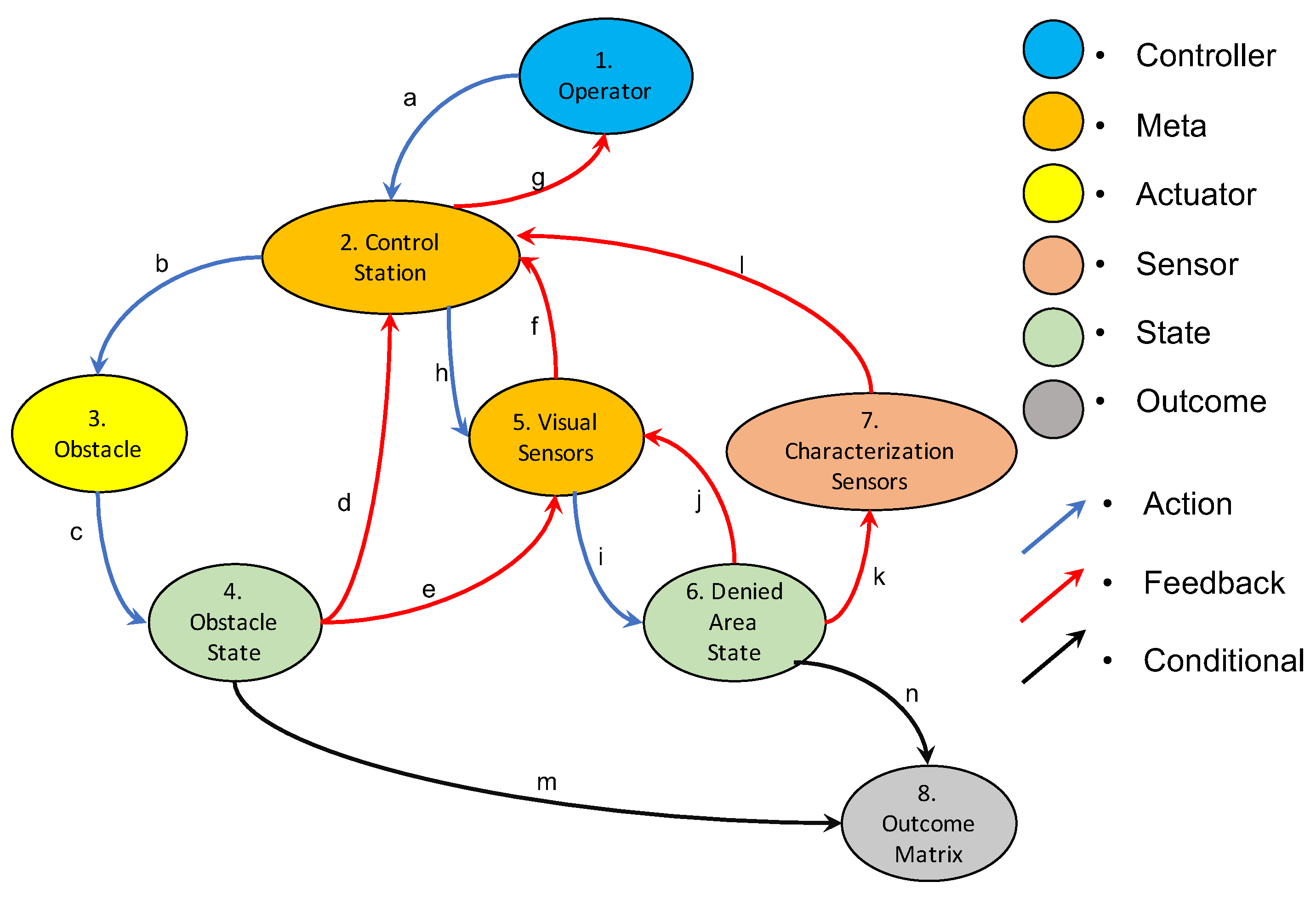
10], and the basic control structure of the Silverfish system was defined using the control theoretic notions from STAMP. Note that STAMP typically depicts the control structure vertically, while the block definition diagram depicts the control structure horizontally. Silverfish is decomposed into its main controllers, sensors, actuators, and controlled processes. Based on the system description, Silverfish consisted of an operator who controlled the obstacles and visual sensors through a control station over a wireless network. This involved the operator overseeing three controlled processes: fire control, surveillance, and target characterization. The operator managed all three processes through the control station. The obstacles actuated fire control commands, the visual sensors actuated surveillance and target characterization, and the characterization sensors (acoustic and seismic) also enabled target characterization. The sensors provided feedback to the operator on the three controlled processes via the control station.
4. Results
This section summarizes the results of the methodology and tools on the Silverfish case study. A discussion of the results follows.
4.1. CSRM Results
CSRM relies on a system description, which was generated for this case study using SysML, and an example description and corresponding SysML representation are presented in
Figure 4 and
Figure 5.
Based on only the system description from above and the operators’ experience, the first step of CSRM produced the list of undesirable consequences—as well as their relative importance—as defined by the blue team. Note that these undesirable consequences are agnostic to being caused by cyber attacks or any other particular type of causal factor. This list is presented in
Table 2.
Based on these consequences, the SE team identified three areas for resilience solutions in the Silverfish system. The SE team started with the system description in step one and proceeded with an experience-based design process. The identified areas for design improvement are as follows:
Resilient weapon control capabilities (including data consistency checking design pattern, and diverse redundant HW/SW) implementation for the operator’s vehicle-mounted computer);
Diverse redundant communications sub-systems,
Resilient situation awareness capabilities (including diverse redundant sensor voting and situation awareness introspection design patterns).
There are valid counter-arguments to diverse redundancy in software, as well as challenges in voting across truly diverse, or disparate, signals. In terms of diverse redundancy, these notions of resilience are focused on, for example, sensing modalities. In particular, diversity can be achieved through the sourcing of the hardware; in this case the sensors or communication devices are “diverse” because they come from different vendors, rely on different hardware, and may even be sensing different parts of the system.
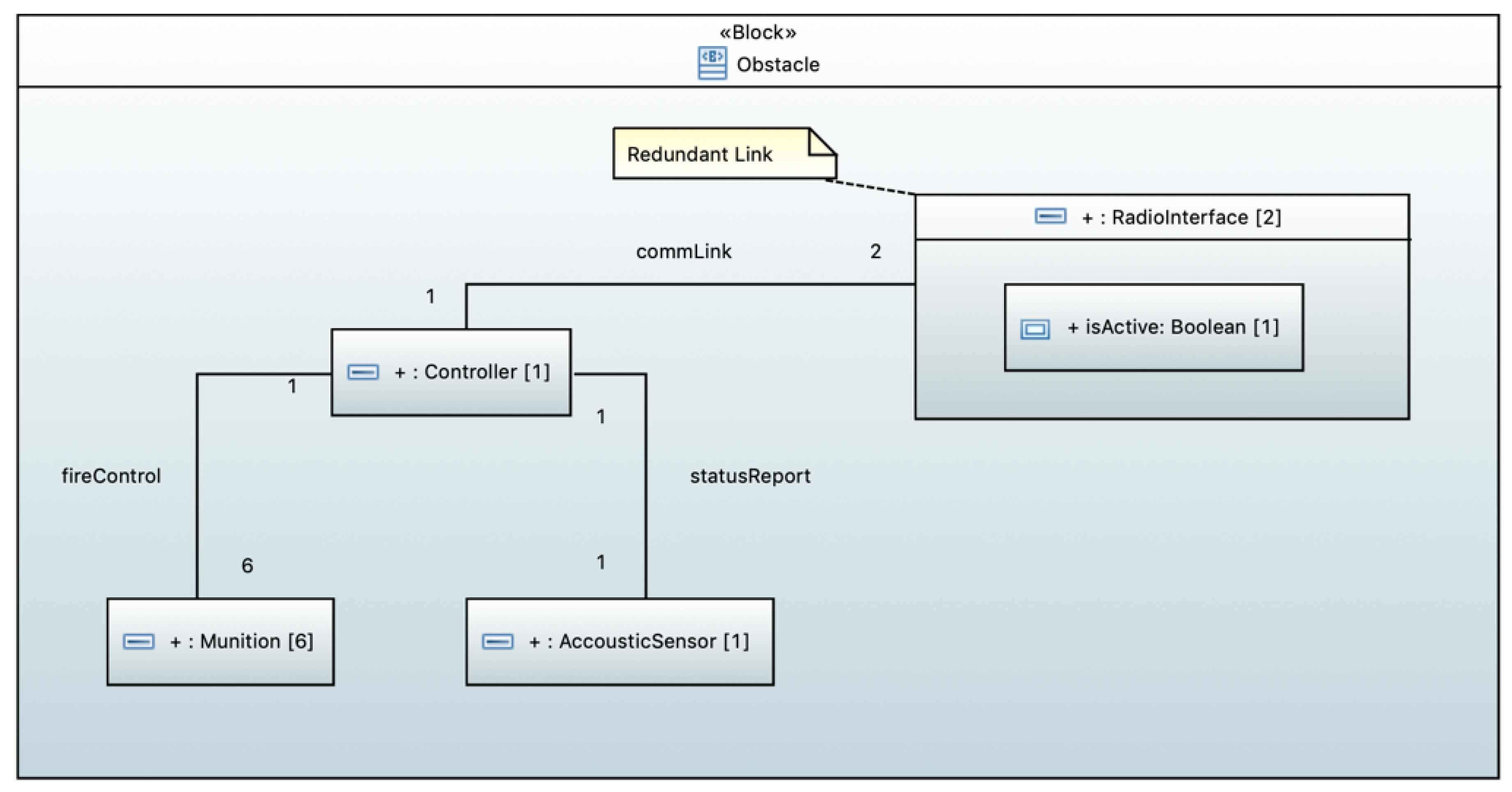
The Silverfish SysML descriptions were augmented with the various resilience solutions prior to the red team meeting in step 4. A sample of the resilience solution is presented in
Figure 5. The obstacle included six munitions, which can be independently fired, and a single acoustic sensor. The sensor was capable of distinguishing between human and vehicle activity and fed into the overall situational report provided to the system operator. As part of the resilient system design, the obstacle supported diverse redundant wireless radio interfaces. Seamless network switching is supported if triggered in response to a cyber-attack.
The next step involved a review of the various Silverfish architectures by the red team based on their expertise and tool-generated evidential support from historical attack databases. The red team meeting generated a set of eight conclusions:
Based upon the weapon control integrity requirements as provided in the Silverfish functional description, and assumed by the SE team in their SysML descriptions, encryption was a desirable security requirement.
From a software engineering perspective, separation of the weapon control system HW/SW from the situation awareness related HW/SW, including separate operator displays, should be a design requirement. This was strongly influenced by the projected relative complexity of the situation awareness related software when compared to the control software required for weapon control.
Based on the highly focused weapon control sub-system functionality, use of the following SW development practices for the weapon control functions should be required: utilization of a rich suite of software quality tools (including static and dynamic test tools), extensive use of end to end testing, and an assembly of a high-end team of SW designers/developers focused on weapon control software development.
Assuming adoption of the isolation and proposed development practices for weapon control software, it was suggested that the lowest priority be assigned to a diverse redundancy resilience requirement for weapon control (i.e., resilience was less critical if the hardware/software implementation made attacks addressed to the weapon control function sufficiently difficult).
Suggested adoption of voice-only military communications system to higher levels of command in order to avoid potential attacks through the C2 system.
Considered the communication sub-system as highest priority for resilience, using diverse redundancy to address attacks resulting in denial of service and message delays.
Suggested that the resilience design for situation awareness be the second highest priority for resilience, including diverse redundant IR sensors as a basis for addressing both reliability and cyber attack resilience requirements.
Suggested considering adding an operator authentication design requirement should the possibility exist for potential scenarios that require interactions across separately protected, closely located protected areas.
Next, CSRM simply integrated the red team suggestions into the Silverfish descriptions before the final meeting with the blue team in step 6. In this particular implementation of the CSRM, the blue team concurred with the red team’s assessment of the Silverfish system. Based on the inputs of the three teams, the final recommendations of the CSRM with respect to the Silverfish system can be summarized as pursuing resilient design patterns for weapon control capabilities, diverse communication subsystems, and situational awareness capabilities.
4.2. Results from Using the STRAT Tools
The results of the STRAT are based on the same system description as that of the CSRM. The consequence analysis, while very similar, generates a different system model.
Following the guidelines for the STAMP-based consequence analysis, as described in [
29], the main unacceptable losses to the system were as follows:
Enemy forces or other unauthorized persons/vehicles traverse the denied area without the operator’s knowledge or intent,
Friendly forces, civilians, or other non-combatants are killed or harmed by Silverfish,
Silverfish obstacles are fired without a valid target.
Additional hazards were defined based on the methods described above in
Section 2.2, and more detailed results can be found in [
29].
Table 3 includes the high level hazards.
The above unacceptable losses and additional hazards form a subset of the potential outcomes described in the S-graph of the Silverfish. The rest of the S-graph is largely based on Silverfish’s control functional structure. The block diagram of this structure is presented in
Figure 4.
Combining the results of the STAMP-based consequence analysis with the control structure defined above directly forms the S-graph. The S-graph for the Silverfish system is presented in
Figure 6. Currently, the S-graph is not a “model” in the sense of MBSE in that it does not (yet) have formal semantics, executability, or tool support. At this point, it conceptually demonstrates the linkage between the notions of control- and systems-theoretic models of STAMP, the architecture and requirements from SysML, and hazard analysis, and how these are ultimately combined and translated into Simulink.
We should note that SysML and its many vendors have simulation capabilities, and there also exist third-party parametric solvers for SysML within Simulink. These are interesting research directions and potential extensions of our work, and this will be discussed further in the conclusions. However, our justification for translating between SysML to Simulink via a guided, yet manual, step using the S-Graph is as follows. First, in general the simulation capabilities of Mathworks exceed those of most SysML toolsets. Second, we wanted to simulate the trajectory of a potential target (i.e., a human walking through an area) and then observe the various transitions and decisions in the Silverfish system. These kinds of dynamics lend themselves naturally to Simulink. Ultimately, the combination of the architectural view (among other things) of SysML and the dynamics that were easily modeled in Simulink lend to potential synergy, as has been explored elsewhere [
30,
31].
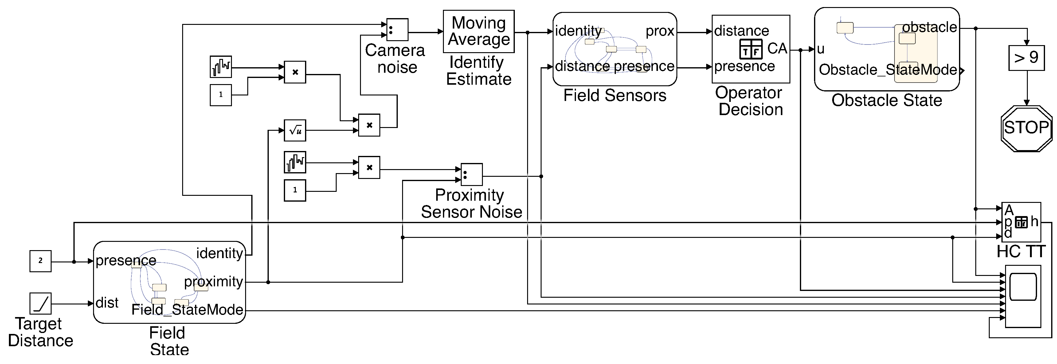
This S-graph structure is transformed into a Simulink model using the mapping described in
Table 1. The overall Simulink model is shown in
Figure 7 and an example sub-block of that model is shown in
Figure 8.
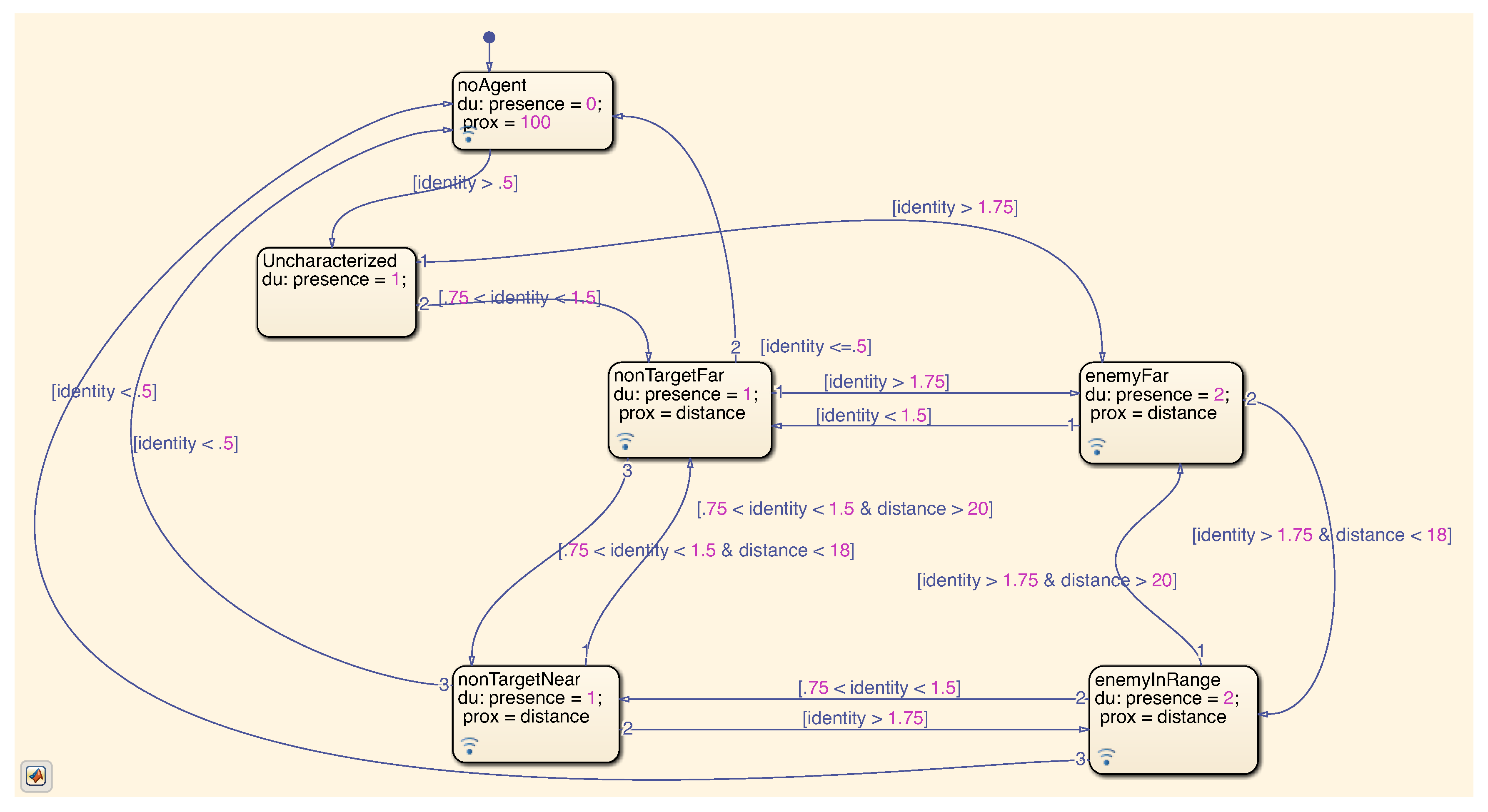
Figure 8 represents the state machine that takes an intruder’s identity and distance estimate as input, and then returns states “proximity” and “presence” to indicate to the operator whether there is a threat. There are several other examples of state machines and truth tables in the overall Simulink model.
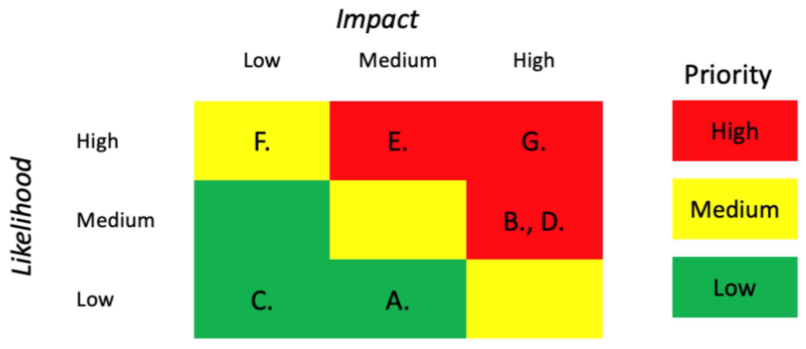
Analysis of the Simulink model based on the blue team-derived consequences led to the identification of seven potential resilience solutions. These solutions, their location in the Silverfish system, and the consequences or hazards they address are presented in
Table 4.
These solutions were then evaluated based on performance with respect to the likelihood and consequence metrics described in
Section 2. This paper focuses on model-based approaches to evaluating vulnerabilities and how those map to (potentially undesirable) outcomes, as well as the evaluation of resilience alternatives. Although not the focus of this paper, this section briefly describes the prioritization of alternatives. Each resilience solution can be evaluated in terms of (a) the number of outcomes—Blue team results in
Table 2—addressed and (b) the priority of outcomes. Solutions that address a large number of high priority outcomes will have a higher impact rating. Similarly, likelihood is a qualitative measure of a combination of (a) the number of changes needed to achieve an undesired outcome and (b) the severity of those changes. If an attacker must make a large number of changes to the system, and each change is drastic or challenging, this results in a low likelihood rating. A summary of the evaluation results is presented in
Table 5 and
Figure 9.
In summary, STRAT identified four resilience solutions as having high-priority for implementation in the final system design: system parameter assurance, diversely redundant hopping command sending capability, two-factor command authorization, and backup communication abilities. These solutions address the most simple means of producing undesirable consequences based on Silverfish’s system description. As one would expect, confusing the commands sent from the operator to the obstacles or shutting down the communication network render the system unable to accomplish its mission. As such, the solutions that address those concerns receive the highest priority for implementation. Although the risk matrix is currently populated in a qualitative fashion, it is an open problem to develop, implement, and validate more quantitative metrics. Reasoning about impact is relatively more straightforward, assuming one has properly elicited priorities from the appropriate stakeholders. However, quantifying what is naturally a qualitative decision is fraught with difficulty and is the subject of much ongoing work in decision-theory. Reasoning about likelihood is even more difficult, especially given that (a) the detrimental results could be due to an unknown adversary with unknown resources and (b) this assessment occurs during early design phases. It is for these reasons that perhaps a qualitative risk assessment is not only adequate but also appropriate and honest.
4.3. Discussion of CSRM and STRAT
Discussing the results of CSRM to STRAT must first be qualified by the slight difference in goals between using CSRM alone or using the tool-based support from STRAT. First and foremost, the CSRM intends to develop cyber security requirements for a developing system. Such requirements include the incorporation of both resilience and traditional security solutions into the system design along with recommendations about software engineering practices. Using STRAT, as with any tool, has the potential to limit flexibility relative to a purely human-driven, creative process. In addition, by its nature, STRAT focuses more on the identification and evaluation of resiliency strategies. Keeping this difference in mind, the results of both CSRM with and without STRAT are in agreement with each other.
In general, CSRM identified a broader selection of resilience strategies than STRAT. This could be a result of the abstraction of system hardware components in STRAT’s definition of the control structure and system model. CSRM defined the existence of certain hardware components explicitly in SysML representations, which likely aided the experts with the identification of resilience strategies such as separating situational awareness information from weapon control functions.
5. Discussion and Conclusions
While both CSRM and STRAT have slightly different purposes, the similar results from CSRM with and without STRAT suggest that the use of tool support is both possible and of value. CSRM is inherently heavily based on the use of experts and their experience. Such reliance leads to generally well-received recommendations, but strains budgets in terms of time and manpower. STRAT utilizes significantly less manpower and produces similar results in a shorter period of time when compared to the CSRM alone. Consequently, this opens up the opportunity for increased scalability and more efficient distribution of workloads.
By using STRAT to identify resilience solutions instead of a meeting of experts, which is both costly and difficult to arrange, the team of experts can be used as a confirmation method for the results produced by STRAT. This allows the experts to move from producing the set of solutions to checking and potentially trimming or augmenting the solution set. This change in responsibility offers the potential for reduced time requirements for subject matter experts, allowing them to allocate time to more projects and more effectively utilize their experience.
Furthermore, the benefits of integrating STRAT and CSRM into a holistic cybersecurity requirements procedure extend to the creation of a common framework to be applied to new systems. Such a framework would allow designers, system owners, and auditors to better understand the rationale behind particular design choices and their impact on the cyber-risks to the system. The advantage of this is obvious.
Achieving this holistic approach, however, requires future work both in terms of the capabilities of STRAT and CSRM. CSRM currently has limitations in generating a perspective on the costs associated with the cybersecurity requirements it produces. The integration of cost into the recommendation process would add both an extra dimension to the multi-criteria decision problem inherent in system design, as well as offering additional means for rationalizing design choices. STRAT shares this same limitation with respect to cost analysis and would similarly benefit from future research in that area. Furthermore, STRAT would benefit from an expansion of scope to include cyber-defense solutions as well as software engineering best-practice recommendations to align with the stated goals and scope of CSRM.
Additional future work lies in the creation of automated analysis for the models generated by STRAT. Opportunities for automation exist in the search for potential solutions based on the model as well as solution performance. For example, to assist automating the analysis or assuring consistency in the results, the methodology can leverage a more formal, concise language for attacks on CPS [
1,
2]. In addition, although the S-graph captures a notion of propagation of an attack on a CPS to catastrophic (physical) effects, these works are more explicit about the relationship between classes of attacks and classes of physical system responses. As discussed in the previous section, additional work should focus on the automatic translation from SysML to Simulink, or using solvers in Simulink that can easily ingest the many types of diagrams that can come from SysML. In addition, native SysML does not have the semantics for many of the timing and synchronization techniques used in CPS. This is an important topic for the broader research community and general research directions for systems engineering. For example, architecture analysis and design language (AADL) [
32] would better address these particular challenges, as well as other tools from formal methods, e.g., UPPAAL [
33]. Finally, further research into performance metrics would allow for more granular descriptions of solution performance and better inform the choice of particular design patterns over others.
In summary, this paper presented two related methodologies for addressing cybersecurity at the earliest stages of a new system’s life cycle. The integration of both methodologies presents an opportunity for the creation of a holistic approach to designing and developing more secure cyber–physical systems. The melding of subject-matter experts with model-based techniques offers the potential of automation, increased scalability, and greater efficiency. While both methodologies provide added benefit if applied separately, a joint application and integration would greatly increase confidence and assurance in new systems.

 ,
, 


