
Nonsingular Terminal Sliding Mode Control of PMSM Based on Improved Exponential Reaching Law

1
School of Electrical and Electronic Engineering, Changchun University of Technology, Changchun 130000, China
2
State Key Laboratory of Automobile Simulation and Control, Jilin University, Changchun 130000, China
*
Author to whom correspondence should be addressed.
Electronics 2021, 10(15), 1776; https://0-doi-org.brum.beds.ac.uk/10.3390/electronics10151776
Submission received: 12 May 2021
/
Revised: 13 July 2021
/
Accepted: 22 July 2021
/
Published: 24 July 2021
(This article belongs to the Section Systems & Control Engineering)
Abstract
:When a permanent magnet synchronous motor runs at low speed, the inverter will output discontinuous current and generate torque ripple; when the motor is runs at high speed, a large amount of stator harmonic current generates, which affects its speed following ability and torque stability. To ensure the fast and smooth switching of a permanent magnet synchronous motor in the full speed domain, this paper proposes the nonsingular terminal sliding mode control of PMSM speed control based on the improved exponential reaching law. Firstly, the improved exponential reaching law is composed of the state variables and power terms of the sliding mode surface functions. The reaching law function is designed in sections to balance the fast dynamic response of the system and chattering control. Secondly, an improved exponential reaching law based on the sliding mode control strategy of the PMSM speed loop is proposed. By designing the initial value of the integral term in the nonsingular terminal sliding mode surface function, the initial state of the system is located on the sliding mode surface. The integral sliding mode surface is used to reduce the system steady-state error, while the proposed sliding mode reaching law is used to increase the arrival speed and suppress system chattering, ultimately affecting modeling error problems, complex working conditions, and uncertainty factors. This paper proposes a sliding mode observer based on an improved exponential reaching law to compensate for the disturbances. Lyapunov stability theory can prove that this system can make the speed tracking error converge to zero in finite time. Hardware-in-the-loop experiments were used to validate the effectiveness of the proposed method.
1. Introduction
The traditional motor drive mode is that of a motor plus a reducer. The existence of the reducer not only increases the overall energy consumption of the transmission system, but also reduces the stability and reliability of the transmission system. PMSMs have the advantages of small torque ripple, high efficiency, simple structure, small size, etc., so they are widely used in direct drive systems [1,2,3,4]. A direct drive system can reduce the intermediate links of the transmission system (such as reducers, coupling, etc.), and “near zero transmission” can be achieved. However, because a direct drive system does not have a transmission mechanism, disturbance on the load side will affect the stability of the PMSM speed control system. In addition, because the PMSM is a complex system of nonlinear, strong coupling, and multivariable systems, it also has problems such as modeling errors, complex operating conditions, and uncertain factors. The control performance and reliability of the PMSM will directly affect the stable operation of the entire system. Therefore, a PMSM need a robust control strategy to improve the anti-disturbance ability of the motor.
At present, to make PMSM suitable for various and complicated applications, higher requirements have bene put forward for its speed regulation system. The common control algorithms include fuzzy control [5,6], predictive control [7,8], adaptive control [9,10,11], and sliding mode control [12,13,14,15], etc. In [5], the researchers designed a fuzzy logic speed controller which not only improved the ability to suppress torque pulsation but also improved the dynamic quality of the speed control system. In [7], the researchers proposed a continuous control set sliding mode predictive control for a PMSM speed control system. In [8], the researchers proposed a model prediction method to overcome the limitations of the motion control of an unconstrained PMSM. In [10], the researchers adopted adaptive fault-tolerant control to ensure the normal operation of the actuator when it failed. In [11], the researchers proposed a combination of neural networks and adaptive control for the application of improved speed following. In [11,12,13,14,15,16], the researchers proposed that integral sliding mode control [12], fuzzy sliding mode control [13], terminal sliding mode control [14,15], and backstepping sliding mode control [16], respectively, all can be used for the speed control of a PMSM. In [12], the researchers proposed a memorial and memory-based integral sliding mode control and applied it to motor control. In [13], the researchers proposed a robust fuzzy neural network sliding mode control method for the control of permanent magnet linear motors. In [14], the researchers proposed a terminal sliding mode control that was applied to uncertain dynamic systems, but their systems suffered from singularity problems. Therefore, in [17], the researchers designed a nonsingular terminal sliding mode control to solve the singularity problems of the system, and it was analyzed, inferred, and proven in detail. In [18], the researchers proposed an adaptive second-order nonsingular terminal sliding mode method which was applied to the trajectory tracking of autonomous underwater vehicles. Compared to other control methods, the sliding mode of the system was designed independently, so it is not affected by parameter disturbances or external disturbances. The NTSM has the advantages of fast dynamic response, finite time convergence, and high steady-state accuracy, so it is widely used in the field of high precision control.
However, the superior performance of sliding mode control is traded for high-frequency chattering, which is directly associated with the switching function contained in the reaching law. Different approaches had been developed to suppress chattering, such as the higher-order sliding mode [19,20], adaptive algorithms [21,22], the researchers prposed disturbance observers [23,24,25] and reaching law methods [26,27,28,29]. In [19,20], the researchers proposed a high-order sliding mode control strategy and gave a detailed overview. The discontinuous control in the higher-order sliding mode control is hidden in its higher-order derivatives, which effectively suppress chattering. But this control structure is complicated. In [22], the researchers proposed an adaptive algorithm acting on the parameter estimation of the sliding mode and provided a parametric fitting mechanism to learn the dynamic properties of the system, which made the system reach speed. In [23], the researchers proposed a control method that not only effectively improved the incompatibility between rapidity and stability, but also solved the problem that the constant rate reaching law cannot satisfy both rapidity and low chattering in the sliding mode observer. In [24,25], the researchers proposed an extended state observer to observe lumped disturbances, and the estimated disturbances were introduced into feedforward compensation technology to improve the robustness of the system. Uncertainty disturbances are the main source of chattering in sliding mode control, which can be solved by using an observer. The reaching law method is simple to design, easy to implement, and widely used. In [26], Weibing Gao proposed the reaching law and analyzed it in the three modes of sliding, arriving, and steady-state. The most applied is the exponential reaching law. This reaching law not only shortens the arrival time but also reduces the speed of the moving point when it reaches the switching surface. In [27,28], the researchers proposed a new reaching law takes the sliding mode surface as the research mechanism and designed different functions to make the exponential function adapt to changes to the sliding mode surface and state. In [29], the researchers proposed a power reaching law for electronic throttle control in automobiles. The power reaching law uses the property of exponential functions to accelerate the speed of the approach in different stages. In addition, there are other methods to suppress system chattering, such as the neural networks were used for the online approximation of interference to reduce the gain of switching items [30], multi-objective optimization of sliding modes [31], etc.
Aiming at PMSM starting speed overshoot, sudden speed changes are caused by the slow dynamic response and other problems. In this paper, an improved exponential reaching law was proposed based on [27], which is used to improve the transient response time and anti-disturbance performance of a PMSM speed regulation system. A speed controller was designed using an improved exponential reaching law. When the uncertainties in the system could not be measured, a sliding mode observer was proposed to achieve the estimation of disturbances. The other parts of this paper are organized as follows: in Section 2, an improved exponential reaching law is designed. Section 3 presents the mathematical model of the PMSM with uncertainty disturbance and designs the speed controller using an improved exponential reaching law. In Section 4, the SMO is designed using the improved exponential reaching law. Section 5 compares the proposed method with simulations. Section 6 concludes with a summary.
2. Improved Exponential Reaching Law Design
2.1. Commonly Used Sliding Mode Reaching Law
The sliding mode structure means that the system is forced to follow a certain trajectory of modal motion by purposeful and constant changes according to the current state of the system. The advantages of sliding mode control include insignificant parameter changes, external disturbance changes, fast response of the system, and simple implementation. However, the disadvantage is that the state variable cannot always move along the prescribed track. The chattering phenomenon is caused by repeated traversal on the sliding mode surface. Therefore, the reaching law method is proposed to suppress chattering, and the exponential reaching law is as follow [26]:
where is the sliding mode surface, is the signum function, and are the system parameters.
In (1), when , it can be obtained that
and the reaching time can be calculated by integrating (1) from 0 to , with
The exponential approach rate method is widely used. However, although the accessibility problem can be solved by adding the constant velocity term , the exponential arrival law of the velocity to the sliding mode surface is determined by the value of the design parameter . Therefore, it is important to balance arrival speed and suppress chattering. The chattering phenomenon and slow reaching speed in the traditional sliding mode approach law are discussed. At present, in [32], the researchers combined the exponential reaching law and single power reaching law to propose a fast power reaching law which shortens the approach time and makes the approaching process smoother, but the chattering phenomenon still exists. In [33], the researchers proposed the double-power combination function reaching law, which improved the convergence speed in the interval and avoided chattering. The reaching law of [33] is as follows:
where .
Although the function has a piecewise characteristic, the reaching law of the double-power combination function is faster than the traditional law of reaching, but the second term of the function term has a slower convergence rate than the first term. The convergence of the two terms of the function differs greatly, and the law of reaching cannot have the ability to adapt.
2.2. Proposed Improved Exponential Reaching Law
Based on the above analysis, this paper proposes a segmented rate adjustment sliding mode reaching law, which performs segmented rate adjustment to increase the rate of the system.
In this paper, a segmented rate adjustment sliding mode reaching law is designed as:
where x is the state variable of the system.
When , . Among them, is the variable speed reaching law, and is the variable index reaching law. This means that when the system approaches the sliding mode surface, the reaching law rate increases and the chattering is suppressed. When , . Among them, the variable index reaching law is . Moreover, , which increases the arrival speed. It realizes the function of adaptive adjustment according to different stages in the process of system approach, greatly improves the reaching speed of the system, and has the characteristics of global finite time convergence.
Theorem 1.
For the sliding mode reaching law (5), the system stateconverges to the equilibrium zero under its action.
Proof.
According to Equation (5), we can get:
if , there is .
According to the existence and reachability conditions of the continuous system sliding mode, if is satisfied, the reaching law exists, and the equilibrium point can be reached. □
Theorem 2.
For Equation (5), suppose the initial state ofis, then the stateconverges to 0 within the finite time, and the upper limit ofis.
Where,.
Proof.
When , Equation (5) can be expressed as:
When , it can be seen that the system will reach the sliding mode surface in finite time by integrating Equation (7) from to :
Because , in Equation (8), it can be rewritten as:
When , Equation (5) can be expressed as:
When , it can be seen that the system will reach the sliding mode surface in finite time by integrating (10) from to :
Because in Equation (11), it can be rewritten as:
Therefore, when the initial state is not in the sliding mode surface, i.e., , the time taken for the initial state to reach the sliding mode surface is:
In summary, the convergence time of the reaching law (5) is less than . □
2.3. Discrete Form of NSMRL
In engineering applications, real-time computer control is a discrete control system. From the perspective of discrete analysis, when is close to 0, the discrete form of NSMRL is given, and the performance of the exponential reaching law in the discrete state is compared. In a discrete system, the sliding mode surface function is designed as follows:
where .
Next, the switching band surrounding the switching surface is represented as follows:
If is close to 0, the improved exponential reaching law proposed by Equation (5) can be simplified to , and the discrete expression is as follows:
where represents the sampling period.
Assuming that the system gradually reaches the sliding surface in a finite time, this indicates that the system will reach the sliding surface in two situations or , then the equation of the next period can be obtained with
Similarly, when , Equation (16) can be expressed as:
Through Equations (17) and (18), the thickness of the discrete improved exponential reaching law for (16) is:
Then, the switch thickness of the traditional sliding mode reaching law is expressed as:
Combining Figure 1, it can be seen that the improved exponential sliding mode reaching law, due to the introduction of the power of the state variable, enables the system to stably reach the origin and cause smaller chattering.
On the other hand, for the PMSM speed regulation system, the speed of the motor follows its ideal value rapidly and stably, which is an important performance index of the control system. In this paper, the speed error is directly used in the design of the reaching speed of the sliding mode, and it can accelerate the rate of the system state variable reaching the sliding mode surface and reduce chattering.
2.4. Simulation Analysis
To verify the dynamic properties of the proposed sliding mode reaching law (5), the second-order nonlinear system is established as follows:
The sliding mode surface function is described as follows:
where satisfies system stability.
The derivative of the sliding mode surface is obtained as follows:
Using the reaching law in (5) and substituting it into (23), the control input of (21) can be obtained as follows:
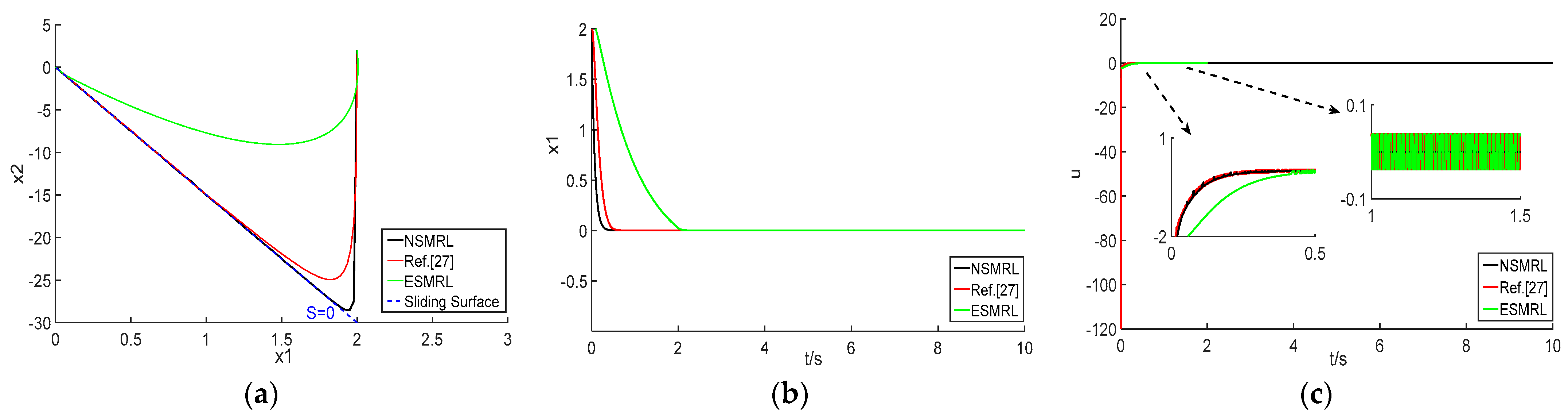
To verify the dynamic performance of the NSMRL, the ESMRL and the reaching law in [27] were selected for comparison experiments, where and , and the controller parameters were , , and . The initial state of the system .
3. NSMRL Design for PMSM Speed Controller
3.1. PMSM Mathematical Model
In a rotor synchronous coordinate system, time-varying parameters such as voltage and permanent magnet chain are transformed into nontime-varying parameters, and the following equations can be established according to the basic characteristics of the motor [34]:
where , are the voltages of the -axes, , are the stator current, , are the inductance of the stator, is the number of poles pairs, and the flux linkage.
The torque equation of PMSM is:
The motion equation of PMSM is:
where is the torque, is the load torque of the motor, is the moment of inertia, and is the viscous damping coefficient.
And (25) can be rewritten as:
Combining (25) and (26) can be written as:
For surface-mounted motors , and considering parameters and external disturbances, (29) can be rewritten as:
where are external disturbances.
Selecting the parameter , the expression is as follows:
Because the motor variables are bounded, the total system disturbance satisfies the following equation:
where is the limit value of the total system disturbance.
Therefore, (30) can be rewritten as:
Taking the system state variable:
where is the reference speed, and is the actual speed.
Substituting (33) into (34), the expression of the equation of the PMSM is obtained when the effect of parameter uncertainty is considered:
3.2. NSMRL for PMSM Speed Controller
To avoid the singularity problems of TSM, a nonsingular integral type terminal sliding mode surface was selected in this paper [35]:
where .
Then, the derivative of (36) is:
Substituting the NSMRL (5) into (37), we obtain
Obtain the control amount :
Because of the unmeasurable speed and disturbances, (38) can be rewritten as:
4. The Sliding Mode Observer Based on NSMRL
4.1. Design of the SMO
Because of the uncertainty of parameters, external disturbances, and other factors, the SMO is designed. In the PMSM vector control, the load torque variation can be regarded as constant during the control cycle because the control cycle is short, and the load disturbance changes slowly compared with the current and speed, i.e., .
Choosing the speed and the system disturbance as the state variables, torque as the system input, and as the system output, the SMO equations can be described as:
The speed and system disturbances are the observation objects, so (40) can be written as:
where and are estimated values, z1 and z2 are the observer gain, and are the sliding mode rate of the SMO.
Define the observation error of the observer:
The integral sliding mode surface is selected for the SMO:
The sliding mode rate of the SMO is designed:
4.2. Stability Analysis
To verify that the sliding mode observer (41) and sliding mode control strategy (5) can effectively estimate the system error and achieve fast tracking of the ideal speed, the Lyapunov stability function can be described as:
where .
Then, the derivative of is:
Substituting (39) into (46):
Then, the derivative of is:
Assuming that g is a slow-varying signal (), (41) can be rewritten as:
Substituting (49) into (48):
Substituting (33) and (26) into (49):
Combining (44), (46), and (50), we can obtain that .
From Lyapunov’s stability theorem, ensures the stability of the designed SMO in terms of tracking error and achieves reaching in finite time to achieve the ideal speed.
5. Experimental Validation
To verify the effectiveness of the method proposed in this paper, an xPC-Target-based hardware-in-the-loop testbed was built as shown in Figure 3. The testbed includes two industrial control machines, motors, and controllers. One of the IPCs was used as the host PC and equipped with the PMSM control algorithm. The Simulink model was compiled into real-time operational C code and downloaded to the target PC. Another IPC was used as the xPC target PC, running DOS-dependent xPC real-time cores to execute RTW-compiled real-time C code. The two PCs connected and communicated through TCP/IP, and the developer downloaded the Simulink model to the target PC through the host PC. The two PCs could monitor/debug the operation of the target P in real time. The important parameters of the PMSM are given in Table 1, and the controller section parameter selection was , , , and .
The block diagram of the PMSM speed regulation system is shown in Figure 4a. The working principle of block diagram Figure 4a is as follows: Firstly, through Clarke and Park transformation of the PMSM stator, the three-phase AC ia, ib, ic, the id excitation current and the iq torque current were obtained.
Secondly, the double closed-loop system structure was used to control the speed of PMSM. The inner loop is a current loop, and PI control can eliminate the current error of the d–q axis and improve current tracking performance. By adjusting the PI controller parameters, the motor can meet the demand of rapid current response under different working conditions. The outer loop is a speed loop, and it is easily affected by load and parameter perturbation in the actual operation of the motor.
Therefore, this paper proposes an improved exponential reaching law based on the sliding mode control strategy of the PMSM speed loop to achieve speed following at start-up, given speed, and load changes.
Finally, after the current loop was adjusted, the voltage command in the d–q axis was obtained. The SVPWM space voltage vector synthesis method was used to control the motor.
The block diagram of the speed control structure is shown in Figure 4b. The state variable of the speed control system is the speed error, i.e., . The first half is the calculation of the sliding mode surface function s, and the second half is the improved exponential reaching law. This part constitutes the speed control.
5.1. Start Process
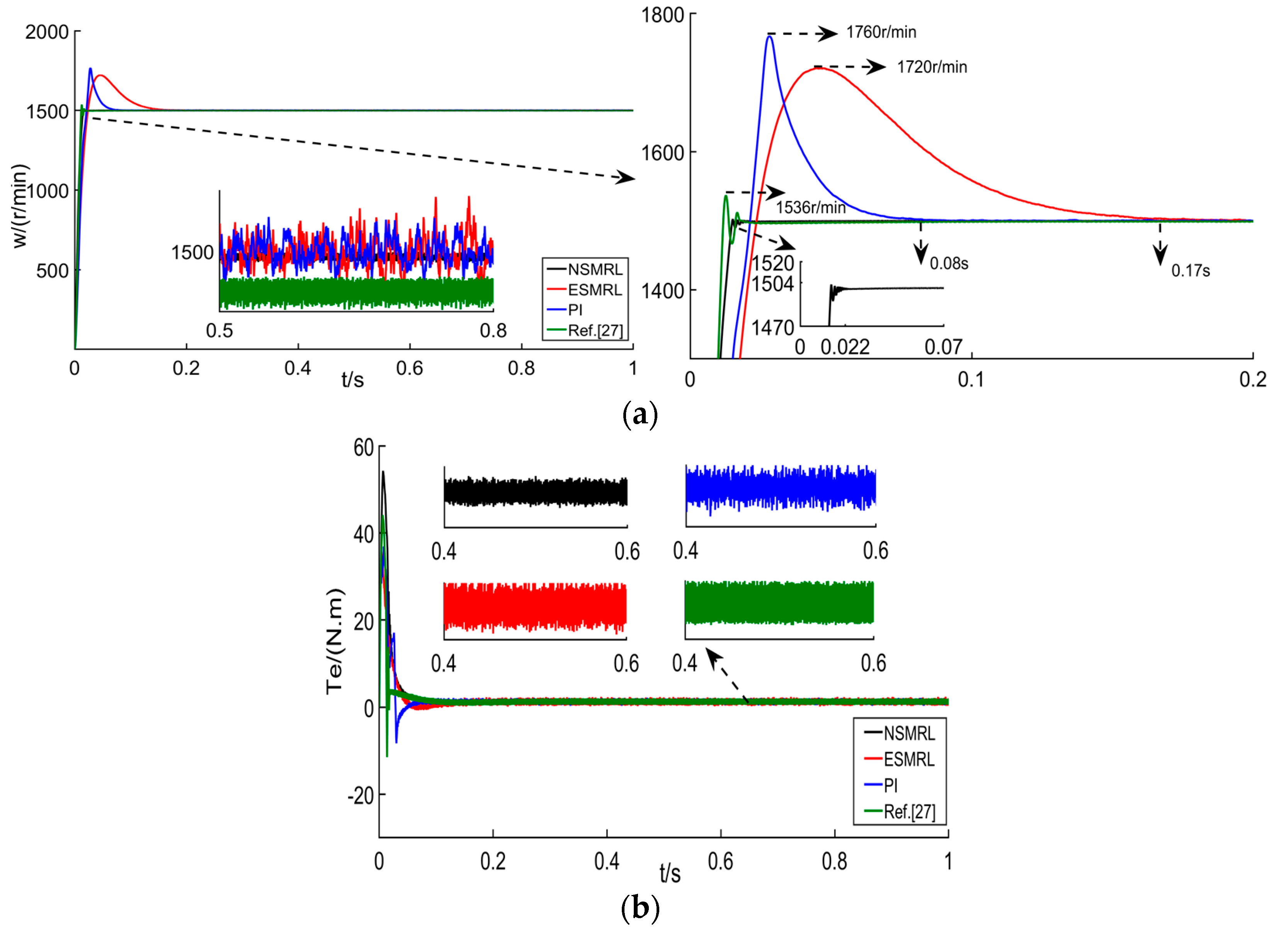
The start speed performance of the PMSM under different reaching laws was compared in detail. The reference speed was 2500 r/min, and the torque responses under PI, NSMRL, ESMRL, and [27] during the start transient process are shown in Figure 4a,b.
It can be concluded from Figure 5a,b that the start-up transient process NSMRL [27], and PI had 0.2%, 0.4%, and 2% overshoot, respectively. Moreover, the settling process of the speed response under NSMRL, ESMRL, PI, and [27] was 0.025 s, 0.06 s, 0.15 s, and 0.055 s, respectively. The speed response under Method 1 was 58.3%, 83.3%, and 54.5% faster than those of the ESMRL, PI, and [27]. Figure 4b shows that the torque chattering phenomenon under NSMRL was smaller than those of ESMRL, PI, and [27].
Furthermore, Figure 6a,b show the reference speed of 1500 r/min and torque responses, respectively.
It can be concluded from Figure 6a,b that the start-up transient process of PI, NSMRL, ESMRL, and [27] had 17.3%, 0.16%, 14.7%, and 2.4% overshoot, respectively. NSMRL had a small fluctuation but still reached the reference speed without overshoot. The speed chattering phenomenon under NSMRL+SMO was smaller than that of ESMRL, PI, or [27]. Furthermore, Figure 6b shows that the torque chattering phenomenon under NSMRL was smaller than that of ESMRL, PI, and [27]. The comparison data are listed in Table 2.
5.2. Loading Process
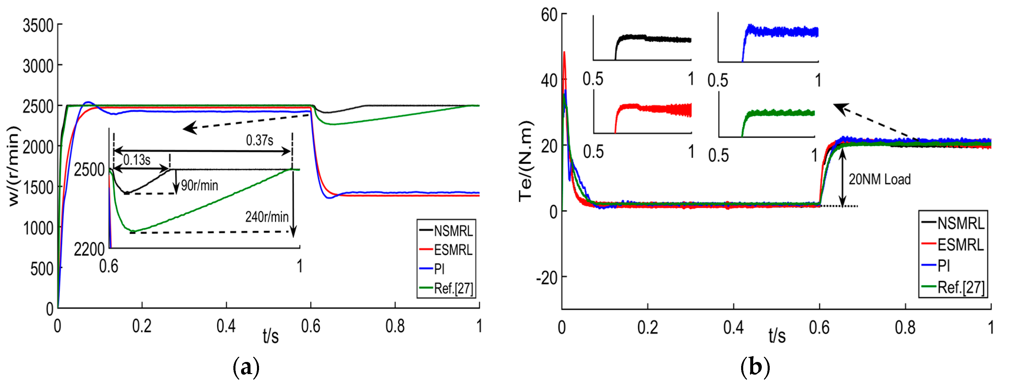
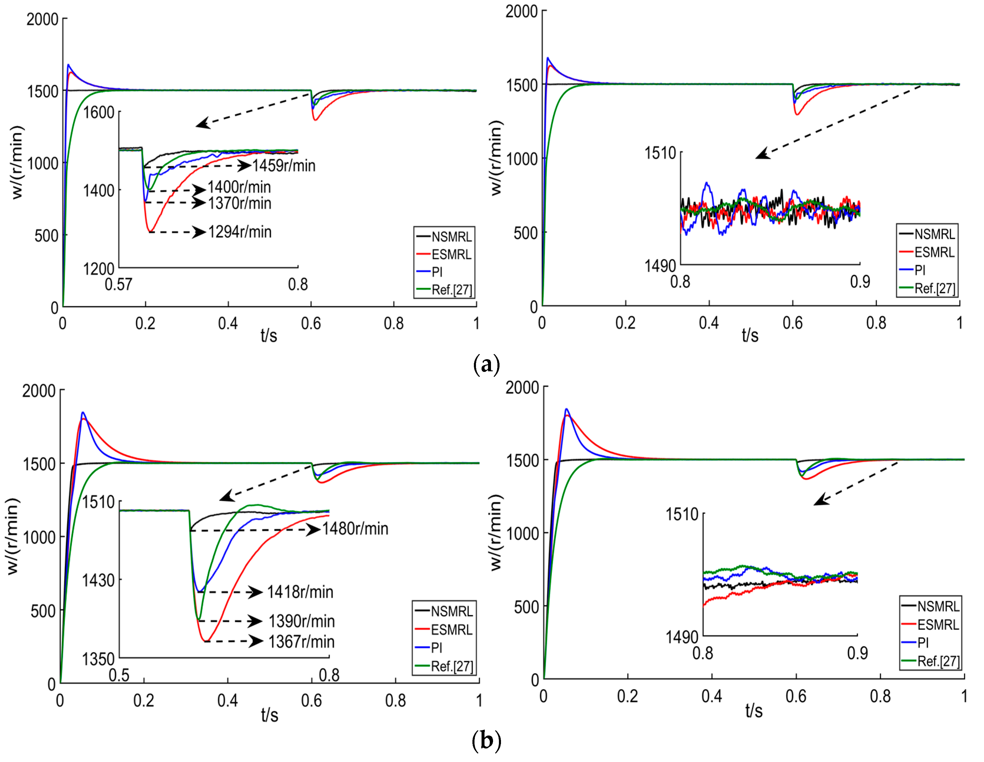
The speed performance of the PMSM under PI, NSMRL, ESMRL, and [27] were compared under loading conditions. The speed and torque responses were taken with a load of 20 Nm at a reference speed of 2500 r/min, as shown in Figure 7a,b.
It can be concluded from Figure 7a that because of the selection of the high speed of 2500 r/min and the large load of 20 Nm, both PI and ESMRL were unable to recover the reference speed after loading. In addition, as seen in Figure 7a, the speed dropped under NSMRL and [27] to 90 r/min and 240 r/min, respectively. Furthermore, the settling transient process of the speed responses at the loading point under NSMRL and [27] were 0.13 s and 0.37 s, respectively.
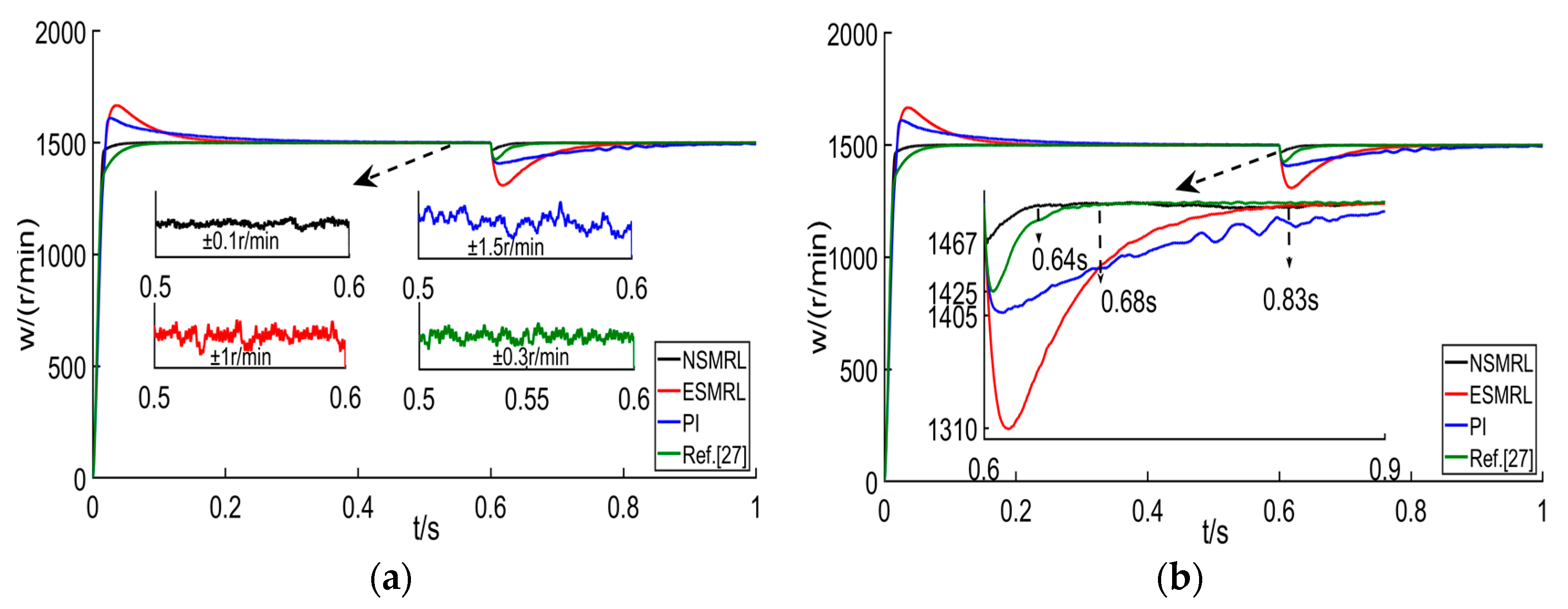
Moreover, Figure 8a,b show the load of 10 Nm at the speed of 1500 r/min responses.
It can be concluded from Figure 8a that the speed fluctuation range under PI, NSMRL, ESMRL, and [27] was ±0.1 r/min, ±1 r/min, ±1.5 r/min, and ±0.3 r/min, respectively. Figure 8b shows that the speed drops under NSMRL, EMERL, PI, and [27] were 33 r/min, 190 r/min, 95 r/min, and 75 r/min, respectively. Therefore, the NSMRL had a small steady-state error range and low torque chattering. For more visual analysis, the comparison data are listed in Table 3.
5.3. Variable Acceleration or Loading Process
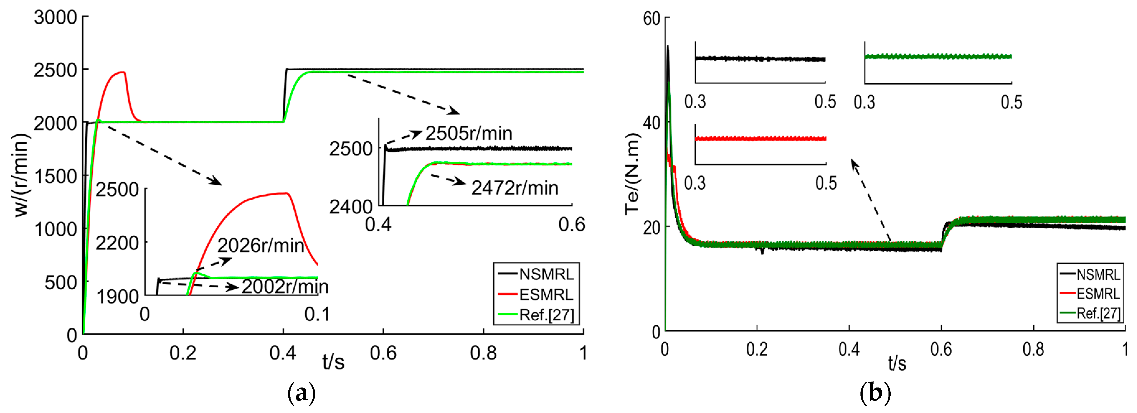
The speed performances of the PMSM under PI, NSMRL, ESMRL, and [27] were compared under variable acceleration and loading responses. The speed was from 2000 r/min to 2500 r/min, and the torque was from 15 Nm to 20 Nm, as shown in Figure 9a,b.
It can be concluded from Figure 9a that the start-up transient process of NSMRL and [27] had 0.1% and 1.3% overshoot, respectively. In addition, when accelerating from 0.4 s to 2500 r/min, although there was a slight fluctuation in the speed of the NSMRL, the system could ensure that the motor reached the reference speed quickly, while the ESMRL and [27] could not reach the reference speed.
5.4. Speed Process under Parameter Change
The speed performance of the PMSM under four control methods with 0.5 J and 2 J parameter changes under a load of 10 Nm are shown in Figure 10a,b.
It can be concluded from Figure 10a that the speed drop under NSMRL, EMERL, PI, and [27] was 41 r/min, 206 r/min, 130 r/min, and 100 r/min, respectively. Although the speed fluctuation based on NSMRL was not the smallest at a steady-state, this method has a small speed drop and rapid recovery at a 0.5 J inertia mismatch. Furthermore, Figure 10b show that the speed drop under NSMRL, EMERL, PI, and [27] was 20 r/min, 133 r/min, 82 r/min, and 110 r/min, respectively. The comparison data are listed in Table 4.
6. Conclusions
In this paper, nonsingular terminal sliding mode control of a PMSM based on an improved exponential reaching law was proposed to solve the problems of large overshooting speed, large torque pulsation at low speed, and slow dynamic response caused by sudden change of speed and load. Firstly, the improved exponential reaching law was applied to a nonlinear system, and the validity of the reaching law was verified by quantitative analysis from three aspects, trajectory motion of the sliding mode phase, the convergence process of the state variables, and the output curve. Secondly, an improved exponential reaching law-based PMSM speed loop sliding mode control strategy was proposed to realize speed following when upstart and speed load changed. Finally, considering the effects of uncertainty factors such as speed and disturbances under different working conditions, a SMO was designed using an improved exponential reaching law. The hardwire-in-loop experiment verifies that, compared with other methods, the SMO can realize no overshoot start, small torque pulsation at low speed, improved dynamic response when the speed changed, small load speed drop when the motor operated, and small torque pulsation when the torque changed. Therefore, this control strategy helps to improve the speed control quality and suppress torque pulsation.
Author Contributions
Conceptualization, C.J. and N.Z.; methodology, Q.W.; software, Q.W.; validation, Q.W., Z.L. and N.Z.; formal analysis, N.Z.; investigation, H.D.; resources, C.J.; data curation, N.Z.; writing—original draft preparation, Q.W.; writing—review and editing, N.Z. and C.J.; funding acquisition, C.J., H.D. and N.Z. All authors have read and agreed to the published version of the manuscript.
Funding
This research was funded by Haitao Ding of the National Natural Science Foundation of China, grant number U1864206, Niaona Zhang of the National Natural Science Foundation of China, grant number 2017YFB0103600 and 2017YFB0103700, Changhong Jiang of the Science and Technology Development Plan of Jilin Province, grant number 20200403037SF.
Institutional Review Board Statement
The study was conducted according to the guidelines of the Declaration of Helsinki, and approved by the Institutional Review Board (or Ethics Committee) of Changchun University of Technology.
Informed Consent Statement
Informed consent was obtained from all subjects involved in the study. Written informed consent has been obtained from the patient(s) to publish this paper.
Conflicts of Interest
The authors declare no conflict of interest.
References
- Feng, G.; Lai, C.; Li, W.; Li, Z.; Kar, N.C. Efficient Permanent Magnet Temperature Modeling and Estimation for Dual Three-Phase PMSM Considering Inverter Nonlinearity. IEEE Trans. Power Electron. 2020, 35, 7328–7340. [Google Scholar] [CrossRef]
- Li, X.; Zhang, L.; Ying, H.; Huang, S.; Zhang, Q. Study of suppression of vibration and noise of PMSM for electric vehicles. IET Electr. Power Appl. 2020, 14, 1274–1282. [Google Scholar] [CrossRef]
- da Cunha, G.; Rossa, A.J.; Alves, J.A.; Cardoso, E. Control of Permanent Magnet Synchronous Machines for Subsea Applications. IEEE Trans. Ind. Appl. 2018, 54, 1899–1905. [Google Scholar] [CrossRef]
- Liu, X.; Chen, H.; Zhao, J.; Belahcen, A. Research on the Performances and Parameters of Interior PMSM Used for Electric Vehicles. IEEE Trans. Ind. Electron. 2016, 63, 3533–3545. [Google Scholar] [CrossRef]
- Wang, C.; Zhu, Z.Q. Fuzzy Logic Speed Control of Permanent Magnet Synchronous Machine and Feedback Voltage Ripple Reduction in Flux-Weakening Operation Region. IEEE Trans. Ind. Appl. 2020, 56, 1505–1517. [Google Scholar] [CrossRef]
- Mani, P.; Rajan, R.; Shanmugam, L.; Joo, Y.H. Adaptive Fractional Fuzzy Integral Sliding Mode Control for PMSM Model. IEEE Trans. Fuzzy Syst. 2019, 27, 1674–1686. [Google Scholar] [CrossRef]
- He, L.; Wang, F.; Ke, D. FPGA-Based Sliding-Mode Predictive Control for PMSM Speed Regulation System Using an Adaptive Ultralocal Model. IEEE Trans. Power Electron. 2021, 36, 5784–5793. [Google Scholar] [CrossRef]
- Tarczewski, T.; Grzesiak, L.M. Constrained State Feedback Speed Control of PMSM Based on Model Predictive Approach. IEEE Trans. Ind. Electron. 2016, 63, 3867–3875. [Google Scholar] [CrossRef]
- Nguyen, A.T.; Rafaq, M.S.; Choi, H.H.; Jung, J. A Model Reference Adaptive Control Based Speed Controller for a Surface-Mounted Permanent Magnet Synchronous Motor Drive. IEEE Trans. Ind. Electron. 2018, 65, 9399–9409. [Google Scholar] [CrossRef]
- Li, D.; Li, P.; Cai, W.; Song, Y.; Chen, H. Adaptive Fault-Tolerant Control of Wind Turbines with Guaranteed Transient Performance Considering Active Power Control of Wind Farms. IEEE Trans. Ind. Electron. 2018, 65, 3275–3285. [Google Scholar] [CrossRef]
- Chaoui, H.; Khayamy, M.; Okoye, O. Adaptive RBF Network Based Direct Voltage Control for Interior PMSM Based Vehicles. IEEE Trans. Veh. Technol. 2018, 67, 5740–5749. [Google Scholar] [CrossRef]
- Zhang, J.; Liu, X.; Xia, Y.; Zuo, Z.; Wang, Y. Disturbance Observer-Based Integral Sliding-Mode Control for Systems With Mismatched Disturbances. IEEE Trans. Ind. Electron. 2016, 63, 7040–7048. [Google Scholar] [CrossRef]
- Lin, F.; Shen, P. Robust Fuzzy Neural Network Sliding-Mode Control for Two-Axis Motion Control System. IEEE Trans. Ind. Electron. 2006, 53, 1209–1225. [Google Scholar] [CrossRef]
- Wu, Y.; Yu, X.; Man, Z. Terminal sliding mode control design for uncertain dynamic systems. Syst. Control. Lett. 1998, 34, 281–287. [Google Scholar] [CrossRef]
- Mu, C.; He, H. Dynamic Behavior of Terminal Sliding Mode Control. IEEE Trans. Ind. Electron. 2018, 65, 3480–3490. [Google Scholar] [CrossRef]
- Shieh, H.-J.; Shyu, K.-K. Nonlinear sliding-mode torque control with adaptive backstepping approach for induction motor drive. IEEE Trans. Ind. Electron. 1999, 46, 380–389. [Google Scholar] [CrossRef]
- Feng, Y.; Yu, X.; Man, Z. Non-singular terminal sliding mode control of rigid manipulators. Automatica 2002, 38, 2159–2167. [Google Scholar] [CrossRef]
- Qiao, L.; Zhang, W. Adaptive Second-Order Fast Nonsingular Terminal Sliding Mode Tracking Control for Fully Actuated Autonomous Underwater Vehicles. IEEE J. Ocean. Eng. 2019, 44, 363–385. [Google Scholar] [CrossRef]
- Li, P.; Yu, X.; Zhang, Y. The Design of Quasi-Optimal Higher Order Sliding Mode Control via Disturbance Observer and Switching-Gain Adaptation. IEEE Trans. Syst. Man Cybern. Syst. 2020, 50, 4817–4827. [Google Scholar] [CrossRef]
- Yin, Y.; Liu, J.; Sánchez, J.A.; Wu, L.; Vazquez, S.; Leon, J.I.; Franquelo, L.G. Observer-Based Adaptive Sliding Mode Control of NPC Converters: An RBF Neural Network Approach. IEEE Trans. Power Electron. 2019, 34, 3831–3841. [Google Scholar] [CrossRef]
- Van, M.; Mavrovouniotis, M.; Ge, S.S. An Adaptive Backstepping Nonsingular Fast Terminal Sliding Mode Control for Robust Fault Tolerant Control of Robot Manipulators. IEEE Trans. Syst. Man Cybern. Syst. 2019, 49, 1448–1458. [Google Scholar] [CrossRef] [Green Version]
- Bartoszewicz, A.; Leśniewski, P. New Switching and Nonswitching Type Reaching Laws for SMC of Discrete Time Systems IEEE Trans. Control. Syst. Technol. 2016, 24, 670–677. [Google Scholar] [CrossRef]
- Zhang, Y.; Yin, Z.; Zhang, Y.; Liu, J.; Tong, X. A Novel Sliding Mode Observer with Optimized Constant Rate Reaching Law for Sensorless Control of Induction Motor. IEEE Trans. Ind. Electron. 2020, 67, 5867–5878. [Google Scholar] [CrossRef]
- Junejo, A.K.; Xu, W.; Mu, C.; Ismail, M.M.; Liu, Y. Adaptive Speed Control of PMSM Drive System Based a New Sliding-Mode Reaching Law. IEEE Trans. Power Electron. 2020, 35, 12110–12121. [Google Scholar] [CrossRef]
- Li, X.; Xu, W.; Ye, C.; Boldea, I. Comparative Study of Transversal-Flux Permanent-Magnetic Linear Oscillatory Machines for Compressor. IEEE Trans. Ind. Electron. 2018, 65, 7437–7446. [Google Scholar] [CrossRef]
- Gao, W.; Hung, J.C. Variable structure control of nonlinear systems: A new approach. IEEE Trans. Ind. Electron. 1993, 40, 45–55. [Google Scholar] [CrossRef]
- Wang, Y.; Feng, Y.; Zhang, X.; Liang, J. A New Reaching Law for Antidisturbance Sliding-Mode Control of PMSM Speed Regulation System. IEEE Trans. Power Electron. 2020, 35, 4117–4126. [Google Scholar] [CrossRef]
- Zhang, X.; Sun, L.; Zhao, K.; Sun, L. Nonlinear Speed Control for PMSM System Using Sliding-Mode Control and Disturbance Compensation Techniques. IEEE Trans. Power Electron. 2013, 28, 1358–1365. [Google Scholar] [CrossRef]
- Wang, H.; Shi, L.; Man, Z.; Zheng, J.; Li, S.; Yu, M.; Jiang, C.; Kong, H.; Cao, Z. Continuous Fast Nonsingular Terminal Sliding Mode Control of Automotive Electronic Throttle Systems Using Finite-Time Exact Observer. IEEE Trans. Ind. Electron. 2018, 65, 7160–7172. [Google Scholar] [CrossRef]
- Sun, T.; Cheng, L.; Wang, W.; Pan, Y. Semiglobal exponential control of Euler–Lagrange systems using a sliding-mode disturbance observer. Automatica 2020, 112, 108677. [Google Scholar] [CrossRef]
- Benamor, A.; Boukadida, W.; Messaoud, H. Genetic algorithm-based multi-objective design of optimal discrete sliding mode approach for trajectory tracking of nonlinear systems. Proc. Inst. Mech. Eng. Part C J. Mech. Eng. Sci. 2019, 233, 5237–5252. [Google Scholar] [CrossRef]
- Li, H.; Cai, Y. Sliding mode control with double power reaching law. Control. Decis. 2016, 31, 498–502. [Google Scholar]
- Liao, Y.; Yang, Y.; Wang, Y. Novel double power combination function reaching law for sliding mode control. J. Natl. Univ. Def. Technol. 2017, 39, 105–110. [Google Scholar]
- Xu, Q. Piezoelectric Nanopositioning Control Using Second-Order Discrete-Time Terminal Sliding-Mode Strategy. IEEE Trans. Ind. Electron. 2015, 62, 7738–7748. [Google Scholar] [CrossRef]
- Li, S.; Zhou, M.; Yu, X. Design and Implementation of Terminal Sliding Mode Control Method for PMSM Speed Regulation System. IEEE Trans. Ind. Inform. 2013, 9, 1879–1891. [Google Scholar] [CrossRef]
Figure 1.
Comparison of the state trajectories of the two reaching laws. (a) exponential reaching law state trajectories. (b) NSMRL state trajectories.
Figure 1.
Comparison of the state trajectories of the two reaching laws. (a) exponential reaching law state trajectories. (b) NSMRL state trajectories.
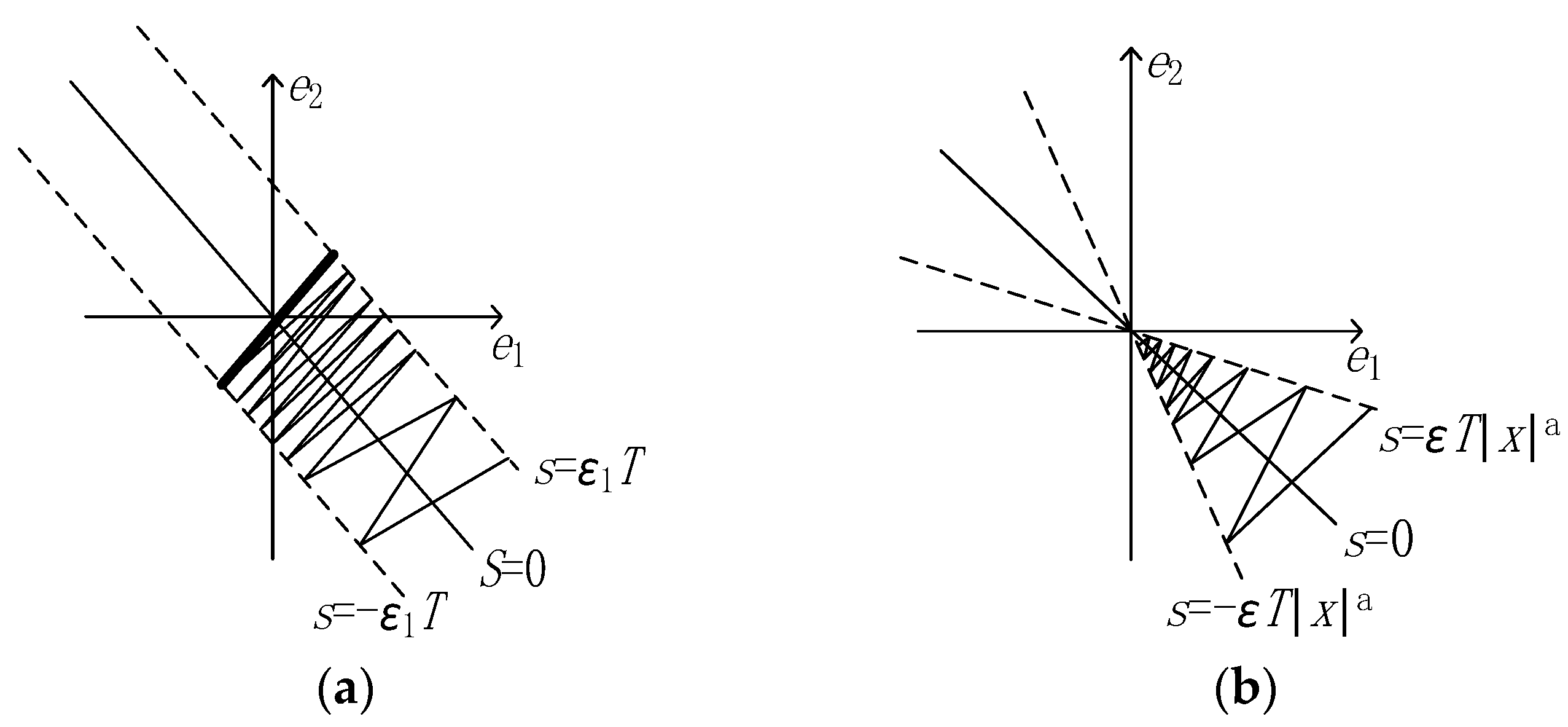
Figure 2.
Performance comparison of NSMRL, ESMRL, and [27]. (a) Phase trajectory. (b) Position error reaching rate. (c) Controller output.
Figure 2.
Performance comparison of NSMRL, ESMRL, and [27]. (a) Phase trajectory. (b) Position error reaching rate. (c) Controller output.

Figure 3.
The xPC-Target based hardware in the loop.
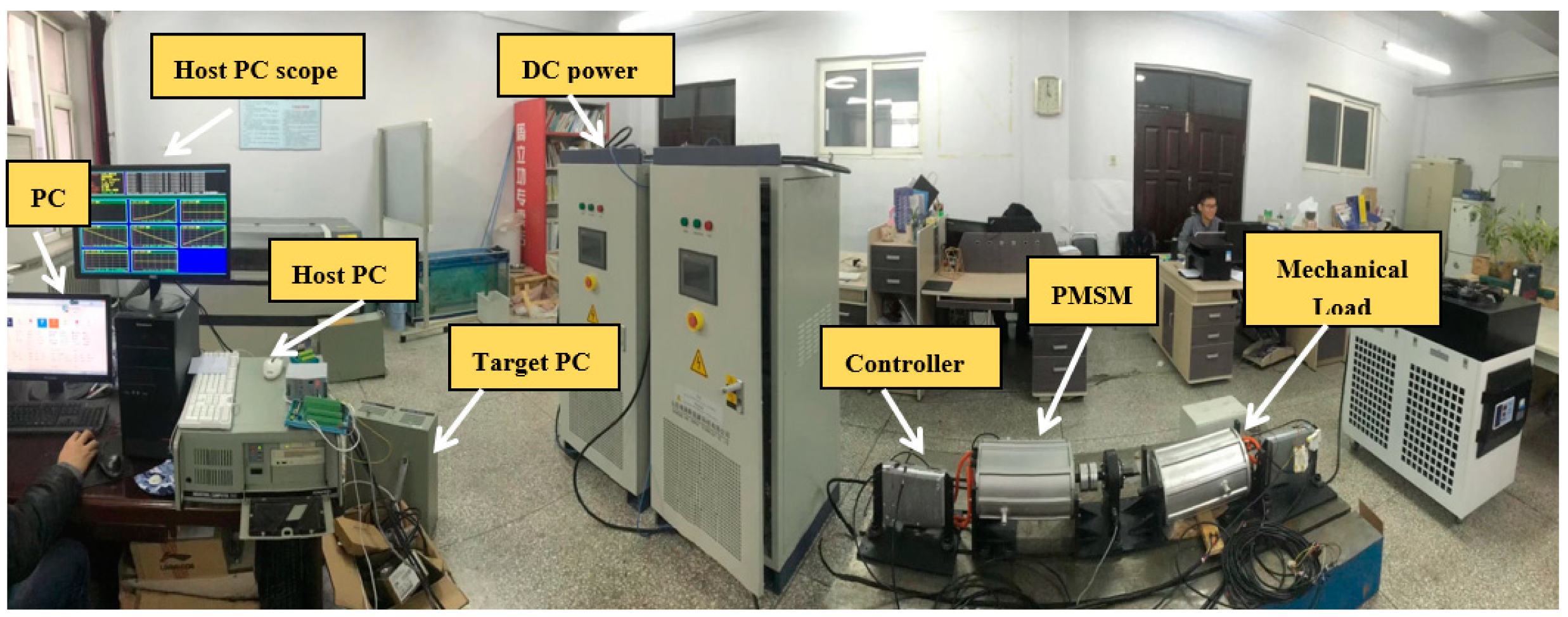
Figure 4.
(a) Block diagram of the PMSM speed regulation system. (b) Block diagram of the speed control structure.
Figure 4.
(a) Block diagram of the PMSM speed regulation system. (b) Block diagram of the speed control structure.
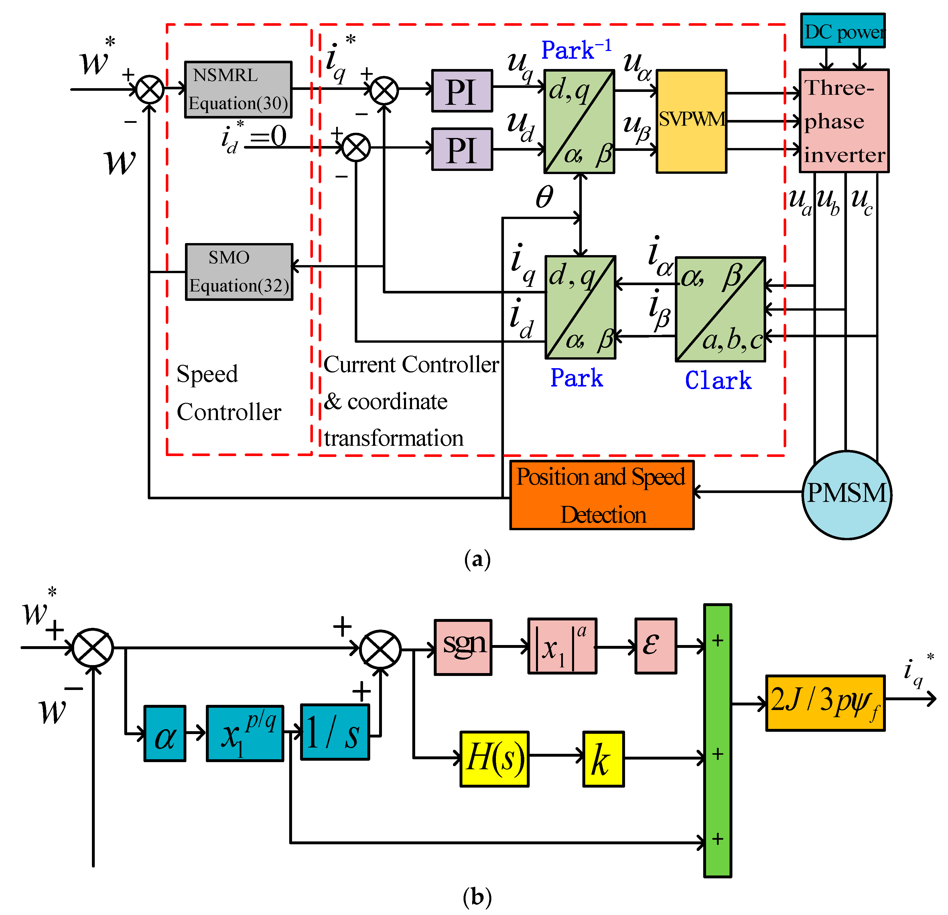
Figure 5.
The speed and torque responses under four control methods with no load in 2500 r/min. (a) Speed. (b) Torque.
Figure 5.
The speed and torque responses under four control methods with no load in 2500 r/min. (a) Speed. (b) Torque.
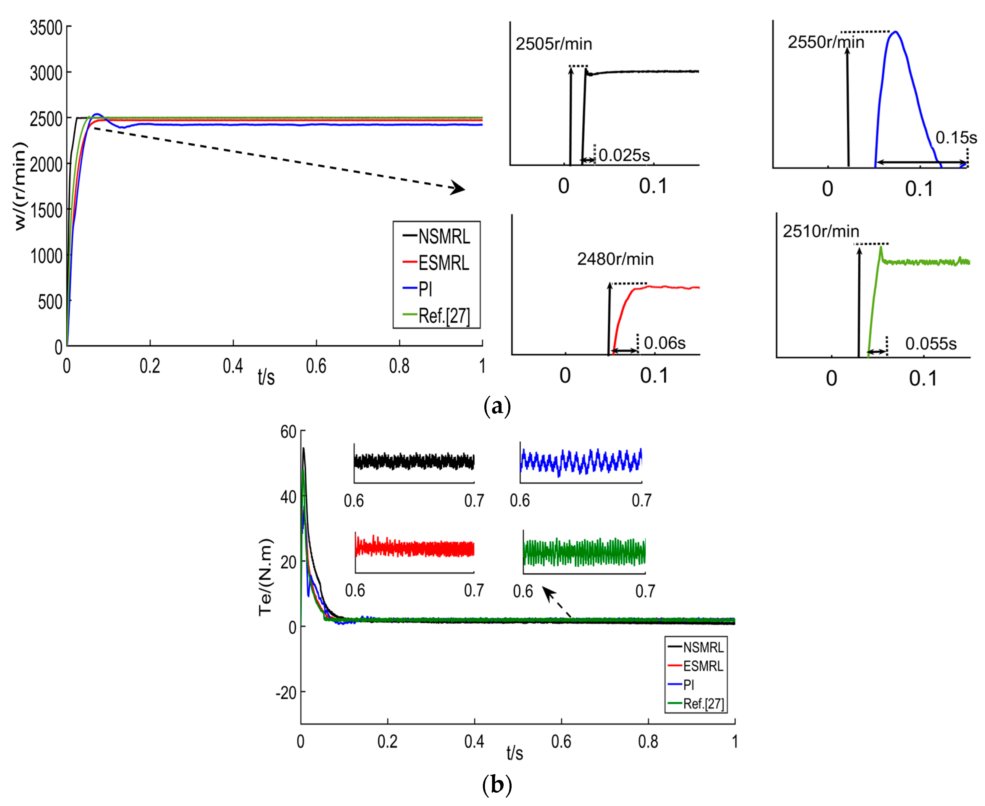
Figure 6.
The speed and torque responses under four control methods with no load in 2500 r/min. (a) Speed. (b) Torque.
Figure 6.
The speed and torque responses under four control methods with no load in 2500 r/min. (a) Speed. (b) Torque.

Figure 7.
The speed and torque responses under four control methods with the load of 20 Nm in 2500 r/min. (a) Speed. (b) Torque.
Figure 7.
The speed and torque responses under four control methods with the load of 20 Nm in 2500 r/min. (a) Speed. (b) Torque.

Figure 8.
The speed responses under four control methods with the load of 20 Nm in 1500 r/min. (a) Amplification of the overshoot. (b) Amplification of the speed drop.
Figure 8.
The speed responses under four control methods with the load of 20 Nm in 1500 r/min. (a) Amplification of the overshoot. (b) Amplification of the speed drop.

Figure 9.
The variable acceleration and loading responses under three control methods. (a) Acceleration. (b) Torque.
Figure 9.
The variable acceleration and loading responses under three control methods. (a) Acceleration. (b) Torque.

Figure 10.
The speed responses under four control methods with the load of 10 Nm. (a) 0.5 J. (b) 2 J.
Figure 10.
The speed responses under four control methods with the load of 10 Nm. (a) 0.5 J. (b) 2 J.


Table 1.
Parameters of the motor.
| Parameter and Unit | Value |
|---|---|
| DC power Vdc/V | 311 |
| Stator phase resistance R/Ω | 2.875 |
| Inductances Ld = Lq/mH | 8.5 |
| Rotational inertia J/kg·m2 | 0.001 |
| Flux linkage of permanent magnets /Wb | 0.175 |
| Viscous friction coefficient B/N·m·s | 0.008 |
Table 2.
The Speed Performance Comparison.
| Control Method | 2500 r/min | 1500 r/min | ||
|---|---|---|---|---|
| Steady Speed (r/min) | Settelling Time (s) | Overshoot | Settelling Time (s) | |
| NSMRL | 2500 | 0.025 | 0.16% | 0.02 |
| ESMRL | 2480 | 0.06 | 14.7% | 0.17 |
| PI | 2480 | 0.15 | 17.3% | 0.08 |
| Ref. [27] | 2500 | 0.055 | 2.4% | 0.022 |
Table 3.
Speed Performance Comparison.
| Control Method | NSMRL | ESMRL | PI | Ref. [27] |
|---|---|---|---|---|
| Settelling Time at Load (s) | 0.04 | 0.23 | 0.4 | 0.08 |
| Vibration error (r/min) | ±0.1 | ±1 | ±1.5 | ±0.3 |
| Speed Drop (r/min) | 33 | 190 | 95 | 75 |
Table 4.
Speed Performance Comparison.
| Control Method | 0.5 J | 2 J | ||
|---|---|---|---|---|
| Speed Drop (r/min) | Vibration Error (r/min) | Speed Drop (r/min) | Vibration Error (r/min) | |
| NSMRL | 41 | ±1.9 | 20 | ±0.4 |
| ESMRL | 206 | ±2.8 | 133 | ±2 |
| PI | 130 | ±4.3 | 82 | ±1.5 |
| Ref. [27] | 100 | ±1 | 110 | ±1 |
Publisher’s Note: MDPI stays neutral with regard to jurisdictional claims in published maps and institutional affiliations. |
© 2021 by the authors. Licensee MDPI, Basel, Switzerland. This article is an open access article distributed under the terms and conditions of the Creative Commons Attribution (CC BY) license (https://creativecommons.org/licenses/by/4.0/).
Share and Cite
MDPI and ACS Style
Jiang, C.; Wang, Q.; Li, Z.; Zhang, N.; Ding, H. Nonsingular Terminal Sliding Mode Control of PMSM Based on Improved Exponential Reaching Law. Electronics 2021, 10, 1776. https://0-doi-org.brum.beds.ac.uk/10.3390/electronics10151776
AMA Style
Jiang C, Wang Q, Li Z, Zhang N, Ding H. Nonsingular Terminal Sliding Mode Control of PMSM Based on Improved Exponential Reaching Law. Electronics. 2021; 10(15):1776. https://0-doi-org.brum.beds.ac.uk/10.3390/electronics10151776
Chicago/Turabian StyleJiang, Changhong, Qiming Wang, Zonghao Li, Niaona Zhang, and Haitao Ding. 2021. "Nonsingular Terminal Sliding Mode Control of PMSM Based on Improved Exponential Reaching Law" Electronics 10, no. 15: 1776. https://0-doi-org.brum.beds.ac.uk/10.3390/electronics10151776
Note that from the first issue of 2016, this journal uses article numbers instead of page numbers. See further details here.